

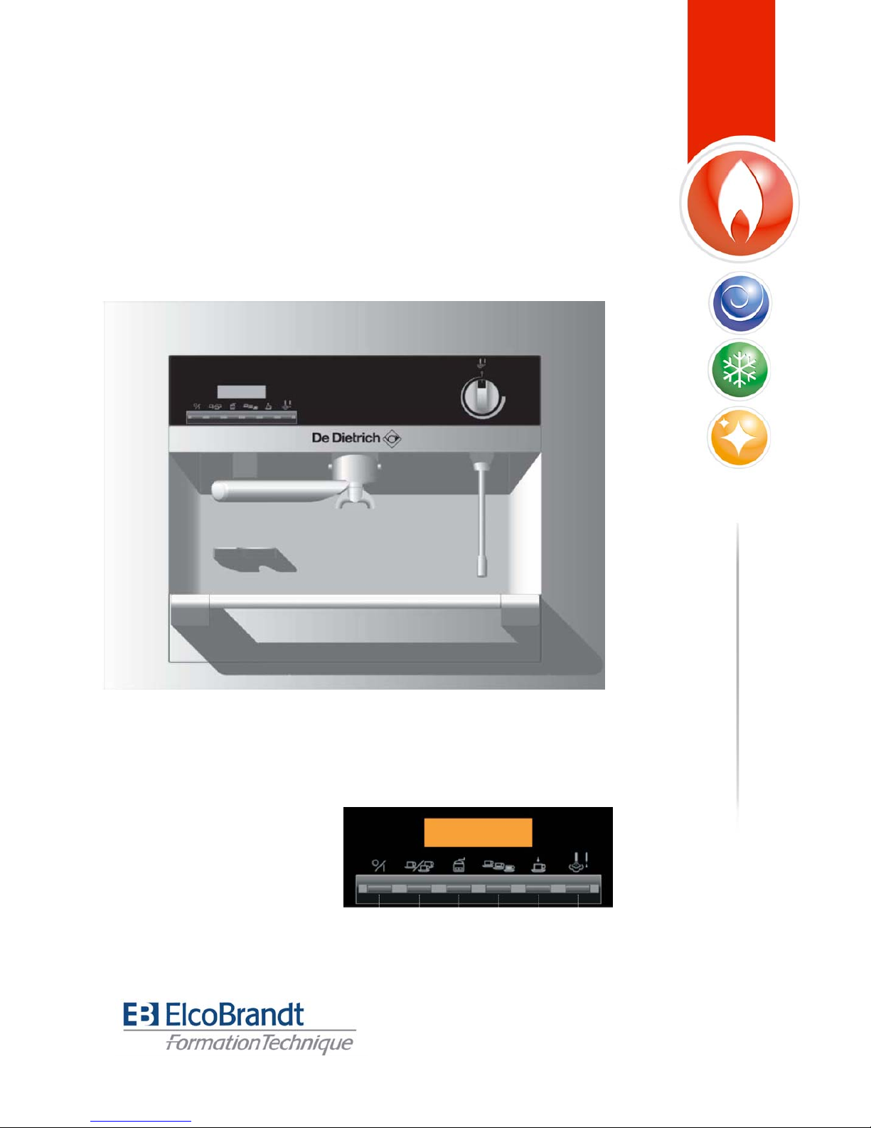
EXPRESSO
DED400XP1

SERVICING AND MAINTENANCE
SERVICE INSTRUCTION
1/04
FILTER HOLDER GROUP HEAD (O-RING)
PAGE 1-7
Problem :
Liquid drips over the side of filter holder leaking out from between filter holder and filter
holder group head during coffee infusion.
2/04
FILTER HOLDER (O-RING)
PAGE 8-14
Problem :
During coffee infusion, liquid drips out of the side of the filter holder leaking out of the area
between filter holder base and where the spouts are screwed on.
3/04
THERMOSTAT
PAGE 15-20
Problem :
Water for brewing coffee or water for hot beverages from the water (or dry steam) wand is
not delivered at the desired temperature. The cause may be that one of the two safety
thermostats on the heat exhangers defective.
4/04
STOPS - BLOCKING
PAGE 21-27
Problem :
The dual function of the drawer handle is not working properly. When the drawer is pulled
out, the whole appliance slides forward out of its housing because the blocking mechanism
is not working.
5/04
CABLE SLACK
PAGE 28-31
Problem :
The appliance (cable) that sits between the panel wall of the machine housing and the back
panel of the espresso machine on the left-hand side, should form a loup, so that the
espresso machine can be glided smoothly out of the housing. However, it is causing an
obstruction and the espresso machine does not sit flush in the built-in cabinet, the safety
switch cannot engage and thus the machine has no power supply.
6/04
COFFEE GRINDER
Problem :
PAGE 32-41
The coffee grinder is not delivering coffee even though the sound of the motor can be
heard.
7/04
SENSORS
PAGE 42-61
Problem :
Brewing and beverage water (or steam) does not reach the prescribed temperature. The
reversible thermostats on both heat exchangers for coffee and/or hot beverages are
repeatedly triggered after being manually reset, even though there appears to be no
problem with the water supply and in-let system.
8/04
CIRCUIT BOARD REPLACEMENT
PAGE 62-74
Problem :
Semi-automatic processes are not functioning, which are normally engaged by pressing the
corresponding pad on the front control panel. Problems may include :
- Grinder
- Water for coffee - not delivered
- Steam / Water - not delivered
- By pressing on/off switch - no reaction
- By pressing one or two cups of coffee - no reaction
9/04
WATER PUMP /WATER PIPE
PAGE 75-86
Problem :
The water pump is very noisy (running without water) and hot water and brewing water are
being delivered slowly because there is a problem with water flow between the water
container and the heat exchanger.
SAFETY ADVICE FOR SERVICE ENGINEERS
PAGE 87
IDRAULIC LAYOUT DIAGRAM
PAGE 88
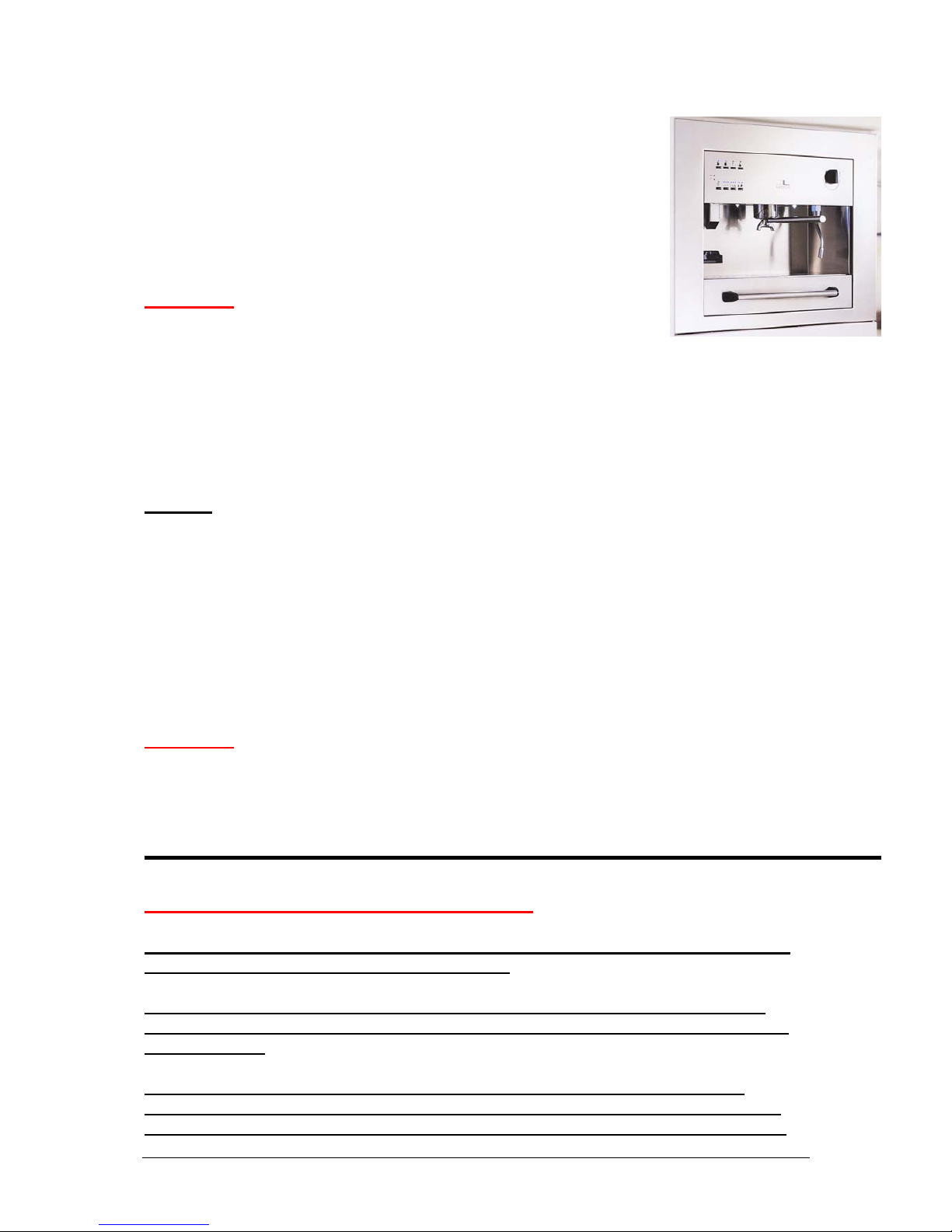
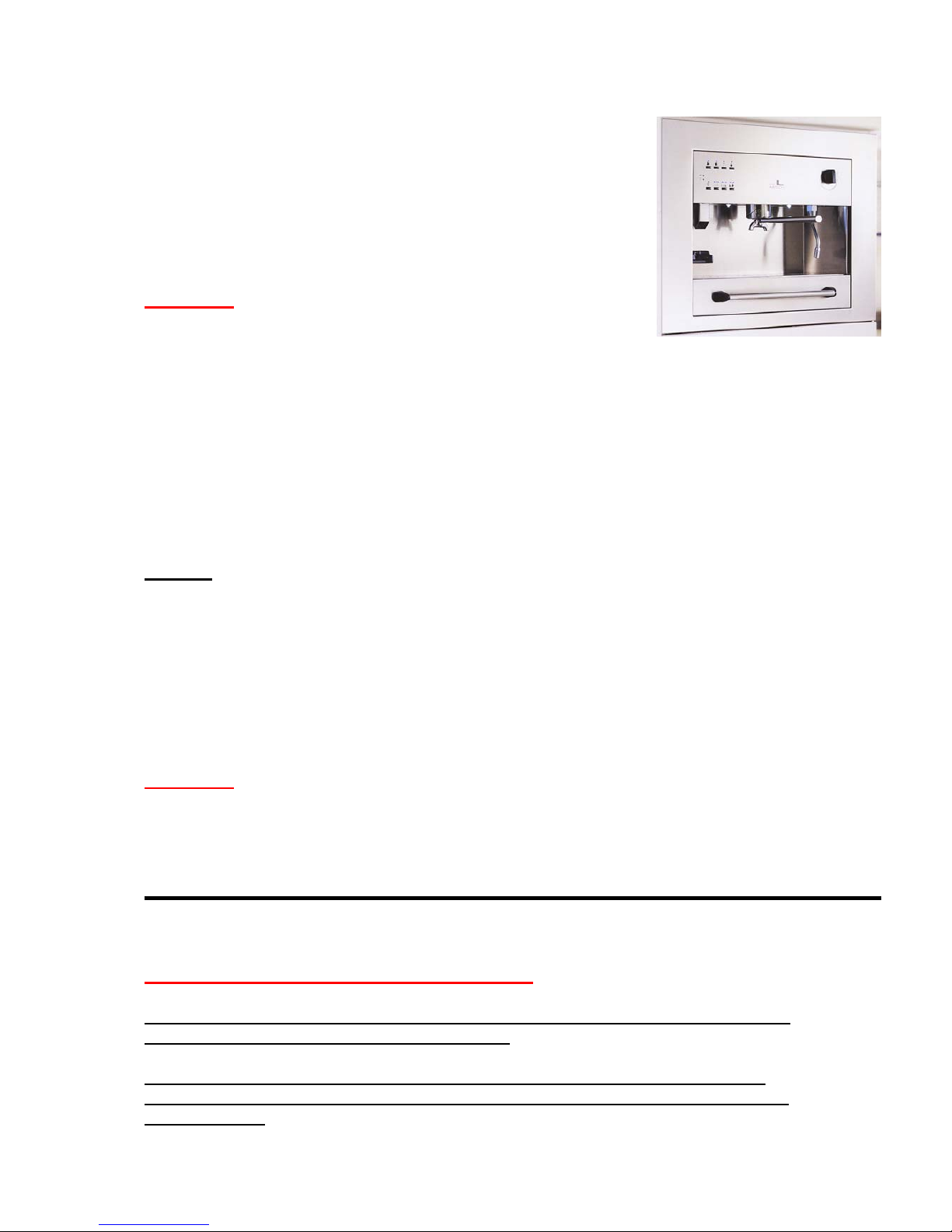
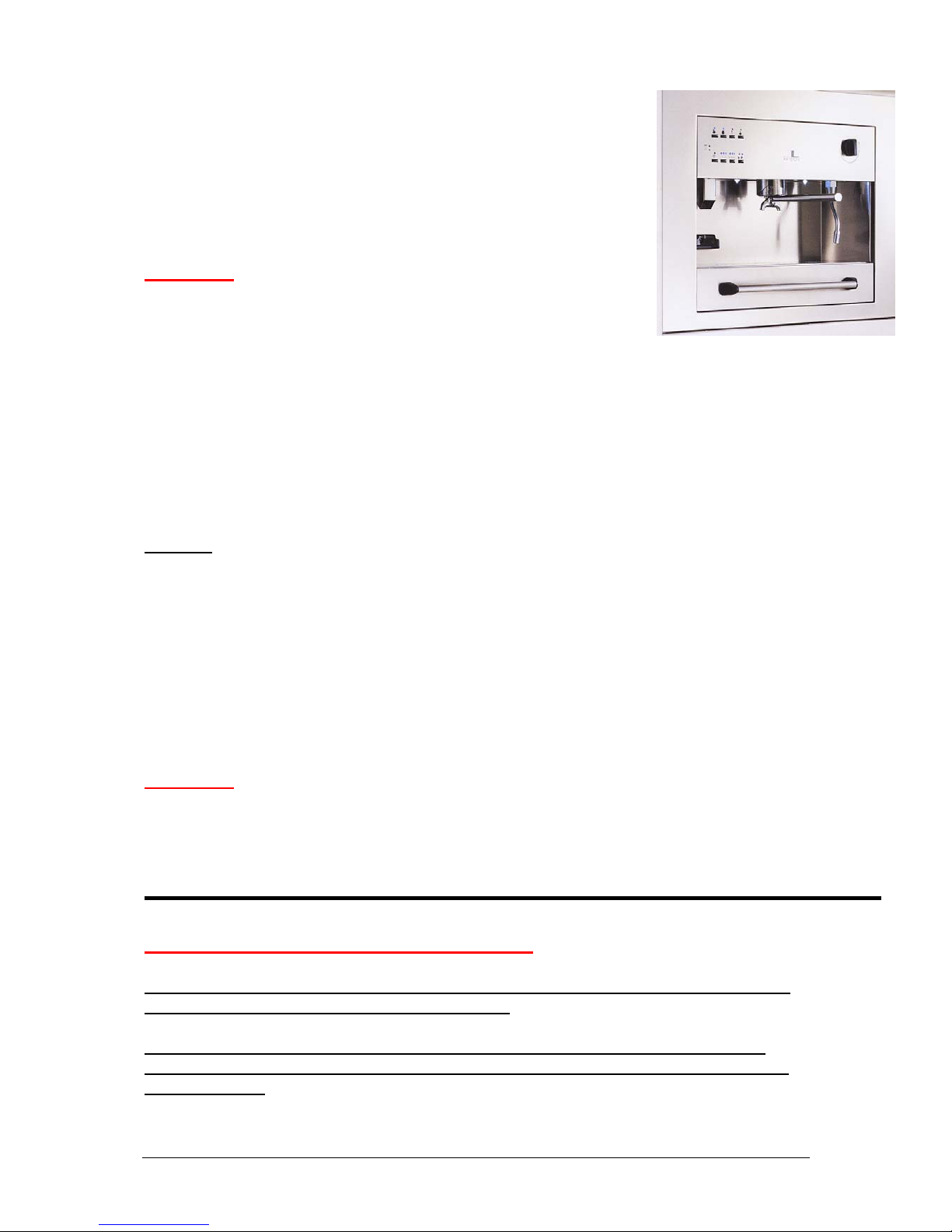
PRODUCT : SEMI-AUTOMATIC BUILT-IN COFFEE MACHINE
MODEL : SUPREME
1
Servicing and Maintenance
Product: Espresso-Machine
Model: Semi-automatic, Built-in
Service-Instruction: 1/04 Filter holder group head
(O-Ring)
Problem:
Liquid drips over the side of filter holder leaking out from between
filter holder and filter holder group head during coffee infusion.
coffee-brew should only flow out of the spouts on the lower part of the filter
holders.
Cause:
In the upper part of the group head there is the flange from which heated water
under pressure is forced through the tampered coffee during brewing. The flange
makes sure that the inner diameter of diffuser and filter holder group matches
the outer diameter of the filter holder. It is approximately 8-10 mm thick and has
a groove running around the outer edge which houses a gasket or seal made out
of heat-resistant, rubber-like material (O-ring) which normally prevents liquid
from leaking out between group head and filter holder. When the “O-Ring” is
defective or the wrong size, this can lead to the problem described above.
Solution:
The old gasket should be replaced with a new one following these
step-by-step instructions.
Safety Advice for Service Engineers
Attention: Before commencing any work on the appliance, it should be “disconnected”
from the electricity supply. This can be done by:
either removing the appliance plug from the mains socket or by isolating electricity
supply to socket through safety circuit-breaker or by turning off electricity completely
at mains switch.
As an authorised Service Engineer, you should comply with all European testing
standards and the relevant safety regulations for electrical appliances, in order not to
endanger yourself or other people and to prevent any other kind of hazards and risks.
2
For this electrical appliance, due to various systems that contribute to the working of the
machine, it is important that you observe and take note of the technical specifications of
the machine which include:
Power supply: 240 Volt mains
Heat exchanger and operating pressure up to 15 bar
Water containers and water conducting pipes (some under pressure)
Only authorised Customer Service Engineers are allowed to carry out work on this
Espresso machine (the opening of parts of the machine that are secured by screws).
European testing and safety regulations should always be complied with when carrying
out work on the appliance.
The appliance manufacturer and the Servicing firm shall not be liable for work carried
out that is not conformant with test an safety regulations and, likewise, tampering or
work carried out by unqualified servicing firms and local service engineers.
Step-by-Step procedure:
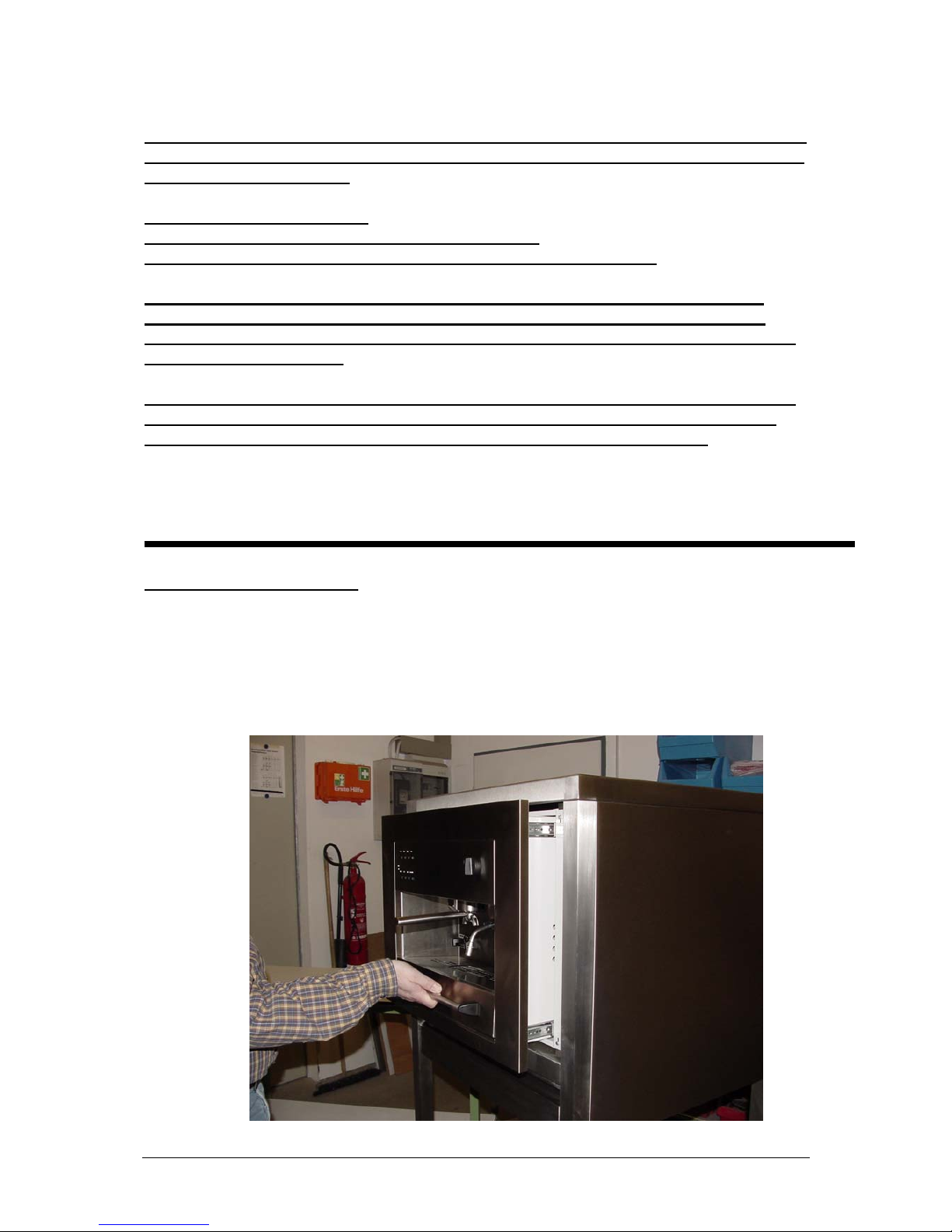
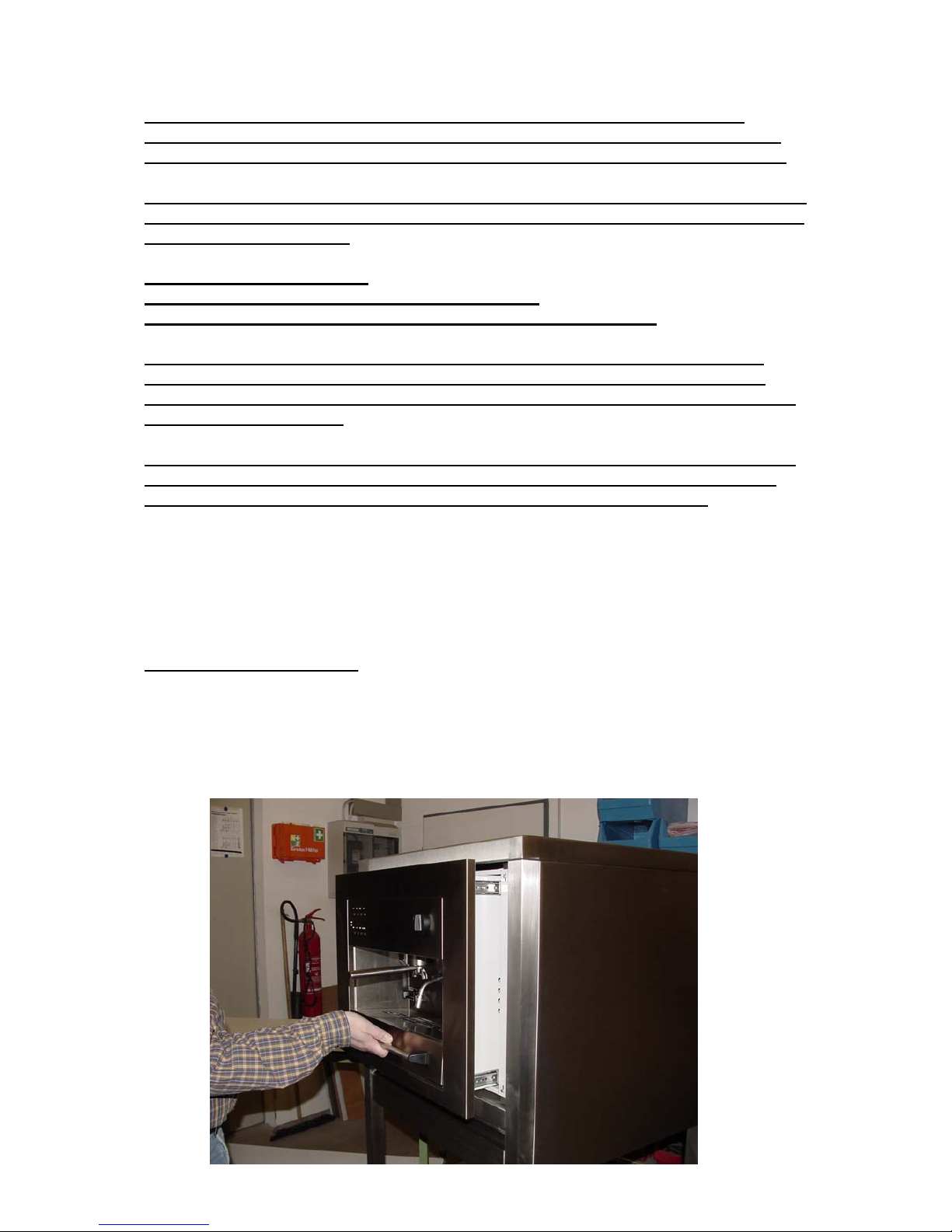
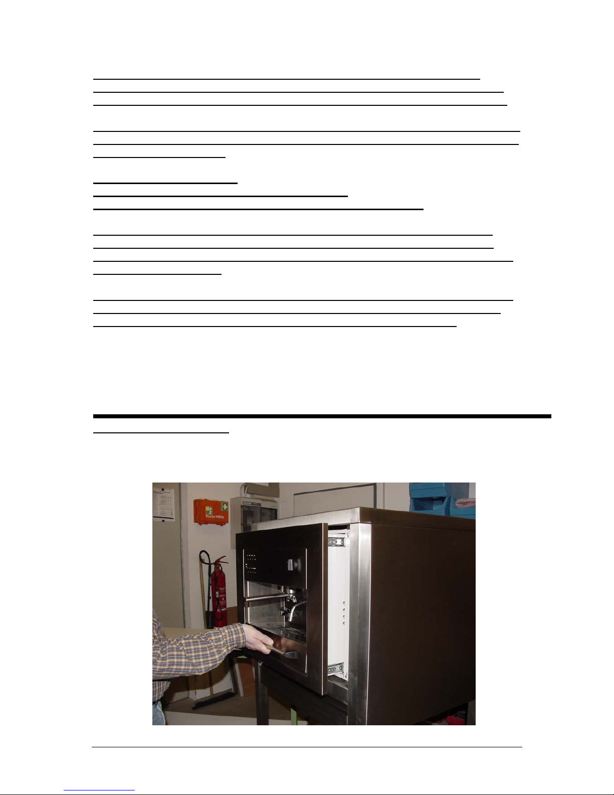
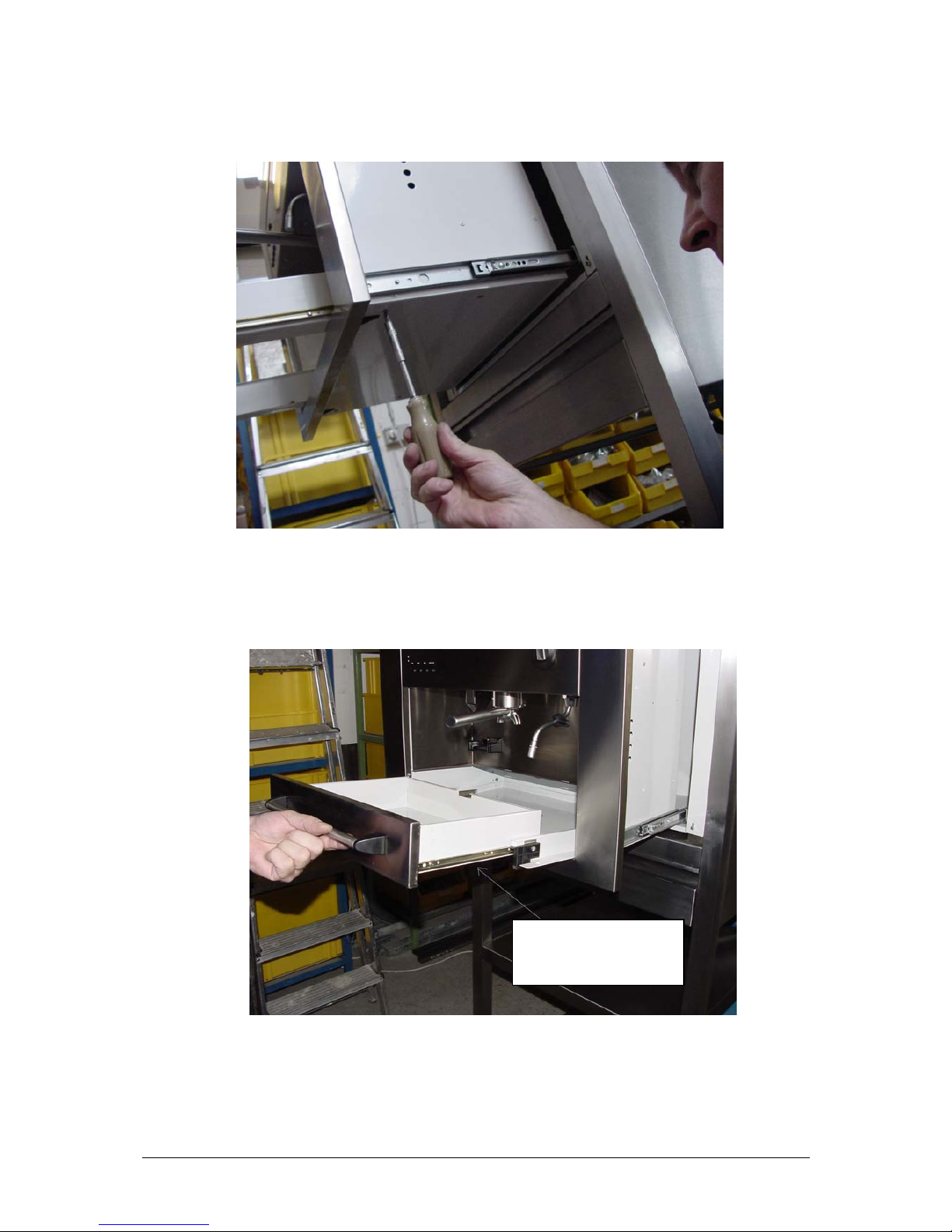
1. Firmly clutch the handle on the spill-tray drawer, and gently slide the Espresso
machine out of its housing towards you. (Opening as for water and coffee refilling
or replacing the grinder).

3
2. The upper front cover is screwed down with 6 countersunk screws. Unscrew and
remove all screws and take cover off.
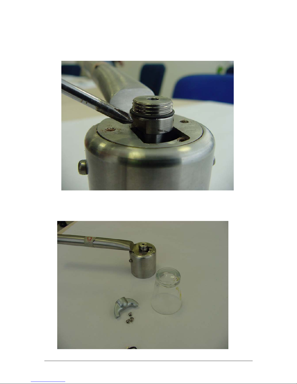
3. Using a >>M10 spanner<< and a >>M13 spanner<< proceed to loosen the nuts
on the water in-let base arrangement located on the ALU-heat exchanger.
Unscrew the six
countersunk screws
on the cover.
Then remove cover.
First, loosen the
hexagonal “M10” nut,
then remove L-bend
element holding the
flexible water in-let tube.
Next, loosen the hexagonal
“M13” corner nut. Then,
remove the top and inner metal
plates. Finally the freed water
in-let group can be removed
from below.
4
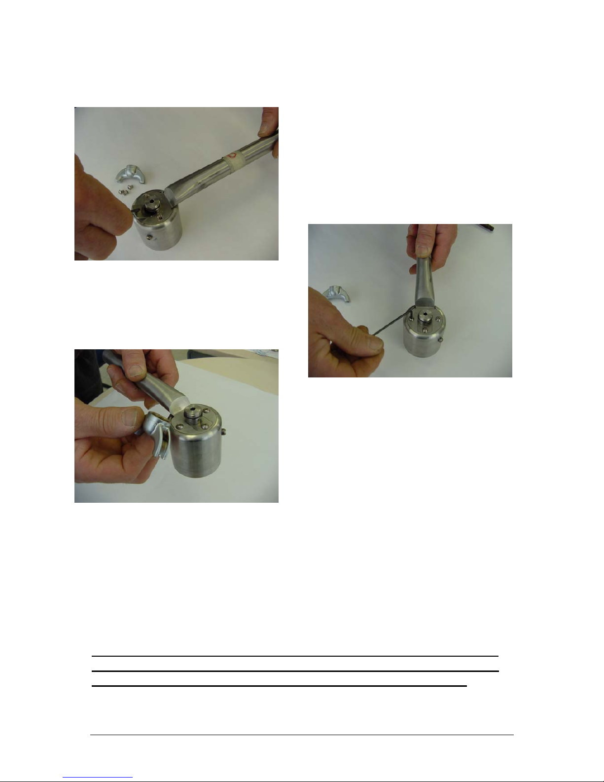
4. Firstly, using the >>M 10 spanner<< carefully loosen the nut at the base of the Lbend element by >>turning anti-clockwise<<.
Attention: There is a threaded connection attaching the L-bend element to the water
in-let group. This thread is small and delicate. On the outer thread of the L-bend
element there is a mini seal that should not be lost. It is essential that this seal is
replaced when the part is screwed back in later.
Take out element with plastic pressurised in-let tube and place it temporarily to one
side.
5. Next, using the >>M 13 spanner<< remove the water in-let assembly
Once the M13 nut has been
removed, do the same thing with
the top and lower metal plates.
Finally, the sunken group can be
pushed out below by following
the instructions in this section

5
Attention: Provided the filter holder (bayonet coupling) is locked in place, then
the upper (M13) nut can be removed from the water in-let group without any
problem.
If the filter holder is not locked in place, and when the M13 nut is finally ready to
be removed, a hand should be placed under the filter holder group head to catch
the diffuser as it is released.
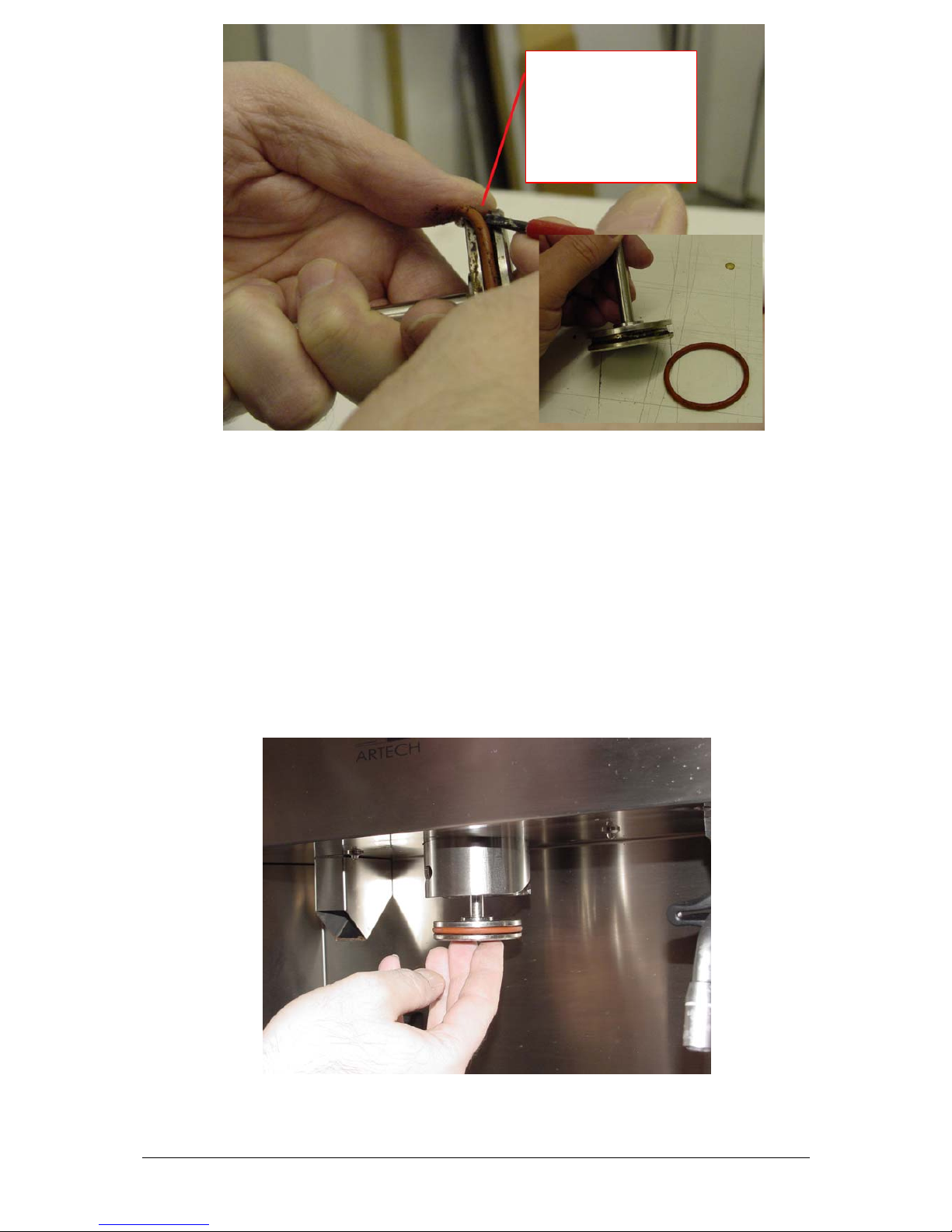
6. Removal of the diffuser
After having unscrewed and removed the water in-let assembly and the (M13)
nut and, likewise removed the top and lower metal plates on the top of the heat
exchanger, the diffuser and the insert screen can be glided out from below. You
will see that there is a groove on the outer perimeter of the diffuser that houses
the gasket (large O-Ring) that needs to be replaced.
7. Removing the gasket (O-Ring)
The description in the next section will show you how to remove the gasket.
Please avoid damaging or scratching the diffuser when removing the gasket
(use a small flat-headed screwdriver) and the delicate outer and inner thread
on the upper side.
6
Insert new gasket (large O-Ring) inside out.
After the O-Ring has been removed, a new gasket can be inserted, making sure it
goes into the groove inside out. Clean the screen, the groove (where the gasket
will sit) and the group of any residual deposits (coffee, etc.) before inserting the
new O-Ring.
After performing this operation, reassemble the entire group in reverse order:
1. Replace the diffuser by inserting it into the filter holder group head from
below and push up until it reaches the top position and the threaded part once
again protrudes out of the heat exchanger. Reposition the low and top plates
and position and tighten the (M13) nut.
Tighten the nut by turning in a clockwise direction using a >>M 13
spanner<< .
Remove the gasket from
its groove with the aid
of a small flat headed
screwdriver
7
Once the >>M 13 nut<< has been tightened, reposition the water in-let L-bend
element very carefully onto the inner thread of the water in-let arrangement on
the heat exchanger and then tighten up the M 10 nut by turning in a clockwise
direction making sure that it is >>securely<< fastened.
Remember to check that the mini seal has been replaced around the
outer thread of the L-bend element before reassembling it. Without
this seal the machine cannot be restarted up. Additional seals and
gaskets are available from the service department.
Once the water in-let tube has been reattached, the cover can be repositioned and
screwed into place using the six countersunk screws.
Finally, reposition the machine in its housing and reconnect electricity supply. Then,
switch the espresso machine back on and, after following normal start-up procedure, the
espresso machine is ready for use.
Carry out 2-3 test runs (espresso) to check whether the replacement of the gasket has
been successful.
Espresso should only be delivered from the spouts under the filter holder.
No liquid should drip out of where the filter holder group head meets the
filter holder nor should any sputtering or spraying be seen.

8
Servicing and Maintenance
Product: Espresso-Machine
Model: Semi-automatic, built-in
Service-Instruction: 2/04 Filter holder (O-Ring)
Problem:
During coffee infusion, liquid drips out of the side
of the filter holder leaking out of the area between
filter holder base and where the spouts are screwed on.
coffee-brew should only flow out of the spouts on the lower part of the filter
holders.
Cause:
Inside the filter holder there is a spring mechanism and a gasket or sealing ring
which, during coffee brewing, should prevent coffee brew from dripping over the
sides. The sealing ring in the filter holder has an almost limitless working life and
is resistant to damage due to high temperatures but a fault in the material from
which it is made may mean that it is defective.
Solution:
The old sealing ring should be replaced with a new one following
these step-by-step instructions.
Safety Advice for Service Engineers
Attention: Before commencing any work on the appliance, it should be “disconnected”
from the electricity supply. This can be done by:
either removing the appliance plug from the mains socket or by isolating electricity
supply to socket through safety circuit-breaker or by turning off electricity completely
at mains switch.
As an authorised Service Engineer, you should comply with all European testing
standards and the relevant safety regulations for electrical appliances, in order not to
endanger yourself or other people and to prevent any other kind of hazards and risks.
9
For this electrical appliance, due to various systems that contribute to the working of the
machine, it is important that you observe and take note of the technical specifications of
the machine which include:
Power supply: 240 Volt mains
Heat exchanger and operating pressure up to 15 bar
Water containers and water conducting pipes (some under pressure)
Only authorised Customer Service Engineers are allowed to carry out work on this
Espresso machine (the opening of parts of the machine that are secured by screws).
European testing and safety regulations should always be complied with when carrying
out work on the appliance.
The appliance manufacturer and the Servicing firm shall not be liable for work carried
out that is not conformant with test an safety regulations and, likewise, tampering or
work carried out by unqualified servicing firms and local service engineers.
Step-by-Step procedure:
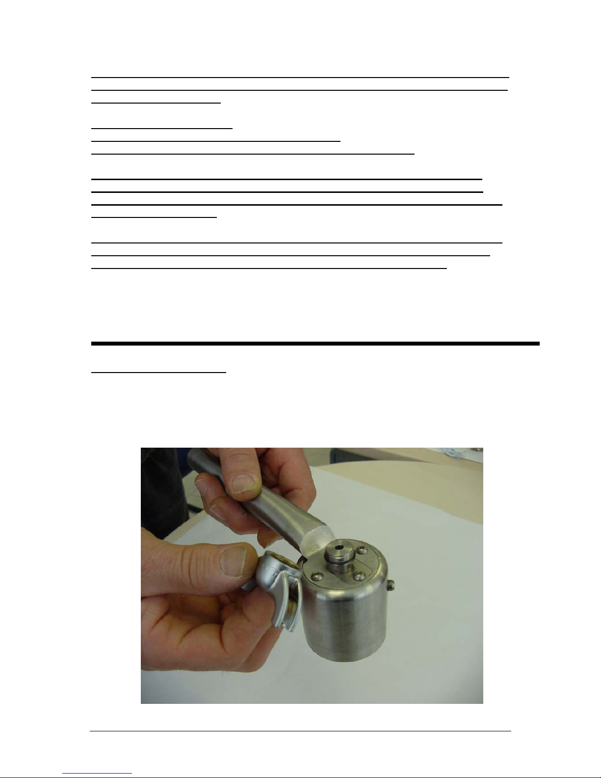
1. Unlock the filter holder from the filter holder group head with a clean sideways
movement of the handle to the left. Working on a clear work surface, turn the
filter holder upside down and unscrew the spout.
10
2. Using a small hex key (2,5 mm), unscrew the three socket head screws which fix
the two-part filter holder base to the filter holder basket.
3. Now, remove the check plate with the aid of the hex key.
11
4. Turn the threaded centre pin on the filter holder so that the spanner surfaces
(notches) are exactly parallel to the elongated straight-cut edges of the base plate
cavity of the filter holder. Please see photo below!
5. With the aid of a round object (for example a sturdy glass, as show in the photo)
that fits into the filter holder basket, place the filter holder over the glass pressing
down firmly until the filter holder spring is under tension.

12
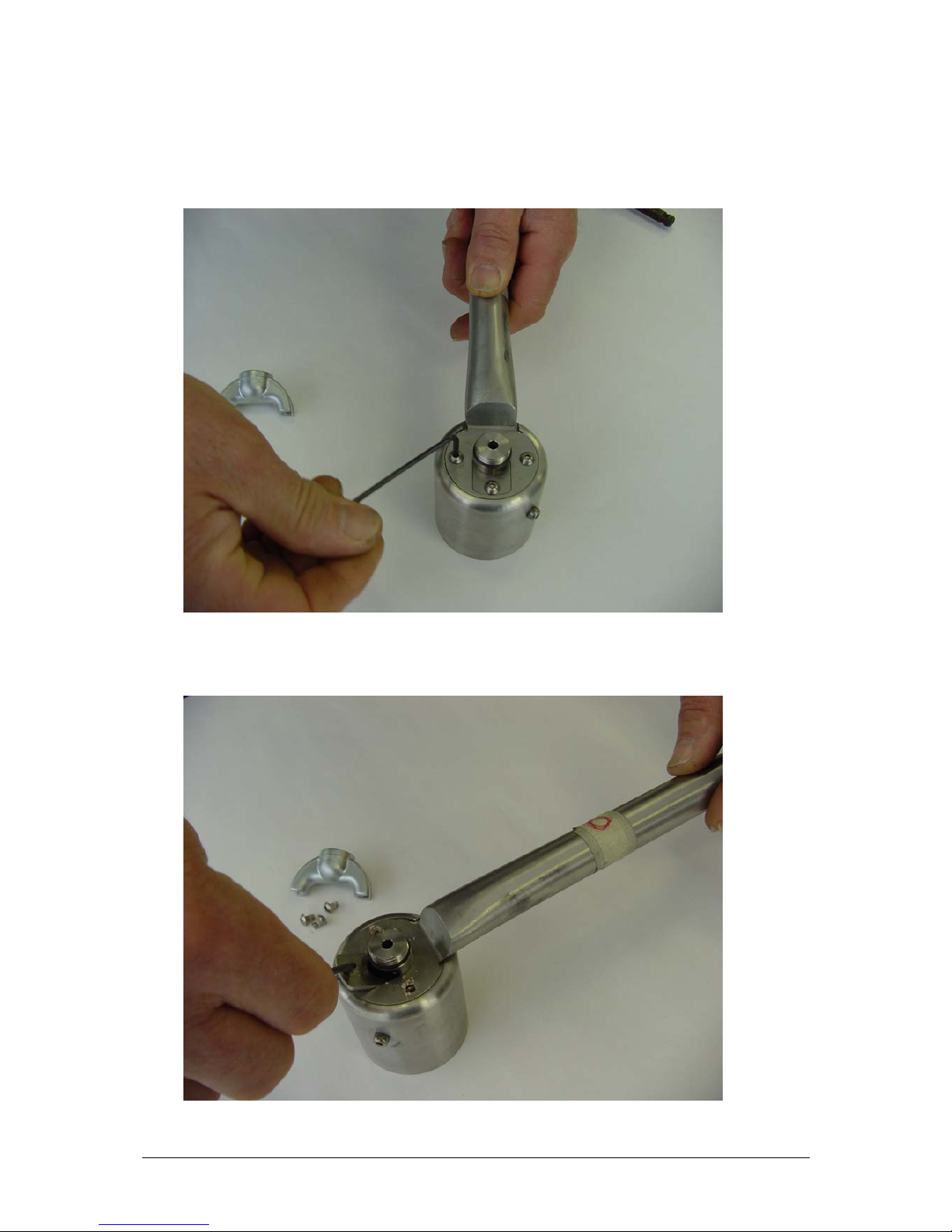
5. Using the handle, jiggle the base place out of its seating and over the threaded
centre pin.
6. The filter basket with the O-Ring (sealing ring) which is part of the centre
threaded pin assembly, and, likewise, the coiled-up spring can now be eased out
from below. The old O-ring can be replaced with a new one at this point.

13
7. Once the O-rings have been exchanged, reassemble the group following the
disassembly instructions in reverse order: The >broader< Spiral side must point
in the direction of the basket base.
Then, once again with the help of a round object (base of a glass), recoil the
spring and reassemble the base plate on the filter holder following the photo
sequence below:
1.
2.
3.
14
8. Reposition the check plate in its seating and then reposition socket screws and
tighten with the hex key. Then, screw the spout back on and tighten.
1.
2.
3.
Finally, lock the filter holder back under its group head and switch electricity back on.
Switch the machine on and, after following normal start-up procedure, the espresso
machine is once again ready for use.
Carry out 2-3 test runs (espresso) to check whether the replacement of the seal has been
successful.
Espresso should only be delivered from the spouts under the filter holder.
No liquid should drip out of the area where the threaded centre pin meets
the filter holder base nor should any sputtering or spraying be seen.
15
Servicing and Maintenance
Product: Espresso-Machine
Model: Semi-automatic, built-in
Service-Instruction: 3/04 (Thermostat)
Problem:
Water for brewing coffee or water for hot beverages from the water
(or dry steam) wand is not delivered at the desired temperature. The
cause may be that one of the two safety thermostats on the heat
exchangers defective.
Under correct working conditions, the electrical connections in the thermostats are closed and power
is delivered. In the case of a fault (for example the heat exchanger runs dry causing subsequent
overheating of the heat exchanger), the reverse circuit breaker is activated to prevent the heating
elements from burning out.
Cause:
The heat exchangers on the machine are positioned one on top of the other. Each
heat exchanger is equipped with a safety thermostat. The sensors establish the
maximum and minimum temperature of water in the heat exchanger. The safety
thermostats are activated when there is no water flowing into the heat exchanger
or when defective sensors signal abnormally high temperatures. In theses
instances, the relative thermostat is activated breaking the circuit and it
subsequently needs to be reset manually (reversible).
Solution:
The machine needs to be opened up and the upper cover removed
following the relative service instruction thus making access possible
to the two thermostats.
Safety Advice for Service Engineers
Attention: Before commencing any work on the appliance, it should be “disconnected”
from the electricity supply. This can be done by:
either removing the appliance plug from the mains socket or by isolating electricity
supply to socket through safety circuit-breaker or by turning off electricity completely
at mains switch.
16
As an authorised Service Engineer, you should comply with all European testing
standards and the relevant safety regulations for electrical appliances, in order not to
endanger yourself or other people and to prevent any other kind of hazards and risks.
For this electrical appliance, due to various systems that contribute to the working of the
machine, it is important that you observe and take note of the technical specifications of
the machine which include:
Power supply: 240 Volt mains
Heat exchanger and operating pressure up to 15 bar
Water containers and water conducting pipes (some under pressure)
Only authorised Customer Service Engineers are allowed to carry out work on this
Espresso machine (the opening of parts of the machine that are secured by screws).
European testing and safety regulations should always be complied with when carrying
out work on the appliance.
The appliance manufacturer and the Servicing firm shall not be liable for work carried
out that is not conformant with test an safety regulations and, likewise, tampering or
work carried out by unqualified servicing firms and local service engineers.
Step-by-Step procedure:
1. Firmly clutch the handle on the spill-tray drawer, and gently slide the Espresso
machine out of its housing towards you. (Opening as for water and coffee refilling
or checking the grinder).
17
2. The upper front cover is screwed down with 6 countersunk screws. Unscrew and
remove all screws and take cover off.
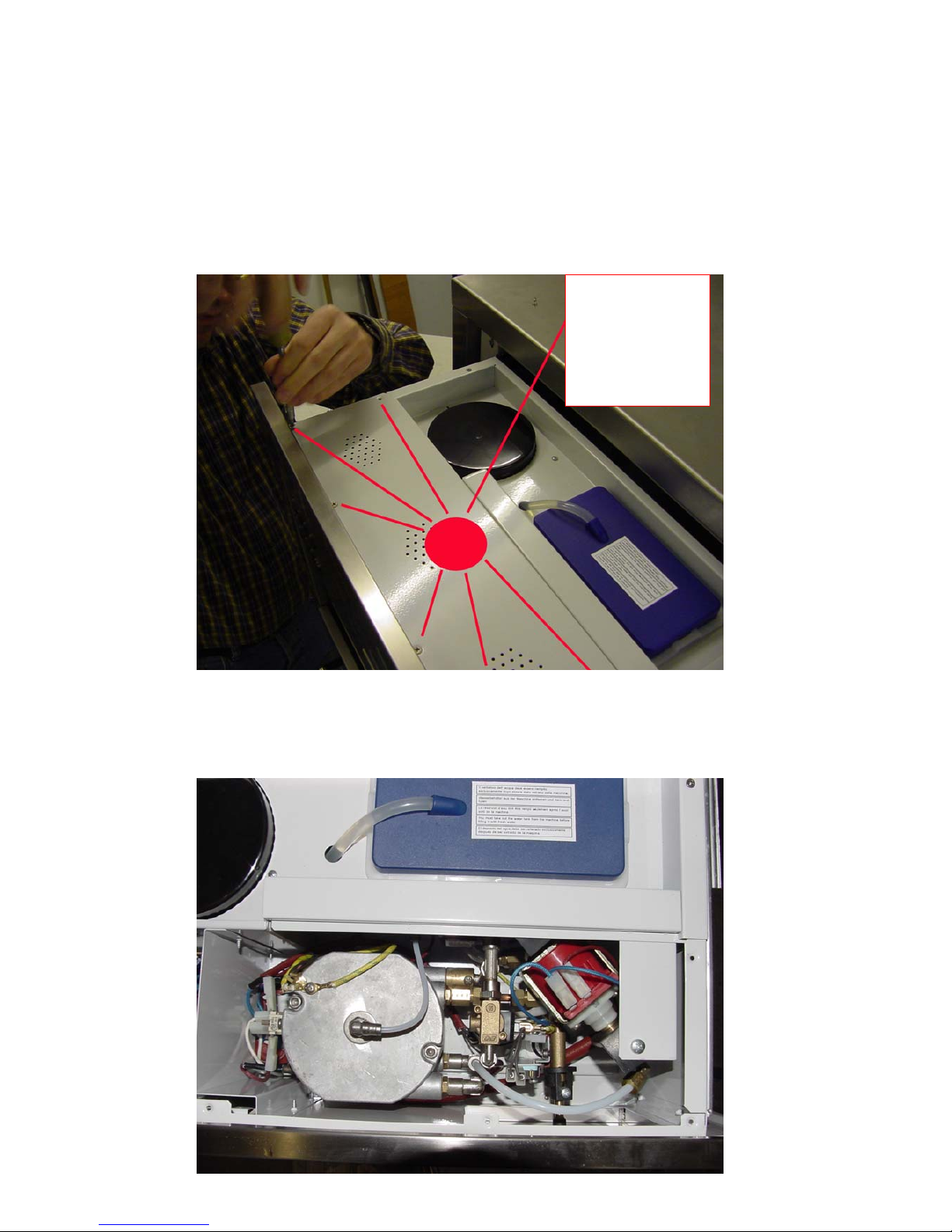
3. With the cover removed, the next photo shows the view of the inside layout from
above.
Unscrew the six
countersunk screws
on the cover.
Then remove cover.
18
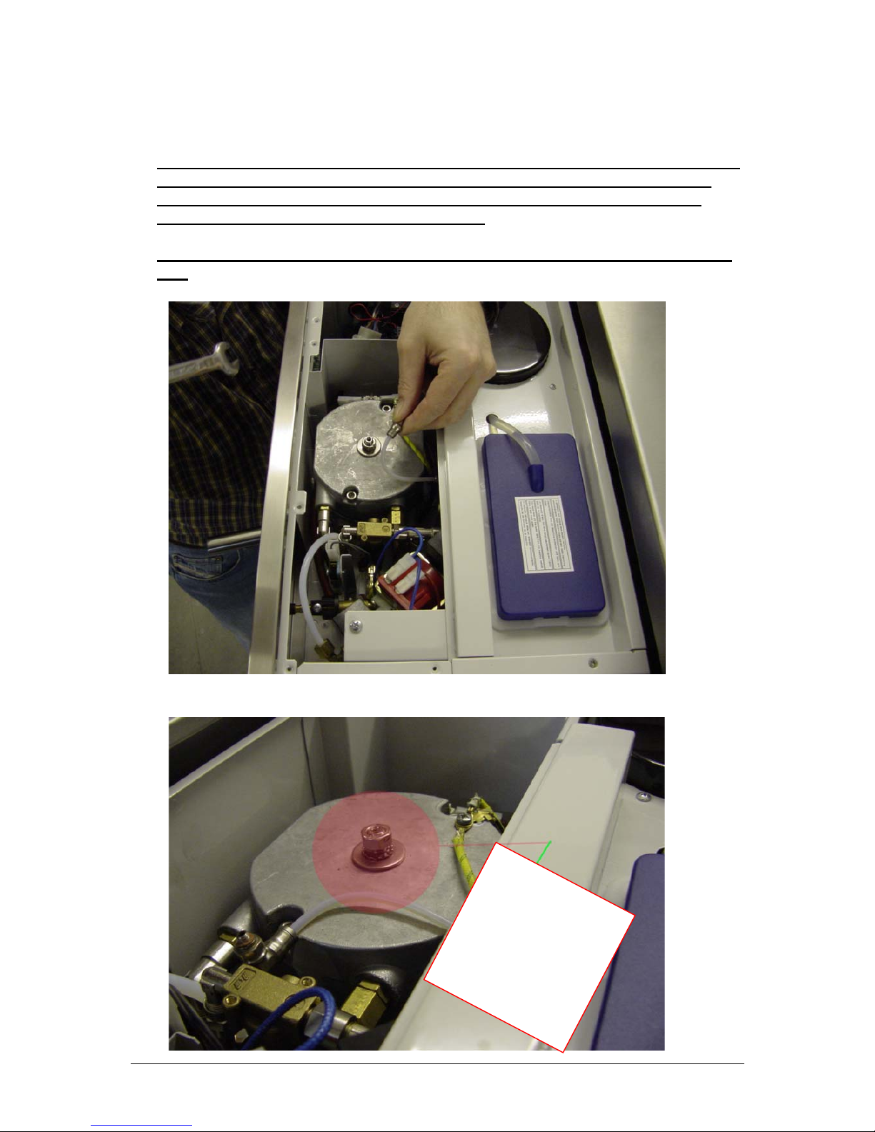
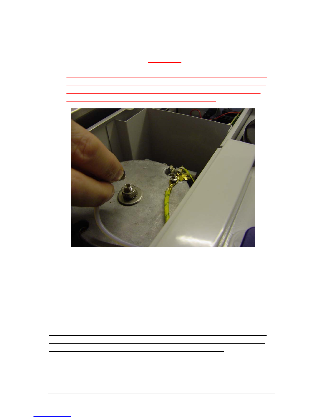
4. The following picture shows the top-positioned heat exchanger seen from above.
In the centre of the heat exchanger there is the water in-let pipe assembly
through which heated water under pressure is forced through the tampered
coffee during brewing . Top left >>at 10 O’clock<< there is the earth connection
with a brass seal under which the temperature sensor (Minimum-Maximum
operating temperatures) can be found.
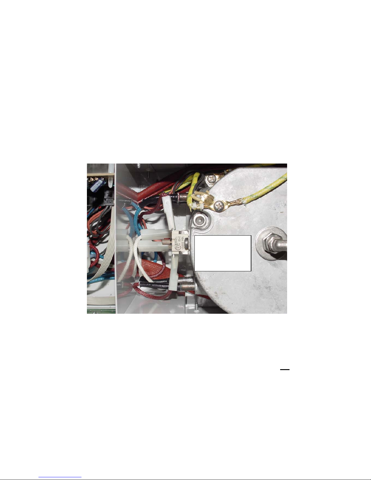
5. On the left side >>at 9 O’clock<< there is the reversible thermostat. In the
middle, between the two electrical connections, the reverse push button can be
seen (grey-brown). This push button must be in the pushed-in position.
6. After the reverse push button has been set in the pushed-in position, close the
machine for testing. (do not reassemble the top front cover!); switch the machine
on following normal start-up procedure. Wait until the top left and top right leds
(showing brewing water and hot water/steam temperature) remain alight. For
testing purposes, turn the knob on the front panel and check whether hot water is
delivered from the wand. In the event that the thermostat should cut out again,
then the fault could be with the thermostat. In this case, disconnect power supply
to machine and open it up. Follow the procedure outlined below:
a. With the aid of a very short screwdriver for phillips head screws (if available use
a rachet ), unscrew the top screw on the upper thermostat. Remove both AMP
casings and unscrew the lower Phillips screw. Remove the thermostat and apply
a small amount of heat conducting adhesive to the back of the new thermostat,
On the left, the
thermostat. Centre
the reverse push
button.
19
stick into position and screw tight using upper and lower screws. Put AMP
casings back on.
b. When the top-positioned thermostat has been unscrewed, the lower one becomes
visible and can be accessed. In the same way as before, to test the thermostat
push in the reverse (red) push button. If during the water and steam test, this
thermostat cuts out, then this could mean that it is also defective. In the case that
the bottom thermostat needs to be replaced, follow the procedure outlined for the
top thermostat. To unscrew the bottom thermostat use a suitable screwdriver.
Before doing this remove the AMP casings. The bottom thermostat makes
contact with the metal of the lower heat exchanger using a thin probe (fixed by a
screw). After the defective thermostat has been removed, apply thermal
conducting adhesive to the back of the new one, install and screw tightly into
position.
7. After having reversed (reset) the thermostat buttons and/or replaced the
thermostats, close up the machine ( do not yet screw the upper cover in place)
and test run the machine. When both brewing water and hot water/steam are
delivered from the wand at the right temperature, the repair has been carried out
successfully and the upper cover can now be screwed back into place.
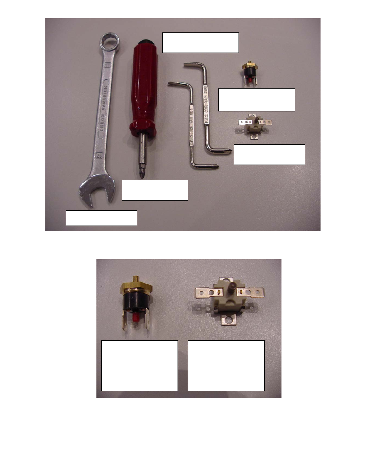
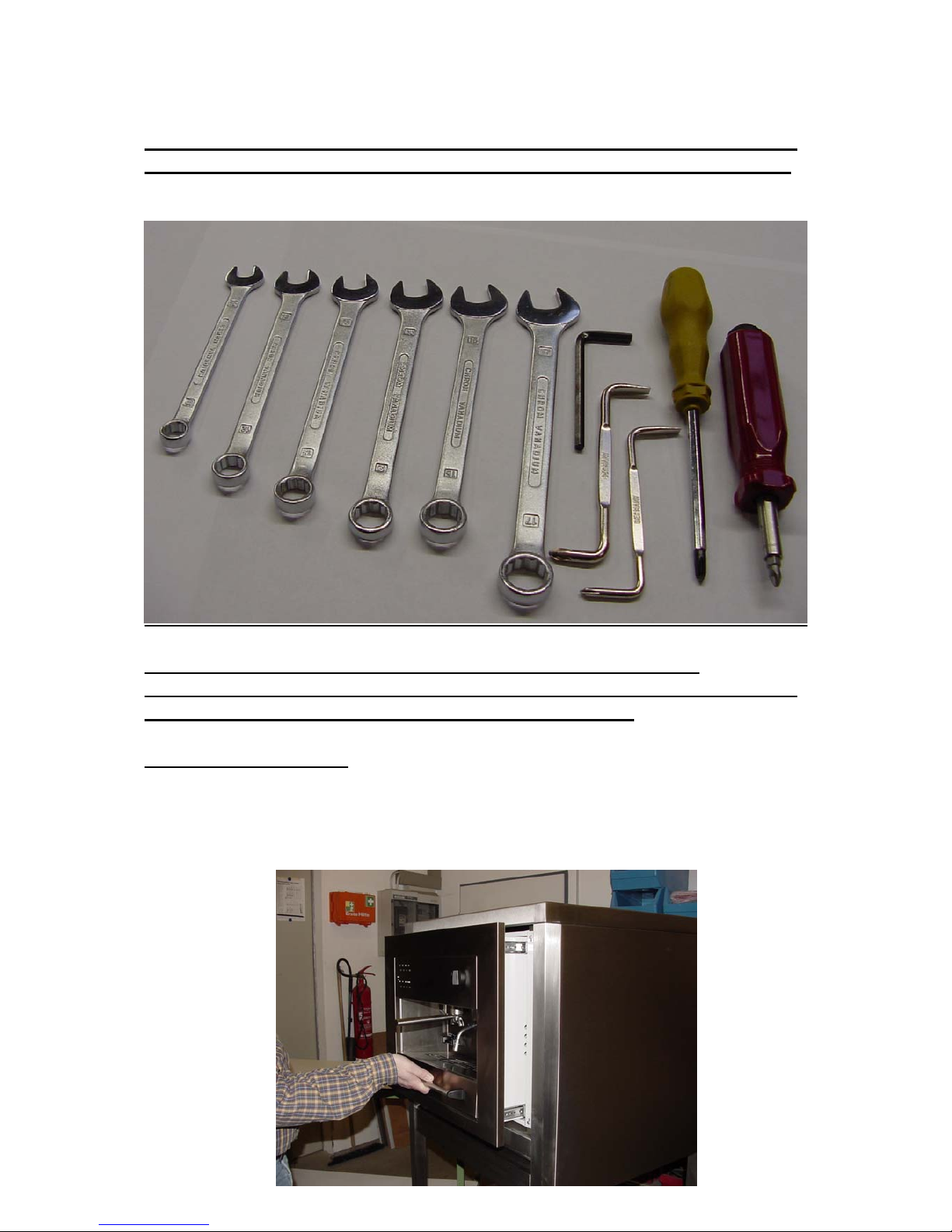
8. The following photos shows the hand tools and spare parts that are essential for
carrying out this service repair. Together with the routine delivery of thermostat
spare parts for the Espresso machine, for installing two thermostats you will also
need to order a quantity of thermal conductive adhesive. This conductive paste
must be applied to the back surface in contact with the heat exchanger of the new
thermostats to be installed.
Here above, the
thermostat for the bottom
heat exchanger
Here above, the
thermostat for the top
heat exchanger
20
No 17 spanner
Phillips head
screwdriver
Phillips head rachet
Rev-Thermostat
bottom heat exchanger
Rev-Thermostat
Top heat exchanger
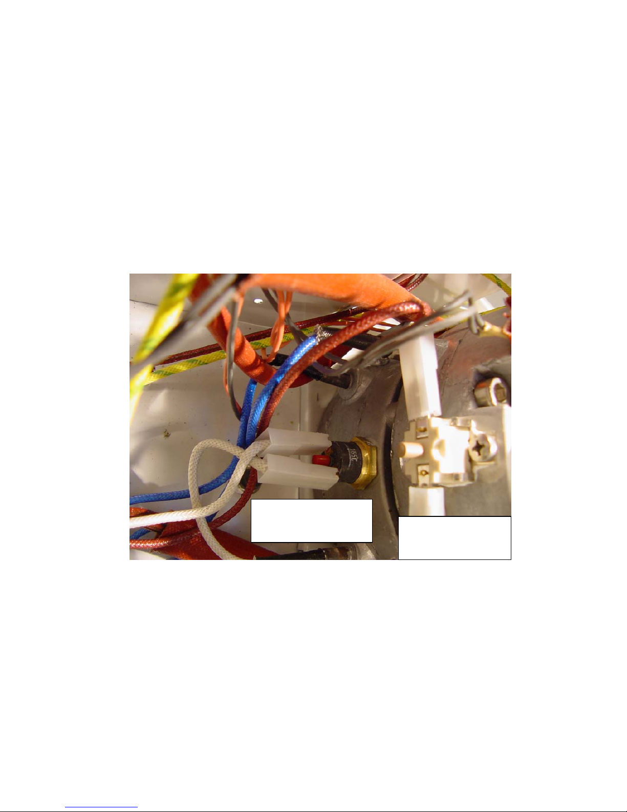
Bottom heat exchanger
thermostat
( Coffee brewing water)
165 ° C
nut size
no. 17 spanner
red reverse breaker
Top heat exchanger
thermostat
(Hot water + steam)
195 ° C
Screw holdfast plates X 2
Phillips head screws
brown reverse breaker
21
Servicing and Maintenance
Product: Espresso-Machine
Model: Semi-automatic, built-in
Service Instruction: 4/04 Stops - blocking
Problem:
The dual function of the drawer handle is not
working properly. When the drawer is pulled out,
the whole appliance slides forward out of its housing because the
blocking mechanism is not working.
Only when the drawer handle is lifted and pulled should the appliance come out
of its housing. By simply pulling the drawer handle, only the drawer should come
out.
Cause:
The movement required to slide the appliance out of its housing is for the handle
to be grasped and lifted slightly upwards; when this mechanism is working
correctly the stops blocking the appliance on the right and left sides of the
machine are released, so that the appliance slides along the glides and can be
pulled forward. Sometimes a production defect means that these stops are not
locked into position behind the corresponding groove (they do not fall into
position) so that the appliance is pulled forward out of its housing every time the
drawer is opened.
Solution:
The plastic stops need to be filed down so that they engage with the
grooves on the glide frames on the housing of the appliance.
Safety Advice for Service Engineers
Attention: Before commencing any work on the appliance, it should be “disconnected”
from the electricity supply. This can be done by:
either removing the appliance plug from the mains socket or by isolating electricity
supply to socket through safety circuit-breaker or by turning off electricity completely
at mains switch.
22
As an authorised Service Engineer, you should comply with all European testing
standards and the relevant safety regulations for electrical appliances, in order not to
endanger yourself or other people and to prevent any other kind of hazards and risks.
For this electrical appliance, due to various systems that contribute to the working of the
machine, it is important that you observe and take note of the technical specifications of
the machine which include:
Power supply: 240 Volt mains
Heat exchanger and operating pressure up to 15 bar
Water containers and water conducting pipes (some under pressure)
Only authorised Customer Service Engineers are allowed to carry out work on this
Espresso machine (the opening of parts of the machine that are secured by screws).
European testing and safety regulations should always be complied with when carrying
out work on the appliance.
The appliance manufacturer and the Servicing firm shall not be liable for work carried
out that is not conformant with test an safety regulations and, likewise, tampering or
work carried out by unqualified servicing firms and local service engineers.
Step-by-step procedure:
1. Clasp the drawer handle and lift so that the Espresso coffee machine glides
forward (opening as for water and coffee filing or checking the grinder).
23
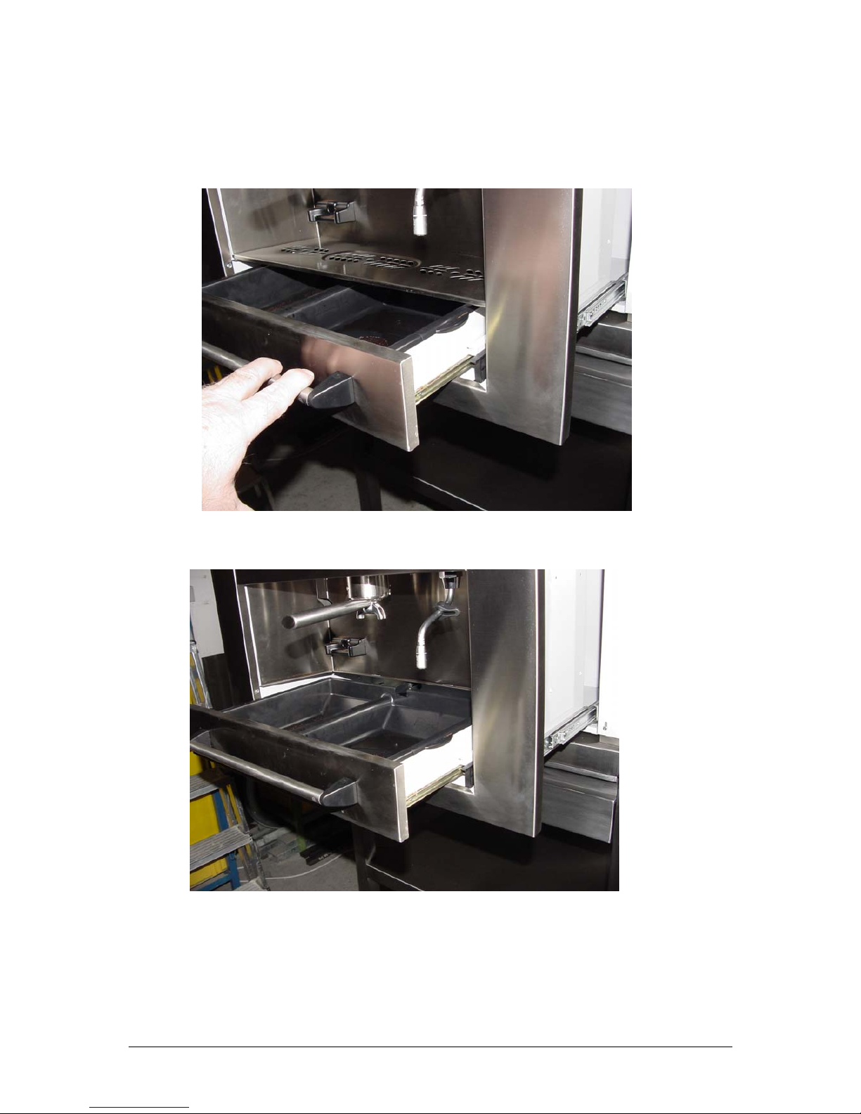
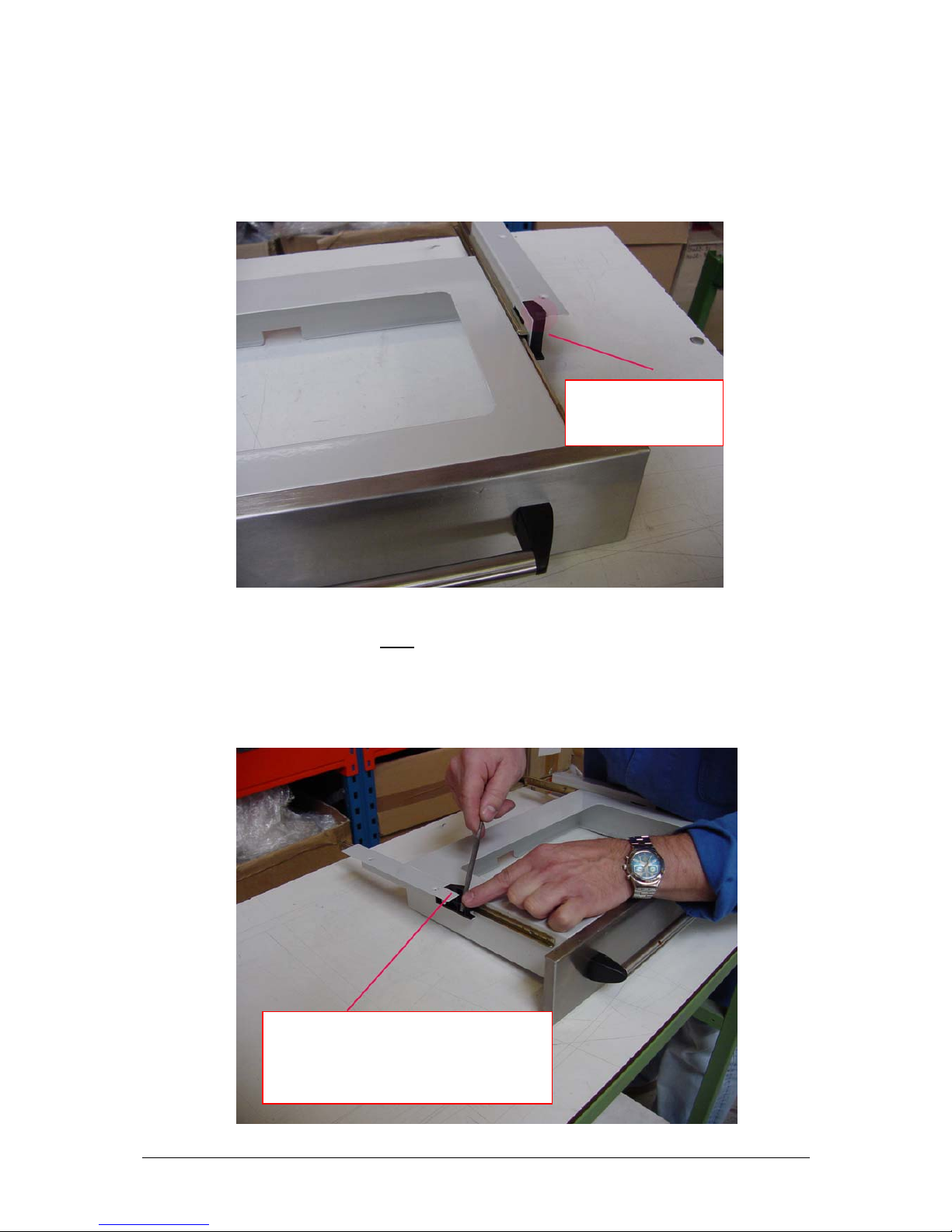
2. After the machine has been pulled out, now pull at the drawer out until it reaches
its most forward position. Remove the top spill plate.
3. Remove the double-partition drawer liner.
The next photo shows one of the two (black) stops that need to be worked on.
24
Disassemble the whole drawer to make it easier to access the two stops from which
you will need to file off a small layer of plastic.
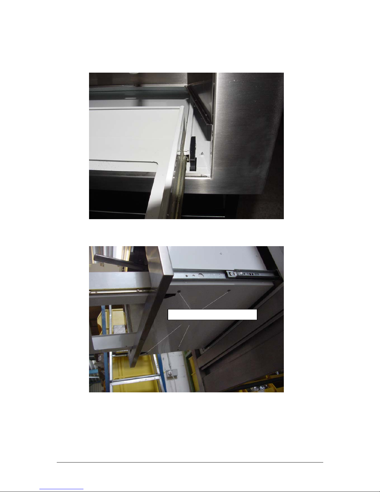
4. The whole drawer assembly is fixed underneath with four counter-sunk screws.
These screws can be accessed easily from below and need to be unscrewed.
Unscrew these four screws
25
5. Unscrew all 4 screws from below. This frees the whole drawer assembly which
can now be taken out.
6. You will find easier to work if you place the whole drawer assembly upside down
on a table. Now the corners of glide notches can be worked on comfortably.
After having taken out the 4 screws,
remove the whole drawer assembly
including the glide system and
place it upside down on a table
.
26
7. Now you need to file away about 2mm of material from the sloping surface of
the small, approximately 5 x 5 mm plastic components. It is better to >>file off a
bit more rather than a bit less<< , otherwise when you have re-assembled the
drawer, you will not have obtained the desired result, and this will mean having
to repeat the whole procedure one more time.
8. The small surfaces on both plastic components need to be filed down. These
surfaces should maintain the existing sloping edge, so that later, when they have
been re-assembled that can >>glide<< more easily behind the housing frame.
After final re-assembly, the drawer, after the appliance has been reinstalled in its
housing, should descend slightly (4-5 mm) and engage.
You will need to file off
about 2 mm of plastic from
the upper corner of this stop
using a small file.
File off about 2 mm from the top corner of the small
(approx. 5 x 5 mm) sloping surface only. In normal use the
draw should engage on this sloped surface. The appliance
should not glide out of its housing when the handle is lifted,
otherwise when the stops are lowered and engaged on the
drawer should slide out.

27
Only after lifting the drawer handle should the appliance glide out of its housing.
When the drawer handle is simply pulled, only the drawer should pull out.
Reassemble in reverse order:
1.
2.
3.
FINISHED!

28
Servicing and Maintenance
Product: Espresso-Machine
Model: Semi-automatic, Built-in
Service Instruction: 5/04 Cable slack
Problem:
The appliance (cable) that sits between the panel wall of the machine
housing and the back panel of the espresso machine on the left-hand
side, should form a loop, so that the espresso machine can be glided
smoothly out of the housing. However, it is causing an obstruction
and the espresso machine does not sit flush in the built-in cabinet, the
safety switch cannot engage and thus the machine has no power
supply.
Under correct working conditions, when the machine has been pulled out, the
power cord should lay in a straight line between the strain relief device at the
back, on top, on the outer housing and the cord feed-in point in between the two
panels. There should be no cord slack between the appliance and the outer
housing panel wall.
Cause:
The cord is not sitting in the prescribed way, that is, entering from behind and
running along the top in the fixed strain relief clamp on the outer housing and in
a straight line to the entry point on the appliance that is positioned in about the
centre of the machine in between the two wall panels, but it is forming a loop of
slack. When the machine is pushed into its housing cabinet, the length of the cord
(of varying size) forms a loop of slack in between the two wall panels. A red
plastic runner can be found at the back that supports the cord ensuring that the
movement of the cord is smooth between the two wall panels.
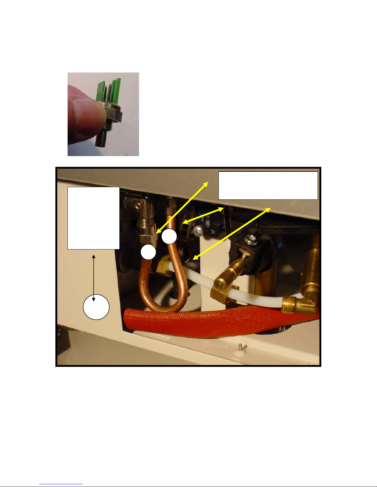
Solution:
Taking the cord >>between two fingers<< push it a far to the right as
possible between the two wall panels and check that cable moves
smoothly on the >>free side<< (between appliance and cabinet back
wall panel). If this is not the case, >>bend<< the cord into the correct
shape. The loop in the cord should only be formed inside the two wall
panels. No loop or slack should be formed on the >>free<< side,
otherwise it will form an obstruction between the appliance back
panel and the fixed (screwed to the cabinet) housing back panel.

29
Safety Advice for Service Engineers
Attention: Before commencing any work on the appliance, it should be “disconnected”
from the electricity supply. This can be done by:
either removing the appliance plug from the mains socket or by isolating electricity
supply to socket through safety circuit-breaker or by turning off electricity completely
at mains switch.
As an authorised Service Engineer, you should comply with all European testing
standards and the relevant safety regulations for electrical appliances, in order not to
endanger yourself or other people and to prevent any other kind of hazards and risks.
For this electrical appliance, due to various systems that contribute to the working of the
machine, it is important that you observe and take note of the technical specifications of
the machine which include:
Power supply: 240 Volt mains
Heat exchanger and operating pressure up to 15 bar
Water containers and water conducting pipes (some under pressure)
Only authorised Customer Service Engineers are allowed to carry out work on this
Espresso machine (the opening of parts of the machine that are secured by screws).
European testing and safety regulations should always be complied with when carrying
out work on the appliance.
The appliance manufacturer and the Servicing firm shall not be liable for work carried
out that is not conformant with test an safety regulations and, likewise, tampering or
work carried out by unqualified servicing firms and local service engineers.
Step-by-step procedure:
1. Photos 1 and 2 show the machine that has been pulled completely out to the front
and the running of the cable from the side round to the back (to the strain relief
clamp). When the cable is positioned correctly it should form a loop between he
two panel walls. The small red plastic runner should be fixed firmly to the narrow
corner edge at the back preventing the cord from chaffing with the metal.

30
Photo 1 Photo 2
2. Photo 3 shows the cable after the side panel has been unscrewed, and how it
should run correctly behind the side panel. The cable should be placed as far to
the right as possible behind the panel. This can be done by taking the cable
between two fingers
and pushing it from left to right into the gap inside the
panel. The cable should not form a loop of
slack at the back of the housing but should
run fairly taught from the upper strain relief
device to the red plastic support clip.
The cable slack should only run in the gap behind
the two panels, as shown.
The next two photos show the red plastic support
clip (cable protection) and how the cable should run
from in between the two panels and behind and up
to the strain relief device.
Photo 3
At this point, the cable should run
diagonally upwards. When the machine
is repositioned inside its housing the
cable should not form any slack. Slack
cord between the back panel of the
machine (that needs to be moved in and
out of out of its housing) and the back
panel of the housing (screwed to the
cabinet) will create an obstruction and
prevent proper closing and engagement.
As a result, the limit switch cannot
engage, the machine does not work and
the espresso machine comes out of its
housing every time the drawer is
opened.
Photo 4

31
Photo 5
Check that the red plastic
protective clip is always fixed to
the narrow curved edge of the
back outer panel!!!

32
Servicing and Maintenance
Product: Espresso-Machine
Model: Semi-automatic, Built-in
Service-Instruction: 6/04 Coffee Grinder
Problem:
The coffee grinder is not delivering coffee even
though the sound of the motor can be heard.
In correct working conditions, the coffee grinder should deliver ground coffee
from the hopper. The degree of the desired coffee grind can be set individually
when the machine is moved out of its housing (dual function of the front drawer
handle - to pull out machine lift handle and pull). On the left-hand side of the
machine there is the grind selector for choosing the desired grind of coffee.
Cause:
a. This could that the grinder has been set wrongly. The grind is set too
fine, so that the milling wheels of the grinder are so close together that
coffee beans cannot pass between them.
b. Because the grind selection has been set to >>very fine<< the milling
wheels have already come into direct contact with each other and this
has caused damage to the plastic milling wheels that are housed in the
gear motor part of the appliance. The gears have been permanently
damaged.
Solution:
To a.
Pull the machine out of its housing. Remove coffee bean hopper cover
and empty. At the back of the machine, on the left-hand side, feel for
the safety switch and manually press and hold. At the front of the
machine control panel, activate grinder (you should hear the sound of
the motor) and look into the hopper to see whether the milling wheel
is turning. If the milling wheel is turning, then the grinder has not
been damaged. In this case follow this procedure:
Using the grind selector, turn the dial at least ten times in the
direction of >>coarse<<. Fill hopper with coffee beans and start
grinder. If the coffee hopper delivers ground coffee, then the problem
is a question of grind selection and can be solved by carefully
selecting the desired grind by turning the dial back and forth.
Remember to read the operating instructions (and not select a very
fine grind!!)

33
To b.
When the milling wheels in the grinder are not turning, but the sound
of the motor can be heard, this means that the grinder is damaged
and a new grinder must be installed following this service and repair
instruction procedure.
Safety Advice for Service Engineers
Attention: Before commencing any work on the appliance, it should be “disconnected”
from the electricity supply. This can be done by:
either removing the appliance plug from the mains socket or by isolating electricity
supply to socket through safety circuit-breaker or by turning off electricity completely
at mains switch.
As an authorised Service Engineer, you should comply with all European testing
standards and the relevant safety regulations for electrical appliances, in order not to
endanger yourself or other people and to prevent any other kind of hazards and risks.
For this electrical appliance, due to various systems that contribute to the working of the
machine, it is important that you observe and take note of the technical specifications of
the machine which include:
Power supply: 240 Volt mains
Heat exchanger and operating pressure up to 15 bar
Water containers and water conducting pipes (some under pressure)
Only authorised Customer Service Engineers are allowed to carry out work on this
Espresso machine (the opening of parts of the machine that are secured by screws).
European testing and safety regulations should always be complied with when carrying
out work on the appliance.
The appliance manufacturer and the Servicing firm shall not be liable for work carried
out that is not conformant with test an safety regulations and, likewise, tampering or
work carried out by unqualified servicing firms and local service engineers.

34
Step-by-step procedure:
1. When the machine has been pulled out, both upper covers need to be unscrewed and
removed.
2. First remove the cover at the front. Look at the following photos as a guide:
Photo 2/1
Photo 2/2
Unscrew the six
countersunk screws
on the cover.
Then remove cover.

35
3. Next remove the back cover. First, remove the cover on the water container and coffee
container. Remove the round plastic filter holder on the end of the water tube and slide
the tube out of the opening in the cover, remembering first to use a felt-tipped pen to
mark the position of the tube in the water container so that it can be replaced in the same
position. This is important as you will see later. Place both covers to one side. Observe
the following photos:
Photo 3/1 Photo 3/2
Photo 3/3 Photo 3/4
4. The water container mounting now needs to be disassembled. To do this, the
stops on the thin side walls for the front dividing panel must be pushed as far
back as possible so that the mounting can be pushed up to the top and removed.
The base of the mounting is sprung. So please be careful that this spring is not
lost. When re-assembling the mounting, position the base horizontally and
reinsert the side plates in the corresponding >>slots << . (See the following
photos)

36
Photo 4/1
Photo 4/2 Photo 4/3
5. In photo 4, looking in a diagonal direction from above, you can see the grinder motor
below. You can also see the wiring. The two AMP – plug connections for the power
supply can be disconnected. You should trace the earth wiring through the housing
opening and into the front section of the machine. The plug is positioned on the front
water valve and must be disconnected.
The safety tabs
must be bent so
that the container
can be pushed up.

37
6. After having loosened the earth wire on the front water valve (see photo), you can now
get to work on disassembling the grinder.
7. You are looking down into the empty coffee bean hopper. You will see two socket
screws that should be unscrewed and removed. Detach the transparent hopper
from the grinder and remove. Remember that the mark on the rim of the
transparent hopper should positioned later on the left-hand side.
8. Now, it is the turn for the grinder to be disassembled. First unscrew the four
socket head screws (see photo on the next page) The front screw on the left is not
easy to access and is partially hidden by the axel arrangement of the grind
selector. Once all four screws have been removed, the small transmission worm
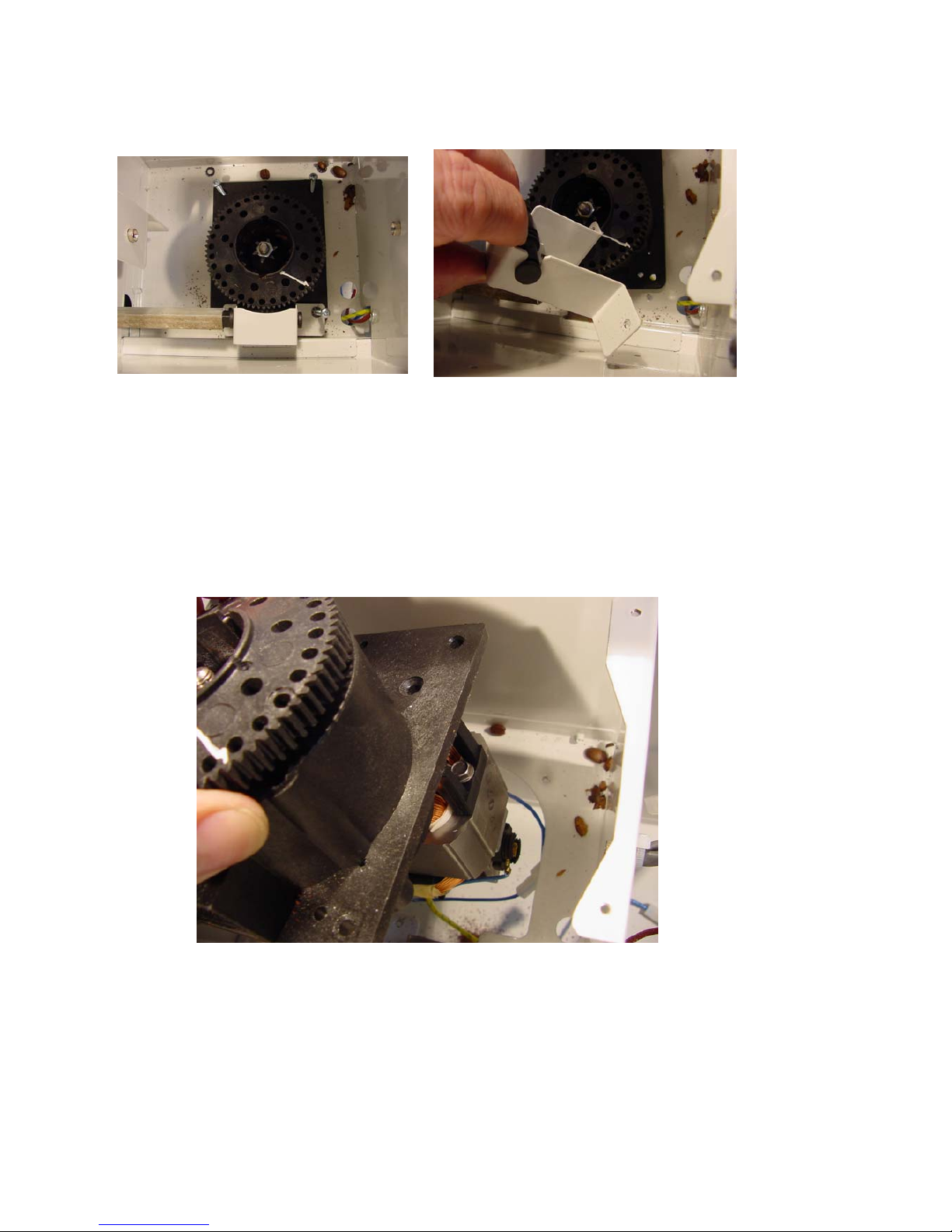
38
screw (behind the white cover) can be removed and by jiggling the whole grinder
slightly the square axel can be uncoupled ; remove the worm screw!
Photo 8/1 Photo 8/2
9. Now the entire grinder assembly consisting of motor and gearbox containing the
milling wheels can carefully be taken out. During this operation, manually pull
the two electrical wires and the long earth wire through the housing shaft
opening.
Photo 9/1

39
10. You should now prepare the new gear motor assembly so that all plug connections
have unmistakable >>male<< and >>female << terminals and so that the
electrical connections that will be set up will work correctly. Now, working in
reverse order, firstly replace the gear motor into its corresponding shaft and
roughly position. Then connect up the blue and brown wires using suitable plugs
and insert the earth wire through the corresponding gap in the housing so that it
comes out into the front section of he machine and, there, reconnect it to the
water valve.
Photo 10/1
11. Now the worm screw forming part of the angled transmission on the grind
selector should be positioned so that it engage with the teeth of the gear motor
wheels. At the same time, the coffee outlet on the grinder must be positioned so
that it is matches that of the coffee hopper at the front and connection in the
square hole set up.
12. Now reposition plates that were previously removed carefully over the holes and
insert socket screws and tighten.
13. Next, reposition the transparent water holde , remembering to >>carry out<<
suitable tap connection and fix the container using the two black screws.

40
14. When re-assembling the mounting for the water container, remember that the
sprung base plate should be engaged in the appropriate holes in the side panels.
After the mounting assembly has been reinserted, bend the safety latches slightly
outwards so that the mounting for the water container is secured.
15. Now, replace the back upper cover. The tube that delivers water from the flow
gauge to the container must be put back into position very carefully.
It should be re-inserted into the round opening on the back upper cover. When
replacing the cover, make sure that the tube running between the water gauge and
the hole in the cover has no kinks, which would cause major problems to the water
flow system.
16. Now, insert the tube through the opening in the blue cover of the water container
remembering to position it as it was positioned before with the aid of the felt pen
marking. Then push the transparent filter into the end of the tube.
17. Replace water container in its mounting and replace cover. Check that the tube
lies flat against the cover so that, when the machine is pushed back into its
housing, it will not be obstructed or get caught up.
18. Screw the upper back cover down and then replace the front cover and screw back
into place.

41
19. A general note needs to be made regarding the replacement of the grinder on the
Espresso machine and concerns the pre-setting of the new built-in grinders. The
manufacturer has used two markings for recognising the pre-setting that can be
found on the moving teeth component of the gear motor and the apparently slowmoving casing.
Please look at the following photos. This pre-setting should not be changed under any
circumstances, otherwise delivery of the right coffee grind will become lengthy and
difficult. The markings are covered in the section >>selection settings<< for the coffee
grind in the User’s Guide.
This pre-setting will allow the individual grind preferences - coarse or fine – to be
selected by simply turning the grind selector.

42
Servicing and Maintenance
Product: Espresso-Machine
Model: Semi-automatic, built-in
Service-Instruction: 7/04 Sensors
Problem:
Brewing and beverage water (or steam) does not reach the prescribed
temperature. The reversible thermostats on both heat exchangers for
coffee and/or hot beverages are repeatedly triggered after being
manually reset, even though there appears to be no problem with the
water supply and in-let system.
Under correct working conditions, each sensor monitors the temperatures of the
coffee-brewing water heat exchanger and the hot water/steam heat exchanger
and regulates the minimum and maximum temperatures, which are different for
each heat exchanger. So long as the temperature is above the minimum, a
corresponding led (on the top left or right) of the espresso machine front control
panel will flash on and off. The led will stop flashing and will remain on when the
temperature falls to the minimum. The relative sensor will switch the heater off
when the maximum temperature is reached. When temperature exceeds the
maximum limit (sensor error/fault?), the safety thermostat is triggered
(reversible).
Cause(s):
a. The sensor may be faulty or defective. The corresponding blue led on
the diagnostics panel remains permanently on, or the reverse safety
thermostat is repeatedly triggered.
b. It may be caused by an obstruction in the water flow system (a kink in
tubes running between the water container and flow gauge) or, a
general >>furring up<< of the system leading to a lack of water in the
heat exchangers, resulting in overheating and the safety thermostats
being activated.
Solution:
to: a.
The sensor need to be replaced following this detailed Service
Instruction.
to: b.
The water flow system needs to be checked. This should include water
flow to the Espresso brewing head (top left function pad = press
deliver coffee) and to wand >>hot water/steam<< - >>hot water<< or
>>dry steam<<, following the relative operating instructions. During
this operation the >>water pump<< should function silently ensuring

43
that sufficient water is forced out of the taps. To be checked:
(Caution
: this should only be carried out by a service engineer if
required during servicing!!!) The movement required is like that for
coffee or water servicing, pull out the machine (lift up and pull
forward) and on the left-hand side, behind, manually activate the
safety switch so that the machine is electrified. Next, (place a
container under the water taps!). Press the top left pad (brew coffee)
and look into the back section between the blue water cover and the
entry hole and check whether water is flowing. See photo! Carefully
jiggle the tube left and right to eliminate any kinks that might be
along the tube (which cannot be seen because it is behind the casing).
Safety Advice for Service Engineers
Caution: Before commencing any work on the appliance, it should be “disconnected”
from the electricity supply. This can be done by:
either removing the appliance plug from the mains socket or by isolating electricity
supply to socket through safety circuit-breaker or by turning off electricity completely
at mains switch.
Caution: For the purpose of simply carrying out testing and checking of the machine,
the Service Engineer may leave the machine connected to the mains power supply when
there the approved electrical safety breaker device installed at the back, in the left-hand
bottom corner of the machine (that cuts out power supply in all directions between
appliance socket and appliance electrical circuit) is manually activated and cuts out
mains power to the machine.
As an authorised Service Engineer, you should comply with all European testing
standards and the relevant safety regulations for electrical appliances, in order not to
endanger yourself or other people and to prevent any other kind of hazards and risks.

44
For this electrical appliance, due to various systems that contribute to the working of the
machine, it is important that you observe and take note of the technical specifications of
the machine which include:
Power supply: 240 Volt mains
Heat exchanger and operating pressure up to 15 bar
Water containers and water conducting pipes (some under pressure)
High temperatures in water conducting system and heat exchangers
Only authorised Customer Service Engineers are allowed to carry out work on this
Espresso machine (the opening of parts of the machine that are secured by screws).
European testing and safety regulations should always be complied with when carrying
out work on the appliance.
The appliance manufacturer and the Servicing firm shall not be liable for work carried
out that is not conformant with test an safety regulations and, likewise, tampering or
work carried out by unqualified servicing firms and local service engineers.
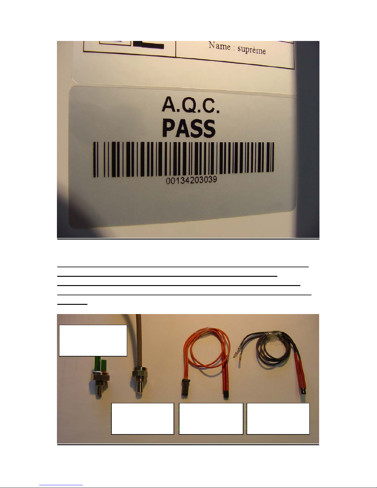
Important information on manufacturing coding
AQ PASS – Serial number
Artech – Espresso machine
000/0/00/00/000
Day – serial number
Year – (last two digits)
Production week in year
Day (1-7) of corresponding week
Customer reference number
Shown above is the previous coding system used up to week 47/2003. The 1
st
and 2nd digit groups were not
used.
After week 47, the coding shown below was introduced and is now the valid coding system.
00/00/000
Serial number
Year – (last two digits)
Production week of year
45
There are two different types of temperature sensors currently in use. As
from Wk 42-2003, the new, larger sensors were introduced. The
instructions that follow are valid for both types. The procedure for the
older type of sensor will be described first, and then the procedure for the
new one.
New sensor for bottom
heat exchanger
New sensor for top
heat exchanger
Old sensor for bottom
heat exchanger
Old sensor for top
heat exchanger
46
The hand tools that are essential for carrying out servicing on the Espresso
Machine are shown below and should always be part of your servicing kit.
In addition to screw key and two rachets, you will also need two
screwdrivers (one normal one and one with interchangeable bits) as well as
spanners for a range of widths: 10, 12, 13, 14, 15 and 17.
Step-by-step procedure
1. Firmly clutch and lift the handle on the spill-tray drawer, and gently slide the
Espresso machine out of its housing towards you. (Opening as for water and
coffee refilling or checking the grinder).

47
2. The upper front cover is screwed down with 6 countersunk screws. Unscrew and
remove all screws and take cover off.
3. With the cover removed, the next photo shows the view of the inside layout from
above.
Unscrew the six
countersunk screws
on the cover.
Then remove cover.

48
4. The following picture shows the top-positioned heat exchanger seen from above.
In the centre of the heat exchanger there is the water in-let pipe assembly
through which heated water under pressure passes. Top left >>at 10 O’clock<<
there is the earth connection with a brass seal under which the temperature
sensor (Minimum-Maximum operating temperatures- older installation layout)
can be found.
5. On the left side >>at 9 O’clock<< there is the reversible thermostat. In the
middle, between the two electrical connections, the reverse push button can be
seen (beige-brown). Test the thermostat by pushing in the button. Wait to see
what happens!
6. After the reverse push button has been set in the pushed-in position, close the
machine for testing (do not reassemble the top front cover!). Switch the machine
on following operating instructions. Wait until the top left and top right leds
(showing brewing water and hot water/steam temperature) remain alight. For
testing purposes, turn the knob on the front panel and check whether hot water is
delivered from the wand. In the event that the thermostat should be triggered
again, then the fault could be with the sensor on the corresponding heat
exchanger. In this case, disconnect power supply to machine and open it up.
7. Follow the photo sequence and explanation in the next section to replace sensor.
This procedure is for the >>old<< type of sensors.
T
op left, the top
thermostat. In the
centre there is the
beige-bown pushbutton
T
he sensor is
under the earth
cable

49
8. Unscrew the earth cable connection
9. Move both earth cables, the earth connection assembly, screw, and earth seal to
one side, and use the short insulation wires to take the defective sensor out of the
hole in the heat exchanger.
10. Now find a >>clear working space<< as the diagnostics and settings panel needs
to be disassembled. The panel is fixed on the outside by two screws underneath
on the right and on the left. First, remove knob on the right, then unscrew right
screw underneath and then left screw. See photos!
10/1 10/2

50
10/3
11. Now, inside the electronics panel, at the front on the far left remove the multiterminal plug and carefully lift it up as far as the wire will allow it to be lifted.
Now, make room in the lower area for the main circuit board. Look at the view
of the circuit board after the large plug has been removed:
Here you can see the plug (on the right, black wire) of the sensor that has just been
freed. From the front, carefully put your hand into the opening that has been created in
the housing and remove this plug and wire with the sensor attached through the gap,
lifting it >>over and out<< of the heat exchanger zone and into the electronic one (or,
alternatively, pull the wire into the heat exchanger zone).
If this does not resolve the problem, you need to >>make room<<for the next parts to be
disassembled. Remove the top cover. In detail, this entails removing the cover from the
coffee container, the filter at the end of the water tube and taking the tube out of the
cover (first, mark the tube so that it can be repositioned in its old position later). Now,
remove the water container and loosen all cover screws and remove cover. Empty the
coffee container. Remove transparent coffee container after having loosened both black
screws. Later, using the marking (on the left) replace.

51
See the following step-by-step photos:
Loosen all screws
Remove cover
Empty coffee storage container and after having loosened
the two screws, take it out. Now, the back screw fixing the
metal plate separating the heat exchanger and electronic
zones can be accessed. The front screw can be accessed
after having removed the switch cover. Loosen screws!
Multi-terminal plug has already been loosened.
Remove the two earth connections and the two primary
line wires (brown and blue) lying on L and N and the two
secondary line wires lying on 1 and 2. Take out the
dividing plate.
Now, it is possible to track the sensor connections that
need to be loosened to the electronic zone, loosen them
and lay a new one.

52
Plug socket for the two black
wires (adapter box) of the hot
water sensor
Plug socket for flatband connection
between main circuit board and front
switch circuit board.
Plug socket for the two red
wires (adapter box) of the
coffee brewing water sensor

53
12. If it was clear at the start of the repair that the sensor in the bottom heat exchanger
(responsible for Espresso coffee temperature) may also have a problem, then at this step
of the repair, the bottom sensor (old installation layout) should be replaced in any case.
This means that the top heat exchanger has to be completely disassembled, following the
procedure in the next section.
a. Disassemble the central water in-let pipe. Next, remove the flexible tube from the
elbow union (press ring on the union in the
direction of union and slide out tube in
opposite direction).
b. Work carefully when disassembling and reassembling the elbow union.
The thread on the elbow union is very delicate and can easily be ruined by over tightening. When reassembling, apply >>Loctite<< sealant to thread and tighten
>>gently<<.
Press ring in direction of elbow union
and slide out tube
First loosen top hex
nut using a >>SW 10<<
spanner turning
anti-clockwise.
Then loosen >> M8<<
nut and remover top
and under plates

54
Proceed with disassembly as follows
Remove the elbow union
Loosen M8 nut, remove
base plates
Place a hand under the
filter holder group
head and catch
diffuser as it drops
down
12. Now, it is time to disassemble the top heat exchanger. First, the two water
connections on the right-hand side need to be loosened. Both can be found on the
top heat exchanger. The back connection is made up of a brass fitting
arrangement, while the front one, under a curved connection, is a chrome union
fitting arrangement.
In the case of the brass fitting union, use the left large nut for support and loosen
the smaller right nut. In the case of the chrome union, the nut which is under the
elbow union should be loosened from the front through the window.
The photos show this procedure.

55
12/1 12/2 12/3
Photo 12/1 shows the loosening of the brass nut on the coffee heat exchanger water inlet.
Photo 12/2 and photo 12/3 show the loosening of the inbus screw (5th INBUS)
Photo 12/4 shows a front view through the window of the chrome union with the 180°
copper pipe elbow union.
Now that all connections have been unfastened, the top water heat exchanger can be
carefully removed.
Next, the bottom heat exchanger (for coffee brewing water) sensor can be changed that
is likewise in a „10 O’clock position“ under the earth screw.
Loosen the earth screw that holds the three incoming earth connections and take the
sensor with its two red wires out of the hole in the heat exchanger. Trace the connection
back to the main circuit board of the corresponding plug (on the left, red connection)
and remove.
T
his chrome union needs to be loosened

56
13/1 13/2
13/3
13. Photos 13 / 1 to 13/3 show the removal of the top heat exchanger and the freeing
of the bottom sensor connection. The sensor with the red wires is under the
insulation next to the earth screw.

57
14. Apply a quantity of heat conducting adhesive to the sensor with the red wire and,
likewise, fill the hole with a quantity of adhesive and push the sensor back into
the hole. Replace and press the insulation securely around both wires right up to
the black sensor casing (no direct contact should be made between the wire and
the heat exchanger shell or the earth wires and/or the earth screw). Both wires
should not be allowed to move around (short circuit).
15. Collect all earth connections using the short insulation band into the earth screw
and screw firmly into place. The sensor should be in a secure position and fixed
so that it is insulated. Next, lay the red wires in the direction of the electronic
circuit board and plug the AMP- plug into third plug slot (see photo).
Now check whether the reverse button is engaged on the bottom reversible safety
thermostat.
16. Next you need to completely reassemble the top heat exchanger. Follow this
procedure:-
a. Place the heat exchanger in the correct position and position both inbus
screws and screw up tight.
b. Reconnect water connections. Tighten well so that afterwards the pressure
connections are also sealed.
c. Replace the central tube with upper filter holder (check gasket and
carefully clean off any dried coffee deposits that may be on the filter and
in the gasket groove. Insert the rod with the threaded part at the top up
through the filter holder group head. Next, replace under plate and top
plate and tighten the M8 nut by hand. The secure, using the correct size
spanner secure.
Next, with the aid of >>Loctite 542<< sealant,
carefully place the elbow union on the inner thread
of the pipe and turn 1-1/2 times by hand. Then apply
a little >>Loctite 542<< and give it a few seconds to
take, then using a spanner carefully, >>gently<<
tighten. Do not force the thread!
Re-insert the tube in the elbow union. It will automatically be clasped in place by a
mechanical clipping mechanism.

58
Position the new >>hot water sensor<< with black wires, together with both earth wires
and the earth seal under the insulating tape. Caution: rub a quantity of conducting paste
on to this sensor and around the hole in the heat exchanger. When repositioning, push to
squeeze any excess adhesive and carefully wipe away. Next, insulate he single wires up to
the sensor casing and position so that no contact can be made between them and no
contact with the metal is possible.
17. The next section will explain how to replace the new sensors that were introduced
commencing from Wk 42 in 2003 with a view to making the disassembly and reassembly procedure to replace sensors easier.
The position and the type of sensors were changed. The hot water and steam
sensor is now positioned on the right-hand side near the top, on the top heat
exchanger in a „2 O’clock position“

59
18. Loosen the sensor using a suitable size spanner and screw out. Next remove the
plug from the main electronic circuit board (both size and position have been
changed) and pull out the whole cable in the direction of the sensor.
19. Lay the cable of the new sensor behind the heat exchanger, plug in AMP – miniplug to the corresponding plug slot in the main circuit board and using
conductive paste screw the new sensor back into the heat exchanger and tighten.
20. The coffee sensor (bottom heat exchanger) is likewise on the right-hand side of
the heat exchanger. It is however positioned below, at the front on the right, at „5
O’clock“ and in the current production series is somewhat difficult to access (in
the future, the “window” on the bottom right of the housing will be made larger,
to make handling easier).
The yellow two-headed
arrow shows the hot water
sensor. Loosen using a
suitable size spanner!
Shown is the sensor
for coffee water
temperature. In the
event that the nut
cannot be reached
with the spanner,
loosen the copper
elbow union at the
front and displace
to the right, thereby
creating room for
the sensor to be
accessed.
60
21. The photo on the next pages shows the view from the front looking on to the heat
exchangers. The bottom sensor must be loosened
with a spanner and screwed out. Both connecting
wires (slack running in front of the heat exchanger)
must be disconnected from the old defective sensor
and connected up to the connecting plugs of the new
sensor. With the aid of conducting paste position
the new sensor and screw firmly into place. Finally,
reposition the copper elbow union in its original
place and tighten up nut.
22. After the new sensors have been installed, (old and new procedure), the machine
can now be re-assembled:
a. Position the dividing plate with fitted filter (against electromagnetic
interference). All connecting wires that run between the heat exchanger
compartment and the electronics compartment must be carefully placed
in the gaps under the metal plate so that the metal plate can sit cleanly
underneath on the floor. Screw in the black screws in the grinder
compartment and on the front side fixing this plate in position.
Loosen nut (1) and (2) work
loose, displacing copper pipe
to the right.
Sensor
T
he sensor lies
behind this plate,
where the white
circles is, and
can be accessed
when the copper
pipe has been
displaced to the
ri
g
ht
1
2

61
b. Plug in both the primary line wires (brown and blue that run out of the
left side of the casing wall) to the L and N connection terminal. Plug in
both secondary line wires, brown from the circuit board to connection
terminal 1 and blue from the multi-terminal plug to connection terminal
2.
c. Plug in the flat band-cable connection from the switch circuit board to the
main circuit board in the red connecting strip.
d. Reposition the multi-terminal plug.
e. Position the front panel and screw in place with the two screws from
below.
f. Replace the knob on its pin and set in zero position.
g. Reposition the transparent coffee container on the grinder and screw in
place with the two black screws. Refill with coffee beans!
h. Refill water container and reposition. Provisionally dip water tube into
water.
i. Reconnect machine to mains for testing purposes and disengage the safety
switch (at the back, bottom left) with the aid of a piece of styrene, wood
or cardboard so that the machine is electrified.
j. Caution: Now do NOT touch any parts inside the machine! Keep people
away from the machine! All connections and plugs are under 230 volt
voltage. Electric shock hazard!
k. Switch machine on at front panel. A number of leds should be
permanently on. The leds top left and top right should now start to flash
and after approximately two minutes should likewise remain permanently
lit up.
l. Proceed following operating instructions and, after the previously flashing
leds are likewise permanently lit up, deliver both water and steam to the
wand and hot water to the brewing station.
m. During all processes, check again that all water connections which have
been loosened during this repair are >>tight<<. Should a problem be
found, immediately engage the safety switch and disconnect machine from
mains supply. Look into problem.

62
Servicing and Maintenance
Product: Espresso-Machine
Model: Semi-automatic, Built-in
Service Instruction: 8/04 Circuit Board replacement
Problem:
Semi-automatic processes are not functioning, which are normally
engaged by pressing the corresponding pad on the front control
panel. Problems may include:
● After pressing the grinder switch there is no reaction
● In spite of pressing the >>brew coffee<< pad, no water is delivered
to the brewing station ( water pump not working = no pump noise)
● When switch for >>steam<< and/or >>Water<< is pressed, there is
no reaction
● No reaction from the main on-off switch (First, move machine out
of its housing and manually activate safety switch. This switch can be
found at he back of the machine, bottom left-hand side) Further,
check whether the machine’s safety fuse system is o.k. It is positioned
on the side, top left)
● There is no reaction after having pressed >>one cup or two cups<<
pad and, likewise, >>short-medium-long Espresso<<
In correct working conditions, all function pads on being pushed should
immediately perform their relative tasks. The pre-set or individually set functions
should always be performed and delivered repeatedly in the same, standardised
way. If problems arise concerning these functions, which are not being delivered
in a standard way each time, or they are not working at all, then the following
checks should be carried out in the order given below:
● check the flat cable connection between die switch circuit board and main
circuit board, next check
● switch circuit board and, if the problem cannot be solved here, and the fault
still persists, then check
●the main circuit board
and replace with a new one. This instruction will illustrate how to replace both
circuit boards and the procedures will be described separately.

63
Cause:
a. The switch and/or relative indicator led may be defective. In this case
the circuit board needs to be replaced.
You can assume that the fault lies with the switch circuit board when
individual leds do not work (switch or led fault) or when no leds on the
circuit board light up (which however may also be due to no contact being
made with safety switch located at the back on the bottom left of the
machine or the machine safety fuse system being faulty – for example, due
to the grinder being overtaxed; attention, in this case, first look to see
whether any foreign bodies are obstructing the grinder movement!!) In the
above mentioned cases, you should concentrate on replacing the switch
circuit board, but first check to make sure that the flat-cable connection
running between the switch circuit board and the main switch board is
plugged in correctly.
b. The fault could be due to normal wear and use of the circuit boards; the
relative maintenance instruction highlights the importance of changing the
main circuit.
Before changing the main circuit board, check that the fault is not due to
the switch circuit board.
Solution:
To a.
The switch circuit board needs to be disassembled following the
procedure illustrated further on. However, first check that that the
cable on the circuit board is plugged in correctly and (when you have
checked) proceed to disassemble the switch circuit board from its
frame on the machine.
To b.
Please check that it is absolutely necessary to replace the main circuit
board as, in order to access it, an entire sector of the machine has to
be >>disassembled<<.
Before carrying out the required work procedures, please read the
following general notes and recommendations, and especially the
safety advice notes for service engineers, remembering to follow them
at all times.

64
Safety Advice for Service Engineers
Caution: Before commencing any work on the appliance, it should be “disconnected”
from the electricity supply. This can be done by:
either removing the appliance plug from the mains socket or by isolating electricity
supply to socket through safety circuit-breaker or by turning off electricity completely
at mains switch.
Caution: For the purpose of simply carrying out testing and checking of the machine,
the Service Engineer may leave the machine connected to the mains power supply when
there the approved electrical safety breaker device installed at the back, in the left-hand
bottom corner of the machine (that cuts out power supply in all directions between
appliance socket and appliance electrical circuit) is manually activated and cuts out
mains power to the machine.
As an authorised Service Engineer, you should comply with all European testing
standards and the relevant safety regulations for electrical appliances, in order not to
endanger yourself or other people and to prevent any other kind of hazards and risks.
For this electrical appliance, due to various systems that contribute to the working of the
machine, it is important that you observe and take note of the technical specifications of
the machine which include:
Power supply: 240 Volt mains
Heat exchanger and operating pressure up to 15 bar
Water containers and water conducting pipes (some under pressure)
High temperatures in water conducting system and heat exchangers
Only authorised Customer Service Engineers are allowed to carry out work on this
Espresso machine (the opening of parts of the machine that are secured by screws).
European testing and safety regulations should always be complied with when carrying
out work on the appliance.
The appliance manufacturer and the Servicing firm shall not be liable for work carried
out that is not conformant with test an safety regulations and, likewise, tampering or
work carried out by unqualified servicing firms and local service engineers.

65
Important production series information:
AQ PASS – Serial number
Artech – Espresso machine
000/0/00/00/000
Day – serial number
Year – (last two digits)
Production week in year
Day (1-7) of corresponding week
Customer reference number
Shown above is the previous coding system used up to week 47/2003. The 1
st
and 2nd digit groups were not
used.
After week 47, the coding shown below was introduced and is now the valid coding system.
00/00/000
Serial number
Year – (last two digits)
Production week of year
Please always quote the appliance number when dealing with our service
department!!!!!!!!

66
The hand tools that are essential for carrying out servicing on the Espresso
Machine are shown below and should always be part of your servicing kit.
In
addition to 5 mm screw key ( for disassembling the heat exchanger)and two
rachets, you will also need two screwdrivers (one normal one and one with
interchangeable bits) as well as spanners for a range of widths: 10, 12, 13,
14, 15 and 17.
General procedure:
1. Firmly clutch the handle on the spill-tray drawer, and gently slide the Espresso
machine out of its housing towards you. (Opening as for water and coffee refilling or
grinder selection).

67
2. The upper front cover is screwed down with 6 countersunk screws. Unscrew and
remove all screws and take cover off.
3. With the cover removed, the next photo shows the view of the inside layout from
above:
4. The following picture shows the top-positioned heat exchanger seen from above. In
the centre of the heat exchanger there is the water in-let pipe assembly through
which heated water under pressure passes. Top left >>at 10 O’clock<< there is the
Unscrew the six
countersunk screws
on the cover.
Then remove cover.

68
earth connection with a brass seal under which the temperature sensor (MinimumMaximum operating temperatures) can be found.
5. On the left side >>at 9 O’clock<< there is the reversible thermostat. In the middle,
between the two electrical connections, the reverse push button can be seen (beigebrown). This push button must be in the pushed-in position.
Wait and see what happens! If the thermostat is working correctly, go directly to
point 8 of this section (changing the circuit board).
6. After the reverse push button has been set in the pushed-in position, close the
machine for testing (do not reassemble the top front cover!). Switch the machine on
following operating instructions. Wait until the top left and top right leds (showing
brewing water and hot water/steam temperature) remain alight. For testing
purposes, turn the knob on the front panel and check whether hot
water is delivered
from the wand. In the event that the thermostat should cut out again, then the fault
could be with the sensor on the relative heat exchanger. In this case, disconnect
power supply to machine and open it up.
7. Follow the special instruction for changing the sensor. Contact your servicing firm.
8. Now find a >>clear working space<< as the diagnostics and settings panel needs to be
disassembled.
On the left, the top
thermostat. Centre,
the reverse push
button.
T
he sensor is
under this
earth
connection

69
9. The panel is fixed on the outside by two screws underneath on the right and on the
left. First, remove knob on the right, then unscrew right screw underneath and then
left screw. See photos! Remove panel.
9/1 9/2
9/3
10. Now check that the flat cable connection is plugged in correctly. To do this, unscrew
the four screws that hold the circuit board in its frame( 10/1) and remove the circuit
board carefully from its mounting. You can now see the top side of the circuit board
(10/2) and you can check whether the flat cable is connected properly.
10/1 10/2

70
11. Having verified that the switch-circuit board cable connection is sound, you now
need to be check switch-side that there is no problem. Trace the flat cable back
through the left side of the compartment, and, by carefully moving the various cables
that lead to the main circuit board to one side, you will see a small red plug on the
main circuit board.
We would recommend that you remove the large 8-plug terminal (power supply to
main circuit board, so that you have a free view of what is below the circuit board
and can check the connection of the mini-plug (flat cable)). See the photos below:
11/1 11/2
11/3 11/4
11/5

71
12. Once you have checked that the cable connection between main and switch circuit
board is sound and, likewise that problems are not being caused due to a break in
the cable or a bad connection, replace the circuit board. First, remove plugs from old
circuit board and plug them into the new one in the same way.
Now, manually close the safety switch and holding the switch circuit board around
the edges, press the lower left pad (on-ff switch. It works? If yes = go to point 13 of
this section. If no =go to point 18 of this section).
13. As far as it can now be seen, having replaced the old circuit board with a new one,
the machine functions appear to be working. Re-engage the safety switch to exclude
power to machine and re-assemble the new circuit board in its casing.
When repositioning the circuit board in its frame, proceed with caution and move
the switch pads and leds very carefully to reposition them. If required, bend the leds
very gently. Do not use force! Caution: breakage and damage hazard!
14. After the circuit board has been mounted in the switch control panel, replace the
front panel and screw tight from below. However, first make sure that the flat cable
is sitting unobstructed at the back.
15. Reconnect the 8-pole plug terminal to the main circuit breaker.
16. Next, test run the machine; replace the upper cover but do not screw into place. Fill
coffee grinder hopper and water container.
17. Reposition in its housing (the safety switch should be at the end position so that
power is delivered to machine). Switch the machine on. Let the machine warm up.
When the initially flashing leds for >> hot water<< (or steam) und >>coffee
brewing<< remain permanently on, it is possible to carry out a complete check of all
functions. Follow operating instructions.
When al machine functions are working correctly, the upper cover can be screwed
back into place. The repair has been successfully carried out.
If not all machine functions are working or processes are irregular, then the main
circuit board needs to be replaced; in this case, move onto point 18 to review the
procedure for replacing the main circuit board.
18. Installing a new main circuit board.
If, after having replaced the switch circuit board, not all functions are working
correctly, and, in particular, the initial fault still has not been resolved, then the main
circuit board needs to be replaced. To replace the main circuit board a significant
section of machine needs to be disassembled. Therefore, make sure you have a good,
clear working space.

72
As before, remove the upper front cover. This means: remove cover from coffee
container, remove cover from water container and the filter in the end of the water tube,
remove tube from the cover (first mark the position on the tube with a piece of tape
where it enters the cover opening so that it can be replaced in the same position later),
remove water container and unscrew all cover screws. Remove cover. Empty coffee
container. Once emptied, remove the two black screws on the base of the transparent
coffee hopper. When re-assembling, remember to reposition the hopper with the mark
on the rim facing left.
See the following photo sequence:
Loosen all screws
Remove cover
Empty coffee hopper and after unscrewing two black
screws, remove. Now the back screws fixing the plate that
divides the heat exchanger zone from the electronic one can
be accessed. The front screw is already accessible after
having removed the front switch panel. Loosen screws!
The multi-pole plug terminal should have
already been unplugged
Disconnect the two earth wires, the two primary line
wires (brown and blue) that are connected to L and N
and the two secondary line wires (brown and blue) that
are connected to 1 and 2 on the ELMAG filter. Remove
dividing plate.
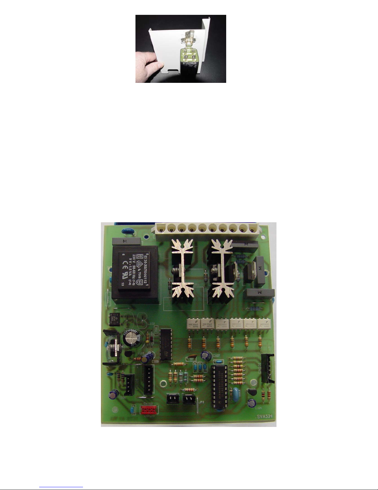
73
Now, it is possible to access the electronics zone more freely and follow the connections;
disconnect them and re-lay them when the new main circuit breaker has been installed.
19. After the transparent coffee hopper has been removed, the plastic spring clips are
now accessible that hold the main circuit board in place in the dividing wall between
the front and back machine sections. Using a small pair of pincers, squeeze the clips
one by one and ply out of the main circuit board through the holes. The clips remain
attached to the circuit board. When they are squeezed, the entire board can be
moved and can be carefully taken out.
Now disconnect the single plugs in total five cable plugs), plus the eight-pole plug
terminal, which has already been unplugged and then plug in all plugs in reverse
order to the new main circuit. Using the spring clips, reposition the new main circuit
board. Handle the flat cable that leads to the switch circuit board very carefully and
secure.

74
20. After having successfully made all connections on the new circuit board and fixed
the spring clips so that that the new circuit board can be carefully re-positioned in its
seating, finally insert the individual clips through the holes to secure the assembly.
21. Press the dividing plate with the ELMAG filter back into place (Caution: position all
cables so that they lay left to right in the gaps in the dividing wall. Do not cause any
cable to be obstructed!) and screw into place front and back. Plug in plugs according
to switch layout drawing.
22. Reconnect main plug terminal (eight-pole).
23. Re-assemble transparent coffee hopper and screw in place. Replace and position the
water pipe through the opening in the back cover and re-insert water container.
Replace filter and reposition the tube through the blue cover using the tape mark to
make sure that it will occupy the same position as before.
24. Screw back cover into place. Screw front cover into place. Screw the front panel into
place ( unless this was done previously).
25. Test run the machine.
26. If, in spite of having replaced the main circuit board, the machine is still troubled by
the same problem, then the Espresso machine will have to be sent back to the factory
for further trouble-shooting.
In this case, contact the customer care center at the factory to make transport
arrangements and to explain what assistance may be required.

75
Servicing and Maintenance
Product: Espresso-Machine
Model: Semi-automatic, Built-in
Service Instruction: 9/04 Water pump/water pipe
Problem:
The water pump is very noisy (running without water) and hot water
and brewing water are being delivered slowly because there is a
problem with water flow between the water container and the heat
exchanger.
Under correct working conditions, the water pump starts running after a brief
>>loud<< start-up noise and then progressively becomes quieter. Routinely,
water should flow from the water container through the flowmeter, the
distribution and stop valves and through the heat exchanger and a normal
operating noise level should be heard. When there is a fault, the first symptom is
a change in noise, which progressively becomes a loud >>rattling<< sound. This
means the pump is operating without water.
Cause:
a. The water conducting pipe between the water container and flowmeter
is badly positioned or has a kink. The quantity of water required by
the pump is not being delivered. The pump is running on insufficient
water and is becoming noisy.
b. There maybe an obstruction in the water flow system, or a general
>>furring up<< that leads to insufficient water being delivered to the
pump.
c. The pump is faulty due to having >>run<< on insufficient water
causing overheating.
Solution:
To a.
Get rid of any kinks in the pipe (that can generally be seen by looking
through the entry hole in the back cover) by jiggling the section of the
tube between the blue cover of the water container and the flowmeter.
It may also be an idea to replace the in-let tube (leading from water
container to flow meter) with the newer, „second generation“ tubes
(harder and less prone to kinking).
You should then test the water flow system. This means water flow to
the Espresso brewing station (press the coffee brewing pad on the top
left of the control panel) and also water to the wand; press >>hot
water/steam<< and >>hot water<< or >>dry steam<< following

76
operating instructions. During this operation the >>Water pump<<
normally works quietly pumping sufficient water out of the tap
station.
Checking procedure: (Caution
: this should only be carried out by a
service engineer if required during servicing!!!) The movement
required is like that for coffee or water servicing, pull out the
machine (lift up drawer handle and pull forward) and on the lefthand side, at the back of the machine, manually activate the safety
switch so that the machine is connected to electricity supply. Next,
(place a container under the water tap!). Press the top left pad (brew
coffee) and look into the back section between the blue water cover
and the entry hole and check whether water is flowing. See photo!
Carefully jiggle the tube left and right to eliminate any kinks that
might be along the tube (which cannot be seen because it is behind the
casing).
If sufficient water is not being delivered, and the pump appears to be
working >>normally<< = see b.
To b.
Following the procedure in the operating instructions and carry out a
de-furring cycle! General system maintenance carried out by endcustomers is a requirement, without which they are liable to pay the
costs.
To c.
Replace the pump, following the procedure outlined in this section.

77
Safety Advice for Service Engineers
Caution: Before commencing any work on the appliance, it should be “disconnected”
from the electricity supply. This can be done by:
either removing the appliance plug from the mains socket or by isolating electricity
supply to socket through safety circuit-breaker or by turning off electricity completely
at mains switch.
Caution: For the purpose of simply carrying out testing and checking of the machine,
the Service Engineer may leave the machine connected to the mains power supply when
there the approved electrical safety breaker device installed at the back, in the left-hand
bottom corner of the machine (that cuts out power supply in all directions between
appliance socket and appliance electrical circuit) is manually activated and cuts out
mains power to the machine.
As an authorised Service Engineer, you should comply with all European testing
standards and the relevant safety regulations for electrical appliances, in order not to
endanger yourself or other people and to prevent any other kind of hazards and risks.
For this electrical appliance, due to various systems that contribute to the working of the
machine, it is important that you observe and take note of the technical specifications of
the machine which include:
Power supply: 240 Volt mains
Heat exchanger and operating pressure up to 15 bar
Water containers and water conducting pipes (some under pressure)
High temperatures in water conducting system and heat exchangers
Only authorised Customer Service Engineers are allowed to carry out work on this
Espresso machine (the opening of parts of the machine that are secured by screws).
European testing and safety regulations should always be complied with when carrying
out work on the appliance.
The appliance manufacturer and the Servicing firm shall not be liable for work carried
out that is not conformant with test an safety regulations and, likewise, tampering or
work carried out by unqualified servicing firms and local service engineers.

78
Important production series information:
AQ PASS – Serial number
Artech – Espresso machine
000/0/00/00/000
Day – serial number
Year – (last two digits)
Production week in year
Day (1-7) of corresponding week
Customer reference number
Shown above is the previous coding system used up to week 47/2003. The 1
st
and 2nd digit groups were not
used.
After week 47, the coding shown below was introduced and is now the valid coding system.
00/00/000
Serial number
Year – (last two digits)
Production week of year

79
The hand tools that are essential for carrying out servicing on the Espresso
Machine are shown below and should always be part of your servicing kit.

80
In addition to 5 mm screw key ( for disassembling the heat exchanger)and
two rachets, you will also need two screwdrivers (one normal one and one
with interchangeable bits) as well as spanners for a range of widths: 10, 12,
13, 14, 15 and 17.
General procedure:
1. Firmly clutch the handle on the spill-tray drawer, and gently slide the Espresso
machine out of its housing towards you. (Opening as for water and coffee refilling
or grinder selection).
2. The upper front cover is screwed down with 6 countersunk screws. Unscrew and
remove all screws and take cover off.
Unscrew the six
countersunk screws
on the cover.
Then remove cover.

81
3. With the cover removed, the next photo shows the view of the inside layout from
above:
If you need to >>create more room<< to prepare for changing the tube and/or pump,
you will need to remove the top back cover. This means: remove cover from coffee
hopper, remove cover from water container, remove filter from end of tube and remove
tube from the cover (first mark the position on the tube with a piece of tape where it
enters the cover opening so that it can be replaced in the same position later), remove
water container and unscrew all cover screws. Remove cover.
4. See the following photo sequence:
Loosen al screws on top back
cover
Remove blue cover and then
back cover with tube.

82
In the photos on the left
and right, you can see the
Flowmeter;
Remove in-let tube (water
from water container) and
attach a new, more robust
tube of a suitable length.
As a precaution, check the
flowmeter.
Turn the cover of the
flowmeter from >>9
O’clock<< to >>8
O’clock<<
(Bayonet-coupling).
Carefully remove cover.
Do not lose red seal
Check whether the small
impeller wheel with
magnets turns freely. If
yes, replace cover and turn
clockwise to lock.
5. Now, you need to >>free up<< a further section of the machine to proceed with
changing the pump. Firstly, the front control panel needs to be disassembled. This
can be done by removing the two screws, on the right and left, under the panel.
Remember to remove the knob first. Remove right screw then the left one. See
photos!

83
CAUTION: When placing the switch panel to one side, make sure that the
flat cable does not become disconnected from the plug mounting on the
main and switch circuit boards. Do not pull unnecessarily!!!!!!!!!!!!!!!
6. Now the pump can be disassembled from the machine. Follow the step-by-step
procedure shown below:
Through the front >>housing panel window<<, on the
right, disconnect the water in-let pipe to the pump using
a suitably-sized spanner
And remove.
Next, loosen the fixing screws on the two rubber pump
clamps. From below, hold onto the butterfly nut and
from above loosen the two socket head screws.

84
Remove the connecting tube from the flowmeter.
Next disconnect the electrical connections from the
pump. See the next photo sequence:
Make a note of the
connections:
a. blue x2 = left
b. red x1 = right
and remove cable and pump.
Now, with the pump out of the machine, remove pipe.
Next, using a size 12 and size 10 spanner loosen the
brass elbow union on the other side of the pump
(caution: a significant amount of force will be needed
to do this).
Then remove the rubber supports on both sides and place on new pump.
Next, remove the two plastic
caps (put on by manufacturer to
prevent dirt from entering
pump).
Then remount the brass elbow union on the new pump and tighten using maximum
force. Later, when you test the machine (not having fixed the upper cover in place),
check that this connection is >>water tight<<. If absolutely necessary, retighten or
loosen connection and wrap a sealing band around the outer thread of the elbow union
(this should only be done as an exception not as a rule!!!!!).

85
7. Now, reinstall pump in machine, laying the in-let pipe at the back and into the
flowmeter area. Re-connect electrics to flowmeter (two blue and one red). Position
pump and, again holding the butterfly nut, tighten socket head screws.
8. Attach the high-pressure water pipe using the brass screw band and tighten so that
it is >>water tight. Connecting clamp.
When all connections have been made, you can remount
the front machine panel and replace the knob so that
you can better observe how the machine>>handles<< .
Next, >>only to be carried out by service engineer<<
switch off the safety switch and jam fast. Now the whole
machine is electrified!!!!!!!
Switch the machine on and let it warm up (temporarily position and fill water
container).
Caution: in this situation there is an electric shock hazard, and particular caution
should be used when working. Do not touch any electricity-conducting components
inside the machine. Also various components heat up significantly and therefore should
not be touched to prevent burn hazards.
Keep all unnecessary persons away from machine!!!!!!!!
When both the water and coffee temperature leds stop flashing (leds to right and left),
test the machine following operating instructions.
It is important to allow the new pump to draw in mains water supply. First place a
bucket under the water tap and open tap by pushing lever in an anti-clockwise direction.
The pump should run and water from the water container should start to flow through
the system, the valves and the heat exchanger. As soon as the system has been filled and
water is following out of the water nozzle, the pump should be generating normal (not
rattling) noise.
In the case that water supply is not sufficient or the pump continues to make a loud,
rattling noise, and another cause for this cannot be identified, then you should contact
customer service and send a report to the customer service center for advice on how to
resolve the problem.
After testing, if the pump is working without any problems, you can now complete reassembly of the machine.
This is the procedure:
a. Disconnect electricity supply to machine! Release the safety switch at the back of
the machine on the left-hand side.
b. Check everything one more time and remove the water container once again.

86
c. Replace back cover. Now, re-insert the new, harder water tube through the
opening in the cover and when replacing the cover make sure that the tube has
no kinks. Screw back cover into place.
d. Replace coffee cover.
e. Re-insert the water tube through the opening in the blue water container cover
(up to the taped mark) and re-insert filter in the end.
f. Fill water container, reposition and replace cover. Position the tube so that is lies
flat, but with no kinks, in the section between the opening in the metal cover and
the opening in the blue cover. It should not be obstructed or get caught up in any
way when the machine is pushed back into its housing.
g. Replace front upper cover and screw in place.
h. Re-house machine, switch on and run a full test cycle following operating
instructions.

Safety Advice for Service Engineers
Attention: Before commencing any work on the appliance, it should be “disconnected”
from the electricity supply. This can be done by:
either removing the appliance plug from the mains socket or by isolating electricity
supply to socket through safety circuit-breaker or by turning off electricity completely
at mains switch.
Attention: For the purpose of simply carrying out testing and checking of the machine,
the Service Engineer may leave the machine connected to the mains power supply when
there is an approved electrical safety breaker device installed at the back in the lefthand bottom corner of the machine (that cuts out power supply in all directions between
appliance socket and appliance electrical circuit) and he has this on hand and can
activate it.
As an authorised Service Engineer, you should comply with all European testing
standards and the relevant safety regulations for electrical appliances, in order not to
endanger yourself or other people and to prevent any other kind of hazards and risks.
For this electrical appliance, due to various systems that contribute to the working of the
machine, it is important that you observe and take note of the technical specifications of
the machine which include:
Power supply: 240 Volt mains
Heat exchanger and operating pressure up to 15 bar
Water containers and water conducting pipes (some under pressure)
High temperatures in water conducting system and heat exchangers
Only authorised Customer Service Engineers are allowed to carry out work on this
Espresso machine (the opening of parts of the machine that are secured by screws).
European testing and safety regulations should always be complied with when carrying
out work on the appliance.
The appliance manufacturer and the Servicing firm shall not be liable for work carried
out that is not conformant with test an safety regulations and, likewise, tampering or
work carried out by unqualified servicing firms and local service engineers.

>> Technical layout diagram<< of ARTECH- Espresso-Machine >>SUPRÈME<<
This is a semi-automatic model, in which coffee grinding (directly into the filter holder) is
separate from Espresso coffee delivery. All functions are automatic and have been preset; settings than can be changed (quantity of water and coffee can be programmed):
1. Espresso delivery After the filter holder has been filled with ground coffee the filter
holder is locked into the group head and the >>coffee<< button is pushed. Via the Water
pump (5) water is pumped out of the Water container (7) and flows over a Water batching
server (6) that will deliver the exact amount of water according to the setting. Water
passes through the heat exchanger (1) where it is heated under pressure. Water then
flows over the three-way tap to the open coffee solenoid valve (3) and then through the
system to the duct pipe which leads to both heat exchangers and eventually to the filter
holder. The water/steam solenoid valve (4) during this process remains closed.
2. Hot water or water-steam delivery When the Water/steam solenoid valve (8) is opened,
the Water pump (5) pumps water into the heat exchanger (1), then (for further heating)
to the three-way tap and through the solenoid valve (4) to the water and steam heat
exchanger (2) where, it then flows to the water/steam valve (8) and then, for example, to
the wand.
Filter holder
Coffee heat exchanger
Water + steam heat exchanger
Coffee solenoid valve
Water + steam solenoid valve
Water pump
Flowmeter
Water container
Water + steam valve
Steam nozzle

MODEL : SUPREME
HYDRAULIC DIAGRAM
water container fluxmeter pump
steam tap
steam
heat exchanger
solenoid valve solenoid valve
coffee
heat exchanger
water /coffee basin

10.
9.
8.
WIRING DIAGRAM - MODEL SUPREME
1. CURRENT PLUG
2. CABLE FIXING
3. SECURITY SWITCH
4. FILTER
5. WATER/STEAM HEAT EXCHANGER
6. COFFEE HEAT EXCHANGER
7. WATER PUMP
8. GRINDER MOTOR
9. WATER/STEAM SOLENOID VALVE
10. COFFEE SOLENOID VALVE
11. LIGHTNING
12. POWER CARD
13. COFFEE TEMPERATURE SENSOR
14. WATER/STEAM TEMPERATURE SENSOR
15. KNOB SWITCH
16. WATER FLUXMETER
17. COFFEE SENSOR
18. WATER SENSOR
2.
1.
7.
6.
5.
11.
3.
4.
12.
14.
13.
18.
17.
16.
15.
 Loading...