

Page 1

Operation and Installation manual
THISION WH
02/2011 DOC3078 / 12103187
Page 2

Page 3

Contents
Contents .................................................................. 3
General regulations ................................... 5
Application ................................................. 5
Norms and regulations .............................. 5
Construction Layout of water heater ............................... 7
Operating principle .................................... 7
Technical data ................................................................. 10
Water heater Installation .......................... 12
Connecting the water heater .................... 12
Commissioning Water and hydraulic system ...................... 17
Gas supply ................................................ 18
........................... 18
Flue and air intakeconnections ................. 18
Prepare water heater for first startup ........ 19
Combustion analysis ................................. 20
........... 21
Gas tightness check .................................. 21
Water heater shut down ............................ 21
Maintenance Checklist .................................................... 25
Replacing the electrodes ........................... 25
Cleaning the condensate receptacle ......... 26
Cleaning and refilling the syphon .............. 26
Inspection of the combustion chamber ...... 26
Water pressure and quality ....................... 27
Combustion analysis ................................. 27
Gas pressure ............................................. 27
Gas tightness check .................................. 27
Safety devices ........................................... 27
Maintenance Protocol ................................. 28
Loc
kouts
.................................................................. 22
Safety Provisions ...................................... 6
Thision WH principle ................................. 7
Unvented Applications .............................. 14
Cylinder diagnosis & controls .................... 19
Commissionign protocol ............................. 29
3
Condensate connections
Check functionality of safety devices
Cylinder venting .........................................
17
Page 4

Page 5

Safety
General regulations
Application
Norms and regulations
5
General regulations
This documentation contains important
information, which is a base for safe
and reliable installation, commissioning
and operation of the THISION L boiler.
All activities described in this document
may only be excecuted by authorized
companies.
Changes to this document may be effected without prior notice. We accept
no obligation to adapt previously delivered products to incorporate such
changes.
Only original spare parts may be used
when replacing components on the
boiler, otherwise warranty will be void.
Applic
ation
The THISION water heater may be
used for hot water production purpo-
ses only.
Norms and regulations
When installing and operating the
boiler, all applicable norms (european
and local) should be fulfilled:
Local building regulations for installing combustion air and flue gas systems;
Regulation for connecting the water
heater to the electrical appliance;
Regulations for connecting the water
heater to the local gas network;
Norms and regulations according to
safety equipment for heating systems;
Any
additional local laws/regulations
with regard to installing and operating
heating systems.
Additional national standards
Germany:
RAL - UZ 61 / DIN 4702-8
Switzerland:
SVGW
EKAS-Form. 1942: Flüssiggas-
Richtlinie Teil 2
Vorschriften der kantonalen Instanzen
(z.B. Feuerpoilizeivorschriften)
Netherlands:
GASKEUR BASIS
GASKEUR SV
GASKEUR HR107
Belgium:
HR TOP
The THISION L boiler is CE approved
and applies to the following European standards:
92 / 42 / EEC
Boiler efficiency directive
2009 / 142 / EEC
Gas appliance directive
2006 / 95 / EEC
L
ow voltage directiv
e
2004 / 108 / EEC
EMC directive
EN 483
Gas-fired central heating boilers Type C boilers of nominal heat input
not exceeding 70 kW
EN 15420
Gas-fired central heating boilers Type C boilers of nominal heat input
exceeding 70 kW, but not exceeding
1000 kW
EN 15417
Gas-fired central heating boilers Specific requirements for condensing
boilers with a nominal heat input
greater than 70 kW but not exceeding
1000 kW
EN 50165
Electrical equipment of non-electri
c
appliances for household and similar
purposes - Safety requirements
EN 15502-1
Gas-fired central heating boilers Part 1: General requirements and
tests
EN 55014-1 (2000)
Electromagnetic compatibility - Requirements for household appliances,
electric tools and similar apparatus Part 1: Emission
EN 55014-2 (1997)
Electromagnetic compatibili
ty - Requirements for household appliances,
electric tools and similar apparatus Part 2: Immunity - Product family
standard
EN 61000-3-2 (2000)
Electromagnetic compatibility (EMC) Part 3-2: Limits - Limits for harmonic
current emiss
ions (equipment input
current 16 A per phase)
EN 61000-3-3 (2001)
Electromagnetic compatibility (EMC) Part 3-3: Limitation of voltage
changes, voltage fluctuations and
flicker in public low-voltage supply
systems, for equipment with rated
current 16 A per phase and not subject to conditional connection
EN 60335-1 (2002)
Household and similar electrical appliances - Safety - Part 1: General requirements
EN 60335-2-102 (2006)
Household an similar electrical
appliances: Particular requirements
for gas, oil and solid-fuel burning appliance
s having electrical connections
Page 6

Safety Provisions
Conditions
It is a statutory requirement that all gas appliances are installed in accordance with the manufactures instructions and
all current regulations in force, all instructions should be fully read before installing or using the appliance.
All installations should be carried out by competent persons as described in the Gas Safety (Installation & Use)
Regulations. i.e. GasSafe registered and holding current certification.
The work must be carried out by a competent person as described in the I.S. 813 Domestic Gas Installations with
reference to the following codes of practices.
The Manufacturers instructions MUST NOT be taken in any way as overriding statutory obligations.
This boiler has been tested and certified to comply with all necessary European directives, latest building regulations
and efficiency requirements for the SEDBUK scheme and as been approved with an efficiency band rating of A and
is CE marked and
complies with
92
/42/EEC Efficiency of Hot Water Boilers Directive
90/396/EEC Gas Appliance Directive
93/68/EEC Low Voltage Directive (was 73/23)
92/31/EEC Electromagnetic compatibility Directive
I.S. 813 Domestic Gas Installations
The Thision WH should be installed in compliance with
The building regulations (Scotland-consolidated)
Building Regulations (Northern Ireland)
Building Regulations
Water fittings regulations or water bylaws in Scotland
Local water company bylaws
The boiler should not be modified in any way. Any modifications will invalidate the gas approval and invalidate the warranty.
ATTENTION: High Voltage
Before opening the boiler casing for maintenance or servicing the 230VAC main supply to the boiler must be
disconnected!!
5
6
Page 7
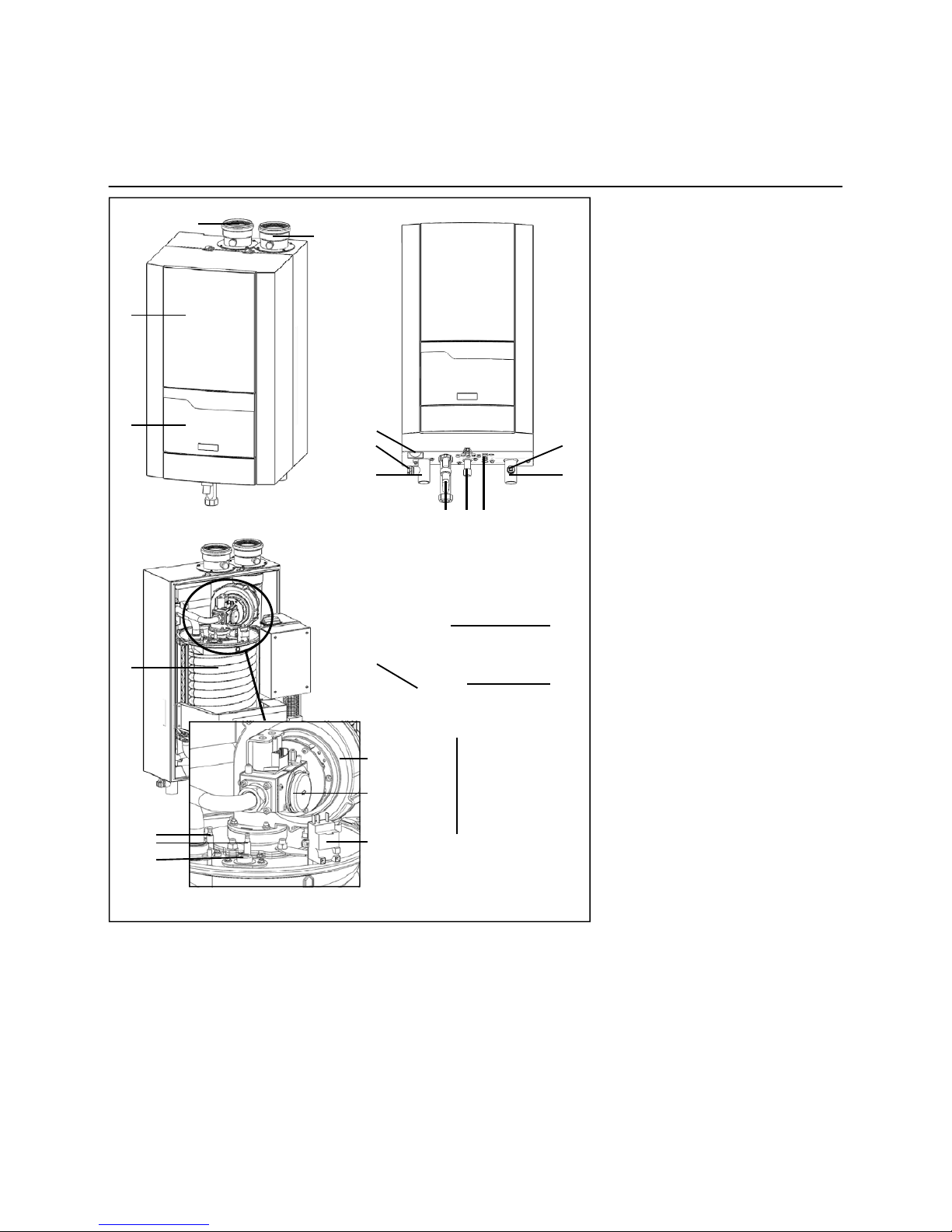
Construction
Layout of water heater
Operating principle
Layout of water heater
The THISION water heater consists
following main components:
1 Casing
2 Control panel
3 Flue gas connection (+ test point)
4 Air intake connection (+ test point)
5 Flow water connection
6 Return water connection
7 Gas connection
8 Syphon
9 Input for wiring
10 Connection for safety valve
11 Connection for fill/drain valve
12 Manometer
13 Fan
14 Gas valve
15 Ignition and ionisation electrodes
16 Heat exchanger
17 Inspection window
18 Ignition transformer
19 Electrical input connections
20 Controller
21 Condensate receptacle
Operating p
rinciple
The THISION WH is a fully modulating
water heater. The control unit of the
water heater adapts the modulation
ratio automatically to the heat demand
required. This is done by controlling the
speed of the fan. As a result, the whirlwind mixing system will adapt the gas
ratio to the chosen fan speed, in order to
maintain the best possible combustion
figures and therewith the best efficiency.
The flue gases created by the combustion
are transported downwards through the
heat exchanger and leave the boiler at
the top into the
chimney connection.
The return water from the system enters the boiler in the lower section,
where is the lowest flue gas temperature in the boiler. In this section condensation takes place. The water is
being transported upwards through the
heat exchanger, in order to leave the
boiler at the flow connection. The cross
flow working principle (water up, flue
gas down) ensures the most efficient
combustion results.
2
4
1
3
6 5
8 7
9
10 11
12
13
14
15
16
17
18
19
20
21
2
7
of the
Page 8
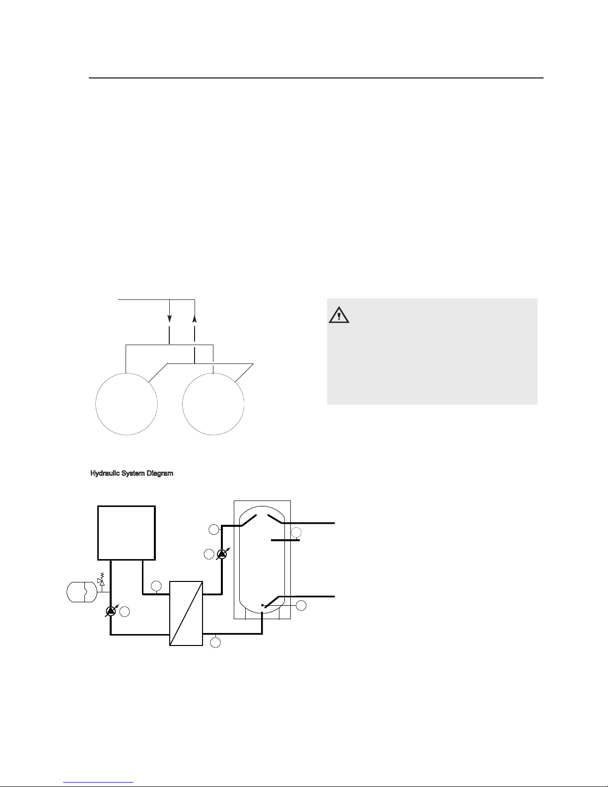
The Thision WH is a standalone DHW charging system that
consists of a buffer tank, plate heatexchanger and a boiler.
The System is suitable for use in any building with
medium to large water usage, such as swimming pools,
gyms , sports clubs, fitness centres etc.
Hydraulic System Diagram
The Thision WH is a standalone unit that functions exceptionally.
Where there is a high demand for hot water there is an option
to connect two units together in parallel. It is essential that the
units are connected such that flow is distributed evenly through
both units
Caution!
The capacity of the built in water recirculation pump is
600 l/hr at the 20 kPa setting. The maximum loss of the
flow and recirculation system occurs at 65°C flow and
60°C return (3.kw). A greater loss will cause a lower
return temperature and therefore a longer loading
period.
Legend:
P1: Loading Pump
P2: Boiler Pump
T1: Loading Temperature Sensor
T2: Start Temperature Sensor
T3: Shut Down Temperature Sensor
T4: Primary Flow Temperaure Sensor
T5: Secondary Return Temperature Sensor
(optional sensor required)
Ensure that pipework is equal from both units to the
secondary flow and secondary return connection.
Thision Thision
Plan View of two Thisions in parallel
The Thision WH has been designed for ease of installation. For
the unit to provide DHW a minimum of the following is
required to be installed from the system to the unit:
1. 230Vac electrical supply
2. Mains cold water supply
3. DHWS secondary flow pipework
4. DHWS secondary return pipework
5. Gas supply pipework
6. Condense drain pipework
7. Flue gas outlet & Air intake pipework
8
Thision WH
Installing 2 Thision WH in parallel
T2
T5
T3
T4
T1
P1
P2
Secondary Return
Connection
Page 9

Technical data
9
65
THISION L
85
THISION L
120
Nominal heat output at 80-60ºC max/min
kW 60.8/10.1 81.1/13.4 111.6/18.7
Nominal heat output at 75-60ºC max/min
kW 60.9/10.1 81.3/13.4 111.8/18.7
Nominal heat output at 40/30ºC max/min
kW 63.9/11.1 85.3/14.8 120.0/20.6
Nominal heat input Hi max/min
kW 62.4/10.4 83.3/13.8 114.3/19.2
Efficiency at 80/60ºC
% 97.4 97.4 97.6
Efficiency at 40/30ºC % 102.4 102.4 105.0
Annual efficiency (NNG 75/60ºC)
% 106.2 106.2 106.2
Annual efficiency (NNG 40/30ºC)
% >110 >110 >110
Standstill losses (T
water
= 70ºC) % 0.20 0.20 0.20
Max. condensate flow
l/h 3.5 4.8 7.7
Gas consumption H-gas max/min (10,9 kWh/m
3
) m3/h 5.7/1.0 7.6/1.3 10.5/1.8
Gas consumption L-gas max/min (8,34 kWh/m
3
) m3/h 7.5/1.2 10.0/1.7 13.7/2.3
Gas consumption LPG. max/min (12,8 kWh/kg)
kg/h 4.9/0.8 6.5/1.1 8.9/1.5
Gas pressure H-gas
mbar 20 20 20
Gas pressure L-gas
mbar 25 25 25
Gas pressure LPG
mbar 30/50 30/50 30/50
Maximum gas pressure
mbar 50 50 50
Flue gas temperature at 80/60ºC max/min
ºC 76/63 76/63 76/63
Flue gas temperature at 40/30ºC max/min
ºC 55/39 55/39 55/39
Flue gas quantity max/min
m
3
/h 119/19 159/25 213/35
CO
2
level natural gas H/E/L max/min % 8.5/8.5 8.5/8.5 8.7/8.5
CO
2
level liguid gas P max/min % -/- -/- -/-
NOx level
mg/kWh 39 39 39
CO level max/min
mg/kWh 98/7 98/7 98/7
Max. permissible flue resistance max/min
Pa 150/15 150/15 200/15
Water volume
l 3.5 4.8 7.7
Water pressure max/min
bar 6/1 6/1 6/1
Max. water temperature (High limit thermostat)
ºC 100 100 100
Maximum temperature setpoint
ºC 90 90 90
Nominal water flow at dT=20K
m
3
/h 2.6 3.4 4.8
Hydraulic resistance at nominal water flow
kPa 16 29 22
Electrical connection
V 230 230 230
Frequency
Hz 50 50 50
Mains connection fuse
A 10 10 10
IP class
- IPX4D IPX4D IPX4D
Power consumption boiler max/min (excl. pump)
W 98/26 167/38 228/36
Power consumption 3-step pump (optional)
W 150 205 210
Power consumption speed controlled pump (opt)
W 124 124 130
Weight (dry) with 250L cylinder
Noise level at 1 meter distance dB(A) - - -
-
Water connections
- R1.1/4" R1.1/4" R1.1/2"
Gas connection
- R3/4" R3/4" R1"
Flue gas connection
mm 100 100 100
Air intake connection (for room sealed use)
mm 100 100 100
Condensate connection
mm 22 22 22
CE-0063CM3576
kg
CE certification code
PH value condensate
Ionisation current minimum
-
µA 3 3 3
3.2 3.2 3.2
Weight (dry) with 500L cylinder kg
160
168 190
170 178 200
THISION L
Weight (wet) with 250L cylinder kg
Weight (wet) with 500L cylinder kg
413.5
422.8 447.7
673.5 682.8 707.7
Page 10

Technical data
65
THISION L
85
THISION L
120
10 min peak output at 60ºC (250L storage)
L 424 481 568
L 1292 1640 2163
THISION L
1st hour continous output at 60ºC (250L storage)
Continuous operation at 60ºC
1st hour continous output at 60ºC (500L storage)
10 min peak output at 60ºC (500L storage) L 674 731 818
L 1542 1890 2413
L 1042 1390 1913
10
Electrical Data
Maximum Power Consumption
Electrical Supply
Fuse Rating
W
A
328 397 458
10
V
Frequency
Hz
50
50 50
230 230 230
DHW Performance Data
10
10
Page 11

Technical data
Dimensions
W mm
B1 mm
B2 mm
D mm
H mm
C1 BSP
C2 BSP
E mm
F mm
Thision WH
250 - 65/85
W
Thision WH
500 - 65/85
Thision WH
250 - 120
Thision WH
500- 120
585 750 585 750
140 140 140 140
H
2015 1879 2015 1879
B2
380 380 480 480
D
1516134614231248
C1
C2
C3 BSP
C3
G mm
E
F
G
1578
1061
323
1483
1082
352
1578
1061
323
1483
1082
352
1 1/4 “ 1 1/4 “
1 1/4 “ 1 1/4 “
3/4 “ 3/4 “ 3/4 “ 3/4 “
1 1/2 “
1 1/2 “ 1 1/2 “
1 1/2 “
W
B195
D
H1
H1 mm
1952 1821
1952 1821
11
J
K
L
M
N
mm
mm
mm
mm
mm
J
K
L
M
N
1100
1000
800
700
600
1100
1000
800
700
600
DHW Flow
DHW
Secondary
Return
CW
Inlet
1000
900
450
350
250
1000
900
450
350
250
Cable Gland
Cable Gland
Condense Waste
Gas
PRV Drain
O
P
Q
O
mm
1578
1578
1483
1483
P
mm
1215
1215
1122
1122
Q
mm
323
323
352
352
C4
C4 BSP 3/4 “ 3/4 “
3/4 “ 3/4 “
C5 BSP 1 “ 1 “
1 “ 1 “
C4
C4
C5
Page 12

Installation
Water heater installation
Connecting the water heater
Water heater installation
The boiler should be positioned in a
frost-proof boiler room. If the boiler
room is on the roof, the boiler itself may
never be the highest point of the installation.
When positioning the boiler, please
note the recommended minimum clearance in the picture. When the boiler is
positioned with less free space, maintenance activities will be more difficult.
Connecting the
water heater
This chapter will explain how to make
all connections to the boiler with regard
to:
Hydraulic connections
Condensate drain connection
Gas connecti
on
Flue gas connection
Air intake connection
Electrical connection
The boiler should always be connected
in such a way, that the system applies
to all relevant standards and regulations (European, national and local). It’s
the responsibility of the installer to ensure that all standards and regulations
are respected.
Hydraulic connections (1,2,3,4)
Condensate connection (5)
After filling with water, the syphon
(included in delivery) should be
installed to the connection (5) at
the bottom of the water heater.
Connect the hose to the draining
system in the boiler room. The
connection to the draining system
should always be done with an open
connection, in order to avoid flooding
the boiler in case of a blocked drain.
Gas connection (6)
The gas connection must be made by
an authorized installer in accordance
w
ith the applicable national and local
standards and regulations.
Connect the gas line from the system
tension free to the gas connection (6) of
the boiler. A gas cock should be mounted directly behind the boiler.
5 6
3 4
The Thision WH should be connected to
the mains water supply, The concentration
of chloride in the water supply should be
less than 200mg/l. Should the hardness be
measured at more than 14°dH then a
softener should be installed to bring the
hardness down to between 6°dH and 8°dH.
Caution!
When installing the Thision WH a mains water kit must be used.
The DHWS flow connection should be protected against
a vacuum by use of an anti-vacuum valve.
1000mm
100mm
500mm
200mm
12
Page 13

Installation
Connecting the water heater
Flue gas connection (7)
Regulations for the construction of flue
gas systems are very different for each
country. It should be ensured that all
national regulations with regard to flue
gas systems are respected.
Connect the flue gas system to the flue
gas connection (7) of the water heater,
use flue gas systems with seamless
connections only. It’s not necessary to
make a separate condensate drain for
the flue gas system, as the condensate
will be drained via the syphon of the
boiler.
Please note the following issues:
It’s recommended to use stainless
steel or PPS fluegas systems
The diameter of the flue gas system
must be chosen by calculation according to the national regulations
Construct the
flue gas system as
short as possible (for maximum
length see planner documentation)
Construct horizonal ways with a minimum angle of 3º
Air intake connection (8)
The air intake can be connected in case of room sealed installation. The diameter should be calculated according
to the national regulations, together
with the flue gas system. The total re
-
sistance of both systems should never
overcome the maximum permissible
resistance of the fan inside the boiler
(see also chapter: Technical
data).
Elec
trical connection
The electrical connection must be
made by an authorized installer in
accordance with the applicable
national and local standards and regulations.
For the power supply it’s necessary
to use a mains isolator switch with a
contact opening of at least 3 mm
within the boiler room. This switch
can be used to switch off the power
supply for maintenance purposes.
8
7
13
Page 14

The Thision WH can be fed directly from the mains supply to the property without
the need for seperate feed cisterns or vent pipes. It is supplied complete with all its
necessary inlet and safety controls, thermal cut out and two port motorised valve.
Schematic installation details for unvented applications
PRESSURE REGULATING VALVE
c/w NON RETURN VALVE
T&P RELIEF
VALVE
PRIMARY
FLOW &
RETURN
DRAIN COCK
(NOT SUPPLIED)
DISCHARGE
PIPE
TUNDISH
SECONDARY RETURN
TAPPING
TO HOT
OUTLETS
MAINS
WATER
SUPPLY
EXPANSION VALVE
EXPANSION VESSEL
Thermal
cut out
Examples of acceptable discharge arrangements are;
i. Ideally below a fixed grating and above the water seal in a trapped gully.
ii. Downward discharges at low level; i.e. up to 100mm above external surfaces such
as car parks, hard standings, grassed areas etc. are acceptable providing that where
children may play or otherwise come into contact with discharges a wire cage or
similar guard is positioned to prevent contact, whilst maintaining visibility.
iii. Discharges at high level; e.g. into a metal hopper and metal downpipe with the end of the
discharge pipe is clearly visible (tundish visible or not) or onto a roof capable of withstanding high
temperature discharges of water and 3m from any plastic guttering systems that would collect such
discharges (tundish visible).
iv. Where a single pipe serves a number of discharges, such as in blocks of flats, the number served
should be limited to not more than 6 systems so that any installation discharging can be traced
reasonably easily. The single common discharge pipe should be at least one pipe size larger than the
largest individual discharge pipe (D2) to be connected. If unvented hot water storage systems are
installed where discharges from safety devices may not be apparent i.e. indwellings occupied by blind,
infirm or disabled people, consideration should be given to the installation of an electronically operated
device to warn when discharge takes place.
Note: The discharge will consist of scalding water and steam. Asphalt, roofing felt and non metallic
rainwater goods may be damaged by such discharges.
Unvented Applications
14
Page 15

Valve outletsize Minimumsizeof
discharge pipe D2
Minimumsizeof
fromtundish
Maximum
res is tance
allowed,
expressed as a
length of straight
pipe (i.e. no.
elbowsor bends)
createdbyeach
elboworbend
G1/2 15mm
22mm
28mm
35mm
up to 9m
up to 18m
up to 27m
0.8m
1.0m
1.4m
G3/4 22mm
28mm
35mm
42mm
up to 9m
up to 18m
up to 27m
1.0m
1.4m
1.7m
G1 28mm
35mm
42mm
54mm
up to 9m
up to 18m
up to 27m
1.4m
1.7m
2.3m
Fixed grating
Discharge below
fixed grating
(Building Regulation
G3 section 3.9d gives
alternative points
of discharge)
Trapped
gully
Discharge pipe (D2)from tundish,
with continuous fall. SeeBuilding
Regulation G3 section 3.9d i-iv,
Table4and worked example
300mm
minimum
500mm maximum
Metal discharge pipe (D1) from
Temperature relief valve to tundish
Tundish
Safety device
(e.g. Temperature
relief valve)
Sizing of copper discharge pipe (D2) for common T&P relief valve sizes
Schematic discharge pipe arrangement
Unvented Applications
Worked example of discharge pipe sizing.
The example below is for a G1/2 temperature relief valve with a discharge pipe (D2) having 4 No. elbows and length of
7m from the tundish to the point of discharge.
From Table 1:
Maximum resistance allowed for a straight lenght of 22mm copper discharge pipe (D2) from a G1/2 temperature relief
valve is 9.0m.
Subtract resistance of 4 No. 22mm elbows at 0.8m each = 3.2m
Therefore permitted length equates to 5.8m.
5.8m is less than the actual length of 7m therefore calculate the next largest size.
Maximum resistance allowed for straight lenght of 28mm copper discharge pipe (D2) from a G1/2 temperature relief
valve equates to 18m.
Subtract resistance of 4 No. 28mm elbows at 1.0m each = 4.0m
Therefore the maximum permitted length equates to 14m.
As the actually length is 7m, a 28mm (D2) copper pipe will be satisfactory.
15
Resistance
discharge pipe D2
Page 16

16
Cylinder Controls
Electrical Connections
Page 17

Commissioning
Water and hydraulic system
17
Commissioning of the water heater should
be carried out by authorised personnel only.
Failure to respect this condition makes the
guarantee void. A protocol of the commissioning should be filled out (see end of this
manual for example of commissioning protocol).
This chapter explains the commissioning
of the water heater with the standard
water heater controller. When an additional controller is installed, please refer to
its manual for commissioning the controller.
Filling and venting the domestic hot water system
Step 1:Open the furthest outlet from unit
Step 2:Open the mains cold water supply
until all the air has been eliminated
from the outlet
Step 3:Open the valve on the reciculation circuit,
when all of the air has been eliminated
close the outlet
Step 4:Check pipework for leaks
Further Commissioning
Once the system has been completely filled and vented
the unit can be connected to the electrical supply.
All DHWS settings are pre-set.
Ensure the following are operating correctly.
The recirculation pump should operate continuously,
ensure the pump is running
The load pump will operate intermittently, ensure
the pump turns freely
The boiler should operate when the loading pocess
has started
The loading process will stop when the sytem has
reached the required temperature
During the loading process the pumps speed will be
altering this can lead to a pulsing sound from the pumps
but is not damaging to their operation
Display codes during use:
The display will show various codes during operation
including the unit flow temperature.
Temperature Setting
The Thision WH is factory set at 65 C DHW flow and 60
DHW return, the temperature can only be adjsuted using
specialist equipment.
Page 18

Commissioning
Gas supply
Condensate connection
Flue and air intake connections
Gas supply
Check the gas supply connection to the
boiler for tightness. If any leakage is
found, reseal the leakage before starting the boiler!
Remove any air between the gas valve
and the gas line. This can be done at
the test point (1) at the gas pressure
switch.
Don’t forget to close the test
point afterwards!
Check the gas type and values with the
local gas company, in order to know for
which gas type the boiler should be
commissioned.
Condensate connection
Remove the syphon (2) from the condensate connection. Fill
it with water
and place it back in the original position. Make sure the syphon is filled before starting the boiler, in
order to prevent flue gases discharging
through the condensate connection!
Flue and air intake connections
Check whether the flue and air intake
systems are made according to the
national and local regulations. Installations which don’t comply with the regulations, are not allowed to be commissioned.
Make sure that all connections are free.
The size of flue gas and air intake con-
nections may not be reduc
ed.
1
2
18
Page 19

Commissioning
Prepare water heater for first startup
19
M
H
B C D E F
I
L
G
A
Legend:
A On/off switch
B Return (ESC)
C Room temperature control
D Confirmation (OK)
E Manual mode
F Chimney sweeper mode
G Info mode
H Reset button
I Operation mode heating zone(s)
L Display
M Operation mode DHW
Preparation for first startup
Open the gas supply;
Enable the power supply to the boiler;
Switch on the boiler with the on/off
switch (1);
Make sure the boiler is in standby
mode (K );
Check the pump operation: make
sure the pump runs in the right
direction;
Release all air from the pum
p
motor.
It‘s recommended to put the boiler on
50% load after the first startup, as this
is the best starting point to do a proper
combustion analysis. This can be done
with the following procedure:
Push button I >3 Sek, the boiler goes
into controller Stopp mode.
Push the Info button (G), the actual
boiler load (%) appears in the display;
Choose „set up“ (confirm with OK
button), now the boiler load can be
changed by rotating the wheel (C)
and confirming the 50% setting with
the OK button.
After checking the combustion values
(see
next page), the controller Stopp
mode can be stopped by pushing the
control mode button (I) >3 Sek.
1
Cylinder Diagnosis
It is possible to view the operational data of each of
the Thision WH i.e. temperatures, this is achieved by
holding the button on the cylinder controller for
approximately 5 seconds. The diagnosis number is
shown for 1 second then the value for 3 seconds.
The diagnosis setting can be exited by holding the button for
5 seconds or if the button is not depressed for 10 minutes.
So software version
D0 Operating Status
D1 Current T1 temperature
D2 Current T2 temperature
D3 Current T3 temperature
D4 Current T4 temperature
D5 N/A
D6 Load pump P1 speed (rpm)
D7 Required temperature
Temperature Setting
The Thision WH is factory set for 60 C DHW flow and can
be adjusted by 5 C by switching the unit off and back on
whilst holding the control button on the P CB.
º
º
Page 20

Commissioning
Combustion analysis
Combustion check at full load
Start the water heater in controller stop
mode
and go to 50% load. Now the
boiler operates at 50% load. Allow the
boiler to stabilise the combustion for 3
minutes. Then increase the waterheater
load step by step up to 100%. Check the
gas pressure on the inlet of the gas
valve while increasing the water heater
load: the gas pressure should never go
below the minimum required value
see technical data. When an (optional)
minimum gas pressure switch is connected, this must be set to 75% of the
required gas pressure.
Check the combustion settings via the
test point in the chim
ney connection
(1). If necessary, correct the settings
with the small adjustment screw at the
top of the gas valve (2).
Combustion check at minimum load
Switch the water heater to minimum load
(0%). Check the combustion settings the
same way as described for full load. If
necessary, correct the settings with the
large adjustment screw at the top of the
gas valve (3).
Combustion check at 50% load
An additional reference check of combustion values at 50% load is recommended in order to check if the gas
valve is set in such way, that the modulating behaviour is norma
l. The CO
2
value should be in between the settings
of full load and minumum load. CO
value should be equal to full load and
minimum load values.
Make sure that the boiler is set to automatic operation and controller stop mode is disabled after the combustion test
is finished.
1
Combustion settings max. load
for natural gas G20 / G25
TH-L 100-145
CO
2, max
% 8.7±0.2
CO
max
ppm < 70
TH-L 65-85
CO
2, max
% 8.5±0.2
CO
max
ppm < 70
Combustion settings max. load
for LPG G31
Convert boiler before operation
(see coversion kit instruction)
TH-L 100-145
CO
2, max
% -
CO
max
ppm -
TH-L 65-85
CO
2, max
% -
CO
max
ppm -
Combustion settings min. load
for natural gas G20 / G25
TH-L 65-145
CO
2, min
% 8.5 ± 0.2
CO
min
ppm < 30
Combustion settings min. load
for LPG
G31
Convert boiler before operation
(see coversion kit instruction)
TH-L 65-145
CO
2, min
% -
CO
min
ppm -
2
3
20
Page 21

Commissioning
Check functionality of safety devices
Gas tightness check
Water heater shut down
Flow temperature sensor (1)
Disconnect the plug from the sensor
while the water heater is switched on.
This should result in a lockout no. 20.
The lockout should disappear as soon
as the plug is placed back in position,
the water heater will restart.
Return temperature sensor (2)
Disconnect the plug from the sensor
while the water heater is switched on.
This should result in a lockout no. 40.
The lockout should disappear as soon
as the plug is placed back in position.
The water heater will restart.
Flue gas temperature sensor (3)
Disconnect the plug from the sensor
while the water heater is switched on.
The should result in a lockout no. 28.
The lockout should disappear as soon
as the plug is placed back in position,
the boiler will restart.
Ionisation electrode (4)
Remove electrical connection from the
ionisation electrode while the water heater
is running, the water heater will go to lockout no. 128. The water heater will try to
restart. With the electrical connection removed, the restart will result in lockout no. 133.
When the connection is remade the restart
will be successful.
Measuring the ionisation current can
be done by mounting a multi-meter (set
to µA) in between the ionisation electrode and its electrical connection. The
ionisation current should always be
above 1.2 µA, in normal conditions it
w
ill be 6 µA and above.
Check functionality of safety devices
All safety devices have to be checked
on good functioning. Safety devices on
a standard water heater are a water
flow temperature sensor, water return
temperature sensor, flue gas temperature sensor and ionisation electrode.
These devices can be checked as
described below.
Gas tightness check
Check the gas tightness of all sealed
connections with an approved soap or
electronic gas analyzer, for example:
Test points;
Bolt connections;
Gaskets of mixing system, etc.
Water heater shut down
When the water heater will not be used
for longer periods, shut down the boiler
by following procedure:
Switch the boiler in standby operation
(K );
Switch off the boiler with the on/off
switch (5);
Disable power supply to the boiler by
deactivating the mains isolator switch
in the boiler room;
Close the gas supply to the boiler.
1
2
3
4
5
21
Page 22

22
In case of a lockout, a warning symbol ( ) and a flashing error code appears on the display. The cause of a fault should first
be determined and eliminated before the boiler is being reset. The table below shows all possible lockouts with indication of
possible cause.
Lockouts
Error
code
Description of error
0 No error
10 Outside temperature sensor error
20 Boiler temperature 1 sensor error
26 Common flow temperature sensor error
28 Flue gas temperature sensor error
30 Flow temperature 1 sensor error
32 Flow temperature 2 sensor error
38 Flow temperature primary controller sensor error
40 Return temperature 1 sensor error
46 Return temperature cascade sensor error
47 Common return temperature sensor error
50 DHW temperature 1 sensor error
52 DHW temperature 2 sensor error
54 DHW primary controller sensor error
57 DHW circulation temperature sensor error
60 Room temperature 1 sensor error
65 Room temperature 2 sensor error
70 Buffer storage tank temperature 1 sensor error
71 Buffer storage tank temperature 2 sensor error
72 Buffer storage tank temperature 3 sensor error
73 Collector temperature 1 sensor error
74 Collector temperature 2 sensor error
82 LPB address collision
83 BSB wire short-circuit
84 BSB address collision
85 BSB RF communication error
91 EEPROM error lockout information
98 Extension module 1 error (collective error)
99 Extension module 2 error (collective error)
100 2 clocktime masters (LPB)
102 Clocktime master without reserve (LPB)
103 Communication error
105 Maintenance message
109
Boiler temperature supervision
110 STB lockout
111 TW cutout
121 Flow temperature 1 (HC1) supervision
122
Flow temperature 2 (HC2) supervision
125 Pump supervision error
126 DHW charging supervision
127 Legionella temperature not reached
128 Loss of flame during operation
129 Fan error or LP error
130
Flue gas temperature limit exceeded
131
Burner fault
132 GP or LP error
133 No flame during safety time
146 Configuration error collective message
Page 23

Lockouts
Error
code
Description of error
151 Internal error
152 Parameterization error
153 Unit manually locked
160 Fan error
162 LP error, does not close
164 Error heating circuit flow switch
166 LP error, does not open
171 Alarm contact H1 or H4 active
172 Alarm contact H2 (EM1, EM2 or EM3) or H5 active
173 Alarm contact H6 active
174 Alarm contact H3 or H7 active
178 Limit thermostat heating circuit 1
179 Limit thermostat heating circuit 2
183 Unit in parameterization mode
193 Pump supervision error after flame on
216 Fault boiler
217 Fault sensor
241 Flow sensor solar sensor error
242 Return sensor solar sensor error
243 Swimming pool temperature sensor error
270 Limit function
317 Mains frequency outside permissible range
320 DHW charging temperature sensor error
324 BX same sensors
325 BX / extension module same sensors
326 BX / mixing group same sensors
327 Extension module same function
328 Mixing group same finction
329 Extension module / mixing group same function
330 Sensor BX1 no function
331 Sensor BX2 no function
332 Sensor BX3 no function
333 Sensor BX4 no function
334 Sensor BX5 no function
335 Sensor BX21 no function (EM1, EM2 or EM3)
336 Sensor BX22 no function (EM1, EM2 or EM3)
337 Sensor BX1 no function
338 Sensor BX12 no function
339 Collector pump Q5 not available
340 Collector pump Q16 not available
341 Solar Collector sensor B6 not available
342 DHW sensor B31 not available
343 Solar integration not available
344 Solar controlling element buffer K8 not available
345 Solar controlling element swimming pool K18 not available
346 Solid fuel boiler pump Q10
not available
347
Solid fuel boiler comparison sensor not available
348 Solid fuel boiler address error
23
Page 24

24
Lockouts
Error
code
Description of error
349 Buffer return valve Y15 not available
350 Puffer address sensor
351 Primary controller / system pump address error
352 Pressureless header address error
353 Common flow sensor B10 not available
371 Flow temperature 3 (heating circuit 3) supervision
372 Limit thermostat heating circuit 3
373 Extension module 3 error (collective error)
386 Fan speed has lost valid range
388 DHW error no function
426 Feedback flue gas damper
427 Configuration flue gas damper
431 Sensor primary heat exchanger
432 Functional earth not connected
433 Temperature primary heat exchanger to high
Cylinder Lockouts
Error
code
Description of error
01 TT1 sensor fault
02 TT2 sensor fault
03 TT3 sensor fault
04 TT4 sensor fault
05 TT5 sensor fault
06 Low temperature for extended time
07 Frost protection active
08 Boiler fault
09 No communication with boiler
Page 25

Maintenance
Checklist
Replacing the electrodes
25
Maintenance of the water heater
should be carried out by authorized
personnel
only.
In order to ensure continued good and
safe operation of the water heater, it sh-
ould be inspected at least once per year.
A maintenance protocol should be filled
out (see end of this chapter for example
of maintenance protocol).
Checklist
The following activities must be carried
out, see following paragraphs for an
extensive description of the main activities:
Replace the ignition and ionisation
electrodes;
Clean the condensate receptacle;
Clean and refill the syphon;
Inspect the
combustion chamber,
clean if necessary
(DON'T use water !);
Check the water pressure of the system;
Check the water quality of the system
water as well as supply water;
Check/correct the combustion values
at full and mimimum load with a combustion analyzer;
Check the gas pressure to the water
heater;
Check the tightness of all sealed connections and test points;
Check the functionality of all safety
devices;
Fill out a maintenance protocol.
Replacing the electrodes
The electrodes are positioned on the
top side of the boiler. Replace the
ignition electrode (1) and ionisation electrode (2) as shown on the picture.
2
1
Page 26

Maintenance
Cleaning the condensate receptacle
Cleaning and refilling the syphon
Inspection of combustion chamber
Cleaning the condensate receptacle
Disconnect the plug of the fluegas
temperature sensor (1);
Remove the condensate receptacle
(2);
Clean the receptacle;
Mount the condensate receptacle;
Connect the plug of the fluegas tem-
perature sensor.
Cleaning and refilling the syphon
Remove the syphon (3) from the condensate connection;
Clean and fill it with fresh water;
Mount the syphon back in the original
position.
Inspection of combustion chamber
For inspection of the combustion chamber the mixing system and burner must
be disassembled.
Switch off the boiler and close the gas
supply;
Remove the electrical connection
from the fan and gas valve
(4);
Remove the electrical connection
from the electrodes (5);
Undo the gas connection at the inlet
of the gas valve (6);
Disassemble the top plate incl. mixing
system (7);
Remove the burner from the
combustion chamber (8);
Inspect the combustion chamber and
clean it with a vacuumcleaner if
necessary;
Assemble all components in opposite
order;
Open the gas su
pply and check all
connections for gas leakage;
Switch on the boiler.
1
2
5
4
6
7
8
3
26
Page 27

Maintenance
27
Water pressure and quality
Check if the water pressure and quality
meet the requirements. Consult the
chapter “commissioning: water and
hydraulic system” for more detailed
information.
Combustion analysis
Check the combustion at full load and
minumum load, correct the settings if
necessary. An additional reference
check at 50% load is recommended.
Consult the chapter “commissioning:
combustion analysis” for more detailed
information.
Gas pressure
Check the dynamic pressure of the gas
supply to the boiler, when the water
heater is ru
nning at full load.
Gas tightness check
Check the tightness of all sealed connections with an approved soap or
electronic analyzer, for example:
Test points;
Bolt connections;
Gaskets of mixing system, etc.
Safety devices
Check the functionality and the settings
of all safety devices connected. Consult
the chapter “commissioning: Check
functionality of safety devices” for more
detailed information.
It is possible to clean out the cylinder using
fresh mains cold water if so desired. To
carry out this operation isolate and disconnect
all water supplies and ensure all electrical
supplies are isolated. Run a drain hose from
the drain valve to an operating drain, then
connect a controlled mains water supply to the
unit, drain the unit fully and then slowly
supply water to the unit at the rate of drainage.
carry on at this rate until the water running
out of the bottom of the cylinder runs clear, then
carry out two full fills and drains.
Reconnect and re-commission.
Draining and cleaning the cylinder
Page 28

Maintenance
Maintenance Protocol
Maintenance Protocol THISION L
Project
tcejorP epyt relioB
sserddA rebmun laireS
ytiC raeY
etaD ]Wk[ )iH( daol lanimoN
reenignE ]Wk[ )iH( tuptuo lanimoN
System
]rab[ erusserp retaW
]-[ Hp retaW
]Hdº[ ssendrah retaW
]l/gm[ edirolhc retaW
Water ∆ ]Cº[ daol lluf T
Water ∆p
boiler
]aPk[
m[ wolf retaW
3
/h]
]-[ gnittes pmuP
Safety devices
aW ]Cº[ gnittes timil hgiH ter flow sensor checked
dekcehc rosnes sageulF ]Cº[ gnittes retimil .pmeT
Min. gas
pressure switch setting [mbar] Water flow switch checked
]ces[ renrub emit noitingI
Combustion analysis
100% load 50% load Min. load
m[ noitpmusnoc saG
3
m[ ]h/
3
/h] [m3/h]
]rabm[ ]rabm[ ]rabm[ erusserp saG
CO
2
]%[ [%] [%]
O
2
]%[ [%] [%]
]mpp[ OC [ppm] [ppm]
]mpp[ xON [ppm] [ppm]
T
atmospheric
]Cº[ [ºC] [ºC]
T
fluegas
]Cº[ [ºC] [ºC]
T
water, flow
]Cº[ [ºC] [ºC]
T
water, return
]Cº[ [ºC] [ºC]
Ionisation current [µA] [µA] [µA]
p
fan
]rabm[ [mbar] [mbar]
p
top panel
]rabm[ [mbar] [mbar]
p
combustion chamber
]rabm[ [mbar] [mbar]
Remarks
28
Page 29

Commissioning
Commissioning protocol
29
Commissioning Protocol THISION L
Project
tcejorP epyt relioB
sserddA rebmun laireS
ytiC raeY
etaD ]Wk[ )iH( daol lanimoN
reenignE ]Wk[ )iH( tuptuo lanimoN
System
[ erusserp retaW bar] Installati-
on:
Roof top
roolf dnuorG ]-[ Hp retaW
tnemesaB ]Hdº[ ssendrah retaW
......................... :rehtO ]l/gm[ edirolhc retaW
Water ∆ -uardyH ]Cº[ daol lluf T
lics:
Low velocity header
Water ∆p
boiler
[kPa] Plated heat exchanger
Water flow [m
3
/h] Bypass boiler
Pump setting [-] Other: .........................
Safety devices
High limit setting [ºC] Water flow sensor checked
Temp. limiter setting [ºC] Fluegas sensor checked
Min. gas pressure switch setting [mbar] Water flow switch checked
Ignition time burner [sec]
Combustion analysis
100% load 50% load Min. load
Gas consumption [m
3
m[ ]h/
3
/h] [m3/h]
]rabm[ ]rabm[ ]rabm[ erusserp saG
CO
2
]%[ [%] [%]
O
2
]%[ [%] [%]
]mpp[ OC [ppm] [ppm]
]mpp[ xON [ppm] [ppm]
T
atmospheric
]Cº[ [ºC] [ºC]
T
fluegas
]Cº[ [ºC] [ºC]
T
water, flow
]Cº[ [ºC] [ºC]
T
water, return
]Cº[ [ºC] [ºC]
Ionisation current [µA] [µA] [µA]
p
fan
]rabm[ [mbar] [mbar]
p
top panel
]rabm[ [mbar] [mbar]
p
combustion chamber
]rabm[ [mbar] [mbar]
Remarks
Page 30

Service:
ELCO GmbH
D - 64546 Mörfelden-Walldorf
ELCO Austria GmbH
A - 2544 Leobersdorf
ELCOTHERM AG
CH - 7324 Vilters
ELCO Netherlands / Rendamax B.V.
NL - 6465 AG Kerkrade
ELCO Belgium n.v./s.a.
B - 1731 Zellik
ELCO Italia S.p.A.
I - 31023 Resana
ELCO UK / MHS Boilers ltd.
UK - Basildon, Essex, SS15 6SJ
ELCO France / Chaffoteaux SAS
F - 93521 Saint-Denis Cedex
 Loading...