

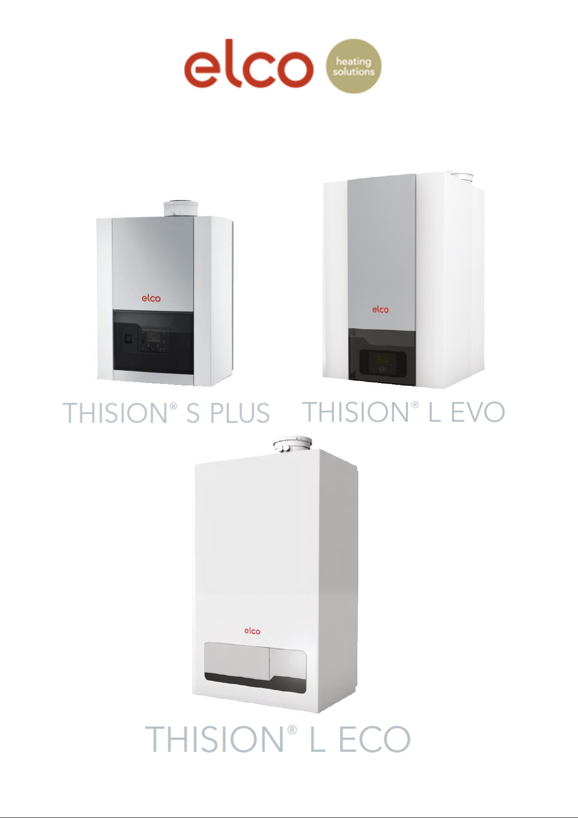
elco THISION L Evo 60, THISION L Evo 70, THISION L Eco 70, THISION L Eco 100, THISION L Evo 100 System Manual
...Page 1
Flue Gas System Guide
Flue systems for wall hung condensing boilers from 33kW to 1040kW in cascade
Page 2

Index
1. Flue Systems
1.1
1.2
1.3
1.4
1.5
Flue information and guidelines…………....
Open flue system…………………….…….…
Room sealed system…………….………….
Examples of flue gas systems……………...
Available flue systems per boiler……….……
3
3
4
5
6
2. Design and sizing information
2.1
2.2
2.3
2.4
2.5
Boiler maximum flue lengths…….……..…...
Thision S Plus………………………...
Thision L Evo……………….…………
Thision L Eco……………….……….…
Safe flue termination………………………….
IGEM-UP 10…………………………………...
BS6644 – 70kW to 1.8MW………..…………..
BS5440 – Up to 70kW………………..………
6
6
7
7
8
9
10
11
3. Flue components
3.1
3.2
3.3
3.4
3.5
3.6
Available flue components……………..……..
Thision S Plus flue components……..……….
Concentric flue……………..…..……..
Two pipe flue system……………..……
Thision L Evo flue components……….…..…
Concentric flue……….…………..……
Two pipe flue system………………..
Thision L Eco flue components………..……
Concentric flue………………..….…..
Two pipe flue system………..……….
Flexible flue components…………..….………
Cascade flue components……..……………
13
14
14
14
15
15
15
16
16
16
17
18
4. Flue component dimensions
4.1
4.2
4.3
4.4
4.5
Concentric flue parts dimensions...…………
PPs flue parts dimensions…………………….
Cascade flue dimensions………..…………..
Flexible flue dimensions…………..…………
Cascade flue dimensions…………………….
20
23
24
25
27
Page 2 of 33
Page 3

1. Flue Systems
1.1 Flue information and guidelines
Requirements and regulations
Regulations for the construction of flue gas systems are very different for each country. It should
be ensured that all national regulations with regards to flue gas systems are respected.
Pay attention to the following recommendations when dimensioning a flue gas system.
The flue gas system must be properly calculated to ensure safe operation of the system.
Flue gas system components should be removable for maintenance purposes.
Horizontal flue sections must have an incline of no less than 3° back towards the boiler.
Only materials which are heat resistant, resistant to flue gases and aggressive condensate
and also CE approved may be used.
It is the responsibility of the installer to ensure the integrity of the flue and/or chimney
system before commissioning the boiler.
Any terminal that is less than 2 metres above finished floor or ground level must be
guarded. This also applies when terminals are positioned above flat roofs and balconies to
where there is regular unimpeded access. Please see IGEM-UP10 section for more
information on termination.
Please contact Elco UK office for more information for configurations.
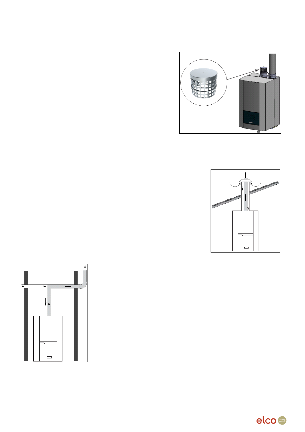
1.2 Open flue systems
Open flue systems can be designed where the combustion air supply
is taken from the room or from the surrounding area where the boiler
is installed.
The flue combustion gases are taken from the boiler and terminated
at a higher level to the air intake or a different termination location to
avoid contaminating the air supply with the flue gas. Elco recommend
that single wall plastic flue pipe (PPs) be used for open flue systems.
When designing a flue gas pipe, please ensure that the horizontal
lengths have a 3° fall towards the boiler to aid in any condensate
draining. It is not necessary to make a separate condensate drain in
the flue gas system as the condensate will be drained via the boiler
syphon.
In addition to this, we also recommend that flue brackets are used at 1 metre increments to support
the flue pipe installation. The flue pipe should also be designed to be as straight as possible to
utilise the maximum length of the flue that the boiler can run. If a bend is unavoidable, we advise
that 90° bends not be installed directly one after another.
Page 3 of 33
Page 4
Open flue systems continued…
When using an open flue system, Elco recommends that
an air inlet cover or air filter must be fitted on the air inlet
connection on the boiler, to stop any debris entering the
air supply and causing issues with the boilers
combustion. The flue system must be fitted with flue
pipes that have seamless connections only to avoid
leaks.
The maximum temperature of the flue gas for the wall
hung boiler range that we supply is 77°C so no protective
measures or clearances towards combustible objects
needs to be taken.
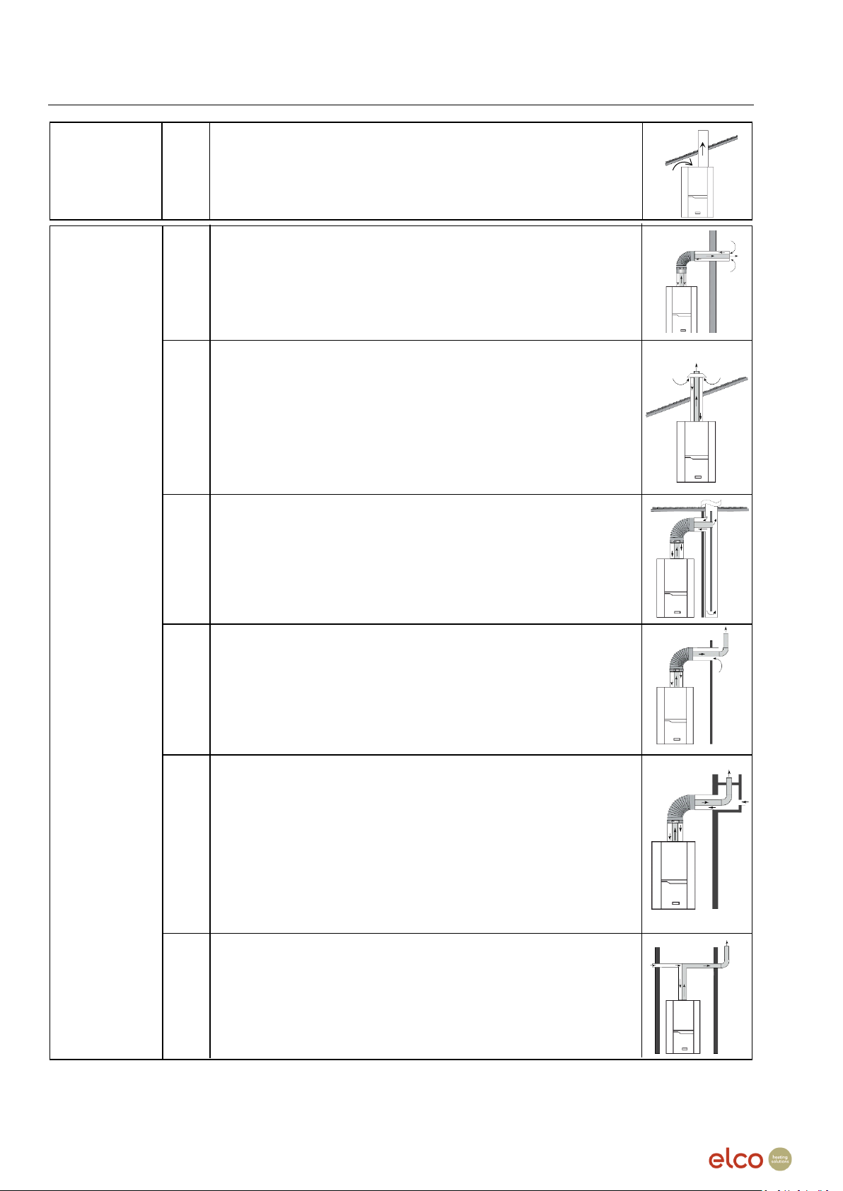
1.3 Room sealed flue systems
Room sealed flue can be constructed with either concentric flue pipe
or single pipe plastic flue (PPs). These type of systems are defined
by taking the combustion air supply from outside the room the boiler
is located.
With concentric flue pipe the combustion air is supplied and the flue
gas extracted through one concentric coaxial pipe. The combustion
air is supplied through the gap between the external painted
aluminium air pipe and the internal plastic flue pipe. Flue gases are
extracted through the internal plastic pipe (PPs).
When designing a room sealed system please ensure that the
horizontal lengths must have a 3° fall towards the boiler to aid in any
condensate draining. It is not necessary to make a separate
condensate drain in the flue gas system as the condensate will be
drained via the boiler syphon.
In addition to this, we also recommend that flue brackets be used at 1
metre increments to support the flue pipe installation. The flue pipe
should also be designed to be as straight as possible to utilise the
maximum length of the flue that the boiler can run. If a bend is
unavoidable then they must not be installed directly one after another.
The maximum temperature of the flue gas for the wall hung boiler
range that we supply is 77°C so no protective measures or
clearances towards combustible objects needs to be taken.
Page 4 of 33
Page 5
1.4 Examples of flue gas systems
B23
C13
Air/exhaust gas routing through outside wall in the same pressure
and 100 cm with a heat input from 70 up to 100 kW.
C33
C43
C53
C63
Air and exhaust connection to separate tested and supplied
building.
C83
Combustion air
Combustion air
drawn from the
room
External flue gas exhaust. Air drawn from the room.
range.
Exhaust gas/fresh air supply system through outside wall.
The Terminal outlets from separate combustion and air supply circuits
shall fit inside a square of 50 cm for boilers with a heat input to 70 kW
Flue gas exhaust and air suction duct from outside with roof terminal
in the same range of pressure.
The Terminal outlets from separate combustion and air supply circuits
shall fit inside a square of 50 cm and distance between the planes of
the two orifices shall be less than 50cm for boilers with a heat input
below 70 kW.
A square of 100 cm and distance between the planes of the two
orifices shall be less than 100 cm with a heat input above 70 kW.
drawn from
outside
Individual or shared flue gas exhaust and air suction through flue
ducting built into the building
Flue gas exhaust leading outside and air suction duct through external
wall not in the same range of pressure.
air/exhaust pipes.
Basement / floor installation.
Air and exhaust venting via exterior wall.
Exhaust venting through heat insulated exhaust pipe or moisture
resistant pipe.
Exhaust line (standing air layer) at exterior wall.
The terminals for the supply of combustion air and for the evacuation
of combustion products shall not be installed on opposite walls of the
Flue gas exhaust through individual or shared flue ducting built into
the building. Air suction through external wall.
Page 5 of 33
Page 6
1.5 Available flue systems per boiler
Concentric Flue (mm)
Plastic Single Pipe Flue (PPs) (mm)
Thision S Plus
80/125
100/150
Thision S Plus
80
100
110
125
130
34
34
46
46
54
54
Thision L Evo
80/125
100/150
Thision L Evo
80
100
110
125
130
60
60
70
70
80
80
100
100
120
120
140
140
Thision L Eco
80/125
100/150
Thision L Eco
80
100
110
125
130
70
70
100
100
120
120
Maximum length in metres for concentric room sealed installations
80/125
100/150
Changes of
direction
0 2 3 4 0 2 3
4
34
25
13.6
7.9
2.2
40
34.2
31.3
28.4
46
12 30
19.4
14.1
8.8
54
11 30
15.4
8.1
0.8
Maximum length in metres for single pipe open or room sealed installations
80mm
100mm
Changes of
direction
0 2 3 4 0 2 3
4
34
30
22
18
14
80
77.1
75.7
74.3
46
12 55
49.9
47.3
44.7
54
11 50
42.9
39.3
35.8
2. Design and sizing information
2.1 Boiler maximum flue lengths
Thision S Plus
Page 6 of 33
Page 7
2.1 Boiler maximum flue lengths continued…
Thision L Evo
80/125
100/150
(m)
(m)
60
14
38 Equivalent length in m
70
12
33
Concentric flue
Bend R = D
Bend R = D
80
7
23
gas system
90°/87°
45°/43°
100
11 80/125
1.5
1
120
7 100/150
1.5
1
Thision L Evo
80
100
110
125
130
60
17
62
70
13
52
65 Twin pipe flue
Equivalent length in m
80
7
36
47 gas system
80
100
110
125
130
100
13
23
56
88
Straight Pipe
1 1 1 1 1
120
8 13
43
65
90°/87° Bend
1.5
1.8
2
2.2
2.2
140
5
14
23
45°/43° Bend
0.8
0.9 1 1
1
Maximum length in metres for
concentric room sealed installations
100/150
Changes of direction
0 2 3
4
70
25
22
20
18
100
15
12
10
8
120
8 5 3
1
Maximum length in metres for single pipe
open or room sealed installations
100mm
Changes of direction
0 2 3
4
70
63
59
57
55
100
35
31
29
27
120
12 8 6
4
Thision L Evo
*Please be advised that we do not offer concentric flue for the Thision L Evo 140 boiler.
**Please be advised that we do not supply 130mm PPs flue.
Thision L Eco
Page 7 of 33
Page 8

2.2 Safe flue termination
In this section we aim to advise which laws and guidance are to be used in which situation. This
document will not cover every regulation but it will provide guidance as to which regulation
applies to certain situations.
The guide will look at the more common standards used to advise the requirements for flue and
ventilation installations and is not to be used as a standalone reference for regulations relating
to flue.
Please also refer to the installation and planning manuals for the specific boiler were there may
be specific information relating to flue installation standards.
When dealing with domestic installations that have a net input up to 70kW, these will be covered
by BS5440.
If the same appliance under the 70kW limit was to be installed in a commercial property then
this now needs to meet the requirements of IGE UP10 & BS6644.
However if a boiler is installed in a cascade arrangement and then exceeds the total input of
70kW then it falls under the commercial flue and ventilation requirements.
What is mandatory and what is just guidance?
British Standards (such as BS5440) are a mandatory requirement and have to be adhered
to. The approved documents offer guidance on how to comply and are only legally binding if
they are stipulated in the manufacturers installation manual. It is important to follow the
guidelines as they may be used in a court of law as the minimum expectation of a
competent person when installing a safe heating system.
The Clean Air Act is a mandatory requirement set out in Government legislation. It was
introduced in 1956 to reduce air pollution reacting to the Great Smog of London in 1952, in
that it helped the development of laws to help protect the environment.
This act targeted areas in major towns and cities, in these areas only fuels that produced
smokeless fuels could be used, also moving power stations away from main cities and
making it so that the height of certain chimneys being increased to avoid low level
contamination.
Nowadays smog is not as much of an issue as it was, but amendments of the Clean Air Act
have maintained control of emissions and the height of flue systems being more conscious
of pollution at lower levels.
Gas Safe (Gas Safety Installation and Use Regulations) is now mandatory and is there to
set out the requirements for safe installations and for working on gas installations.
IGE/IGEM is a guidance in a similar fashion to the British Standards but these are used by
industry experts as a current best practice and are in line with international and national
legislation and standards. The most relevant being IGEM UP 10 – Installation of flued gas
appliances in industrial and commercial premises.
On the following page is an extract from IGEM UP10 in relation to termination positions for
appliances over 70kW net input.
Page 8 of 33
Page 9
2.3 IGEM-UP 10
Single pipe flue minimum height of termination above a roof relating to number 1
Boiler Model
Thision L Eco Boilers
Thision L Evo Boilers
L Eco 100
L Eco 120
L Evo 80
L Evo 100
L Evo 120
L Evo 140
Above Roof
475mm
605mm
335mm
420mm
505mm
590mm
For other appliances use the calculation: Distance = 4.5675 (net heat input) - 19.723
For all sloped roofs over a 20° pitch the terminal must be 1.5 metres away.
If the flue terminates within 2.5 metres of an adjacent structure, the heights will apply to above the adjacent structure.
Elco concentric roof terminals terminates 700mm above roof level and therefore the above need not apply.
Minimum termination distances relating to numbers 2, 3 & 6
Boiler Model
Thision L Eco Boilers
Thision L Evo Boilers
L Eco 100
L Eco 120
L Evo 80
L Evo 100
L Evo 120
L Evo 140
Open Flue
1865mm
2135mm
1565mm
1740mm
1925mm
2105mm
For other open flue fan draught appliances use the calculation: Distance = 9.5156 x (net heat input) + 833.91
Room Sealed
875mm
1085mm
650mm
785mm
925mm
1060mm
For other room sealed fan draught appliances use the calculation: Distance = 7.232 x (net heat input) + 93.708
Minimum horizontal termination to opposing flat surfaces/terminals relating to number 10
Boiler Model
Thision L Eco Boilers
Thision L Evo Boilers
L Eco 100
L Eco 120
L Evo 80
L Evo 100
L Evo 120
L Evo 140
Flat Surfaces
3115mm
3775mm
2395mm
2825mm
3265mm
3705mm
For other appliances use the calculation: Distance = 23.126 x (net heat input) + 618.84
Terminals
2735mm
3285mm
2135mm
2490mm
2860mm
3225mm
For other appliances use the calculation: Distance = 19.32 x (net heat input) + 647.59
Termination positions for appliances over 70kW net input
Key to Diagram:
1 – Minimum termination height for ridged and flat roofs
2 – Minimum horizontal termination distance from openings e.g. doorways, windows, ventilation grilles, etc.
3 – Minimum horizontal termination distance from adjacent walls or obstructions
4 – Minimum distance to be 200mm for fan assisted appliances, 300mm for room sealed natural draught appliances. See BS5440.
5 – Minimum distance to be 150mm, see BS5440
6 – Minimum termination distance from openings e.g. doorways, windows, ventilation grilles, etc.
7 – Minimum distance between the flue terminals is to match the flue centres of our boilers when mounted on a cascade frame.
8 – Minimum distance below terminal or opening – 2.5 metres
9 – Minimum termination 2000mm above ground and a terminal guard must be fitted if less than 3000mmm.
10 – Opposing a terminal or flat surface.
Page 9 of 33
Page 10
2.4 BS6644 – 70kW to 1.8MW
Flue type
Ventilation direct to outside air
Ventilation to an internal space
Open flue Type B
5 cm²
10 cm²
Not permitted
Not permitted
Room sealed Type C
5 cm²
5 cm²
10 cm²
10 cm²
Open flue Type B
Ventilation direct to outside air
Low Level (Free Area / kW)
4 cm²
High Level (Free Area / kW)
2 cm²
Room sealed Type C
Ventilation direct to outside air
Low Level (Free Area / kW)
2 cm²
High Level (Free Area / kW)
2 cm²
System Type & Operational Time Grille Location
Ventilation direct to outside air
Low Level Inlet (m3/h / kW)
2.8
High Level Extract (m3/h / kW)
(Difference Between Inlet and Extract Air)
2.07 +/- 0.18
System Type & Operational Time Grille Location
Ventilation direct to outside air
Low Level Inlet (m3/h / kW)
2.6
High Level Extract (m3/h / kW)
(Difference Between Inlet and Extract Air)
1.35 +/- 0.18
Open Flued Type B and Room sealed Type C Appliances Installed within an Enclosure (Natural
ventilation requirements direct to Outside Air.)
Open Flued Appliances Installed within a Boiler Room (Natural ventilation requirements direct to
Outside Air.)
Balanced Flued Appliances Installed within a Boiler Room (Natural ventilation requirements direct to
Outside Air.)
Room sealed appliances with an Maximum Operating Pressure not exceeding 100 mbar in ventilated
occupied spaces with an air change rate exceeding 0.5 air changes per hour do not require additional
ventilation. If the air changes rate is below 0.5 per hour, 2 cm 2 kW -1 ventilation at high and at low level
shall be required.
Open Flued Appliances Installed with a Draught Diverter (Mechanical ventilation flow rate requirements
direct to Outside Air.)
Open Flued Appliances Installed without a Draught Diverter (With or without stabilizers) (Mechanical
ventilation flow rate requirements direct to Outside Air.)
Where high level discharge openings are not mechanically assisted, the free area must be calculated as
detailed above. All air inlet and extract fans must be fitted with automatic controls (interlocks) causing
safety shut-down or lockout of the installed gas burning appliances in the event of an inlet or extract air
flow failure.
Page 10 of 33
Page 11

2.5 BS5440 – Up to 70kW
Ventilation Route
Grille Location
Ventilation to room or internal space.
(The internal space ventilated into must be
ventilated as detailed above to outside air.)
Ventilation direct to outside air
Low Level (Free Area/kW)
20 cm²
10 cm²
High Level (Free
Area/kW)
10 cm²
5 cm²
Ventilation Route
Grille Location
Ventilation to room or internal space.
Ventilation direct to outside air
Low Level (Free Area/kW)
10 cm²
5 cm²
High Level (Free
Area/kW)
10 cm²
5 cm²
Air Vent Position
Appliance Input
(kW)
Fanned Draught
Distance (mm)
A
Above a
Terminal
0 to 7
300
>7 to 14
300
>14 to 32
300
>32
300
B
Below a
Terminal
0 to 7
300
>7 to 14
300
>14 to 32
300
>32
300
C
Horizontally to
a Terminal
0 to 7
300
>7 to 14
300
>14 to 32
300
>32
300
Open Flued Appliances installed within a Room (Natural ventilation requirements direct to Outside Air.)
Total rated net input not in excess of (70 kW – 7 kW) x 5cm² = Ventilation opening free area Open Flued
Open Flued appliances Installed within a compartment (Natural ventilation requirements.)
Balanced Flued Appliances Installed within an Enclosure (Natural ventilation requirements)
Page 11 of 33
Page 12

2.5 BS5440 – Up to 70kW continued…
If the chimney penetrates the dotted area,
and distance A is less than 1500mm, then
distance B shall not be less than 600mm.
Examples of the structure referred to above
include a parapet, dormer window or
chimney stack.
No part of the chimney outlet shall be less
than 1500mm measured horizontally to the
roof surface or 600mm above the ridge.
Page 12 of 33
Page 13

3. Flue Components
21
9
Available Flue Parts:
1. Wall Terminal
2. 2000mm Concentric Pipe
3. 500/1000mm Concentric Pipe
4. 90° Concentric Bend
5. 45° Concentric Bend
6. Vertical Adaptor
7. Roof Terminal
8. Flat Roof Flashing
9. Pitched Roof Flashing
10. Wall Bracket
11. Concentric Increaser
12. 2000/1000/500mm PPs Pipe
13. 90° PPs Bend
14. 45° PPs Bend
15. Plume Kit
16. PPs Increaser
17. Bird Mesh Stainless Steel Guard
18. Air Filter
19. Concentric to Parallel Adaptor
20. Air Inlet Cover
21. Parallel to Concentric Adaptor
22. PPs Reducer
*Products supplied may differ from image
1
3
2
13
12
14
15
8
16
17
18
7
11
10
6
5
4
19
20
22
3.1 Available Flue Components
Page 13 of 33
Page 14

3.2 Thision S Plus Flue Components
Concentric Flue Systems
Item
Flue Component
80/125
100/150
2
1950mm Length
3791646
3791303
3
1000mm Length
3791641
3791304
3
500mm Length
3791642
3791305
4
87°/93° Bend
3791643
3791306
5
45° Bend
3791644
3791307
1
Wall Terminal
3791645
3791308
1 + 4
Wall Terminal Kit *
FLUE-B-WALL
FLUE-B-EVOWALL
7
Roof Terminal
3791640
3791309
8
Flat Roof Slate
3791613
3791617
9
Pitched Roof Slate
3791614
3791618
10
Flue Bracket
3791612
3791616
15
Plume Kit
3791639
3791480
*Wall terminal kit includes wall terminal and 87°/93° bend
Single/Two Pipe Flue Systems
Item
Flue Component
80mm
100mm
UV Resistant 80mm
12
1950mm Length
3791584
3791297
12
1000mm Length
3791573
3791299
3791577
12
500mm Length
3791585
3791594
3791578
13
87°/93° Bend
3791574
3791300
3791579
14
45° Bend
3791575
3791301
3791580
17
Mesh Terminal
3791582
3791607
3791582
10
Flue Bracket
3791576
3791302
3791581
15
Plume Kit
3791639
3791480
3791639
Accessories
Item
Flue Component
Part Code
11
80/125 to 100/150 Concentric Increaser
3791570
16
80mm to 100mm Single Pipe Increaser
3791662
19
80/125 Concentric to Parallel Adapter
3791658
Page 14 of 33
Page 15

Elco do not supply 130mm PPs flue, if this is required then please contact a specialist flue supplier.
3.3 Thision L Evo Flue Components
Concentric Flue Systems
Item
Flue Component
80/125
100/150
110/150
2
1950mm Length
3791646
3791303
3
1000mm Length
3791641
3791304
3791621
3
500mm Length
3791642
3791305
3791622
4
87°/93° Bend
3791643
3791306
3791623
5
45° Bend
3791644
3791307
3791624
1
Wall Terminal
3791645
3791308
3791768
1 + 4
Wall Terminal Kit *
FLUE-B-WALL
FLUE-B-EVOWALL
FLU-110/150-WALL
7
Roof Terminal
3791640
3791309
3791625
8
Flat Roof Slate
3791613
3791617
3791617
9
Pitched Roof Slate
3791614
3791618
3791618
10
Flue Bracket
3791612
3791616
3791616
15
Plume Kit
3791639
3791480
*Wall terminal kit includes wall terminal and 87°/93° bend
Single/Two Pipe Flue Systems
Item
Flue Component
80mm
100mm
110mm
125mm
UV Resistant
80mm
12
1950mm Length
3791584
3791297
3791345
3791609
12
1000mm Length
3791573
3791299
3791595
3791608
3791577
12
500mm Length
3791585
3791594
3791578
13
87°/93° Bend
3791574
3791300
3791596
3791610
3791579
14
45° Bend
3791575
3791301
3791597
3791611
3791580
17
Mesh Terminal
3791582
3791607
3791607
3791619
3791582
10
Flue Bracket
3791576
3791302
3791626
3791612
3791581
15
Plume Kit
3791639
3791480
3791639
8
Flat Roof Slate
3791613
9
Pitched Roof Slate
3791614
20
Air Inlet Cover
452002280
Accessories
Item
Flue Component
Part Code
21
100/100 to 80/125 Concentric Adaptor
3791648
21
100/100 to 100/150 Concentric Adaptor
3590656
21
100/100 to 110/150 Concentric Adaptor
3791653
21
130/130 to 110/150 Concentric Adaptor
3791647
22
100mm to 80mm Reducer
3791650
16
100mm to 110mm Increaser
3590307
16
100mm to 125mm Increaser
FLUE0039AA000
22
130mm to 125mm Reducer
3590308
20
130mm Air Inlet Cover
452002300
Page 15 of 33
Page 16

3.4 Thision L Eco Flue Components
Concentric Flue System
Item
Flue Component
100/150
2
1950mm Length
3791303
3
1000mm Length
3791304
3
500mm Length
3791305
4
87°/93° Bend
3791306
5
45° Bend
3791307
1
Wall Terminal
3791308
1 + 4
*Wall Terminal Kit
FLUE-B-EVOWALL
7
Roof Terminal
3791309
8
Flat Roof Slate
3791617
9
Pitched Roof Slate
3791618
10
Flue Bracket
3791616
15
Plume Kit
3791480
*Wall terminal kit includes wall terminal and 87°/93° bend
Single/Two Pipe Flue System
Item
Flue Component
100mm
12
1950mm Length
3791297
12
1000mm Length
3791299
12
500mm Length
3791594
13
87°/93° Bend
3791300
14
45° Bend
3791301
17
Mesh Terminal
3791607
10
Flue Bracket
3791302
15
Plume Kit
3791480
18
Air Filter
3905046
20
Air Inlet Cover
452002280
Page 16 of 33
Page 17

The image on the left is an example
installation of a flexible flue solution where the
air is being taken in via the chimney cover and
then down through the chimney into the
150mm connection on the wall plate, where it
will then be taken into the boiler via concentric
flue pipe.
The flue gas is being taken from the boiler
through concentric flue pipe to the wall plate,
where it is connected to the flexible flue and
taken out through the flexible pipe to the
termination at the chimney cover.
This solution allows the boiler to operate as a
room sealed device taking combustion air from
the brick chimney which is ventilated to allow
air to be taken from outside. We recommend
that the chimney is swept prior to installation to
reduce the risk of dirt to be drawn into the
boiler.
This is mostly used in older buildings where
modification of the building is prohibited.
3.5 Flexible Flue Components
Flue Component
80mm
110mm
12.5m Flexible Flue Liner
FLUEBRECAA500
15m Flexible Flue Liner
FLUECRECAA600
25m Flexible Flue Liner
FLUEBREDAA600
FLUECREDAA600
Rigid to Flexible Adaptor
FLUEBREMAA600
FLUECREMAA700
Flexible to Flexible Adaptor
FLUEBREFAA600
FLUECREFAA600
Flexible to Rigid Adaptor
FLUEBREGAA700
FLUECREGAA700
Bracing Brackets (Pack of 5)
FLUEBREJAA500
FLUECREJAA500
Chimney Cover c/w Flex to Rigid Adaptor
FLUEBRCTAA500
FLUECRCTAA500
Chimney Support Bend
FLUEBKCRAA000
FLUECKCRAA000
Starter Kit
BRFY.AA.000
CRJEAA000
100-110 Increaser
FLUE113795
Mesh Terminal
FLUE173121
FLUE173121
Mesh Terminal
FLUE173121
Chimney Cover
FLUECRCTAA500
Bracing Brackets
FLUECREJAA500
15m Flexible Flue Liner
FLUECRECAA600
Chimney Support Bend
FLUECKCRAA00
100/150 Wall Plate
FLUECBDDAA600
100 to 110 Increaser
FLUE113795
At Elco Heating Solutions we can offer a flexible flue solution for when the flue
gas system needs to be routed through an existing chimney/void such as in listed
buildings where amendments to the building layout cannot be made.
We have a simple starter kit that has been assembled to make it easier when
selecting the required items. The starter kit includes a chimney cover, bottom
bend and support, 5 spider brackets, flexible and rigid couplings and the
installation tool.
Adding this kit to the appropriately sized flexible flue liner and the concentric/PPs
flue from the boiler, this gives you a kit that will allow you to take the flue gas to
the desired termination location as per the image.
Example of a 110mm Flexible Flue Installation
Page 17 of 33
Page 18

3.6 Cascade Flue Components
Thision L Evo
Flue Component
DN150
DN200
2 Boilers In-Line Cascade Flue
452001320
452001420
3 Boilers In-Line Cascade Flue
452001340
452001440
4 Boilers In-Line Cascade Flue
452001360
452001460
5 Boilers In-Line Cascade Flue
452001380
452001480
6 Boilers In-Line Cascade Flue
452001400
452001500
3 Boilers Back to Back Cascade Flue
452001520
452001640
4 Boilers Back to Back Cascade Flue
452001540
452001660
5 Boilers Back to Back Cascade Flue
452001560
452001680
6 Boilers Back to Back Cascade Flue
452001580
452001700
7 Boilers Back to Back Cascade Flue
452001600
452001720
8 Boilers Back to Back Cascade Flue
452001620
452001740
Thision L Eco
Flue Component
DN150
DN200
2 Boilers In-Line Cascade Flue
452004325
452004350
3 Boilers In-Line Cascade Flue
452004330
452004355
4 Boilers In-Line Cascade Flue
452004335
452004360
5 Boilers In-Line Cascade Flue
452004340
452004365
6 Boilers In-Line Cascade Flue
452004345
452004370
3 Boilers Back to Back Cascade Flue
452004375
452004405
4 Boilers Back to Back Cascade Flue
452004380
452004410
5 Boilers Back to Back Cascade Flue
452004385
452004415
6 Boilers Back to Back Cascade Flue
452004390
452004420
7 Boilers Back to Back Cascade Flue
452004395
452004425
8 Boilers Back to Back Cascade Flue
452004400
452004430
We currently do not do cascade flue for the Thision S
Plus. If you wish to install a cascade flue system for
the Thision S Plus range, please contact a specialist
flue supplier.
Elco only supply the cascade flue header as pictured,
the flue pipe exiting the cascade flue header will need
to be sourced via a flue specialist. The air intake
header will be need to be sourced by a flue specialist.
Please see the relative boiler operation and
installation manual for the information regarding
cascade flue system lengths and diameters.
Page 18 of 33
Page 19

3.4 Cascade Flue Components continued…
Thision L Evo Cascade Flue Accessories
Flue Component
Part Code
Cover for Combustion Air Inlet 100mm
For L Evo 60 – 120 Models
452002280
Cover for Combustion Air Inlet 130mm
For L Evo 140 Model
452002300
Cascade Flue System Adaptor for Thision L Evo 140
452001760
Thision L Eco Cascade Flue Accessories
Flue Component
DN150
DN200
2 Boiler In-Line Cascade Flue Fixation Rail
452004435
452004435
3 Boiler In-Line Cascade Flue Fixation Rail
452004440
452004440
4 Boiler In-Line Cascade Flue Fixation Rail
452004445
452004445
5 Boiler In-Line Cascade Flue Fixation Rail
452004450
452004450
6 Boiler In-Line Cascade Flue Fixation Rail
452004455
452004455
3 & 4 Boiler Back to Back Cascade Flue Fixation Rail
452004435
452004435
5 & 6 Boiler Back to Back Cascade Flue Fixation Rail
452004440
452004440
7 & 8 Boiler Back to Back Cascade Flue Fixation Rail
452004445
452004445
Air Filter
3905046
Cover for Combustion Air Inlet 100mm
452002280
*A cover for the air intake is supplied with the cascade flue set for the Thision L Eco
boilers
Page 19 of 33
Page 20

4. Flue Component Dimensions
Concentric Wall Terminal
1
Part
Part Code
D1
D2
D3
L1
X1
80/125
3791635
80
125
220
955
800
2
100/150
3791309
100
150
230
870
690
110/150
3791768
110
150
230
870
690
3
Concentric Roof Terminal
Part
Part Code
D1
D2
D3
D4
L1
L2
X1
80/125
3791635
80
125
140
190
1150
250
600
4
Concentric Roof Terminal
Part
Part Code
D1
D2
D3
L1
X1
100/150
3791633
100
150
175
1195
420
110/150
3791659
110
150
175
1195
420
1 2 4
3
4.1 Concentric flue parts dimensions
Page 20 of 33
Page 21

4.1 Concentric flue parts dimensions continued…
1
Concentric 90° Bend
Part
Part Code
D1
D2
L1
L2
X1
80/125
3791643
80
125
130
120
80
100/150
3791306
100
150
130
145
95
110/150
3791623
110
150
145
130
95
2
Concentric 45° Bend
Part
Part Code
D1
D2
L1
L2
X1
80/125
3791644
80
125
90
90
40
100/150
3791307
100
150
110
120
70
110/150
3791624
110
150
120
110
70
3
1000mm Concentric Straight Length
Part
Part Code
D1
D2
L1
X1 80/125
3791641
80
125
1000
950
100/150
3791304
100
150
1000
944
110/150
3791621
110
150
1000
950
500mm Concentric Straight Length
Part
Part Code
D1
D2
L1
X1
80/125
3791642
80
125
500
450
100/150
3791305
100
150
500
450
110/150
3791622
110
150
500
450
4
1950/2000mm Concentric Straight Length
Part
Part Code
D1
D2
L1
X1
80/125
3791646
80
125
1950
1890
100/150
3791297
100
150
1950
1945
4
2
1
3
Page 21 of 33
Page 22

4.1 Concentric flue parts dimensions continued…
1
80/125 to 100/150 Concentric Increaser
Part
Part Code
D1
D2
D3
D4
L1
X1
80/125
3791664
80
125
100
150
165
110
80/125 to 110/150 Concentric Increaser
Part
Part Code
D1
D2
D3
D4
L1
X1
80/125
3791659
80
125
110
150
165
115
2
100/100 to 80/125 Concentric Adaptor
Part
Part Code
D1
D2
D3
L1
L2
X1
X2
100/100
3791648
100
80
125
65
145
305
180
130/130 to 110/150 Concentric Adaptor
Part
Part Code
D1
D2
D3
L1
L2
X1
X2
130/130
3791647
130
110
150
65
145
305
180
3
100/100 to 100/150 Adaptor
Part
Part Code
D1
D2
D3
L1
L2
X1
X2
100/100
3590656
110
100
150
80
179
284
148
4
100/100 to 110/150 Adaptor
Part
Part Code
D1
D2
D3
L1
L2
X1
X2
100/100
3791653
100
110
150
52
163
320
175
1 2 3
4
Page 22 of 33
Page 23

4.2 PPS flue parts dimensions
1
2000mm PPs Straight Length
Part
Part Code
D1
L1
X1
80
3791584
80
1950
1895 100
3791593
100
1945
1890 110
3791345
110
1950
1895 125
3791609
125
2075
2000
1000mm PPs Straight Length
Part
Part Code
D1
L1
X1
80
3791573
80
100
945 100
3791299
100
995
940
110
3791595
110
1000
945 125
3791608
125
1075
1000
500mm PPs Straight Length
Part
Part Code
D1
L1
X1
80
3791585
80
500
445 100
3791594
100
495
440
1000mm UV Resistant PPs Straight Length
Part
Part Code
D1
L1
X1
80
3791577
80
100
945
500mm UV Resistant PPs Straight Length
Part
Part Code
D1
L1
X1
80
3791578
80
500
445
2
90° Bend PPs and UV Resistant PPs
Part
Part Code
D1
L1
L2
X1
80
3791574
80
130
120
75
100
3791300
100
145
130
90
110
3791596
110
120
110
60
125
3791610
125
145
150
70
3
45° Bend PPs and UV Resistant PPs
Part
Part Code
D1
L1
L2
X1
80
3791575
80
90
90
45
100
3791301
100
110
120
75
110
3791597
110
90
85
35
125
3791611
125
100
100
35
2 1 3
Page 23 of 33
Page 24

4.3 Accessory parts dimensions
1
Stainless Steel Mesh Terminal
Part
Part Code
D1
L1
X1
90mm
AT-3791582
90
125
47
120mm
AT-3791607
120
130
60
160mm
AT-3791619
160
140
60
200mm
AT-3791620
200
140
60
2
Flat Roof Flashing
Part
Part Code
D1
D2
X1
80/125
AT-3791613
135
410
100
100/150
AT-3791617
170
450
100
3
Pitched Roof Flashing
Part
Part Code
D1
L1
α (°)
80/125
AT-3791614
142
500
25° - 45°
100/150
AT-3791618
172
500
25° - 45°
4
PPs Increaser
Part
Part Code
D1
D2
L1
X1
80 to 100
3791662
80
100
165
110
80 to 110
3791651
80
110
140
85
100 to 110
3791652
100
110
160
105
5
80/125 to 80/80 PPs Adaptor
Part
Part Code
D1
D2
D3
D4
L1
L2
L3
X1
X2
80/125
3791658
80
80
80
125
175
150
255
130
120
6
Plume Kits
Part
Part Code
D1
80mm
AT-3791639
80
100mm
AT-3791480
100
4 1 2 35
6
Page 24 of 33
Page 25

4.4 Flexible flue dimensions
1
80mm Flexible Flue Liner
Part
Part Code
D1
L1
X1
12.5m
AT-3791586
80
12.5m
1490
25m
AT-3791587
80
25m
1490
110mm Flexible Flue Liner
Part
Part Code
D1
D2
X1
15m
AT-3791598
110
15m
1490
25m
AT-3791599
110
25m
1490
2
Chimney Support Bend
Part
Part Code
D1
L1
L2
L3
L4
X1
80mm
AT-3791591
80
120
130
212
390
80
110mm
AT-3791605
110
120
110
230
390
65
3
100mm to 110mm Increaser
Part
Part Code
D1
D2
L1
X1
100-110
AT-3791652
100
110
160
105
4
Flexible Flue Brackets (5 Pack)
Part
Part Code
D1
D2
L1
80mm
AT-3791589
80
40
400
110mm
AT-3791602
110
40
400
5
100mm to 110mm Increaser
Part
Part Code
D1
L1
X1
X2
110mm
AT-3791601
110
190
50
50
1
2
3 4 5
Page 25 of 33
Page 26

4.4 Flexible flue parts dimensions continued…
1
Chimney Cover for Flexible Flue
Part
Part Code
D1
D2
L1
80mm
FLUEBRCTAA500
48
246
188
110mm
FLUECRCTAA500
72
246
188
2
Flex to Flex Adaptor
Part
Part Code
D1
L1
X1
80mm
FLUEBREFAA600
80
187
87
110mm
FLUECREFAA600
110
187
87
1
2
Page 26 of 33
Page 27

4.5 Cascade flue dimensions
Thision L Eco DN150 In-Line Cascade Flue
Thision L Eco DN200 In-Line Cascade Flue
The cascade flue kits that are supplied for the Thision L Eco boilers are built from individual kits and then
multiplied dependant on how many boilers is in the installation. For example, if you have 4 boilers on an
in-line cascade frame then the kit will come with 4 sections of cascade flue and so on.
So the overall length of the cascade flue will be the individual kits multiplied by the number of boilers.
Each individual section comes with a vertical single skin pipe to be used to take the flue gas into the
cascade flue header. This section will be supplied in a 500mm length. To achieve the 3° incline back to
the boilers this length will need to be cut down to facilitate this requirement.
Page 27 of 33
Page 28

4.5 Cascade flue dimensions continued…
Thision L Eco DN150 Back to Back Cascade Flue
Page 28 of 33
Page 29

4.5 Cascade flue dimensions continued…
Thision L Eco DN200 Back to Back Cascade Flue
Page 29 of 33
Page 30

4.5 Cascade flue dimensions continued…
DN150 In-Line Cascade Flue
603mm
1493mm
205mm Centre to Centre
285mm
DN150
100mm
100mm
621mm
362mm
DN200 In-Line Cascade Flue
1493mm
205mm Centre to Centre
DN200
100mm
100mm
The cascade flue kits that are supplied for the Thision L Evo boilers is a 2 boiler version of the casade
header, however further additional extension kits and are added on depending on how many boilers is in
the installation. For example, if you have 4 boilers on an in-line cascade frame then the kit will come with
one 2 boiler in-line cascade flue set and 2 additional extension kits of cascade flue.
The overall length of the cascade flue will be the 2 boiler cascade header plus the individual extension kits
multiplied by the number of boilers.
Each extension kit comes with a vertical single skin pipe to be used to take the flue gas into the cascade
flue header. This section will be supplied in a 500mm length. To achieve the 3° incline back to the boilers
this length will need to be cut down to facilitate this requirement and this information can be found in the
cascade installation manual for the Thision L Evo boiler.
Page 30 of 33
Page 31

4.5 Cascade flue dimensions continued…
DN200 Back to Back Cascade Flue
DN150 Back to Back Cascade Flue
100mm
100mm
100mm
100mm
100mm
100mm
100mm
100mm
DN200
439mm
684mm
1422mm
149mm Centre to Centre
149mm Centre to Centre
685mm
488mm
149mm Centre to Centre
149mm Centre to Centre
1401mm
Page 31 of 33
Page 32

4.5 Cascade flue dimensions continued…
DN150 In-Line Cascade Flue Extension
100mm
DN150
689mm
DN200 In-Line Cascade Flue Extension
100mm
715mm
DN200
DN150 Back to Back Cascade Flue Extension
DN200 Back to Back Cascade Flue Extension
100mm
100mm
DN150
690mm
100mm
100mm
710mm
DN200
Page 32 of 33
Page 33

Elco Heating Solutions
3 Juniper West, Fenton Way, Southfields Business Park,
Basildon, Essex, SS15 6SJ
Tel: 01268 546700 Fax: 01268 888250
www.elco.co.uk
This publication is issued subject to alteration or withdrawal without notice. The
illustrations and specifications are not binding in detail. All offers and sales are subject
to the Company’s current terms and conditions of sale.
Page 33 of 33
 Loading...