

Page 1
Planning Document
AEROTOP T
Air-Water Heat Pump
General information
• Calculations, dimensioning, installations and commissioning
with regard to the products described in this document may only
be executed by proven experts.
• Locally valid regulations must be observed; they may deviate
from the information in this document.
• Changes remain reserved.
10/2012 Art. 420010415801
Page 2

Table of Contents
Product overview AEROTOP T............................................................................ 3
Performance curves overview AEROTOP T at 35°C flow line................................................. 4
AEROTOP T at 45°C flow line................................................. 5
Product Description AEROTOP T............................................................................ 6
Planning hints Correct dimensioning................................................................ 8
Operational limits...................................................................... 9
Determination of the heating capacity...................................... 10
Dimensioning of pressure expansion vessels........................... 11
Dimensioning AEROTOP TC integrated expansion vessel...... 12
Cooling with the heat pump system.......................................... 13
Technical Data AEROTOP T............................................................................ 16
Fan rotational speed................................................................ 22
Loss of pressure water-heat exchanger................................... 23
Integrated pumps..................................................................... 24
Remaining pump pressure....................................................... 25
Noise level................................................................................ 26
Check list For correct setup of an air-water heat pump............................ 27
Performance data AEROTOP T07 – T16.............................................................. 28
AEROTOP T20 – T35.............................................................. 29
AEROTOP T07X – T10X......................................................... 30
AEROTOP T07R – T16R (Cooling)………............................. 31
AEROTOP T20R – T35R (Cooling)………............................. 32
Setup and connection Safety, transport and installation.............................................. 33
Electrical connections, setup types.......................................... 34
Hydraulic connections, condensation water drain................... 34
Commissioning Conditions, parameterization, maintenance............................ 35
Indoor setup Unit dimensions....................................................................... 36
Air connections for indoor setup Air connections, type of setup.................................................. 38
Air inlet, corresponding unit dimensions................................... 38
Air outlet, corresponding unit dimensions................................ 39
Corner setup............................................................................ 40
Cut-out plans wall setup............................................................ 42
Accessories.............................................................................. 43
Variations corner setup with inflexible ducts............................. 47
Cut-out plans parallel setup....................................................... 49
Outdoor setup
Special regulations, setup location........................................... 51
Foundation plan....................................................................... 52
Performance diagrams AEROTOP T............................................................................ 54
Hydraulic plan Standard plans......................................................................... 74
Notes ................................................................................................. 82
Unit dimensions........................................................................ 50
2
Page 3
Product Overview
AEROTOP T
The high quality air-water heat pump
AEROTOP T extracts geothermal heat
from the environment and releases it
to the heating system at a higher
temperature. AEROTOP T heat pumps
are suitable for indoor and outdoor
installation when using the corresponding accessories (not T..C…).
The reversible model of the
AEROTOP T heat pump series can
also be used for active cooling.
The broad range of AEROTOP T heat
pumps is available in the following
versions and models:
AEROTOP T
The standard version is used
exclusively for heating, indoor or
outdoor installation, 3x400 VAC.
AEROTOP T..C
Up to model AEROTOP T12C
additionally available as compact heat
pump with integrated buffer storage,
electrical heater element, expansion
vessel and circulation pump.
AEROTOP T..X
Up to model AEROTOP T10X and to
AEROTOP T10CX also available in
1x230V (available in F / I / B).
AEROTOP T..R
Reversible heat pump in standard
version, used to heat and cool, indoor
or outdoor installation, 3x400 VAC.
AEROTOP T..RX
Up to model AEROTOP T10RX, also
available in 1x230 V (available in
F / I / B).
3
Page 4

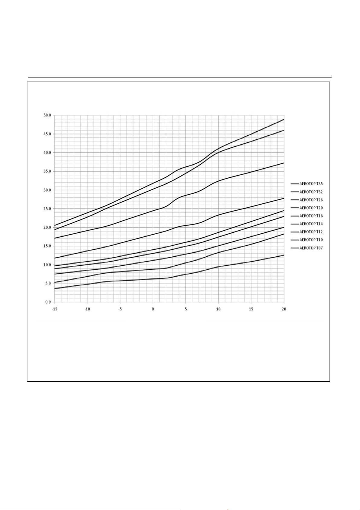
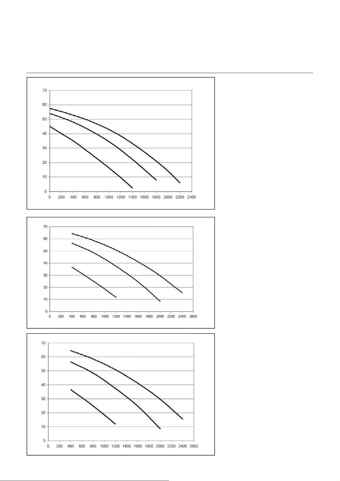
Performance Curves Overview
AEROTOP T with 35°C Flow
Heating capacity AEROTOP T with 35°C Flow
Heating capacity (kW)
Air intake temperature (°C)
Also applies to same models in compact (C), in reversible (R), and mono-phase (M) designs.
4
Page 5
Performance Curves Overview
AEROTOP T with 45°C Flow
Heating capacity AEROTOP T with 45°C Flow
Heating capacity (kW)
Air intake temperature (°C)
Also applies to same models in compact (C), in reversible (R), and mono-phase (M) designs.
5
Page 6

Product Description
AEROTOP T
High Degree of Efficiency and
Optimized Defrosting
Thanks to the correspondingly
dimensioned air heat exchanger as well
as the unique defrosting system, the
AEROTOP T heat pump is especially
efficient and a cost-saver.
This heat pump always exceeds the
required degree of efficiency
(coefficient) of3.0 (COP at A2W35).
Frost forms on the air exchanger, the
evaporator, if the exterior temperature
is less than 5°C. This results in ice
formation and as a consequence
reduces the heat exchange and with
that the efficiency of the heat pump.
The evaporator must be defrosted to
remove this frost or ice. However, the
defrosting process, carried out by the
AEROTOP T by reversing the cooling
circuit, is cumbersome since the heat
pump does not yield any energy during
the defrosting process but still uses
electricity. This is frequently
unnecessary since frost formation
depends on the humidity in the air.
Instead of the unnecessary defrosting
at timed intervals, the AEROTOP T
determines the correct time to defrost
the unit using a progressive and well
thought out logic with different performance parameters in the cooling
circuit. Thanks to this procedure, the
unit rarely requires any defrosting
during the winter, if any at all, which is
a great advantage.
Cooling with AEROTOP TR
The purpose of heat pumps is primarily
to supply a building with heat. However,
the technology can also be used to
cool a building in the summer.
This involves actively generating the
cooling energy through a process
reversal of the heat pump. In case of
distributor systems specifically
designed for cooling (fan coil or
similar), the cooling capacity of the
heat pump can be transferred optimally
to the building. Cooling ceilings also
have a good cooling capacity and
comfort level. Floor heaters, however,
are only partially suited and provide a
limited cooling effect. Radiator heaters
are unsuitable.
Cascade
Thanks to the new heat pump controller
LOGON B WP61, it is possible to link
and operate several heat generators of
a system in a cascade arrangement.
Cascades with up to 4 heat pumps, or
a bivalent operation in combination with
fossil heat generators are feasible.
When using a cascade formation, the
heat generators switch on or off
depending on the current energy
demand: If the currently running heat
pump cannot satisfy the energy
demand within a specific time, an
additional heat pump/heat generator
switches on.
Quiet Operation
Regardless whether installed indoors
or outdoors, the air-water heat pump
AEROTOP T is characterized by
comparatively very low noise
emissions. This is possible thanks to
the high-performance fan, the very
advantageous air routing, the
noise--dampening insulation of the
cladding, as well as the
multi-dampened support of the cooling
circuit. Additional noise insulation
elements are available for most
variants to reduce sound emissions
further. AEROTOP T heat pumps are
quiet and efficient. However, incorrectly
integrating constructional components
may result in undesired noise increases
if the conditions are unfavorable.
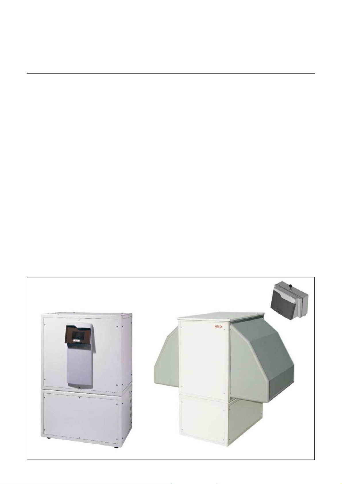
Flexible and Space-Saving
Thanks to the clever utilization of the
geometric properties of the radial fan,
AEROTOP T heat pumps are among
the most flexible, space saving
air--water heat pumps. Especially
noteworthy is the fact that the heat
pump can be placed into the left or right
corner of the utility room when not
using the air ducts. The exhaust
opening is easily moved on-site from
the left to the right and even to the top
without having to use any additional
tools. The intake openi
selected as desired without special
accessories. AEROTOP T heat pumps
are also suitable for outdoors
installation when using the
corresponding accessories.
ng can also be
6
Page 7

Product Description
AEROTOP T
Enclosure and Special Components
The enclosure consists of a frame that
is completely free of thermal bridging,
sound dampened, and specifically
developed for use with heat pumps.
The cladding and panels feature a
high-grade insulation to sound-dampen
and thermally insulate the unit.
A pedestal or base is not required since
the feet of the unit feature a vibrationdampening design. All panels can
be detached for easy access to the
internal elements of the unit and for
control or configuration tasks.
The high-performance radial fan
ensures the unit runs efficiently and
quietly. The high performance cooling
circuit is mounted on a vibrationdampened support and features a
thermostatic expansion valve, filter
dryer, inspection glass, high-pressure
pressure controller with manual reset,
and a low-pressure pressure controller
with automatic reset function. The
hermetic scroll compressor is mounted
on a double vibration dampened s
upport. The evaporator consists of a
large-area finned tube heat exchanger
made from aluminum and copper; the
condenser consists of a welded
chromium steel high performance plate
heat exchanger. The environmentally
friendly refrigerant R407C is used as
the working medium. A flow monitor on
the consumer side ensures trouble-free
cooling for reversible heat pumps.
Brief Description of the LOGON B
WP61 Controller
Plain text display unit, control and
protection of the cooling circuit, defrost
logic, malfunction display and diagnostics, control of a sliding or mixed
heating circuit, service water heating,
storage tank charging, control of the
electrical auxiliary heater, expandable
for several mixed heating circuits.
LPB system bus with up to 15 heating
circuits per segment, bivalent operation
with additional heat generator (oil/gas),
cascade of several HPs. cooling
function, improved solar function
(heating support, pool, PWH), pool
function, controlling the multi-phase
electrical heating elements.
Selectable Connections
The connections for heater flow and
return, condensate drain, and electrical
connections can be placed on the left
or right side during the on-site
installation and even directed towards
the bottom when installed outdoors.
7
Page 8
Planning Notes
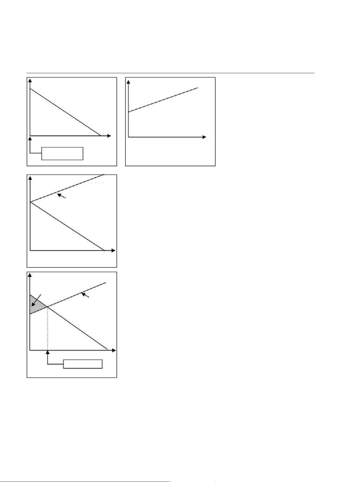
Correct Dimensioning of the heating capacity
Heat demand of the building
Heating capacity of
an air-water heat
Exterior temperature
Exterior design
temperature
Exterior temperature
Heat Demand and Heat Capacity
The correct dimensioning of the
air-water pump is a key task. The heat
pump must meet the heat demand of
the building. This demand increases as
the exterior temperature drops but the
heat capacity of the air-water heat
pump decreases at the same time. The
two charts illustrate this opposing trend.
Heating capacity
Heat demand
of the building
Exterior temperature
Chart A
Heating capacity
Heat output
Auxiliary heater
Heating capacity of
an air-water heat
pump dimensioned
for exterior design
temperature (output
Heating capacity of
an air-water heat
pump dimensioned
for bivalence
temperature
(correct output)
Exterior temperature
too high)
Correct Dimensioning and
Bivalence Point
This makes it clear that a monovalent
system with an air-water heat pump as
the only heat generator has a clearly
overdimensioned heat pump during
most of the year and especially during
the intermediate season. Not only does
this result in higher investments costs,
the more frequent switching (on, off) of
the heat pump also has a negative
effect on the pump's efficiency and
thereby increases operating costs
(see chart A).
A somewhat smaller heat pump is
selected for a bivalent system. This
pump is dimensioned not for the
exterior design temperature of the
system but a slightly higher exterior
temperature instead, the so-called
bivalence point. If the exterior temperature drops below the bivalence point,
an electrical auxiliary heater is
switched on, this then covers the
missing heat output. The heat pump
continues to have priority and, together
with the additionally activated
electrical heater, delivers the required
heat (see chart B).
With a bivalence point, the heat pump
is dimensioned exactly to meet the heat
demand of the building. With lower
exterior temperatures, the electrical
auxiliary heater is activated; with higher
exterior temperatures, the heat pump is
still overdimensioned but to a lesser
degree. An optimal annual degree of
efficiency (coefficient) is achieved if the
bivalence point is set to be slightly
below the temperature most frequently
occurring at the building location.
Bivalence point
Chart B
8
Page 9
Planning Notes
Operating Limits
General Information
The rated throughput values for
evaporator and condenser are
minimum values. Set points and
adjusted parameters may not fall below
these values to ensure the indicated
performance.
Pipes, tubes, and air ducts must be
kept as short as possible and routed in
such a way that pressure and heat loss
are minimized. Incorrectly or badly
installed or dimensioned pipes, tubes,
or air ducts may damage the heat
pump.
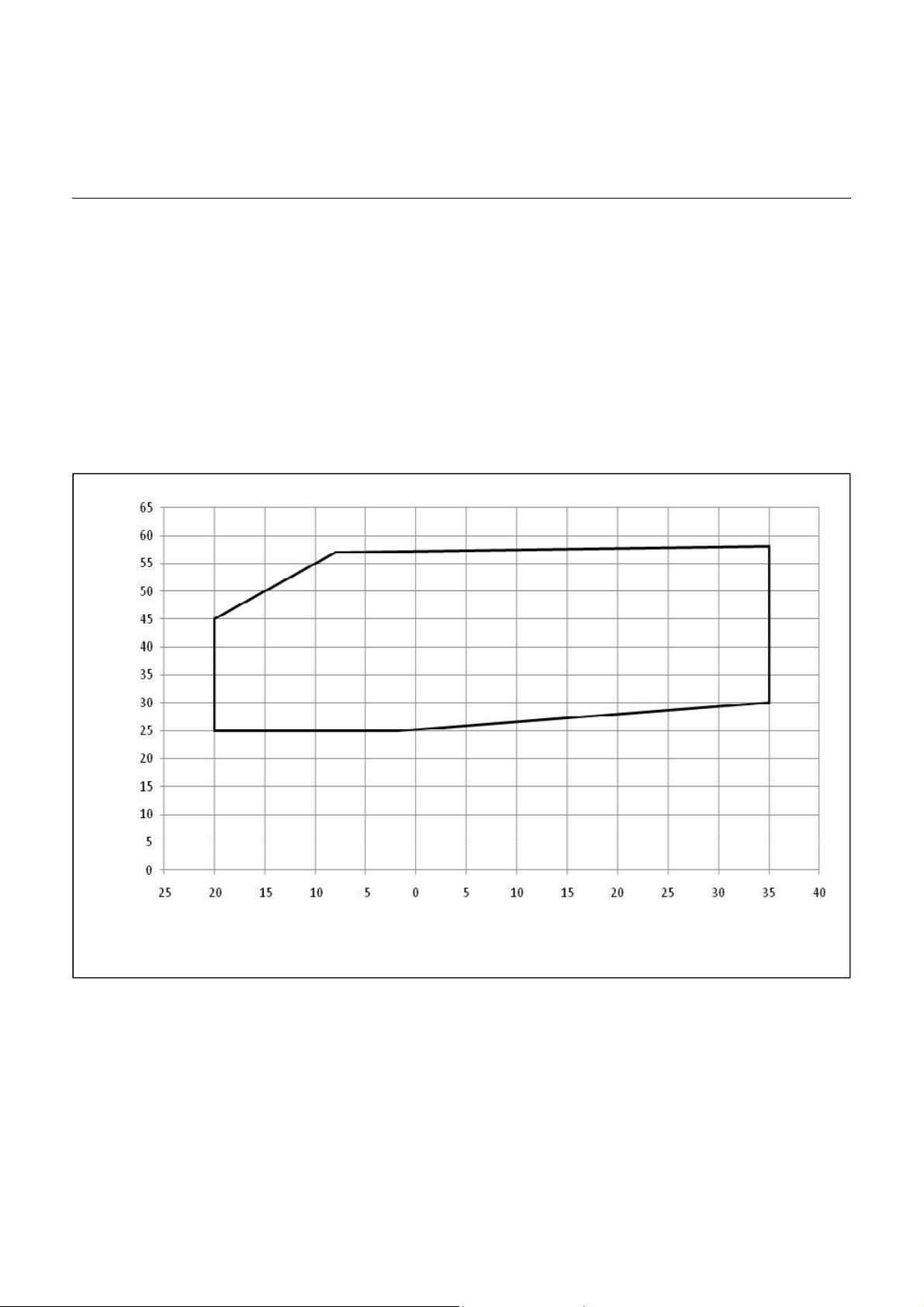
Area of Application
The following chart depicts the
application area of the air-water heat
pump AEROTOP T. Please consult the
performance overview for more
detailed operating specifications for
various heat pump models. The
temperature difference at the
condenser must be between
7 and 10°C.
flow temperature [°C]
Operating the heat pump is prohibited
if the following conditions exist:
• Construction drying
• System/unit used in unfinished
buildings
• Windows or exterior doors
unfinished and locked
These cases require the use of a
specific construction heating system.
Functional heating or surface-ready
heating with the heat pump acc. to
DIN EN 1264 is only permitted when
complying with these conditions.
source inlet temperature [°C]
Furthermore, it must be noted that the
design of the heat pump concerning its
standard operation may not yield the
full extent of the required heat output.
The following notes must be observed
as well:
• Comply with the corresponding
standards and rules of the
floor/screed manufacturer!
• Proper function is only ensured
with a correctly installed system
(hydraulics, electrical, settings)!
• Deviations may damage the
floor/screed!
9
Page 10
Planning Notes
Determining Heat Output and Allowances
Retrofitting an existing oil or gas
heater with heat pump:
The heating capacity can be calculated
based on the existing average fuel
consumption.
Gas heater
Oil heater
Mid-level
altitude
In excess of
800 m above
With hot water
Qh = Oil consumption (Ltr.)
Qh = Oil consumption (Ltr.)
Mid-level altitude Qh = Gas consumption (m3) x 0.93
300
In excess of
800 m above
Qh = Gas consumption (m
330
3
) x 0.93
Qh = Heat demand in kW
Hot water demand
Hot Water Allowances
The allowance for generating hot water
per person
and day (l)
can be taken into account as follows:
Example
Number of people 4
Hot water demand 50 liters
per person and day.
Heat demand allowance:
Q˙WW = 4 x 0,085 kW = 0,34 kW
With hot water
Without hot water
Qh = Oil consumption (Ltr.)
300
265
Qh = Oil consumption (Ltr.)
330
Without hot water
295
Qh = Gas consumption (m3) x 0.93
265
Qh = Gas consumption (m3) x 0.93
295
Additional heating output
per person (kW)
Tw = 45°C
∆T = 35 K
30 0,051
40 0,068
50 0,085
60 0,102
Allowances to the Heat Pump Output
Off Periods
Blocked Times
The off periods (blocked times)
theoretically should be considered by
f = 24 h
24 h - off period per day (h)
the following formula and the heat
demand should be multiplied with the
factor f.
10
Page 11

Planning Notes
Configuration of Pressure Expansion Vessels
VN = VA x F x X
Key
Vn = Expansion volume
VA = System content acc. to
list below
F = Temperature-dependent
Factor
TZ = Average system temperature TZ = (TV + TR)/2
= F
X = Safety factor
Safety factor for boiler output
Important
Water contents of hot water tanks
(buffer storage) are not considered in
the table and must be added
separately.
40°C 50°C 60°C 80°C
0,0079 0,0121 0,0171 0,029
Up to 30 kW X = 3,0
31 - 150 kW X = 2,0
above 150 kW X = 1,5
1 = Floor heating
2 = Radiators
3 = Heating panels
Select the expansion vessel based on
the expansion volume and the system
height Hp. The system height Hp is the
height from the middle of the expansion
vessel up to the upper point of the
heating unit.
VA system capacity (liter)
Boiler output (kW)
Type
PND 18 10,3 8,7 7,7 6,6 5,1 3,5
PND 25 14,3 12,0 10,7 9,1 7,1 4,7
PND 35 20,2 17,0 15,0 13,0 10,0 7,0
PND 50 28,6 24,4 21,4 18,5 14,3 9,8
PND 80 45,7 38,6 34,3 29,7 22,9 16,5
max. height Hp 2 m 5 m 7 m 9 m 12 m 15 m
11
0,5 bar 0,8 bar 1,0 bar 1,2 bar 1,5 bar 1,8 bar
Initial Pressure in Empty Vessel (= Hp + 0,3 bar)
Page 12
Planning Notes
Configuration of the AEROTOP TC integrated 12 litre
expansion vessel
General information for the correct
configuration
The heat pumps AEROTOP T..C can
be installed without an additional
external expansion vessel if all of the
following conditions are met:
• Direct heating circuit: Standard 1
or standard 1-6
• H (height of system) <= 7m
• Heating capacity at outdoor
temperature (Ta) –10°C of
maximum 10kW. (Note:
AEROTOP T12C electric heater
element with max. 2 kW)
• Water volume of the system VA
must not exceed the values given
in the table.
Installation example
AEROTOP T12C, electric heater
element with maximum capacity of
2 kW, standard
• TZ 35°C: Maximum averaged
temperature of the system during
heating mode (corresponds to
40°C/30°C)
• H (system height) <= 7m
• Ta (dimensioning of outdoor
temperature): -10°C
• AEROTOP T12Cmaximum capacity
at Ta of -10°C and 40°C
Flow temperature: 7.4 kW + 2 kW
Electric heater element = 9.4 kW
< 10 kW, OK!
• Requirement: VA <= 290 litres;
rough verification: Maximum
heating capacity at Ta of 9.4 kW x
20 litres/kW for underfloor
heating + 50 litres Integrated
accumulation tank = 238 litres
< 290 litres: OK!
VA must be known for final
dimensioning of the expansion
vessel.
Permissible water volume VA of the
system
The following table gives the maximum
water volumes for the system
depending on the TZ (max. averaged
temperature of the system during
heating mode) and the structural height
of the system (H), whose expansions
can be absorbed by the integrated
12 litre expansion vessel.
H (m) p
2 0.5 550 390 300 230 190 160 130
3 0.6 520 370 280 220 180 150 130
5 0.8 460 330 250 190 160 130 110
6 0.9 430 310 230 180 150 120 100
7 1 400 290 210 170 140 110 100
9 1.2 340 250 180 140 110 100 -
12 1.5 240 180 130 - - - -
15 1.8 - - - - - - -
H System height
p
(bar) Minimum primary pressure of expansion vessel
o
TZ Maximum averaged operating temperature of the system (Tvl + Trl)/2 during heating mode
PSV Switching-on point of the pressure relief valve = 3 bar
Permissible water volume of the system. Heating system water volume including 40 litres of the
V
A
integrated accumulation tank
(bar) TZ = 30°C TZ = 35°C TZ = 40°C TZ = 45°C TZ = 50°C TZ = 55°C TZ = 60°C
0
VA [Litres]
12
Page 13

Planning Notes
Cooling with Heat Pump Systems
Active Cooling
The cooling energy is produced actively
using the heat pump to cool. The
purpose of heat pumps is primarily to
supply a building with heat. However,
the technology can also be used to
cool a building in the summer.
This requires a process reversal during
the cooling cycle. In this case, the heat
emission side (condenser) becomes
the heat absorption side (evaporator).
During this phase, the heat pump
functions like a refrigerator.
The cooling and heating cycle cannot
run at the same time. The use of a cool
store is recommended in any case
to prevent the heat pump from
switching on and off and switching to
water heating too often. Depending
on the system concept, the heating
storage can also be used as cooling
storage. In case of distributor systems
specifically designed for cooling (fan
coil orsimilar), the cooling capacity of
the heat pump can be transferred
optimally to the building. Cooling
ceilings also have a good cooling
capacity and comfort level. Floor
heaters, however, are only partially
suited and provide a limited cooling
effect. Radiator heaters are unsuitable.
Active Cooling Insulation
Water at a temperature less than 17°C
is considered to be cold water. In the
presence of cold water, the usual
heating system insulations cannot be
used. Suitable insulation, especially
when using active cooling, is
necessary. Insulation suitable for cold
water is primarily used to avoid
condensation but also to prevent cold
water absorbing any of the heat, and
also to protect against external
mechanical stresses. Condensation
must be avoided with a suitable
insulation to prevent surface corrosions
on the distributor system or mold in
moist layers.
Insulation for cold water must be
vapor-- proof and installed to all
distributor system elements (pipes,
tanks, pumps, cocks, valves, etc.) in a
vapor-proof manner. Special insulating
materials are commercially available in
different designs (e.g. Armaflex,
Tubolit). Standards SIA 380, DIN 4140
describe the insulation techniques.
Please comply with the guidelines of
relevant local professional associations
(VSI, VDI, FESI).
General Cooling Information
1. The cooling cycle always must be
monitored. If the room air is cooled
unchecked, condensation water will
emerge.
This may damage the equipment
or building components. The flow
temperature in conjunction with the
humidity (dew point contact
temperature detector or room
sensor for humidity and tempera
ture) is best for monitoring.
2. A separate cooling circuit should
be planned for the cooling mode.
This circuit can be combined with a
cooling ceiling or ventilation system,
for example. Partial cooling via the
floor heater or convectors is also
possible if the need for cooling is
limited.
3. Water flow must be ensured or
cooling is not possible. When
cooling via the heating surfaces,
thermostatic individual controls
must be used that can be switched
to cooling mode. The valves are
otherwise closed in summer and
cooling is impossible.
Measures to Reduce the Building
Cooling Capacity
The room cooling capacity is calculated
based on the sum of the individual room
demand. If the cooling demand exceeds
the available cooling capacity, the
following reduction measures may be
used:
1. Direct sunlight through the window
areas can be restricted through
constructional measures (shutters,
window shades, blinds).
2. The amount of sunlight received by
each room frequently differs due to
the different cardinal points.
is means that not the entire
Th
cooling capacity must be available
at the same time. This can reduce
the max. simultaneous cooling
demand.
3. Nighttime cooling of constructional
elements can also lower the
daytime cooling demand.
Calculating the Cooling Capacity
The cooling demand is calculated in
accordance with national and local
standards.
E.G.:
VDI 2078 : Real estate and buildings
DIN 18599: Energetic assessment of
nonresidential buildings (also includes
air-conditioning or cooling)
DIN EN ISO 13790 Energetic
assessment of buildings (similar to
DIN 18599) only across Europe
DIN EN 255
SIA382/2: Room temperature
requirements.
SIA382/3: Determining the cooling
requirement of building.
Cooling is differentiated by internal
cooling capacity (e.g. thermal discharge
of equipment, persons, lights) and
external cooling capacity (sun exposure,
heat from building components, and
ventilation gains due to exterior air).
The estimate acc. to HEA can be used
for approximate calculations. However,
the conditions listed below must
be taken into account as well. The
calculations of the implementation
phase must be based on national
and local standards.
Empirical Data for a Quick
Calculation
Factors
Private residences 30 Watt/m3
Offices 40 Watt/m3
3
Sales rooms 50 Watt/m
Glass additions 200 Watt/m
3
13
Page 14
Planning Notes
Cooling with Heat Pump Systems
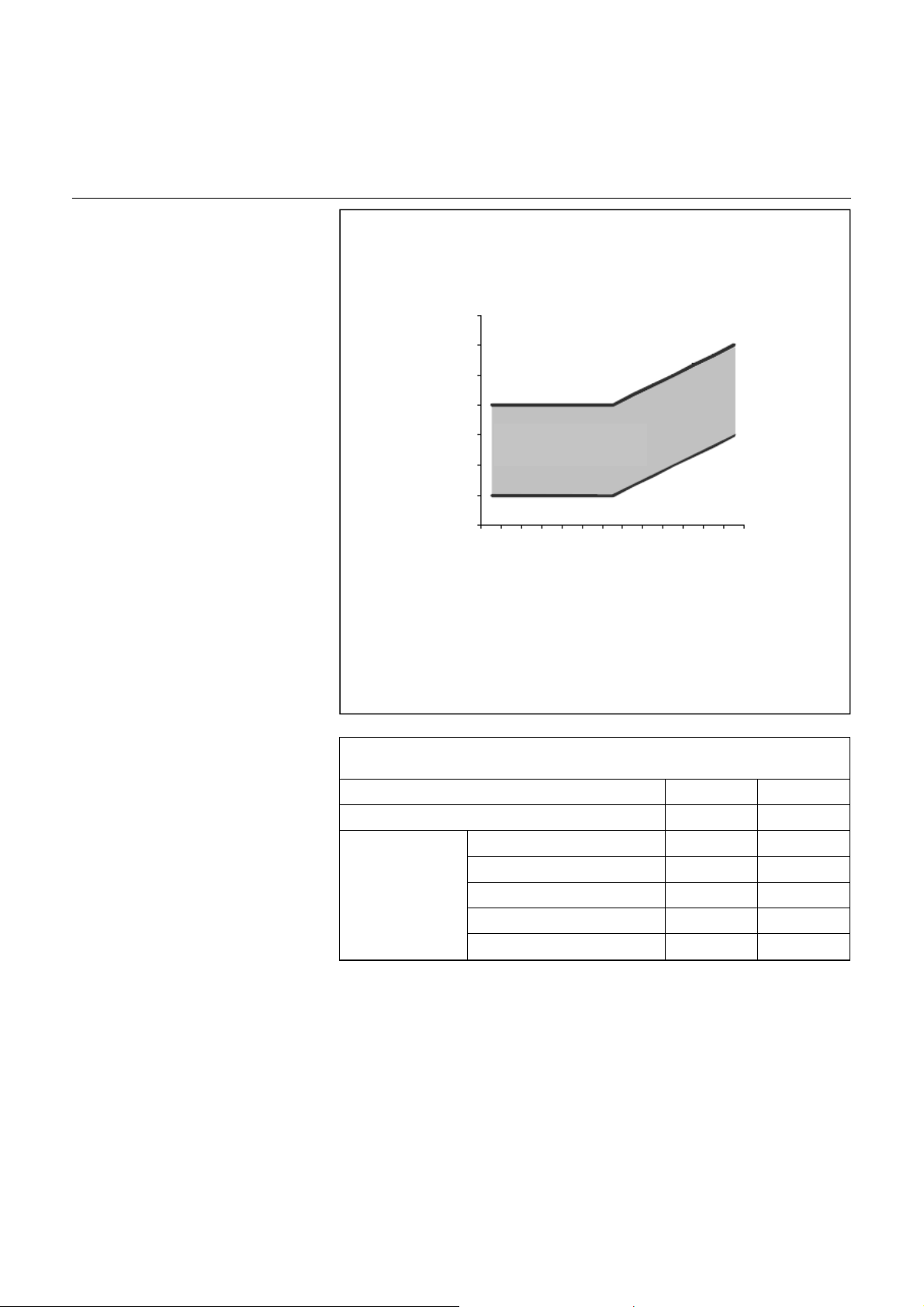
Comfortable Room Temperature
A room is considered to be thermally
comfortable when the room temperature in the summer is below 28°C.
This does not apply to air-conditioned
rooms. Other factors are affecting
thermal comfort ranges as well.
Thermal comfort requirements are
defined in standard DIN EN 15251,
which provides a general guideline
when implementing construction
projects.
Recommendations for Surface
Temperatures of Cooled Floors
When using a floor area for cooling, the
comfort requirements and the weather
data can be used to estimate the
condensation risk so that the surface
temperatures should generally be in a
range of 20°C to 29°C.
Special attention must be paid to floor
surfaces that are used when barefoot,
for example, in bathrooms, since the
surface temperatures perceived as
being comfortable may be significantly
higher depending on the floor covering.
Rooms with high humidity loads,
especially bathrooms and kitchens,
should not be cooled or only by
considering the dew point threshold.
28
27
26
25
24
23
Room temperature in °C
22
21
Range of comfortable
Temperature
20 21 22 23 24 25 26 27 28 29 30 31 32
Outside temperature in °C
Comfortable floor surface temperatures
min max
Wearing shoes 19 °C 29°C
Carpet 21°C 28°C
Pine wood 23°C 28°C
Barefoot
Oak 24°C 28°C
Linoleum 24°C 28°C
Concrete/screed 26°C 28°C
14
Page 15
Planning Notes
Cooling with Heat Pump Systems
Monitoring Function to Prevent
Condensate Precipitation
To avoid condensation, the integrated
Logon B WP61 controller features
different monitor functions.
1. Flow Temperature Monitor
The temperature is set at the factory to
18°C. This temperature value ensures
in almost all cases that condensation
does not occur. A dew point monitor
should always be used in addition.
2. Dew Point Monitor
This device is attached to critical points
such as the floor heating distribution
box. As soon as the connected dew
point monitor detects condensation, it
closes the contact and thereby
switches cooling off.
3. Hygrostat
To prevent condensate due to a room
humidity that is too high, a hygrostat
can be connected, which then realizes
a fixed flow temperature increase.
As soon as the value set at the
hygrostat is exceeded, the hygrostat
closes the contact and this triggers the
flow temperature set point increase
set here.
High-End Solutions
4. Humidistat
To prevent condensate due to a room
humidity that is too high, a humidistat
can be connected, which then realizes
a continuous flow set point increase.
If the relative room humidity exceeds
an adjustable value, the flow set point
is increased steadily.
5. Room Sensor for Humidity and
Temperature
The dew point temperature is
determined based on the relative room
humidity and the associated room air
temperature.
To prevent water condensation on
surfaces, the flow temperature is min.
limited by an adjustable value that is
above the dew point temperature.
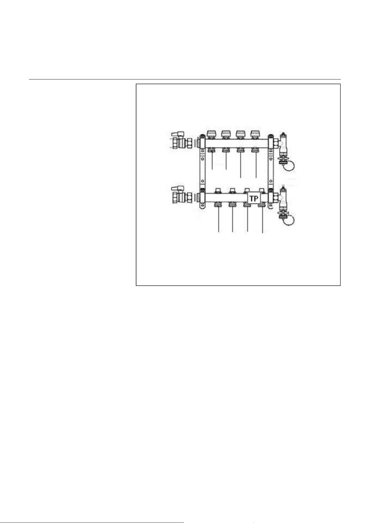
Distributor Box
Return Flow
Flow
TP = Dew point temp. Monitor
Dehumidifier
An external dehumidification can be
used in combination with the last two
monitoring functions. An external
de-humidifier can be switched on to
reduce the humidity in the air.
15
Page 16
Technical Data
AEROTOP T07(C)-T16
Heat pump type AEROTOP T T07(C) T10(C) T12(C) T14 T16
Heating operation For A2/W35
Heating Capacity Qh kW
Power input Pel kW
Performance number EN14511 COP Heating operation For A7/W35
Heating Capacity Qh kW
Power input Pel kW
Performance number EN14511 COP Condenser Scroll hermetically
Maximum current consumption lmax. A 6.3 10 11 13 13.5
Start-up current with smooth starter VSA A 15.75 25 27.5 32.5 33.75
Current intensity with blocked rotor LRA A 40 50 66 74 74
Current connection V-f-Hz 400-3-50
Fuse WP A/T 16 16 16 20 20
Fuse WP with electrical insert A/T 20 20 20 25 25
Condenser, heater side Material: Chrome steel AISI 304, 1.4301
Hydraulic connections IG Zoll 1” 1” 1” 1” 1”
Water content incl. connection hoses AEROTOP TC l 53 53 53 - Water content incl. connection hoses AEROTOP T l 2.6 3 3.1 3.4 3.4
Volume stream heating operation nom/min
Pressure loss heating operation
AEROTOP TC kPa 8.4/2.1 16.4/4.1 22.8/5.7
AEROTOP T kPa 28.3/4.4 32.9/4.1 33/4.5 36.5/4.6 35.5/5.5
Residual pressure AEROTOP TC
Expansion tank heating AEROTOP TC V l 12 12 12 - Primary pressure heating-circuit expansion tank p bar 1 1 1 - Maximum working pressure p bar 3 3 3 3 3
Evaporator/fan
Volume stream m
Available pressure
Power consumption fan
Maximum current consumption fan lmax. A 1.6 1.6 1.6 2.1 2.1
Coolant R407C
Coolant filling AEROTOP TC kg 1.9 2.95 3.7 - Coolant filling AEROTOP T kg
Coolant circuit oil - Ester oil
Oil quantity l 1.1 1.36 1.85 1.65 1.89
Weight heat pump
AEROTOP TC kg 239 274 299 - AEROTOP T kg 204 246 272 276 279
Indoor setup
Sound power level
On exhaust
Inside Lwa dB(A)
Outdoor setup
Sound power level standard configuratuion Lwa dB(A)
Sound pressure level standard configuratuion in 1 m Lpa dB(A) 51.0 54.0 50.0 55.0 59.0
LP pressure control OFF-switch off p bar 0.2
LP pressure control ON- switch on p bar 1.6
HP pressure control OFF-switch off p bar 29.0
HP pressure control ON- switch on p bar 24.0
1) Min: ∆t max= 10 K, with PHW-preparation ∆tmax = 5 K. (V' [l/h]= Qh[kW]/(4.18*∆t[K]*ρ[kg/l])*3600)
2) Residual pumping pressure is stated for maximum pumping stage.
3) At maximum fan rotational speed.
4) At fan rotational speed setting B (T07(C), T10(C), T12(C), T14, T16).
5) Data for star/V connection of the electric motor. The machines are factory-equipped with star connection.
6) Measuring according to DIN ISO 9614-2. Sound power level is a property of the source of noise and therefore dependent on the
distance; it describes the totality of the sound power of the corresponding source radiating in all directions. Information to determine
the noise level see planning documents.
7) Information without consideration of a light well or air duct, which reduce the noise level considerably. Screen noise absorbers
reduce noise by 6-7 dB(A).
3)
Pa
4)
P kW
6)
On suction 7) Lwa dB(A)
2)
7)
Lwa dB(A)
1)
l/h
kPa 51.4 57.9 55.4
3
/h
16
6.4 9.1 11.8 13.7 14.8
2.0 2.8 3.4 3.9 4.1
3.3 3.3 3.5 3.5 3.6
8.1 11.5 13.6 15.8 17
2.0 2.9 3.4 3.9 4.2
4.0 4.0 4.0 4.0 4.1
1500/568 2100/835 2700/999 3070/1171 3100/1300
2'500 3‘300 5'300
150 92 146
0.035 0.100 0.100
2.5 3.1 3.7 4.1 4.1
53.0 56.0 54.0 59.0 61.0
48.0 53.0 50.0 53.0 55.0
50.0 54.0 55.0 60.0 60.0
62.0 65.0 61.0 66.0 70.0
6'300 6'800
112 82
0.170 0.210
Page 17
Technical Data
AEROTOP T20-T35
Heat pump type AEROTOP T T20 T26 T32 T35
Heating operation For A2/W35
Heating Capacity Qh kW
Power input Pel kW
Performance number EN255 COP Heating operation
Heating Capacity Qh kW
Power input Pel kW
Performance number EN255 COP Condenser Scroll hermetically
Maximum current consumption lmax A
Start-up current with smooth starter VSA A
Current intensity with blocked rotor LRA A
Current connection V-f-Hz
Fuse WP A/T
Condenser, heater side Material: Chrome steel AISI 316, 1.4401
Hydraulic connections IG Zoll
Water content incl. connection hoses AEROTOP T l
Volume stream heating operation nom/min
Pressure loss heating operation kPa
Maximum working pressure p bar
Evaporator/fan
Volume stream m
Available pressure
Power consumption fan
Maximum current consumption fan lmax. A
Coolant Coolant filling AEROTOP T kg
Coolant circuit oil - Ester oil
Oil quantity l
Weight heat pump
AEROTOP T kg
Indoor setup
Sound power level
On exhaust
Inside
Outdoor setup
Sound power level with
Sound pressure level with hoods in 1 m
LP pressure control OFF-switch off p bar
LP pressure control ON- switch on p bar
HP pressure control OFF-switch off p bar
HP pressure control ON- switch on p bar
3)
Pa
4)
P kW
6)
On suction 7)
6)
hoods
7)
1)
7)
l/h
3
/h
Lwa dB(A)
Lwa dB(A)
Lwa dB(A)
Lwa dB(A)
Lpa dB(A) 55.0 59.0 56.0 59.0
18.9 24.4 30.2 33.4
5.8 7.4 8.8 9.2
3.2 3.3 3.4 3.6
for A7/W35
22.4 30.8 37.9 39.6
6.0 7.6 8.9 9.6
3.7 4.1 4.3 4.1
16 22 27 25
40 55 67.5 62.5
99 123 127 167
400-3-50
25 32 40 40
1¼” 1¼” 1¼” 1¼”
4.9 4.9 5.7 5.7
3700/1714 5850/2259 6280/2803 7300/2964
14.9/4.5 32.9/7.7 36.1/6.4 46.7/7
10 10 10 10
7'300 8'300 10'000
155 75 255
0.530 0.700 0.500
1.8 1.8 2.8 2.8
R407C
6 7.4 9.2 9.2
4.1 4.1 4.1 4.1
375 392 460 468
65.0 67.0 66.0 70.0
59.0 61.0 64.0 67.0
59.0 59.0 63.0 68.0
66.0 70.0 67.0 70.0
0.2
1.6
29.0
24.0
11'000
180
0.650
1) Min: ∆t max= 10 K, with PHW-preparation ∆tmax = 5 K. (V' [l/h]= Qh[kW]/(4.18*∆t[K]*ρ[kg/l])*3600)
2) Residual pumping pressure is stated for maximum pumping stage.
3) At maximum fan rotational speed.
4) At fan rotational speed setting B (T07(C), T10(C), T12(C), T14, T16).
5) Data for star/delta connection of the electric motor. The machines are factory-equipped with star connection.
6) Measuring according to DIN ISO 9614-2. Sound power level is a property of the source of noise and therefore dependent on the
distance; it describes the totality of the sound power of the corresponding source radiating in all directions. Information to determine
the noise level see planning documents.
7) Information without consideration of a light well or air duct, which reduce the noise level considerably. Screen noise absorbers
reduce noise by 6-7 dB(A).
17
Page 18
Technical Data
AEROTOP T07(C)X-T10(C)X (available in F /I / B)
Heat pump type AEROTOP T..X T07X (C) T10X (C)
Heating operation For A2/W35
Heating Capacity Qh kW
Power input Pel kW
Performance number EN255 COP Heating operation for A7/W35
Heating Capacity Qh kW
Power input Pel kW
Performance number EN255 COP Condenser Scroll hermetically
Maximum current consumption A 17.3 23.5
Start-up current with smooth starter A 40 40
Current intensity with blocked rotor LRA 76 114
Current connection V-f-Hz 230-1-50
Fuse WP A/T 25 32
Fuse WP with electrical insert: 2 kW A/T 32 40
Fuse WP with electrical insert: 4 kW A/T 40 50
Fuse WP with electrical insert: 6 kW A/T 50 63
Condenser, heater side Material: Chrome steel AISI 304, 1.4301
Hydraulic connections IG Zoll
Water content incl. connection hoses AEROTOP TC l
Water content incl. connection hoses AEROTOP T l
Minimum volume stream heating operation
Pressure loss heating operation
AEROTOP TC kPa 8.4/2.1 16.4/4.1
AEROTOP T kPa 28.3/4.4 32.9/4.1
Residual pressure AEROTOP TC
Expansion tank heating AEROTOP TC V l
Primary pressure heating-circuit expansion tank p bar
Maximum working pressure p bar
Evaporator/fan
Volume stream m
Available pressure
Power consumption fan
Maximum current consumption fan A
Coolant Coolant filling AEROTOP TCX kg
Coolant filling AEROTOP TX kg
Coolant circuit oil - Ester oil
Oil quantity l 1.1 1.36
Weight heat pump
AEROTOP TC kg 242 278
AEROTOP T kg 207 250
Indoor setup
Sound power level
On exhaust
Inside Lwa dB(A)
Outdoor setup
Sound power level standard configuratuion Lwa dB(A)
Sound pressure level standard configuratuion in 1 m
LP pressure control OFF-switch off p bar 0.2
LP pressure control ON- switch on p bar 1.6
HP pressure control OFF-switch off p bar 29.0
HP pressure control ON- switch on p bar 24.0
1) ∆t max= 10 K, with PHW-preparation ∆tmax = 5 K. (V' [l/h]= Qh[kW]/(4.18*∆t[K]*ρ[kg/l])*3600)
2) Residual pumping pressure is stated for maximum pumping stage.
3) At maximum fan rotational speed.
4) At fan rotational speed setting B (T07(C), T10(C), T12(C), T14, T16).
5) Data for star/V connection of the electric motor. The machines are factory-equipped with star connection.
6) Measuring according to DIN ISO 9614-2. Sound power level is a property of the source of noise and therefore dependent on the
distance; it describes the totality of the sound power of the corresponding source radiating in all directions. Information to determine
the noise level see planning documents.
7) Measured 1m around the machine.
8) Information without consideration of a light well or air duct, which reduce the noise level considerably. Screen noise absorbers
reduce noise by 6-7 dB(A).
18
3)
Pa
4)
kW
6)
On suction 8) Lwa dB(A)
2)
c
Lwa dB(A)
1)
kPa
7)
Lpa dB(A) 51.0 54.0
l/h
3
/h
6.4 9.1
2 2.8
3.3 3.3
8.1 11.5
2.0 2.9
4.0 4.0
1” 1”
53 53
2.6 3
1500/568 2100/835
51.4 57.9
12 12
1 1
3 3
2'500 3‘300
150 92
0.035 0.100
1.6 1.6
R407C
1.9 2.95
2.5 3.1
53.0 56.0
48.0 53.0
50.0 54.0
62.0 65.0
Page 19

Technical Data
AEROTOP T07R-T16R
Heat pump type AEROTOP TR T07R T10R T12R T14R T16R
Heating operation For A2/W35
Heating Capacity Qh KW
Power input Pel KW
Performance number EN14511 COP Heating operation for A7/W35
Heating Capacity Qh kW
Power input Pel kW
Performance number EN14511 COP -
Cooling operation for A35/W18
Cooling Capacity Qc KW 6.7 9.7 11.9 15.3 15.6
Power input Pel KW 2.6 3.7 4.7 5.8 6.1
Condenser Scroll hermetically
Maximum current consumption Imax A 6.3 10 11 13 13.5
Start-up current with smooth starter VSA A 15.75 25 27.5 32.5 33.75
Current intensity with blocked rotor LRA A 40 50 66 74 74
Current connection V-f-Hz 400-3-50
Fuse WP A/T 16 16 16 20 20
Fuse WP with electrical insert A/T 20 20 20 25 25
Condenser, heater side Material: Chrome steel AISI 304, 1.4301
Hydraulic connections IG R"
Water content incl. connection hoses AEROTOP T l
Volume stream heating operation nom/min
Pressure loss heating operation kPa 28.3/4.4 32.9/4.1 33/4.5 36.5/4.6 35.5/5.5
Minimum volume stream cooling operation (∆t= 5 K) l/h
Pressure loss cooling operation kPa
Maximum working pressure p bar
Evaporator/fan
Volume stream m
Available pressure
Power consumption fan
Maximum current consumption fan lmax A
Coolant -
Coolant filling AEROTOP TR kg
Coolant circuit oil - Ester Oil
Oil quantity l 1.1 1.36 1.85 1.65 1.89
Weight heat pump kg 204 246 272 276 279
Indoor setup
Sound power level
On exhaust
Inside Lwa dB(A)
Outdoor setup
Sound power level standard configuratuion Lwa dB(A)
Sound pressure level standard configuratuion in 1 m
LP pressure control OFF-switch off p bar 0.2
LP pressure control ON- switch on p bar 1.6
HP pressure control OFF-switch off p bar 29.0
HP pressure control ON- switch on p bar 24.0
2)
Pa
3)
P kW
4)
On suction 6) Lwa dB(A)
6)
Lwa dB(A)
6.4 9.1 11.8 13.7 14.8
2.0 2.8 3.4 3.9 4.1
3.3 3.3 3.5 3.5 3.6
8.1 11.5 13.6 15.8 17
2.0 2.9 3.4 3.9 4.2
4.0 4.0 4.0 4.0 4.1
1” 1” 1” 1” 1”
1)
5)
Lpa dB(A) 51.0 54.0 50.0 55.0 59.0
l/h
3
/h
2.6 3 3.1 3.4 3.4
1500/568 2100/835 2700/999 3070/1171 3100/1300
1'150 1'670 2'050 3000 3050
17.4 16.1 18.3 19.4 20.4
3 3 3 3 3
2'500 3‘300 5'300
150 92 146
0.035 0.100 0.100
1.6 1.6 2.1 2.1 2.1
R407C
5 7.5 9 9 9
53.0 56.0 54.0 59.0 61.0
48.0 53.0 50.0 53.0 55.0
50.0 54.0 55.0 60.0 60.0
62.0 65.0 61.0 66.0 70.0
6'300 6'800
112 82
0.170 0.210
1) Min: ∆t max= 10 K, with PHW-preparation ∆tmax = 5 K. (V' [l/h]= Qh[kW]/(4.18*∆t[K]*ρ[kg/l])*3600)
2) At maximum fan rotational speed.
3) At fan rotational speed setting B.
4) Measuring according to DIN ISO 9614-2. Sound power level is a property of the source of noise and therefore dependent on the
distance; it describes the totality of the sound power of the corresponding source radiating in all directions. Information to determine
the noise level see planning documents.
5) Measured 1m around the machine.
6) Information without consideration of a light well or air duct, which reduce the noise level considerably. Screen noise absorbers
reduce noise by 6-7 dB(A).
19
Page 20

Technical Data
AEROTOP T20R-T35R
Heat pump type AEROTOP TR T20R T26R T32R T35R
Heating operation For A2/W35
Heating Capacity Qh KW
Power input Pel KW
Performance number EN14511 COP Heating operation for A7/W35
Heating Capacity Qh kW
Power input Pel kW
Performance number EN14511 COP Cooling operation for A35/W18
Cooling Capacity Qc KW
Power input Pel KW
Condenser Scroll hermetically
Maximum current consumption Imax A
Start-up current with smooth starter VSA A
Current intensity with blocked rotor LRA A
Current connection V-f-Hz
Fuse WP A/T
Condenser, heater side Material: Chrome steel AISI 304, 1.4301
Hydraulic connections IG R"
Water content incl. connection hoses AEROTOP T l
Volume stream heating operation nom/min
Pressure loss heating operation kPa
Minimum volume stream cooling operation (∆t= 5 K) l/h
Pressure loss cooling operation kPa
Maximum working pressure p bar
Evaporator/fan
Volume stream m
Available pressure
Power consumption fan
Maximum current consumption fan lmax A
Coolant Coolant filling AEROTOP TR kg
Coolant circuit oil - Ester Oil
Oil quantity l 4.1 4.1 4.1 4.1
Weight heat pump kg 375 392 460 468
Indoor setup
Sound power level
On exhaust
Inside Lwa dB(A)
Outdoor setup
Sound power level with
Sound pressure level with hoods in 1 m
LP pressure control OFF-switch off p bar 0.2
LP pressure control ON- switch on p bar 1.6
HP pressure control OFF-switch off p bar 29.0
HP pressure control ON- switch on p bar 24.0
1) Min: ∆t max= 10 K, with PHW-preparation ∆tmax = 5 K. (V' [l/h]= Qh[kW]/(4.18*∆t[K]*ρ[kg/l])*3600)
2) At maximum fan rotational speed.
3) At fan rotational speed setting B.
4) Measuring according to DIN ISO 9614-2. Sound power level is a property of the source of noise and therefore dependent on the
distance; it describes the totality of the sound power of the corresponding source radiating in all directions. Information to determine
the noise level see planning documents.
5) Measured 1m around the machine.
6) Information without consideration of a light well or air duct, which reduce the noise level considerably. Screen noise absorbers
reduce noise by 6-7 dB(A).
2)
Pa
3)
P kW
4)
On suction 6) Lwa dB(A)
4)
6)
Lwa dB(A)
hoods Lwa dB(A)
18.9 24.4 30.2 34.4
5.8 7.4 8.8 9.2
3.2 3.3 3.4 3.6
22.4 30.8 37.9 39.6
6.0 7.6 8.9 9.6
3.7 4.1 4.3 4.1
20.2 30.6 34.7 36.6
8.5 11.8 14 14.3
16 22 27 25
40 55 67.5 62.5
99 123 127 167
32 40 40 40
1¼” 1¼” 1¼” 1¼”
1)
l/h
3
/h
5)
Lpa dB(A)
4.9 4.9 5.7 5.7
3700/1714 5850/2259 6280/2803 7300/2964
14.9/4.5 32.9/7.7 36.1/6.4 46.7/7
3470 5260 5970 6300
14 20.6 14.8 21.8
10 10 10 10
7'300 8'200 10000
149 198 225
0.530 0.700 0.500
1.8 2.5 2.5 2.5
16 16 21 21
65.0 67.0 66.0 70.0
59.0 61.0 64.0 67.0
59.0 59.0 63.0 68.0
66.0 70.0 67.0 70.0
55.0 59.0 56.0 59.0
400-3-50
11000
313
0.650
R407C
20
Page 21
Technical Data
AEROTOP T07RX-T10RX (available in F /I / B)
Heat pump type AEROTOP T..RX T07RX T10RX
Heating operation For A2/W35
Heating Capacity Qh kW
Power input Pel kW
Performance number COP Heating operation for A7/W35
Heating Capacity Qh kW 7.9 11.5
Power input Pel kW 2.0 2.9
Performance number COP - 3.9 4.0
Cooling operation for A35/W18
Cooling Capacity kW 6.7 9.7
Power input kW 2.6 3.7
Condenser Scroll hermetically
Maximum current consumption Imax A
Start-up current with smooth starter VSA A
Current intensity with blocked rotor LRA A
Current connection V-f-Hz
Fuse WP A/T
Fuse WP with electrical insert: 2 kW A/T
Fuse WP with electrical insert: 4 kW A/T
Fuse WP with electrical insert: 6 kW A/T
Condenser, heater side Material: Chrome steel AISI 304, 1.4301
Hydraulic connections IG R"
Water content incl. connection hoses AEROTOP T l
Volume stream heating operation nom/min
Pressure loss heating operation kPa 28.3/4.4 32.9/4.1
Minimum volume stream cooling operation (∆t= 5 K) l/h
Pressure loss cooling operation kPa
Maximum working pressure p bar
Evaporator/fan
Volume stream m
Available pressure
Power consumption fan
Maximum current consumption fan Imax A
Coolant Coolant filling AEROTOP TRX kg
Coolant circuit oil - Ester Oil
Oil quantity l 1.1 1.36
Weight heat pump kg 207 250
Indoor setup
Sound power level
On exhaust
Inside Lwa dB(A)
Outdoor setup
Sound power level standard configuratuion Lwa dB(A) 60.0 57.0
Sound pressure level standard configuratuion in 1 m
LP pressure control OFF-switch off p bar 0.2
LP pressure control ON- switch on p bar 1.6
HP pressure control OFF-switch off p bar 29.0
HP pressure control ON- switch on p bar 24.0
1) Min: ∆t max= 10 K, with PHW-preparation ∆tmax = 5 K. (V' [l/h]= Qh[kW]/(4.18*∆t[K]*ρ[kg/l])*3600)
2) At maximum fan rotational speed.
3) At fan rotational speed setting B.
4) Measuring according to DIN ISO 9614-2. Sound power level is a property of the source of noise and therefore dependent on the
distance; it describes the totality of the sound power of the corresponding source radiating in all directions. Information to determine
the noise level see planning documents.
5) Measured 1m around the machine.
6) Information without consideration of a light well or air duct, which reduce the noise level considerably. Screen noise absorbers
reduce noise by 6-7 dB(A
2)
Pa
3)
P kW
4)
On suction 6) Lwa dB(A)
6)
Lwa dB(A)
1
) l/h
3
/h
5)
Lpa dB(A) 49.0 46.0
6.4 9.1
2 2.8
3.3 3.3
17.3 23.5
40 40
76 114
230-1-50
20 20
32 40
40 50
50 63
1” 1”
2.6 3
1500/568 2100/835
1'150 1'670
17.4 16.1
3 3
2'500 3‘300
150 92
0.035 0.100
1.6 1.6
R407C
5 7.5
53.0 56.0
48.0 53.0
50.0 54.0
21
Page 22
Technical Data
Fan Speed
Fan Speed Settings
The fan speed of the air-water
AEROTOP T heat pumps can be
directly adjusted on the LOGON B
WP61 controller (parameter 3010).
The following table serves as a
reference for setting the fan speed of
the air-water heat pump AEROTOP T
based on the most important setup
variants:
• A values refer to outdoor and
corner setup.
• B values refer to setups with air
duct on air intake and outlet
KWI + KFS) or with rigid air ducts
(KSL).
AEROTOP T A Value B Value
T35(R)
T32(R)
T26(R)
T20(R)
T16(R)
T14(R)
T12(R) / T12C
T10(X+R+RX) / T10C(X)
T07(X+R+RX) / T07C(X)
Notes:
The setting must be increased by 5% if sound dampers are installed on
the heat pump. Please contact the technical support if you have any
additional questions.
64 % 69 %
56 % 61 %
72 % 77 %
60 % 65 %
55 % 60 %
50 % 55 %
42 % 47 %
70% 75 %
50 % 55 %
22
Page 23
Technical Data
Compact Heat Pump
Water Heat Exchanger Pressure Loss
The thermal mixing valve integrated
into the compact heat pump routes a
part of the flow water back to the
accumulation tank at flow temperatures
below +30°C. This way the storage
tank is heated immediately and the
energy depot is available for the
defrosting of the evaporator. This
upholding function ensures a
continuous defrosting process and the
system can be operated even when
the heating system is cold.
Settings of the Integrated Thermal
Mixing Valve of the Compact Heat
Pumps
Important: Already provided with
factory settings and NORMALLY
does not require readjustment.
- AEROTOP T07C
(Manually adjustable valve with
scale): The factory setting of this
valve is set to the minimum
(scale at 0) = crank completely
closed! (Important: The mark for
making adjustments is located on
the rear of the valve; use handheld
mirror)
- AEROTOP T10-12C
(Not manually adjustable, must use
key to change settings):
Correct adjustment is as follows:
Open completely and then turn
back 3.5 turns.
Aerotop indoor
installation
Heat circulation pump Grundfos UPS
Type/Specification T07C T10C T12C
25/60
UPS
25/70
UPS
25/70
Accumulator tank in Litre 43 43 43
Electric heating element
Expansion vessel Volume l/ primary
in kW
pressure bar
12/1 12/1 12/1
2/ 4 / 6
23
Page 24
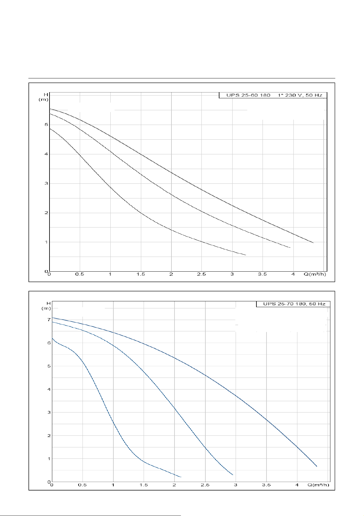
Technical Data
Integrated pumps, compact heat pumps
Heating pumps
AEROTOP T07C/T07CX: GRUNDFOS
Delivery height
Pumped Fluid = Water
Fluid Temperature = 20 °C
Density = 998.2 kg/m3
AEROTOP T10C/T10CX/T12C: GRUNDFOS
Delivery height
Pumped Fluid = Water
Fluid Temperature = 20 °C
Density = 998.2 kg/m3
977.8
70
24
Page 25
Technical Data
Remaining pump pressure circulation pump
Remaining pump pressure AEROTOP T07C
Pump pressure (kPa)
Pump pressure (kPa)
Flow rate (l/h)
Remaining pump pressure AEROTOP T10C
Flow rate (l/h)
Remaining pump pressure AEROTOP T12C
Pump pressure (kPa)
Flow rate (l/h)
25
Page 26
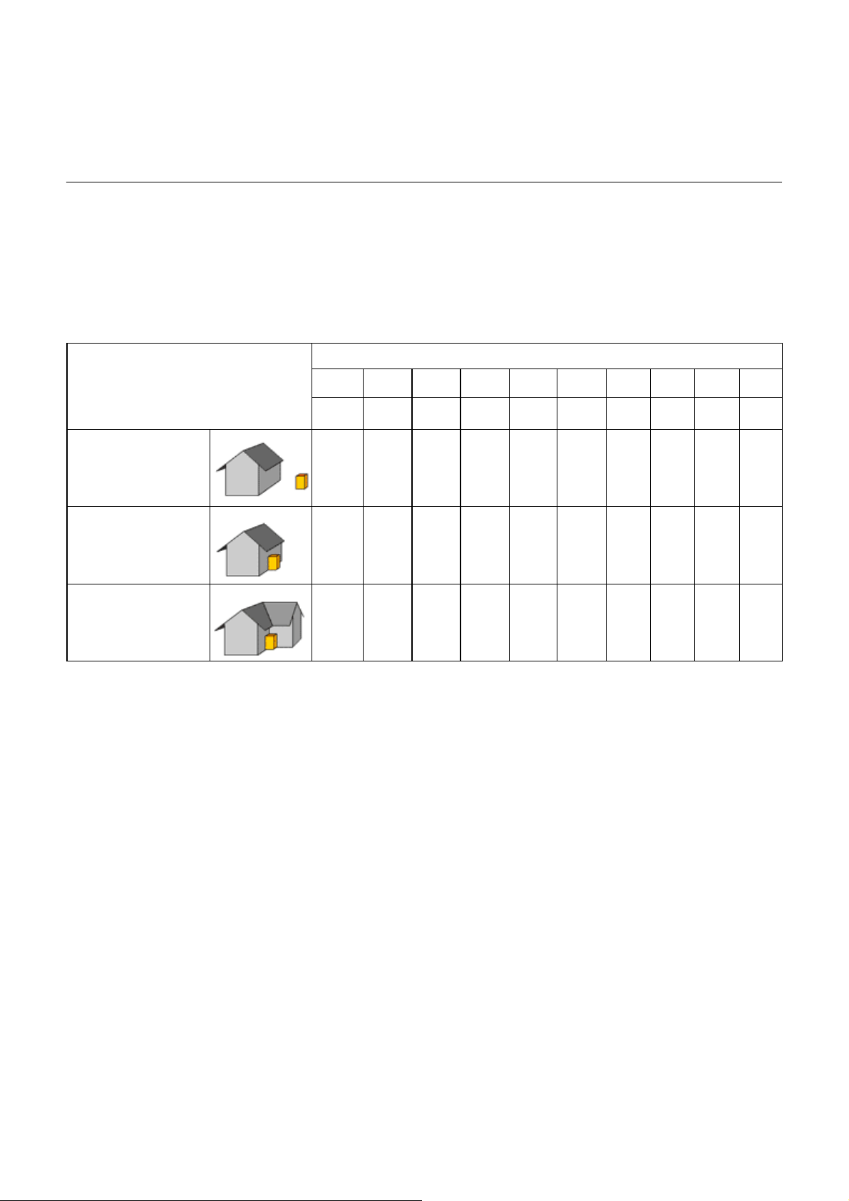
Technical Data
Noise Level
Sound AEROTOP T heat pumps
All ELCO-heat pumps are designed for
low-noise operation. However, the
setup location for the heat pumps
should be selected in a way that noise
pollution is avoided.
Inlet/outlet air shaft or
heat pump is detached
(min. 5 m distance to
any wall)
Inlet/outlet air shaft or
heat pump is situated
on a wall
Inlet/outlet air shaft or
heat pump is situated
in a corner
-8 -14 -20 -24 -26 -28 -30 -32 -34 -38
-5 -11 -17 -21 -23 -25 -27 -28 -31 -35
-2 -8 -14 -18 -20 -22 -24 -25 -28 -32
Reduction table for sound:
This table can be used to estimate the noise level at the measuring location on
the basis of the noise level at the emission location (noise level according to
page 16 and 17). Depending on the legal requirements, further correction factors
have to be considered. In cases of doubt, the emission values should be
calculated by an acoustic specialist.
Distance between emission location and measuring location [m]
1 2 4 6 8 10 12 15 20 30
dB(A) dB(A) dB(A) dB(A) dB(A) dB(A) dB(A) dB(A) dB(A) dB(A)
26
Page 27

Checklist
Correct Installation of an Air-Water Heat Pump
AEROTOP T heat pumps are quiet
and efficient. However, incorrectly
integrating constructional components
may result in undesired noise increases
if the conditions are unfavorable.
A careful assessment of the noise
emissions is required when planning
the installation of heat pump systems.
To be considered when installing an air-water heat pump
Each reflecting surface doubles
the noise (acoustic power).
One wall increases this value by
+3dB, one corner by +6dB.
Rooms with reverberant or
sound-reflecting floor coverings
and walls increase the noise
level.
Be careful with dropping the
washing
Adherence with the min.
clearances reduces noise
reflection and air short-circuits
and improves airflow near the fan.
Construction measures can
reduce noise, plants cannot.
Noise reduction measures considered
early on in the development process
result in the fewest additional costs.
Subsequent measures usually are
extremely expensive and cumbersome
to implement. [Heat Pump Manual,
Federal Energy Agency, Switzerland]
The following points apply to the
interior and exterior installation of
air-water heat pumps.
one corner by +6dB.
Avoid solid-borne noise transmission by avoiding reflecting surfaces. Never route air
intake or outlet into closed or partially closed spaces such as a corner, foyer, entrance
area, covered patio, etc.
Avoid rooms with reverberant or sound-reflecting floor coverings and walls. When
installing the heat pump in a room with reverberant or sound-reflecting floor coverings
and walls, reflections may increase the sound level. Cover one or two walls with
noise-absorbing material if this is the case.
Dropping the washing from lived-in rooms to the place of installation of the heat pump
can lead to noise transmission when unfavourably positioned.
Make sure the min. distances and clearances to the air intake and outlet as well as the
min. size of the light wells are applied. Avoid walls or flow barriers around the
circumference of the heat pump to ensure air can reach the fan evenly.
Less pressure losses = low peripheral speed = reduction of the fan noise.
Use constructional measures to interrupt the flow of noise from the heat pump
(direct noise propagation). Use solid walls, fences, palisades, etc. to reduce noise
levels. Plants, however, do not reduce noise.
Consider different noise
sensitivity levels.
Sound absorbing materials
reduce noise.
Separation from the structure
minimizes structure-borne
sounds.
Correct installation of pedestal
or base reduces structure-borne
sounds.
Correct installation of the ducts
reduces air and structure-borne
noise transference.
Avoid air short-circuits and airflow
barriers.
Always comply with all rules,
regulations, and applicable laws.
Avoid placing the heat pump where it may cause problems due to its noise emission
(bedrooms, living rooms, neighbors, etc.). Position heat pumps in areas where noise is
less likely to be an annoyance. If installed indoors, do not install underneath or next to
living or sleeping quarters.
Additional sound absorbing materials or measures must be planned for and used in
cases where extreme noise reductions are desired or when installing model Forever
GREEN 20C or later. Use only original accessories and spare parts. in extreme cases,
it may be advisable to consult a noise expert.
Always use flexible connections throughout: Flexible hoses and tubes for heat
distribution, flexible electrical connections, sound isolation of the air ducts by using
elastic sleeves or Compriband products.
The base or ground must be level or made level and able to support the load of the
equipment. Use the adjustable feet of the heat pump to level the equipment after
installation.
All wall openings and ducts must be equipped with the corresponding noise-absorbing
materials. Comply with the specified cross-sections and dimensions.
Air intakes and outlets cannot be installed next to each other without using a
separating wall. Avoid any airflow obstacles that favor an air short-circuit.
Germany: Technical Instructions on Noise
S
witzerland: Noise Protection Ordinance
27
Page 28

Performance Data
AEROTOP T07 – T16 (Information according to EN 14511)
Type Series
Ser i e
T
T
K
L
°C °C kW kW - kW kW - kW kW - kW kW kW kW
20
15
10
7
35
40
45
50
4
2
0
-4
-7
-10
-15
20
15
10
7
4
2
0
-4
-7
-10
-15
20
15
10
7
4
2
0
-4
-7
-10
-15
20
15
10
7
4
2
0
-4
-7
-10
AEROTOP T 07 AEROTOP T 10 AEROTOP T12 AEROTOP T14 AEROTOP T16
QPCOPQPCOPQPCOPQPCOPQPCOP
12.22.1 5.818.33.1 6.019.53.7 5.323.04.3 5.323.44.6 5.1
10.62.1 5.115.53.0 5.217.13.5 4.820.24.2 4.920.64.3 4.7
9.2 2.0 4.513.32.9 4.614.73.5 4.217.54.0 4.4 17.84.1 4.3
7.9 2.0 3.911.52.9 4.013.23.4 3.915.83.9 4.0 16.24.0 4.0
6.9 2.0 3.510.02.8 3.612.13.4 3.614.63.9 3.7 14.93.9 3.8
6.3 1.9 3.2 9.1 2.8 3.3 11.4 3.3 3.4 13.7 3.9 3.5 14.1 3.9 3.6
6.1 2.0 3.1 8.8 2.8 3.2 10.9 3.4 3.2 13.1 3.9 3.3 13.4 3.9 3.4
5.7 2. 0 2. 8 8. 3 2. 9 2.9 9. 7 3.4 2 .9 11. 7 4. 0 3. 0 12. 1 3. 9 3.1
5.4 2. 0 2. 6 7. 8 2. 9 2.7 8. 9 3.4 2 .6 10. 7 4. 0 2. 7 11. 1 3. 9 2.9
4.7 2. 0 2. 3 6. 9 2. 9 2.4 8. 3 3.4 2 .4 10. 1 4. 0 2. 5 10. 4 3. 9 2.7
3.52.01.85.22.81.87.33.52.19.04.12.2 9.33.92.4
11.62.4 4.917.33.4 5.119.04.1 4.622.54.8 4.722.95.0 4.6
10.22.3 4.415.03.4 4.516.84.0 4.219.94.7 4.320.34.8 4.2
9.1 2.3 3.913.13.3 4.014.53.9 3.717.34.5 3.8 17.74.6 3.8
8.1 2.3 3.511.83.3 3.613.33.8 3.515.94.4 3.6 16.34.4 3.7
7.1 2.3 3.110.33.2 3.212.23.8 3.214.64.5 3.3 15.04.5 3.3
6.5 2.3 2.9 9.4 3.2 2.9 11.5 3.8 3.0 13.8 4.5 3.1 14.2 4.5 3.2
6.2 2.3 2.7 9.1 3.2 2.8 10.9 3.8 2.8 13.1 4.5 2.9 13.5 4.5 3.0
5.7 2. 3 2. 5 8. 4 3. 3 2.6 9. 8 3.9 2 .5 11. 8 4. 5 2. 6 12. 1 4. 5 2.7
5.4 2. 3 2. 3 7. 8 3. 3 2.4 8. 9 3.9 2 .3 10. 8 4. 6 2. 4 11. 1 4. 5 2.5
4.7 2. 3 2. 0 6. 9 3. 3 2.1 8. 3 3.9 2 .1 10. 1 4. 6 2. 2 10. 4 4. 5 2.3
3.62.31.55.33.31.67.23.91.88.84.61.9 9.14.52.0
11.02.6 4.216.33.7 4.318.64.5 4.122.05.3 4.122.55.5 4.1
9.9 2.6 3.814.43.7 3.916.54.4 3.719.65.2 3.8 20.05.3 3.8
8.9 2.6 3.412.93.7 3.514.44.4 3.317.25.1 3.4 17.65.1 3.4
8.35 2 .62 3.2 12.0 3.7 3. 3 13.4 4.2 3 .2 15.9 4.9 3. 3 16. 4 4. 8 3.4
7.3 2.6 2.810.63.7 2.912.24.3 2.814.65.0 2.9 15.05.0 3.0
6.7 2.6 2.6 9.8 3.7 2.7 11.6 4.3 2.7 13.9 5.0 2.8 14.2 5.0 2.8
6.4 2.6 2.5 9.4 3.7 2.5 11.0 4.3 2.5 13.2 5.1 2.6 13.6 5.0 2.7
5.8 2. 6 2. 2 8. 5 3. 7 2.3 9. 9 4.4 2 .3 11. 9 5. 1 2. 3 12. 2 5. 1 2.4
5.4 2. 7 2. 0 7. 8 3. 7 2.1 9. 0 4.4 2 .1 10. 9 5. 2 2. 1 11. 2 5. 1 2.2
4.7 2. 7 1. 8 6. 9 3. 7 1.8 8. 3 4.4 1 .9 10. 1 5. 2 1. 9 10. 3 5. 2 2.0
3.62.71.45.43.71.47.14.41.68.75.21.7 8.95.21.7
10.42.9 3.615.34.1 3.718.15.0 3.621.55.8 3.722.06.0 3.7
9.6 2.9 3.313.94.1 3.416.24.9 3.319.35.7 3.4 19.85.8 3.4
8.8 2.9 3.012.74.1 3.114.34.8 3.017.15.6 3.0 17.55.6 3.1
8.3 2.9 2.812.04.1 2.913.34.7 2.815.85.5 2.9 16.35.4 3.0
7.5 2.9 2.510.84.1 2.612.24.8 2.614.75.6 2.6 15.05.6 2.7
7.0 2.9 2.410.14.1 2.511.64.8 2.414.05.6 2.5 14.35.6 2.6
6.6 2.9 2.2 9.6 4.1 2.3 11.1 4.8 2.3 13.3 5.6 2.4 13.6 5.6 2.4
5.9 3. 0 2. 0 8. 6 4. 1 2.1 9. 9 4.8 2 .0 12. 0 5. 7 2. 1 12. 3 5. 7 2.2
5.3 3. 0 1. 8 7. 8 4. 2 1.9 9. 1 4.9 1 .9 11. 0 5. 7 1. 9 11. 2 5. 7 2.0
4.7 3. 0 1. 6 6. 9 4. 2 1.7 8. 3 4.9 1 .7 10. 0 5. 8 1. 7 10. 3 5. 8 1.8
T
Water outlet temperature (flow)
K
in °C
TL Air intake temp. in °C
Q Heat output in kW
The power consumption of the fan and
the circulation pumps as well as the
defrosting function must generally be
considered as well.
Heating water flow and air flow are acc.
to specifications listed on the Technical
Data pages.
P Power consumption in kW
COP Performance rating
28
Page 29

Performance Data
AEROTOP T20 – T35 (Information according to EN 14511)
Type Series
Seri e
T
K
°C °C kW kW - kW kW - kW kW - kW kW
35
40
45
50
-10
-15
-10
-15
-10
-15
-10
T
L
20
15
10
7
4
2
0
-4
-7
20
15
10
7
4
2
0
-4
-7
20
15
10
7
4
2
0
-4
-7
20
15
10
7
4
2
0
-4
-7
AEROTOP T20 AEROTOP T26 AEROTOP T32
Q P COP Q P COP Q P COP Q P COP
27.5 6 .6 4.2 37.1 7.7 4.8 45.8 9.4 4 .9 48.6 10.6 4.6
25.3 6 .4 4.0 34.7 7.7 4.5 42.9 9.3 4 .6 44.7 10.2 4.4
23.1 6 .1 3.8 32.4 7.7 4.2 40.0 9.2 4 .3 40.8 9. 8 4.1
21.7 6 .0 3.6 29.9 7.6 3.9 36.8 8.9 4 .2 38.4 9. 6 4.0
19.7 5 .9 3.3 27.0 7.5 3.6 32.3 8.8 3 .7 34.8 9. 3 3.7
18.3 5 .8 3.2 23.7 7.4 3.2 29.3 8.8 3 .3 32.4 9. 2 3.5
17.5 5 .8 3.0 22.7 7.4 3.1 28.0 8.8 3 .2 30.9 9. 1 3.4
15.7 5 .7 2.8 20.7 7.4 2.8 25.6 8.8 2 .9 27.8 8. 9 3.1
14.4 5 .6 2.6 19.2 7.4 2.6 23.7 8.7 2 .7 25.4 8. 7 2.9
13.5 5 .5 2.5 18.4 7.6 2.4 21.8 8.7 2 .5 23.8 8. 5 2.8
11.6 5 .3 2.2 16.6 7.4 2.2 18.7 8.7 2 .2 20.4 8. 1 2.5
27.3 7 .1 3.9 36.7 8.6 4.3 45.3 10.5 4 .3 48.0 11.4 4.2
25.0 6 .8 3.7 34.3 8.6 4.0 42.3 10.4 4 .1 44.2 11.1 4.0
22.9 6 .6 3.5 31.9 8.5 3.7 39.4 10.3 3 .8 40.4 10.7 3.8
21.1 6 .5 3.3 29.4 8.4 3.5 36.2 10.0 3 .6 37.4 10.3 3.6
19.7 6 .4 3.1 27.1 8.4 3.2 32.4 9.9 3 .3 34.7 10.1 3.4
18.4 6 .3 2.9 24.3 8.3 2.9 30.0 9.9 3 .0 32.5 10.0 3.3
17.5 6 .2 2.8 23.2 8.3 2.8 28.7 9.9 2 .9 30.9 9. 8 3.1
15.8 6 .1 2.6 21.1 8.3 2.5 26.0 9.9 2 .6 27.7 9. 6 2.9
14.4 6 .0 2.4 19.5 8.3 2.3 24.1 9.8 2 .4 25.3 9. 4 2.7
13.4 5 .9 2.3 18.5 8.5 2.2 22.0 9.7 2 .3 23.5 9. 1 2.6
11.5 5 .6 2.0 16.6 8.5 2.0 18.8 9.9 1 .9 20.2 8. 6 2.3
27.0 7 .6 3.6 36.2 9.5 3.8 44.7 11.6 3 .9 47.5 12.3 3.9
24.8 7 .3 3.4 33.8 9.5 3.6 41.8 11.5 3 .6 43.7 11.9 3.7
22.6 7 .1 3.2 31.5 9.4 3.3 38.9 11.4 3 .4 39.9 11.5 3.5
20.5 6 .9 3.0 28.8 9.2 3.1 35.5 11.2 3 .2 36.4 11.1 3.3
19.6 6 .8 2.9 27.2 9.3 2.9 32.5 11.0 2 .9 34.5 10.9 3.2
18.5 6 .7 2.7 24.9 9.3 2.7 30.8 11.0 2 .8 32.5 10.7 3.0
17.6 6 .7 2.6 23.8 9.3 2.6 29.4 11.0 2 .7 30.9 10.6 2.9
15.8 6 .5 2.4 21.5 9.3 2.3 26.5 11.0 2 .4 27.6 10.3 2.7
14.5 6 .4 2.3 19.8 9.2 2.1 24.4 10.9 2 .2 25.2 10.0 2.5
13.3 6 .2 2.1 18.6 9.3 2.0 22.1 10.7 2 .1 23.2 9.7 2.4
11.5 6 .0 1.9 16.6 9.5 1.7 18.8 11.2 1 .7 19.9 9.2 2.2
26.7 8 .0 3.3 35.8 10.4 3.4 44.1 12.7 3.5 47.0 13.2 3.6
24.6 7 .8 3.1 33.4 10.3 3.2 41.2 12.6 3.3 43.2 12.7 3.4
22.4 7 .6 3.0 31.1 10.3 3.0 38.4 12.6 3.1 39.5 12.3 3.2
20.8 7 .4 2.8 29.0 10.2 2.8 35.8 12.5 2.9 36.6 12.0 3.1
19.6 7 .3 2.7 27.3 10.3 2.7 33.1 12.4 2.7 34.4 11.7 2.9
18.6 7 .2 2.6 25.5 10.2 2.5 31.5 12.4 2.6 32.5 11.5 2.8
17.7 7 .1 2.5 24.3 10.2 2.4 30.0 12.3 2.4 30.9 11.3 2.7
15.8 6 .9 2.3 21.9 10.2 2.2 26.9 12.3 2.2 27.6 11.0 2.5
14.5 6 .8 2.1 20.1 10.2 2.0 24.9 12.3 2.0 25.1 10.7 2.4
13.2 6 .6 2.0 18.7 10.2 1.8 22.8 12.1 1.9 23.0 10.3 2.2
AEROTOP T35
T
Water outlet temperature (flow)
K
in °C
TL Air intake temp. in °C
Q Heat output in kW
The power consumption of the fan and
the circulation pumps as well as the
defrosting function must generally be
considered as well.
Heating water flow and air flow are acc.
to specifications listed on the Technical
Data pages.
P Power consumption in kW
COP Performance rating
29
Page 30

Performance Data
AEROTOP T07X – T10X (Information according to EN 14511)
Serie
Type Series
T
K
°C °C kW kW - kW kW -
35
40
45
50
T
Water outlet temperature (flow)
K
T
20
15
10
-4
-7
-10
-15
20
15
10
-4
-7
-10
-15
20
15
10
-4
-7
-10
-15
20
15
10
-4
-7
-10
L
7
4
2
0
7
4
2
0
7
4
2
0
7
4
2
0
in °C
TL Air intake temp. in °C
Q Heat output in kW
P Power consumption in kW
COP Performance rating
AER OTOP T07 X AEROTOP T10 X
QPCOPQPCOP
12.2 2 .1 5.8 18.3 3.1 6.0
10.6 2 .1 5.1 15.5 3.0 5.2
9.2 2 .0 4.5 13.3 2.9 4.6
7.9 2 .0 3.9 11.5 2.9 4.0
6.9 2 .0 3.5 10.0 2.8 3.6
6.3 1 .9 3.2 9.1 2.8 3.3
6.1 2 .0 3.1 8.8 2.8 3.2
5.7 2 .0 2.8 8.3 2.9 2.9
5.4 2 .0 2.6 7.8 2.9 2.7
4.7 2 .0 2.3 6.9 2.9 2.4
3.5 2 .0 1.8 5.2 2.8 1.8
11.6 2 .4 4.9 17.3 3.4 5.1
10.2 2 .3 4.4 15.0 3.4 4.5
9.1 2 .3 3.9 13.1 3.3 4.0
8.1 2 .3 3.5 11.8 3.3 3.6
7.1 2 .3 3.1 10.3 3.2 3.2
6.5 2 .3 2.9 9.4 3.2 2.9
6.2 2 .3 2.7 9.1 3.2 2.8
5.7 2 .3 2.5 8.4 3.3 2.6
5.4 2 .3 2.3 7.8 3.3 2.4
4.7 2 .3 2.0 6.9 3.3 2.1
3.6 2 .3 1.5 5.3 3.3 1.6
11.0 2 .6 4.2 16.3 3.7 4.3
9.9 2 .6 3.8 14.4 3.7 3.9
8.9 2 .6 3.4 12.9 3.7 3.5
8.35 2 .62 3.2 12.0 3.7 3.3
7.3 2 .6 2.8 10.6 3.7 2.9
6.7 2 .6 2.6 9.8 3.7 2.7
6.4 2 .6 2.5 9.4 3.7 2.5
5.8 2 .6 2.2 8.5 3.7 2.3
5.4 2 .7 2.0 7.8 3.7 2.1
4.7 2 .7 1.8 6.9 3.7 1.8
3.6 2 .7 1.4 5.4 3.7 1.4
10.4 2 .9 3.6 15.3 4.1 3.7
9.6 2 .9 3.3 13.9 4.1 3.4
8.8 2 .9 3.0 12.7 4.1 3.1
8.3 2 .9 2.8 12.0 4.1 2.9
7.5 2 .9 2.5 10.8 4.1 2.6
7.0 2 .9 2.4 10.1 4.1 2.5
6.6 2 .9 2.2 9.6 4.1 2.3
5.9 3 .0 2.0 8.6 4.1 2.1
5.3 3 .0 1.8 7.8 4.2 1.9
4.7 3 .0 1.6 6.9 4.2 1.7
The power consumption of the fan and
the circulation pumps as well as the
defrosting function must generally be
considered as well.
Heating water flow and air flow are acc.
to specifications listed on the Technical
Data pages.
30
Page 31

Performance Data
AEROTOP T07R – T16R (according to EN 14511-Coolong)
The power consumption of the fan and
the circulation pumps as well as the
defrosting function must generally be
considered as well. Heating water flow and air flow are acc.
Water outlet temperature (flow)
Air intake temp. in °C
K
L
T
in °C
T
Q Heat output in kW
P Power consumption in kW
to specifications listed on the Technical
Data pages.
COP Performance rating
31
Page 32

Performance Data
AEROTOP T20R – T35R (according to EN 14511-Cooling)
32
The power consumption of the fan and
the circulation pumps as well as the
defrosting function must generally be
The power consumption of the fan and
considered as well. Heating water flow and air flow are acc.
the circulation pumps as well as the
defrosting function must generally be
considered as well. Heating water flow and air flow are acc.
Water outlet temperature (flow)
Water outlet temperature (flow)
Air intake temp. in °C
Air intake temp. in °C
K
L
K
L
T
in °C
T
in °C
T
Q Heat output in kW
T
P Power consumption in kW
Q Heat output in kW
P Power consumption in kW
to specifications listed on the Technical
Data pages.
to specifications listed on the Technical
Data pages.
COP Performance rating
COP Performance rating
Page 33

Setup and Connection Instructions
Safety, Transport and Installation
Safety Information
• Compliance with all rules and
instructions of all documentation,
labels, type plates, and associated
documents of the unit is
mandatory.
Transport
• When receiving the shipment, the
heat pump must be checked for
completeness as per order
confirmation .In case of damaged
or missing material, the carrier
must be informed in writing
immediately.
• Care and due diligence are
required during transport, setup,
preparation, or when handling
heavy materials that may damage
the heat pump.
• Make sure that towing ropes, belts,
or chains used for transport or
installation do not damage the heat
pump. Do not allow the heat pump
to swing back and forth when lifting
it up. Never tilt the heat pump more
than 15° from its vertical axis.
• The heat pump is affixed to a pallet
at the factory for transport and
covered with a protective film to
protect the unit from scratches. Do
not remove the packaging until the
heat pump is positioned at its final
location.
Setup
• Setup must be carried out carefully
and accurately.
• AEROTOP T heat pumps can be
installed on a level interior floor
without pedestal or base.
If installed outdoors, a pedestal or
base is required unless the
substrate is very firm and can
support the load.
• The installation room must have at
least one exterior wall. Rooms with
high humidity are unsuitable as
installation locations for
AEROTOP T heat pumps. A
condensate drain must be
available.
• The heat pump must be set up on
a level ground and aligned with the
adjustable feet. Make sure there is
sufficient space to access the
control panel and at the sides for
inspections and maintenance.
• Make sure the ground is able to
support the load of the heat pump
and all accessories. The floor or
ground must be free of dust and
other foreign particles. If installing
in the basement, make sure the
selected installation position
cannot be flooded.
• The heat pumps may not be placed
on floating floorings.
• Once moved to its final location,
the heat pump must be carefully
unpacked and removed from the
pallet. Protect heat pump from
impact and other damaging forces!
Installation
• The safety regulations and
schemes/diagrams must be strictly
observed.
• The accessories and additional
equipment must be installed by a
trained service technician (heating
contractor) as per the enclosed
assembly and installation
instructions.
• The noise emissions of the
AEROTOP T heat pump are very
low thanks to the sound-absorbing
materials used to mount the mobile
parts and the insulating cladding.
The effective noise value depends
also on the size of the installation
room, the noise-absorbance or
reflection of the materials in the
room, as well as the possibility of
the noise to spread and transfer
via solid bodies, among others.
• Air ducts, pipes, and electrical lines
must be attached to the masonry
and not the heat pump.
• All of these connections must be
established using flexible
connections so that they can swing
freely, especially when the
compressor or evaporator starts
up. Only then is it possible to avoid
transference of sound from solid
bodies to the building structure as
well as line breakages.
Observe the checklist notes when
selecting the installation site for the
correct setup of an air-water heat
pump
33
Page 34

Setup and Connection Instructions
Electrical Connections, Installation Types,
Hydraulic Connections, Condensate Drain
Electrical Connections and Control
Information
The electrical connections must be
established in compliance with local
rules and regulations. The current feed
may exhibit a max. tolerance of 2% with
this power intensity when a voltage of
10% exists. Do not connect the heat
pump if the phase difference exceeds
more than 2%. Operating the
equipment outside of the listed limit
values will void the warranty. If
necessary, please contact your local
electricity company or utility.
The internal wiring of the heat pump is
carried out at the factory as listed on
the electrical diagram included with
the unit.
The heat pump is equipped with an
electrical supply box containing the
components listed below.
• Heat pumps and system controller
unit
• Elements to feed the
corresponding components of the
heat pump.
An automatic cutout switch or a
3 phase, slow-blow fuse with neutral
conductor must be provided externally
in compliance with the technical
requirements of this documentation.
The low voltage cables (control) may
not be placed in the same cable c
onduits or ducts as the supply cables.
The exterior temperature sensor of the
controller must be attached to the
outside wall of the building in a location
protected from the afternoon sun and
other heat sources (open windows,
chimneys, etc.).
Northern and northeastern exposures
are preferred.
If the room impact is to be activated for
a remote control, this control unit must
be placed in a reference room
(e.g. living room) where it cannot be
influenced by an external heat source
(e.g. stoves, heaters, air flow, etc.).
Indoor Installation
If installed indoors, AEROTOP T heat
pumps do not require base or pedestal.
All heat pump models T20 – T35
must be equipped with noise
dampers for air intake and air outlet.
Outdoor Installation
If the heat pump AEROTOP is installed
outdoors, the heating pipes and ducts
must be as short as possible and they
must be well insulated. Place the heat
pump on a level and solid surface with
the necessary bearing capacity. The
corresponding accessories needed for
the outdoor installation must be ordered
as well.
Heating System Hydraulic
Connections
AEROTOP T heat pumps can be
connected in any desired layout. The
hydraulic connections require flexible
ducts to avoid noise transference from
pipe openings and solid bodies to the
distributor network and from there to
the heating elements such as radiators,
etc. The ducts can be directed from the
right or left and are connected to the
inside of the heat pump.
The ductwork must be carried out in
such a way that pressure drops at the
nominal volume flow do not exceed the
available pressure since this would
result in a reduction of the heat pump
output.
This means that ducts cannot have
elbows that are too narrow.
Pipes and du
insulated to prevent unnecessary heat
loss and the formation of condensate,
which could damage the pipe and duct
system or the installation location.
cts must also be sufficient
For each heat pump we offer hydraulic
standard schemes. The integration of
these variants guarantee a safe and
faultless operation.
The system must be thoroughly
flushed before connecting to the heat
pump.
Residues in the heat pipes lead to
damages on the heat exchangers und
to malfunction of the heat pump.
Especially if there is no buffer storage
it is recommended to a dirt trap in the
heating return flow.
The water filled into the heating system
must be handled in accordance with the
rules and regulations of the relevant
professional associations.
It is important to ventilate the heating
system. If not the correct operation of
the heat pump is affected. Therefore
an exhauster must be provided. The
compact heat pumps have an
exhauster installed in the flow.
Condensate Drain
The condensate drain should be as
close to the heat pump connection as
possible. To prevent room air or c
analization waste air from being sucked
into the heat pump, the condensate
drain must be connected airtight to the
heat pump using a siphon with a min.
height of 100 mm. The condensate
drainage pipe cross-section may not be
reduced and must be at a continuous
2% incline to ensure water can be
ufficiently drained.
34
Page 35

Commissioning
Conditions, parameterization,
maintenance
Requirements for Initial Startup
(Commissioning)
The initial startup of the AEROTOP T
heat pump must be carried out by our
qualified technicians or the warranty
will become void.
Operating the heat pump is prohibited
if the following conditions exist::
• Construction drying
• System/unit used in unfinished
buildings
• Windows or exterior doors
unfinished and locked.
These cases require the use of a
specific construction heating system.
Functional heating or surface-ready
heating with the heat pump acc. To
DIN EN 1264 is only permitted when
complying with these conditions.
Furthermore, it must be noted that the
design of the heat pump concerning its
standard operation may not yield the
full extent of the required heat output.
The following notes must be observed
as well:
The corresponding rules and regulations of the floor/screed manufacturer!
Proper function is only ensured with a
correctly installed system (hydraulics,
electrical, settings)! Deviations may
damage the floor/screed!
Ensure the following points are
implemented and checked before the
initial startup of the heat pump:
• The control box is installed and
completely connected.
• The heat pump is professionally
and completely installed (hydraulics
and electrical).
• All external system components
required for operating the heat
pump (circulation pumps, three-way
valves, sensors, etc.) are
completely and professionally
connected.
• The hydraulic connections have
been established completely and
professionally.
• All sensors are professionally
installed, shielded, and positioned
in the correct locations as outlined
by the respective system scheme.
• The heating system is pro-
fessionally installed and has been
flushed, charged, vented, and
checked for leaks as per rules and
regulations.
• The electrical voltage meets the
requirements listed on the type
plate of the heat pump.
• All fittings are in operational position.
The following persons must be
present to carry out the initial
startup process:
• The planer; he or she must indicate
the operational parameters.
• The installer; he or she is
responsible for the functionality
and settings of the hydraulic
system.
• The system maintainer (customer
or representative); he or she will
be instructed in the operation and
functions of the system.
If an initial startup is requested without
all of these conditions having been met,
ELCO rejects any responsibility for
system malfunctions or other
operational problems. In this case, the
system is operated at the risk and
responsibility of the owner.
Parameterization
The heat pump and the entire system is
controlled with the integrated LOGON B
WP61 controller. Please consult the
system documentation for the correct
parameter settings.
After the Initial Startup
After the initial startup is finished, the
AEROTOP T heat pump does not
equire any additional interventions or
adjustments to the controller. Any
desired heating temperature
adjustments can be made in
accordance with the enclosed user
manual for the LOGON B WP61
controller.
Controller Function
Different temperature sensors and ¨
measuring elements in the heat pump,
at the exterior air, in the system, in the
storage tank, in the hot water tank, and
possibly also in the living quarters are
used by the controller. If and as
needed, the controller passes a heat
demand signal to the heat pump.
The input of a heating curve is used
to control and adjust heating temperatures. The heat pump as well as the
system is controlled automatically.
The system-relevant parameters are
entered when commissioning the
climate-based controller.
Heat Pump Upkeep
The AEROTOP T heat pump does not
require any special upkeep. However,
it is important to keep the system clean
and in good working order. The
specified leak checks must be carried
out as well. From an energetic
viewpoint, it is also recommended,
especially in case of a new
construction, to have the heating
parameters checked and optimized by
a service technician during the second
winter after the initial startup since the
initial humidity has now evaporated
from the building and the required
heating output is less than initially.
Primary focus should be on keeping air
intake and outlet free of dust and other
foreign particles or objects. The air
intake and outlet openings must be
kept free of obstructions (e.g. leaves,
vehicles, debris).
Only trained and authorized service
technicians are permitted to service
AEROTOP T heat pumps.
The warranty becomes null and void if
the system or heat pump is serviced by
other persons or companies that are
not authorized to do so.
Error Messages
AEROTOP T heat pumps function
without problems as long as the
different parameters do not deviate
from the intended or specified values.
If one or several of these parameters
exceed the limit values, the controller
depicts the corresponding error in plain
text and stops the heat pump if required
to protect the different components.
The different error messages are
described in the LOGON B WP61 user
manual. The heat pump is released
again with some errors (automatic
acknowledgement) once the intended
status has been reached again. It is
also usually possible to release the
heat pump manually.
In order to ensure reliable
functionality of your system, we
recommend purchasing a maintenance/ service contract.
35
Page 36

Indoor Setup
Unit Dimensions, Indoor Setup
(With optional noise dampers )
Legend
1 Heater flow 1” ( 11/4” from T20) flexible
Hydraulic or electrical connections all left or right
2 Heater return flow 1” (11/4” from T20), flexible
3 Condensate drain ¾”, flexible
4 Air inlet (at the rear of the unit)
5 Air outlet (optional left, right or top)
6 Electrical connection
7 Vibration dampening rubber feet
SI + SO noise damper (optional)
AEROTOP T
T07C, T07
Width
A A+SO B C C+SI d e i j k t q
995 1570 1525 650 1225 575 910 210 300 390 100 40
Heigh Depth
Height
at bottom
Height
at Top
Hydraulic connections Feet
T10C, T10
T12C, T12, T14, T16
T20, T26
T32, T35
36
1095 1670 1575 750 1325 575 960 210 300 390 100 40
1195 1770 1675 750 1325 575 1060 210 300 390 100 40
1195 1770 1695 880 1455 670 975 230 385 545 110 50
1295 1870 1905 1000 1575 670 1185 230 385 545 110 50
Page 37

Indoor Installation
Unit Dimensions with Noise Dampers
With indoor installation all heat pump models can be equipped with noise dampeners.
Additional measures must be planned for.
Width Width Heigh
AEROTOP T
a b c e A C
T07C, T07 995 1525 650 910 1570 1225
T10C, T10 1095 1575 750 960 1670 1325
T12C, T12, T14,
T16
T20, T26 1195 1695 880 975 1770 1455
T32, T35 1295 1905 1000 1185 1870 1575
1195 1675 750 1060 1770 1325
Height at
Top
Dimensions with
Noise Damper
37
Page 38

Air Connections with Indoor Installation
Air Connections, Duct Lengths
Air Intake, Associated Unit Dimensions
Air Connections
Air intake and air outlet systems must
be protected with grating and kept
clean.
It is recommended that light wells are
insulated with a sound damping,
weather resistant material to prevent
dampness problems inside the house
The light wells must be drained. The
air intake and outlet openings must be
kept free of obstructions. Make sure
they are installed accordingly. Parking
lots or leaves accumulating in fall and
possibly suctioned into the system are
a problem.
Select the air outlet in such a way that
the emerging blast of air is not directly
pointed at people, animals, or plants.
The air suction and discharge must
not be oriented as the windflow. The
correct functioning could be compromised by the wind action.
Duct Length
The possible duct lengths are derived
from the available pressure and
the pressure loss indicated for the
respective accessories.
If the air ducts are more than 3 meters
long each side, an accurate design is required.
In wind exposed places the uncontrolled
airflow can be controlled by using shutters
Pressure Loss
Air duct, flexible Ø 500 0,5 - 1,4 Pa/m
flexible Ø 610 1,2 - 1,8 Pa/m
Rigid 750x750 0,5 Pa/m
Rigid 870x870 0,5 Pa/m
Elbow
Rigid750x750 4,2 - 6,9 Pa/m
Rigid 870x870 4,8 - 6 Pa/m
Light well ca 3,5 Pa
Mesh ca 1,5 Pa
Protective grating
AIR IN
AIR OUT 11 - 45 Pa
Slienziatori SI+SO T20 6+8 Pa
Slienziatori SI+SO T26 9+14 Pa
Slienziatori SI+SO T32 4+10 Pa
Slienziatori SI+SO T35 5+10 Pa
Slienziatori SI+SO T07 1+2 Pa
Slienziatori SI+SO T10 1+3 Pa
Slienziatori SI+SO T12 2+5 Pa
Slienziatori SI+SO T14-
T16
3 - 23 Pa
3+6 Pa
Due to the radial fan, the available
pressure is more than sufficient and
can be adjusted for all models T07 to
T16, as weel as all T..R, with LOGON B
WP61 heat pump controller to meet the
needs of the respective system. Please
comply with the fan speed setting
values (page 18).
Air Intake
The air intake (A) is at the rear of the
AEROTOP T. It is possible to place
the heat pump against the exterior wall
(use wall opening kit WAI). If this instal
lation type is not possible, use the air
intake box and a flexible duct to
connect to the heat pump. The duct
can then be directed to the left, right,
or the top.
Flexible ducts are not possible with
AEROTOP T 20 to 35 models and rigid
ducts must be used. These are to be
connected to the heat pump with a
flexible sleeve.
Noise dampers for air intake and air
outlet are recommended for
AEROTOP T20 to T35 heat pumps
according to page 35
AEROTOP
T07C, T07 995 1525 650 40 915 830 655 550 380 795 180 575
T10C, T10 1095 1575 750 40 1015 880 655 550 380 820 205 575
T12C, T12, T14, T16 1195 1675 750 40 1115 980 655 700 380 795 180 575
38
Width Width Heigh Profile
a b c f a1 e1 h l m r o u
Air Outlet With Wall
Installation
Air Intake with Intake
Box KWI
Page 39

Air Connections with Indoor Installation
Air Outlet, Associated Unit Dimensions
Air Outlet
If the heating or utility room has two
exterior walls, a space-saving corner
installation is ideal with the heat pump
being placed into the left or right corner.
This is possible since the air outlet (B)
can be mounted on the left or right side
(use wall opening kit).
If a corner installation is not possible
(e.g. because the room has only one
exterior wall or in case of an existing
building), use the panel to connect
a flexible duct. The alignment of the air
outlet sleeve can be directed to the
right (R), left, or top (T) as needed by
simply replacing the panel
If air intake and air outlet are connected
to the same building side (parallel
installation), it must be prevented that
emitted air is suctioned back into the
system by the heat pump (no air
short--circuit!).
Flexible ducts are not possible with
AEROTOP T 20 to 35 models and rigid
ducts must be used. These are to be
connected to the heat pump with a
flexible sleeve.
Noise dampers for air intake and air
outlet are recommended for Forever
AEROTOP T20 to T35 heat pumps
according to page 35.
AEROTOP T
T07C, T07 995 1525 650 40 570 830 655 550 380 795 180
T10C, T10 1095 1575 750 40 670 880 655 550 380 820 205
T12C, T12, T14, T16 1195 1675 750 40 670 980 655 700 380 795 180
T20, T26 1195 1695 880 40 800 895 760 - - - -
T32, T35 1295 1905 1000 40 920 1105 760 - - - -
39
Width Width Heigh Profile
a b c f c1 e1 h l m r o
Air Outlet With Wall
Installation
Air Outlet Via Flexible Duct
Page 40

Air Connections with Indoor Installation
AEROTOP T07 - T35 Corner Setup
AEROTOP T07 – T35 Corner Setup
If the heating or utility room has two
exterior walls, a space-saving corner
installation is ideal with the heat pump
being placed into the left or right corner.
Air ducts are not needed.
Left corner setup Right corner setup
Required Accessories:
- AIR IN wall setup kit
- AIR OUT wall setup kit
1) The compliance with acoustic limit
values must be clarified by
customer.
2) Necessary outside insulation by
customer, minimal clearance of
light well must not be gone below.
3) Possible air short-circuit to be
prevented by customer.
4) Statistics to be checked by
customer
AEROTOP T
T07C, T07 995 1525 650 950 600 640 860 60 1200 600 800 600
T10C, T10 1095 1575 750 1050 700 640 910 60 1200 600 1000 600
T12C, T12, T14, T16 1195 1675 750 1150 700 640 1010 60 1200 600 1000 600
T20, T26 1195 1695 880 1150 830 740 930 60 1400 800 1200 800
T32, T35 1295 1905 1000 1250 950 740 1140 60 1400 800 1200 800
The indicated cutouts apply only to the
accessories AIR IN and OUTLET wall
setup. The dimensions apply after all
tasks have been completed and refer to
40
Width
Widt
a
Heigh
h
b
finished floors.
c
• Statistics to be checked by
customer If necessary wall must be
reinforced with PUR- insulation
elements. This must be considered
for the cutouts
Dimensions Of Both Cutouts,
Without Insulation
a2 c2 d2 e2
Recommended Dimensions,
Light Well
a3 c3 a4 c4
x
• Possible air short-circuit to be
prevented by customer
• Necessary outside insulation to be
installed by customer
Page 41

Air Connections with Indoor Installation
AEROTOP T07-T35 with Noise Dampers (SI + SO) Corner Setup
AEROTOP T07 - 35 Corner Setup
The dimensions of the noise dampers
must be considered in addition when
placing heat pumps into a corner.
The heat pump can be placed in the
right or left corner. Air ducts are not
needed.
Required Accessories:
- AIR IN wall setup kit
- AIR OUT wall setup kit
- SI Noise damper
- SO Noise damper
1) The compliance with acoustic limit
values must be clarified by
customer.
2) Necessary outside insulation by
customer, minimal clearance of
light well must not be gone below.
3) Possible air short-circuit to be
prevented by customer.
4) Statistics to be checked by
customer
AEROTOP T
T07C, T07 995 1525 650 1570 1225 950 600 640 860 635 1200 600 800 600
T10C, T10 1095 1575 750 1670 1325 1050 700 640 910 635 1200 600 1000 600
T12, T14,
T16
T20, T26 1195 1675 880 1770 1455 1150 830 740 930 635 1400 800 1200 800
T32, T35 1295 1695 1000 1870 1575 1250 950 740 1140 635 1400 800 1200 800
The indicated cutouts apply only to the
accessories AIR IN and OUTLET wall
setup. The dimensions apply after all
tasks have been completed and refer
to finished floors.
41
Width Width Heigh
a b c A C a2 c2 d2 e2 x a3 c3 a4 c4
1195 1575 750 1770 1325 1150 700 640 1010 635 1200 600 1000 600
Dimensions With
Noise Dampers
• Statistics to be checked by
customer If necessary wall must
be reinforced with PUR- insulation
elements. This must be considered
for the cutouts
Dimensions Of Both Cutouts,
Without Insulation
• Possible air short-circuit to be
prevented by customer
• Necessary outside insulation to
be installed by customer
Minimal Dimensions,
Light Well
Page 42

Cutout Plans for Indoor Installation acc. to
SIA Standard
Wall Installation
WP = heat pump, MD = wall opening w/o insulation, Uk = from finished floor = cutout lower edge from finished floor
ab FFB = from finished floor *dimensions with noise damper SI and SO
AEROTOP T07 (C)
AEROTOP T10 (C)
AEROTOP T12 (C), 14, 16
AEROTOP T20, 26
AEROTOP T32, 35
42
Page 43

Air Connections with Indoor Installation
AIR IN and AIR OUT Wall Installation Accessories
AEROTOP T07-T35
AIR IN wall installation
AIR OUT wall installation
The wall opening can be made
either on the left or on the right
of the heat pump.
AEROTOP T07 – T35 with noise damper SI + SO
AIR IN wall installation AIR OUT wall installation
The wall opening can be made
either on the left or on the right
of the heat pump.
43
Page 44

Air Connections with Indoor Installation
Freely Selectable AIR IN
AEROTOP T07 - T16
The use of flexible air ducts offers a
variety of different air routing and
airflow options.
The flexible air out ducts are fastened
suction-side and with the intake box for
flexible air intake to the left or right side
of the heat pump.
The wall opening is insulated with the
corresponding insulation kit.
Necessary outside
insulation by customer
Flexible ducts are not possible with
AEROTOP T 20 to 35 models and rigid
ducts must be used. See also "Parallel
Setup with Rigid Duct."
Required Accessories:
- Freely selectable AIR IN with air
duct
- AIR OUT as needed, AIR OUT
wall installation or freely selectable
AIR OUT
The duct can also be mounted to the
left or at the top of the heat pump
1) The compliance with acoustic limit
values must be clarified by
customer.
2) Necessary outside insulation by
customer, minimal clearance of
light well must not be gone below.
3) Possible air short-circuit to be
prevented by customer.
5) Noise level of AIR OUT and AIR IN
must be considered separately
Cutouts Without Insulation
AEROTOP T
c2 e2 d2
T07C, T07 600 860 wählbar 620
T10C, T10 700 910 wählbar 620
T12C, T12, T14, T16 700 1010 wählbar 620
All dimensions refer to a finished floor and completed walls/masonry.
44
D2 with
rigid duct
Cutouts With
Insulation
e1 c1
800 540
850 640
950 640
Recommended Light
Well Dimensions
c3 e3
800 600
1000 600
1000 600
Page 45

Air Connections with Indoor Installation
Freely Selectable AIR OUT
AEROTOP T07 - T16
The use of flexible air ducts offers a
variety of different air routing and
airflow options. The flexible air out
ducts are fastened either to the left or
right side of the air out panel at the
heat pump.
The wall opening is insulated with the
corresponding insulation kit.
The duct can be
mounted on the left
or the top of the heat
pump as needed.
Flexible ducts are not possible
AEROTOP T 20 to 35 models and rigid
ducts must be used. See also "Parallel
Setup with Rigid Duct."
Required Accessories:
- Freely Selectable AIR OUT
- AIR IN as needed, AIR IN wall
installation or AIR IN freely
selectable
1) The compliance with acoustic limit
values must be clarified by
customer.
2) Necessary outside insulation by
customer, minimal clearance of
light well must not be gone below.
3) Possible air short-circuit to be
prevented by customer.
5) Noise level of AIR OUT and AIR IN
must be considered separately
Light well
Cutouts Without Insulation
AEROTOP T
c2 e2 d2
T07C, T07 600 860 wählbar 620 800 540 800 600
T10C, T10 700 910 wählbar 620 850 640 1000 600
T12C, T12, T14, T16 700 1010 wählbar 620 950 640 1000 600
All dimensions refer to a finished floor and completed walls/masonry.
45
D2 with
rigid duct
Cutouts With
insulation
e1 c1
Recommended Light
Well Dimensions
E3 width C3 depth
Page 46

Air Connections with Indoor Installation
Freely Selectable AIR OUT and AIR IN Accessories
(AEROTOP T07 to T16)
Corner installation option
All variants can also be installed
mirror-inverted
Parallel installation option
All variants can also be installed
mirror-inverted
46
Page 47

Air Connections with Indoor Installation
Parallel Setup with Rigid Duct
(without Noise Damper)
Required Accessories:
• AIR IN wall setup kit
• AIR OUT parallel installation with
rigid duct.
1) The compliance with acoustic
limit values must be clarified by
customer.
2) Necessary outside insulation by
customer, minimal clearance of
light well must not be gone
below.
3) Possible air short-circuit to be
prevented by customer.
5) Noise level of AIR OUT and
AIR IN must be considered
separately
Partition wall Height
k2 x Width k3
Light well
Light well dimension
a3 a4 c3 c4
T07C, T07 1200 800 600 600
T10C, T10 1200 1000 600 600
T12C, T12, T14, T16 1200 1000 600 600
Light well
or
or
All dimensions refer to a
finished floor and completed
walls/masonry.
Rigid Duct
Dimension
AEROTOP T
e1 c1 a2 c2 d2 e2
T07C, T07 800 520 950 600 640 860 1500 630 1500 1000
T10C, T10 850 620 1050 700 640 910 1500 630 1500 1000
T12C, T12, T14, T16 950 620 1150 700 640 1010 1800 630 1700 1200
47
Cutouts without Insulation
Distance between
Cutouts
k1 without
partition
wall
partition
Partition Wall
k1 with
Height k2 Width k3
wall
Page 48

Air Connections with Indoor Installation
Parallel Setup with Rigid Duct
(with Noise Damper)
Required Accessories:
Light well
• AIR IN wall setup kit
• AIR OUT parallel setup with rigid
duct
Partition wall Height
k2 x Width k3
Light well
• SI Noise damper
• SO Noise Damper
1) The compliance with acoustic
limit values must be clarified by
customer.
2) Necessary outside insulation by
customer, minimal clearance of
light well must not be gone
below.
3) Possible air short-circuit to be
prevented by customer.
5) Noise level of AIR OUT and
AIR IN must be considered
separately
or
or
Light well dimension
a3 a4 c3 c4
T07C, T07 1200 800 600 600
T10C, T10 1200 1000 600 600
T12C, T12, T14, T16 1200 1000 600 600
T20, T26 1400 1200 800 800
T32, T35 1400 1200 800 800
Rigid Duct
Dimension
AEROTOP T
e1 c1 f1 a2 c2 d2 e2
T07C, T07 800 520 575 950 600 640 860 1500 630 1500 1000
T10C, T10 850 620 575 1050 700 640 910 1500 630 1500 1000
T12C, T12, T14, T16 950 620 575 1150 700 640 1010 1800 630 1700 1200
T20, T26 870 750 575 1150 830 740 930 2000 630 1700 1200
T32, T35 1080 870 575 1250 950 740 1140 2200 630 1700 1500
All dimensions refer to a finished floor and completed walls/masonry.
48
Cutouts without Insulation
Distance between
Cutouts
k1 without
partition
wall
partition
k1 with
wall
Partition Wall
Height
k2
Width
k3
Page 49

Cutout Plans for Indoor Installation acc.
to SIA Standard
Parallel Setup With Rigid Duct
With / Without Noise Damper
WP = heat pump, MD = wall opening w/o insulation, Uk = from finished floor = cutout lower edge from finished floor
ab FFB = from finished floor
AEROTOP T07 (C)
AEROTOP T10 (C)
AEROTOP T12 (C), 14, 16
AEROTOP T20, 26
AEROTOP T32, 35
49
Page 50

Outdoor Setup
Unit Dimensions AEROTOP T.. Outdoor Setup
AEROTOP T20-T35
AEROTOP T..
Min. 1200 mm
AEROTOP T07-T16
Min. 800mm
4
AEROTOP T..
5
AEROTOP T..Outdoor setup :
Incl. Hoods for Air In / Air Out, protective roof and
regulating wall housing.
1 Flow line heater ø 1” (ø 11/4” from T20)
Hydraulic and electrical connections all at the
bottom
2 Return line heater ø 1” (ø 11/4” from T20)
3 Condensation water drain ø 3/4”
4 Air inlet
5 Air outlet
6 Electrical connections
a Electric line low voltage
b Electric line safety low voltage
7 Vibration dampening rubber feet
8 Protective roof with distance spacer
9 Setup foundation, minimum height 300 mm,
account for local snow heights.
AEROTOP T
T07 995 1513 650 1450 575 910 1095 750 28
T10 1095 1563 750 1650 575 960 1195 850 28
T12, T14, T16 1195 1663 750 1750 575 1060 1295 850 28
T20, T26 1195 1690 880 1980 670 975 1295 980 45
T32, T35 1295 1900 1000 2200 670 1185 1395 1100
Width
A B C C+ d e AS CS q
Height without
protective roof
Depth
Depth for
Minimum clearances for service works
Prevent air short circuits
Attention: a setup in the frontage corner leads to a
higher noise emission and should be avoided,
if possible!
The air discharge can’t be set directly on a wall. In
this case a minimum distance of 2 meters must be
respected.
The air suction and discharge must not be oriented
as the windflow. The correct functioning could be
compromised by the wind action.
Height without
protective roof
on top
foundation
ASS
Height
at bottom
Setup
Feet
45
AEROTOP T für Aussenaufstellung
50
50
Page 51

Outdoor Installation
Special Conditions, Installation Location
Special Rules for Outdoor Installations
Please observe the general setup, installation, and connection instructions.
Place the heat pump on a level and
solid surface with the necessary bearing
capacity. If not available, provide a
cement base, acc. to the snow height,
so that the feet of the outdoor unit
cannot be covered with snow. The heat
pump must be aligned with the adjustable feet.
Heater flow and return must be as short
as possible and well insulated to prevent
heat losses. The condensate drain must
be insulated and protected from frost
and have a siphon with a min. height of
100 mm routed into a closed drain.
The drain line must not have any crosssection reductions and must be sufficiently suitable to ensure problem-free
drainage.
The controller unit must be installed
inside of the building (temperature range
of +5°C to +40°C). The wall openings
for heater flow and return as well as the
electrical cables must be carried out
according to the rules and regulations.
Especially the flexible electrical cables
as well as the low voltage (230 or 400V)
and the extra-low voltage (sensor and
controller cable) must be shielded from
one another.
Information about Cables in Conduits (Min. Ø 70 mm)
1 EC block 2-pin Ø 5 mm
1 x malfunction 2-pin Ø 5 mm
1 x controller unit 3-pin Ø 7 mm
1 x room sensor 2-pin Ø 5 mm
7 x sensor 2-pin Ø 35 mm
1 x electr. feed 3 x 400 V 3-pin Ø 12 mm
1 x condenser pump 3-pin Ø 7 mm
1 x heating circuit pump 3-pin Ø 7 mm
1 x mixing valve 3-pin Ø 7 mm
1 x storage charge pump 3-pin Ø 7 mm
Heating Circuit 2
1 x heating circuit pump 3-pin Ø 7 mm
1 x mixing valve 4-pin Ø 10 mm
51
Selecting the Installation Site
Air intake and outlet must be kept
clean, unobstructed, and free of snow,
leaves, plants, machinery, etc. Comply
with min. clearances as specified for
air intake, outlet, misc. ducts, and
maintenance (see previous page).
Avoid an air short-circuit at all costs.
Use both sides for the air outlet if
strong winds, for example, may cause
an air short-circuit. The air intake must
be protected from aggressive or corrosive substances such as ammonia,
chlorinated substances, etc.
The AEROTOP T heat pump is very
quiet. However, since noise is perceived differently by different people,
the heat pump should not be installed
near windows, sleeping or living
quarters (porch, edge of pool, etc.).
The distance to neighboring houses
should be sufficient as well. It is not
advised to install the heat pump in
recesses (possible echo or air short-circuit). Local rules and regulations
apply.
Observe the checklist notes when
selecting the installation site for the
correct setup of an air-water heat
pump.
= Ø 57 mm
(conduit min. 70 mm)
= Ø 57 mm
(conduit min. 70 mm)
1
2
a
b
7
7
3
1 Heater flow
Hydraulic and electrical connections
are at the bottom side of the heat
pump.
2 Heater return
3 Condensate drain Ø 25/31 mm
4 Air intake
5 Air outlet
6 Internal electrical panel
7 Hydraulic and electrical connections,
electr. low voltage cable shielded
from 380V and 230V
8 Adjustable, noise-dampened feet
9 Protective cover
10 Base or pedestal, recommended height
of 200 mm, consider local snow
levels.
12 Wall opening slanted towards inside
with seal (in PE, inner diameter of 300
mm)
13 Controller unit for wall mounting
(included in delivery)
.
Ø 300mm
13
1
12
Page 52

Outdoor Installation
Base/Pedestal Plan
Cutouts in Base/Pedestal for
AEROTOP T07-T35
The base or pedestal should project
beyond each side of the heat pump for
about 50 mm and be approx. 300 mm
high (adjust to local snow conditions
as needed). A conduit (NW 250) must
be installed between building and heat
pump for the installation lines (electrical,
hydraulic, and condensate).
Setup Base/Pedestal
AEROTOP T a1 c1 h1
AEROTO T07-T16
Min. 800mm
T07
T10
T12, T14, T16
T20, T26
T32, T35
1095 750 300
1195 850 300
1295 850 300
1295 980 300
1395 1100 300
min. 50 mm
Ø 175
AEROTO T20 - T35
min. 500
Min. 800mm
242 mm
52
242 mm
c1
Ø 175 mm
a1
min. 500 mm
Page 53

Installation
Duct and Cable Bushing
1
Upper edge of base to
upper edge of conduit
min. 3 cm
Prepunched Opening for Outdoor
Installation of an Air-Water Heat
Pump
A prepunched opening (1) for the lines
routed from the rear of the enclosure
into the ground is provided in the unit
bottom behind the electrical panel.
We recommend routing the lines this
way for the heat pump installed
outdoors. This involves pulling the
heating lines, condensate connection,
and the electrical cables through the
opening.
Push conduit
against HP insulation
to protect from insects
Please take note of the base/pedestal
plan with the required cutout.
The prepunched cover can be lifted
with a screwdriver or detached with
sheet metal nippers.
Condensate drain also possible
via seepage pit.
Drain pipe insulation min. 3 cm
Upper edge of ground
to upper edge of base
min. 30 cm
Water-proof conduit (plastic pipe)
installed 800 to 1000 mm on-site underground with 2% tilt towards building.
Use only 45° elbows.
Seepage pit size min.
H = 50 cm
W = 50 cm
D = 50 cm
53
Page 54

Performance Charts
AEROTOP T07 (information according to EN 14511)
Conditions:
Hot water throughput 1500 l/h
Air throughput 2500 m3/h
Water out temperature (flow) at 35°C and 45°C
Flow 35°C
Flow 45°C
Power consumption and heat output in kW Performance rating while heating
54
Air intake temperature (°C)
Air intake temperature (°C)
Page 55

Performance Charts
AEROTOP T10 (information according to EN 14511)
Conditions:
Hot water throughput 2100 l/h
Air throughput 3‘300 m3/h
Water out temperature (flow) at 35°C and 45°C
Flow 35°C
Flow 45°C
Power consumption and heat output in kW
Performance rating while heating
Air intake temperature (°C)
55
Page 56

Performance Charts
AEROTOP T12 (information according to EN 14511)
Conditions:
Hot water throughput 2’700 l/h
Air throughput 5‘300 m
3
/h
Water out temperature (flow) at 35°C and 45°C
Flow 35°C
Flow 45°C
Power consumption and heat output in kW Performance rating while heating
56
Air intake temperature (°C)
Page 57

Performance Charts
AEROTOP T14 (information according to EN 14511)
Conditions:
Hot water throughput 3'070 l/h
Air throughput 6‘300 m
3
/h
Water out temperature (flow) at 35°C and 45°C
Flow 35°C
Flow 45°C
Power consumption and heat output in kW
Performance rating while heating
Air intake temperature (°C)
57
Page 58

Performance Charts
AEROTOP T16 (information according to EN 14511)
Conditions:
Hot water throughput 3'100 l/h
Air throughput 6‘800 m
3
/h
Water out temperature (flow) at 35°C and 45°C
Flow 35°C
Flow 45°C
Power consumption and heat output in kW
Performance rating while heating
58
Air intake temperature (°C)
Page 59

Performance Charts
AEROTOP T20 (information according to EN 14511)
Conditions:
Hot water throughput 3‘700 l/h
Air throughput 7‘300 m
3
/h
Water out temperature (flow) at 35°C and 45°C
Flow 35°C
Flow 45°C
Power consumption and heat output in kW
Performance rating while heating
Air intake temperature (°C)
59
Page 60

Performance Charts
AEROTOP T26 (information according to EN 14511)
Conditions:
Hot water throughput 5’850 l/h
Air throughput 8’300 m
3
/h
Water out temperature (flow) at 35°C and 45°C
Flow 35°C
Flow 45°C
Power consumption and heat output in kW Performance rating while heating
60
Air intake temperature (°C)
Page 61

Performance Charts
AEROTOP T32 (information according to EN 14511)
Conditions:
Hot water throughput 6’280 l/h
Air throughput 10‘000 m
3
/h
Water out temperature (flow) at 35°C and 45°C
Flow 35°C
Flow 45°C
Power consumption and heat output in kW
Performance rating while heating
Air intake temperature (°C)
61
Page 62

Performance Charts
AEROTOP T35 (information according to EN 14511)
Conditions:
Hot water throughput 7‘300 l/h
Air throughput 11’000
Water out temperature (flow) at 35°C and 45°C
Flow 35°C
Flow 45°C
Power consumption and heat output in kW
Performance rating while heating
62
Air intake temperature (°C)
Page 63

Performance Charts
AEROTOP T07X (information according to EN 14511)
(available in F / I / B)
Conditions:
Hot water throughput 568 l/h
Air throughput 2500m
3
/h
Water out temperature (flow) at 35°C and 45°C
Flow 35°C
Flow 45°C
Power consumption and heat output in kW
Performance rating while heating
Air intake temperature (°C)
63
Page 64

Performance Charts
AEROTOP T10X (information according to EN 14511)
(available in F / I / B)
Conditions:
Hot water throughput 835 l/h
Air throughput 3300m
3
/h
Water out temperature (flow) at 35°C and 45°C
Flow 35°C
Flow 45°C
Power consumption and heat output in kW
Performance rating while heating
64
Air intake temperature (°C)
Page 65

Performance Charts
AEROTOP T07R (according to EN 14511– Cooling)
Flow 7°C
Flow 18°C
Power consumption and Cooling Capacity (kW)
EER
Flow 7°C
Flow 18°C
Air intake temperature (°C)
65
Page 66

Performance Charts
AEROTOP T10R (according to EN 14511– Cooling)
Flow 7°C
Flow 18°C
Power consumption and Cooling Capacity (kW)
EER
Flow 7°C
Flow 18°C
66
Air intake temperature (°C)
Page 67

Performance Charts
AEROTOP T12R (according to EN 14511– Cooling)
Flow 7°C
Flow 18°C
Power consumption and Cooling Capacity (kW)
EER
Flow 7°C
Flow 18°C
Air intake temperature (°C)
67
Page 68

Performance Charts
AEROTOP T14R (according to EN 14511– Cooling)
Flow 7°C
Flow 18°C
Power consumption and Cooling Capacity (kW)
EER
Flow 7°C
Flow 18°C
68
Air intake temperature (°C)
Page 69

Performance Charts
AEROTOP T16R (according to EN 14511– Cooling)
Flow 7°C
Flow 18°C
Power consumption and Cooling Capacity (kW)
EER
Air intake temperature (°C)
69
Page 70

Performance Charts
AEROTOP T20R (according to EN 14511– Cooling)
Flow 7°C
Flow 18°C
Power consumption and Cooling Capacity (kW)
EER
Flow 7°C
Flow 18°C
70
Air intake temperature (°C)
Page 71

Performance Charts
AEROTOP T26R (according to EN 14511– Cooling)
Flow 7°C
Flow 18°C
Power consumption and Cooling Capacity (kW)
EER
Flow 7°C
Flow 18°C
Air intake temperature (°C)
71
Page 72

Performance Charts
AEROTOP T32R (according to EN 14511– Cooling)
Flow 7°C
Flow 18°C
Power consumption and Cooling Capacity (kW)
EER
Flow 7°C
Flow 18°C
72
Air intake temperature (°C)
Page 73

Performance Charts
AEROTOP T35R (according to EN 14511– Cooling)
Flow 7°C
Flow 18°C
Power consumption and Cooling Capacity (kW)
EER
Air intake temperature (°C)
73
Page 74

Hydraulic Plan
Overview Standard Plans (not concluding)
Plan Component Optional
Standard-Nr.
Floor heating direct
Buffer storage in returning line
Buffer storage un-coupled
AEROTOP TC 1
AEROTOP TC 1-6
Combined storage
Mixer circuit
Unmixed circuit
Warm water with register boiler
Warm water with Magro-storage
Solar connection 1-circuit
Heater support
Solar connection 1-circuit
Warm water processing
Additional mixer group
(extension N)
AEROTOP TC 1-6-7
AEROTOP T 1-I
AEROTOP T 2-6-H
AEROTOP T 2-6-7-H
AEROTOP T 2-I
AEROTOP T 2-6-I
AEROTOP T 2-5-B-I
Additional hydraulic suggestions
Special planning required!
AEROTOP T cascade
with PHW separation
switch
AEROTOP TR
General information
In systems with buffer storage, the flow
volume over the heater distributor must
not be larger than that of the load circuit
(heat pump – storage); otherwise, a
back-flow effect may be caused by the
buffer storage. This would have a
negative effect on the efficiency of the
system and on the good functionality
of the heat pump.
74
Page 75

Hydraulic System
AEROTOP TC 1
Application / Description:
Heat pump directly on heater without
buffer storage. Optimal with floor
heating with min. 60% constant hot
water flow.
Function Description:
Heating Cycle
The heat pump is activated via the
internal return sensor and exterior
sensor B9 when requesting heat.
The circulating pump is active
during the heating season.
Hot Water
Optionally, water heating can be carried
out by the Multiaqua - service water
heat pump
B9 Exterior sensor
A6 Remote control (option)
Multiaqua - service water treatment
optional
Multiaqua
* option
75
Page 76

Hydraulic System
AEROTOP TC 1-6
B9 Exterior sensor
B3 Service water sensor
B31 Service water sensor
A6 Remote control
(optional)
R6 Electrical heater
element
Q3 Switchover valve
Application / Description:
Heat pump directly on heater without
buffer storage. Hot water is heated by
a coil water heater.
Optimal with floor heating with
min. 60% constant hot water flow.
Function Description:
Heating Cycle
The heat pump is activated via the
internal return sensor and exterior
sensor B9 when requesting heat.
The circulating pump is active
during the heating season. The
switchover valve Q3 is at position B.
Hot Water
Sensor B3 activates the water heating.
The switchover valve Q3 is switched to
position A. Charging continues until the
nominal value has been reached at
sensor B31. Protection from Legionella
pneumophila bacteria and auxiliary
heating to a higher temperature level
is carried out via electrical heater
element R6.
76
Page 77

Hydraulic System
AEROTOP TC 1-6-7
B9 Exterior sensor
B3 Service water sensor
B6 Collector sensor
B31 Service water sensor
Standard 1-6-7
Application / Description:
Heat pump directly on heater without
buffer storage. Optimal with floor
heating with min. 60% constant hot
water flow. Hot water heating with coil
hot water heater and solar integration.
Function Description:
Heating Cycle
The heat pump is activated via the
internal return sensor and exterior
sensor B9 when requesting heat. The
circulating pump is active during
the heating season. The switchover
valve Q3 is at position B.
Hot Water
Sensor B3 activates the water heating
The switchover valve Q3 is switched to
position A. Charging continues until the
nominal value has been reached at
sensor B3. Protection from Legionella
pneumophila bacteria and auxiliary
heating to a higher temperature level
is carried out via electrical heater
element R6.
A6 Remote control (option)
R6 Electrical heater element
Q3 Switchover valve
Q5 Collector pump
Solar
If a difference exists between collector
sensor B6 and storage sensor B31, the
solar pump Q5 is activated and storage
is charged. In case of excessive
storage temperatures, the collectors
are cooled at nighttime.
77
Page 78

Hydraulic System
AEROTOP TC 1I
B9 Exterior sensor
B4 Storage sensor, top
B41 Storage sensor, bottom
A6 Remote control (option)
R16 Electrical heater element (optional)
Standard 1-I
Application / Description:
Heat pump uncoupled with buffer
storage and adjustable heating circuit.
Optimal with floor heating or radiator
heating with variable flow.
Function Description:
Heating Cycle
The heat pump is activated via sensor
B4 and exterior sensor B9 when
requesting heat. The storage charge
pump Q9 starts running simultaneously.
Storage is charged. Charging continues
until the set point has been reached at
sensor B4.
Hot Water
Optionally, water heating can be carried
out by the Multiaqua - service water
heat pump.
optional
Multiaqua
Q2 Heating circuit pump, controlled
Q9 Circulation pump
R25 Electr. heater element (T07-T16)
Multiaqua - service water heating
78
Page 79

Hydraulic System
AEROTOP T 2-6-H
B9 Exterior sensor
B3 Service water sensor
B4 Storage sensor
B41 Storage sensor
Standard 2-6-H
Application / Description:
Heat pump uncoupled with buffer
storage and mixed heating circuit.
Hot water heating with coil hot water
heater. Optimal with floor heating or
radiator heating with variable flow and
limited hot water demand.
Function Description:
Heating Cycle
The heat pump is activated via sensor
B4 and exterior sensor B9 when
requesting heat. The storage charge
pump Q9 starts running simultaneously.
The switchover valve is at position B.
Storage is charged. Charging continues
until the set point has been reached at
lower sensor B41. The heating circuit
mixer Y1 is controlled via the flow
sensor B1.
B1 Flow sensor
A6 Remote control (optional)
Q3 Switchover valve
Q9 Circulation pump
Q2 Heating pump circuit, controlled
R6 Electrical heater element (option)
R25 Electrical heater element /T07-T16)
Y1 Mixing valve gear
TS Safety thermostat for floor heating
Hot Water
Sensor B3 activates the water heating.
The switchover valve Q3 is switched to
position A. Charging continues until the
nominal value has been reached at
sensor B31. Protection from Legionella
pneumophila bacteria and auxiliary
heating to a higher temperature level
is carried out via electrical heater
element R6.
NOTE:
To avoid damages to the internal
storage, the PHW-storage must be
pressurized first before filling of the
heating circuit (i.e. fill the PHW-storage
first)
79
Page 80

Hydraulic System
AEROTOP T 2-6-7-H
B9 Exterior sensor
B3 Service water sensor
B4 Service water sensor
B41 Service water sensor
B6 Solar collector sensor
Standard 2-6-7-H
Application / Description:
Heat pump uncoupled with buffer
storage with solar integration and
mixed heating circuit.
Optimal with floor heating or radiator
heating with variable flow and limited
hot water demand
Function Description:
Heating Cycle
The heat pump is activated via sensor
B4 and exterior sensor B9 when
requesting heat. The storage charge
pump Q9 starts running simultaneously.
The switchover valve is at position B.
Storage is charged. Charging continues
until the set point has been
reached at lower sensor B41. The
heating circuit mixer Y1 is controlled
via the flow sensor B1
Hot Water
Sensor B3 activates the water heating
The switchover valve Q3 is switched to
position A. Charging continues until the
nominal value has been reached at
sensor B3.
B1 Flow sensor
A6 Remote control (option)
R6 Electrical heater element
Q2 Heating circuit pump, controlled
Q3 Switchover valve
Q5 Solar collector pump
Q9 Circulation pump
R25 Electrical heater element (T07-T16)
TS Safety thermostat for floor heating
Y1 Mixing valve gear
Solar
If a difference exists between collector
sensor B6 and storage sensor B41, the
solar pump Q5 is activated and storage
is charged. In case of excessive
storage temperatures, the collectors
are cooled at nighttime.
NOTE:
To avoid damages to the internal
storage, the PHW-storage must be
pressurized first before filling of the
heating circuit (i.e. fill the PHW-storage
first)
80
Page 81

Hydraulic System
AEROTOP T 2-I
optional Multiaqua
B9 Exterior sensor
B4 Storage sensor
B41 Storage sensor
B1 Flow sensor
Standard 2-I
Application / Description:
Heat pump uncoupled with buffer
storage and mixed heating circuit.
Optimal with floor heating or radiator
heating with variable flow and to
optimize run times.
Function Description:
Heating Cycle
The heat pump is activated via sensor
B4 and exterior sensor B9 when
requesting heat. The storage charge
pump Q9 starts running simultaneously.
Storage is charged. Charging continues
until the set point has been reached at
lower sensor B41. The heating circuit
mixer Y1 is controlled via the flow
sensor B1.
Hot Water
Optionally, water heating can be carried
out by the Multiaqua - service water
heat pump.
A6 Remote control (option)
R16 Electrical heater element (optional)
R25 Electr. heater element (T07-T16)
Q2 Heating circuit pump, controlled
Q9 Circulation pump
Y1 Mixing valve gear
Multiaqua - service water heating
81
Page 82

Hydraulic System
AEROTOP T 2-6-I
A6 Remote control (option)
B1 Flow sensor
B3 Service water sensor
B4 storage sensor, top
B9 Exterior sensor
Application / Description:
Heat pump uncoupled with buffer
storage and mixed heating circuit.
Water heating with water heater with
external exchanger.
Optimal with floor heating or radiator
heating with variable flow to optimize
run times.
Function Description:
Heating Cycle
The heat pump is activated via sensor
B4 and exterior sensor B9 when
requesting heat. The storage charge
pump Q9 starts running simultaneously.
The switchover valve is at position B.
Storage is charged. Charging continues
until the set point has been reached
at lower sensor B41. The heating
circuit mixing valve Y1 is controlled via
the flow sensor B1.
B31 Service water sensor
B41 Storage sensor, bottom
Q2 Heating circuit pump
Q3 Switchover valve
Q9 Circulation pump
Hot Water
Sensor B3 activates the water heating.
Both charge pumps Q3 are activated.
The switchover valve Q3 is switched to
position A.
Charging continues until the set point
at sensor B31 has been reached.
Protection from Legionella pneumophila
bacteria and auxiliary heating to a
higher temperature level is carried out
via electrical heater element R6.
R6 Electrical heater element
N1 Heat pump controller (built-in)
R6
Y1 Mixing valve gear
82
Page 83

Hydraulic System
AEROTOP T 2-5-B-I
B1 Flow sensor
B3 Hot water sensor
B4 Storage sensor, top
B9 Exterior sensor
B31 Hot water sensor
B41 Storage sensor, bottom
Application / Description:
Heat pump uncoupled,with buffer
storage and mixed heating circuit.
Water heating with water heater with
external exchanger (Magro charge).
Optimal with floor heating or radiator
heating with variable flow to optimize
run times and satisfy higher service
water demands.
Function Description:
Heating Cycle
The heat pump is activated via sensor
B4 and exterior sensor B9 when
requesting heat. The storage charge
pump Q9 starts running simultaneously.
The switchover valve is at position B.
Storage is charged.
Charging continues until the set point
has been reached at lower sensor B41.
The heating circuit mixing valve Y1 is
controlled via the flow sensor B1.
N1 Heat pump controller (built-in)
Q2 Heating circuit pump
Q3 Service water pump
Q9 Storage pump
Y1 Mixing valve gear
R6 Electrical heater element
Q33 PHW-loading pump
Hot Water
Sensor B3 activates the water heating.
Both charge pumps Q3 and Q9 are
activated. The thermal mixing valve
ensures that the charge is not released
to the storage tank until the min. charge
temperature has been reached.
Charging continues until the set point
at sensor B31 has been reached.
Protection from Legionella pneumophila
bacteria and auxiliary heating to a
higher temperature levels is carried out
via electrical heater element R6.
Option:
A6 Remote control
83
Page 84

Hydraulic System
Standard Expansion N
Standard-Expansion 2
Multiaqua feed
1x230V /13A/T
Standard Expansion N
Electr. heater feed
Reduced rate
1x230 V 16 A
Note:
To ensure the Multiaqua service water
heat pump is functioning properly, the
min. flow of 500l/h must be available
in the system in the winter as well as
the summer. This means several
circuits must be equipped without
automatically closing valves. The
selected rooms must be those to be
cooled during the summer.
Hot Water
Cold water
Standard Expansion 2
N21 Additional module
X30 Remote controll
BX21 Flow sensor
QX23 Mixed circuit pump
QX21 Mixing drive
A second mixed circuit can be
controlled with an expansion module
of the heat pump controller.
The second mixed circuit can be
combined with the following schemes:
2-I, 2-6-I, 2-6-H, 2-5-B-I,
2-6-7-H.
84
Page 85

Hydraulic System
AEROTOP T Cascade with PWH Isolating Circuit
A6 Remote control (option)
B1 Flow sensor
B3 Service water sensor
B4 Storage sensor top
B9 Exterior sensor
Application / Description:
Several heat pumps, uncoupled, with
buffer storage and mixed heating
circuit.
A heat pump is specifically assigned
the task of heating potable water.
Water heating with water heater with
external exchanger (Magro charge).
Optimal with floor heating or radiator
heating with variable flow to optimize
run times and satisfy higher service
water demands.
B10 Bar flow temperature sensor
B31 Service water sensor
B41 Storage sensor bottom
N1 Heat pump controller (built-in)
Function Description:
Heating Cycle
The heat pump is activated via sensor
B4 and exterior sensor B9 when
requesting heat. The storage charge
pump Q9 starts running simultaneously.
If the currently running heat pump
cannot satisfy the energy demand
within a specific time, an additional heat
pump/heat generator switches on
(additional activation controlled by
sensor B10 and assigned set point).
Charging continues until the set point
has been reached at lower sensor B41.
The heating circuit mixing valve Y1 is
controlled via the flow sensor B1.
Q2 Heating circuit pump
Q9 Circulating pump
Q33 PWH charge pump
Y1 Mixing valve gear
Hot Water
Sensor B3 activates the water heating.
Both charge pumps Q3 and Q33 are
activated. The thermal mixing valve
ensures that the charge is not released
to the storage tank until the min. charge
temperature has been reached.
Charging continues until the set point
at sensor B31 has been reached.
Protection from Legionella pneumophila
bacteria and auxiliary heating to a
higher temperature levels is carried out
via electrical heater element R6.
Thanks to the PWH isolating circuit, a
HP can be dimensioned and selected
specifically for producing potable water.
For example, a heat pump can be
combined with different outputs. This
makes it possible to heat potable
water more efficiently and allows to
run the system more efficiently as well
since the heat pump is only specifically
assigned to heat potable water in the
summer. While in heating mode, the
outputs of the two heat pumps are
added to cover the required energy
demand.
85
Page 86

Hydraulic System
AEROTOP T R with Active Cooling
A6 Remote control (option)
B1 Flow sensor
B4 Storage sensor, top
B9 Exterior sensor
Application / Description:
Reversible heat pump (AEROTOP T),
uncoupled, with buffer storage and
mixed heating circuit, in combination
with a distribution system suitable for
heating and cooling (e.g.fain coil).
Function Description:
Heating Cycle
The heat pump is activated via sensor
B4 and exterior sensor B9 when
requesting heat. The storage charge
pump Q9 starts running simultaneously.
Valves K28 remain in position AB-B.
Storage is charged. Charging continues
until the set point has been reached at
lower sensor B41. The heating circuit
mixing valve Y1 is controlled via the
flow sensor B1.
B41 Storage sensor, bottom
N1 Heat pump controller (built-in)
Q2 Heating circuit pump
Q9 Circulation pump
K6 Electrical heater element SW
Y1 Mixing valve gear
K28 Cooling demand
Cooling Cycle
The heat pump is activated via sensor
B4 and exterior sensor B9 when
requesting cooling. The four-way valve
Y22 of the heat pump is also actuated,
which results in a process reversal of
the heat pump: The heat out side
(condenser) becomes the heat
absorption side (evaporator), i.e. the
heating system is now cooled and the
source is heated. Valves K28 are
activated simultaneously (position
AB-A) and the buffer storage is
reversed or discharged. The storage
charge pump Q9 starts running
simultaneously.
Storage is charged. Charging continues
until the set point in the buffer has been
reached. The cooling circuit mixing
valve Y1 is controlled via the flow
sensor B1.
Hot Water
Optionally, water heating can be carried
out by the Multiaqua - service water
heat pump.
Important:
- When used in applications with
active cooling, a vapor-diffusion
cold insulation is mandatory for all
system components (lines, pumps,
cocks, charging, storage)!
- In case of floor heaters, only a
partial cooling is possible with flow
temperatures above 18°C! A
condensate monitoring system
must be provided!
- Use only in combination with a
distribution system suitable for
heating and cooling (e.g. fan coil)
- Process reversal valves K28 are
recommended with active cooling
using a system temperature of
7/12°C and large buffer storage
volumes. In case of partial cooling
applications (system temperature
> 18°C, floor heating) can be
omitted.
86
Page 87

Notes
87
Page 88

Service:
ELCO GmbH
D - 64546 Mörfelden-Walldorf
ELCO Austria GmbH
A - 2544 Leobersdorf
ELCOTHERM AG
CH - 7324 Vilters
ELCO-Rendamax B.V.
NL - 1410 AB Naarden
ELCO Belgium n.v./s.a.
B - 1070 Anderlecht
ELCO Italia S.p.A.
I - 31023 Resana
 Loading...