

Page 1
Operation Manual
For the authorized specialist
Dual-fuel Duoblock Burner
RPD 30 - 100 GL-R / GS-R
03/2005 102.877.8447
Page 2

2
Inhalt
General Information .............................................................3
Technical Data Sheet ..........................................................4
Burner Construction ..........................................................10
Mounting the Burner to the Boiler ......................................11
Combustion Air Fan Drive Modes .....................................12
Dimensioned Drawing for RPD Burner 20 - 100 ...............13
Burner scheme Gas train ..................................................15
Hydraulic Scheme .............................................................17
Hydraulic Scheme .............................................................18
Mounting Position Leak Test Ignition Gas Connection
Ignition Burner Type ZT0 ...................................................20
Ignition Gas Solenoid Valve ..............................................24
Oil Connection Fuel Oil Supply .........................................25
Oil Connection ...................................................................26
Medium pressure screw pumps ........................................27
Burner Pump Assembly Electrical Connection ..................29
Return Nozzle Rod DG 75 .................................................30
Return Nozzle Rod MAT ...................................................31
Throughput Rate Charakteristics Light Fuel Oil ................32
Throughput Rate Charakteristics Heavy Fuel Oil ..............40
Dimensions of the Mixing Unit ...........................................49
Draw-out and Swing Mechanism .......................................50
Air Flow Adjustment
Oil Flow and Gas Rate Adjustment ...................................51
Mechanical Compound Controller .....................................52
Pressure Setting ................................................................53
Removal and Replacing the Shaft Seal
of the Return Flow Nozzle Assembly DG 75 .....................54
Oil Pressure Switch Air Pressure Switch ...........................55
Setting Pressure Switches and Control System ................56
Automatic Furnace Controller LFL 1... / LGK 16... ............57
Flame Monitor Sensor Current Measurement ...................58
Actuator Type ARIS, 4, 4a, 5 .............................................59
Solenoid Safety Valves .....................................................60
2/2 Way Valve Type MK 15 ...............................................62
2/2 Way Valve Type MK 20 ...............................................64
Pipe spring - Glycerine - Manometer
Bimetal - Pointer - Temperature controller ........................66
Flushing and Oil Feed Start Thermostat ATH 22 .............67
Gas Connection .................................................................68
Gas Motor Valve VK ..........................................................69
Gas Pressure Regulator ....................................................71
Gas Pressure Regulator ....................................................72
Gas Filter Safety Vent Valve .............................................74
Diagram Pressure Loss .....................................................75
Discharge Speed, Gas Nozzles ........................................76
Preoperational Checks Functional Flow Gas Start-up ......78
Start-up Light Oil ...............................................................79
Start-up Heavy Oil .............................................................80
Viscosity as a Function of Oil Temperature .......................81
Oil Start-up Burner Shutdown
Measures in Case of Trouble ............................... ...... .......82
Exhaust Gas Test ..............................................................83
SO2-content i n Exhaust Gas
from Light Oil and Heavy Oil Combustion .........................84
O2, CO2, Lambda Conversion Table ................................85
O2, CO2, Lambda Conversion Table ................................86
O2, CO2, Lambda Conversion Table ................................87
O2, CO2, Lambda Conversion Table ................................88
Trouble Shooting Instruction s .............. ...... ........................89
Contents
Page 3

3
General Information
Important information
The burners of type RPD 30...100GL/
GS-E.../R... have been desig ned for the
combustion of natural gas or fuel oil.
The burners should be installed and
taken into opera tion by qualifi ed pers onnel only who will be responsible for the
proper performance of this work in
accordance with the applicable regulations and guidelines.
Only duly authorized specialists should
be entrusted with the installation of the
gas system.
Any repair work on monitors, limiters
and automatic furnace controllers and
on the other safety facilities are allow ed
to be done only by the manufacturers
themselves or specialists authorized by
them. Original parts should only be
exchanged by a duly qualified specialist.
Standards and regula tions
The following standards should be
observed in the interest of a safe, easyon-the-environment and energy-saving
operation of the burner:
According to EN 676 and EN 267, the
user must be instruc ted in the operati on
of the burner and according to DIN 4755
and DIN 4756, the user must be introducted in to gas firing system.
For the installation of a gas furnace
system, care should be taken to
observe DIN 4756, TRGI (Technical
Regulation on Gas Installations), the
Worksheets of DVGW (German Association of the Gas and Water Sector)
and the local furnace construction regu lations applicable in the country.
Screwed unions of metal used in gas
lines should be fitted with approved
sealing elements.
Prior to taking the burner into operation
make sure to vent the gas line, but this
should in no case be done through the
furnace chamber.
For the installation of an oil furnace
system, care should be taken to
observe DIN 4755, TRbF (Technical
Regulation on Combustib le Liquids) and
the local furnace construction regulations applicable in the country.
Start-up
The furnace system should be started
initially by the installer, manufacturer or
other specialized personnel. Prior to
taking the furnace system into operation, make a test of all automatic control, safety and control facilities for
proper functional order and check them
for correct setting if of adjustable type.
Furthermore, check the control circuits,
fans, etc. for proper fuse rating, and
whether suitabl e precaution s have bee n
taken to prevent accidental contact.
Inspection and Maintenance
The furnace system should be inspected and serviced at least once a y ear by
an authorized special ist of the inst al le r
to ensure its proper functional order,
operational safety and energy-saving
operation. Check the system for
absence of leaks and functional order.
For the combustion anal ysis proceed as
described in the section entitled
„Exhaust Gas Test“. It is recommende d
to conclude a maintenance agreement
to this effect.
Warranty
Manufacturer will not accept any warranty if the operating instructions have
not been duly observed in the start-up
and maintenance of the burner and
damages have been caused by improper installation, incorrect adjustment,
unauthorized interference or operating
errors.
Burner installation and
accessories
Boiler lining
The boiler lining should be made of
heat-resistant materials (temperature
resistance >1400°C). T ake care that the
burner flame tube is covered by the
boiler lining over its full length.
The open space between the burner
flame tube and the boiler lining should
be packed with mineral wool.
Checks prior to burner installation
1 Check the mixing ignition unit
according to the boiler output.
2 Oil nozzles and mixing ignition
unit.
3 Pilot burner setting.
4 See dimensioned drawing for set-
ting dimensions of mixing ignition
unit.
5 Check the air cylinder for proper
function (po ssible damage in
transport).
6 Check the air damper setting
according to flame p attern and fur-
nace chamber geometry.
EN 676/
DIN 4788
Gas burners with bl ower
EN 267/
DIN 4787
Oil atomizer burners
VDE 0116 Electrical Equipment of
furnace
Page 4

4
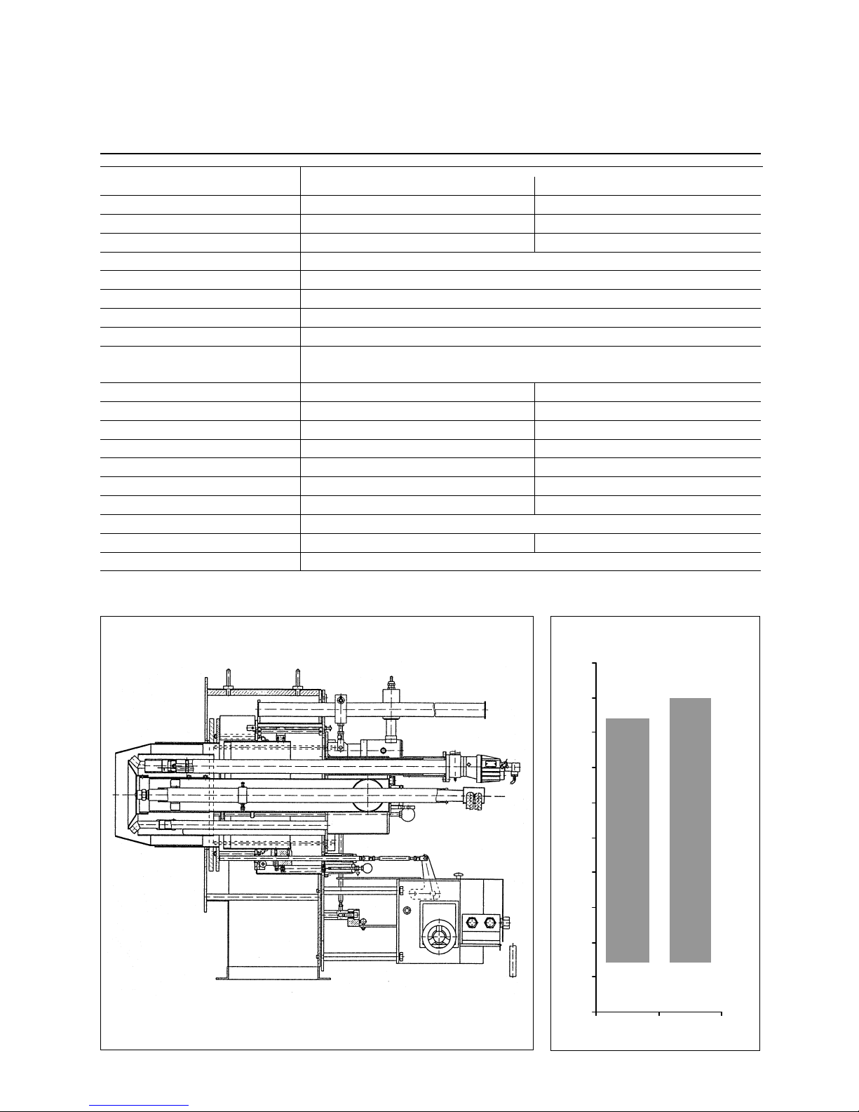
Technical Data Sheet
Duoblock Dual Fuel Burner
Feld52:
RPD 30 / 40 / 50 GL-R / GS -R
6042
8230
1116 0
954
110 0
1400
0
2000
4000
6000
8000
10000
12000
RPD 30 RPD 40 RPD 50
kW
Technical Data
Fuel flow rate (light oil)
Gas flo w rat e
Operating mode
Fuel ty p e
Automatic burner controller
Flame sensor
Ignition burner
Ignition transformer
Pump output at 35 bar
MAT oil control block
Oil connection
Nozzle rod
Nozzle
Actuator
Gas conn ection
We ight
Pre ssure loss i n mixing uni t
Gas contr ol organ
Burner output
Output range
954 - 6042 kW
RPD 30
81 - 513 kg/h
95 - 604 m³/h
fully modulating
Light oil / heavy oil / natura l gas / special fuels
LFL 1., LGK 16 or other approved models
QRA 2, QRA 53 o r other approved models
MAT / Hegwein ZNVL (ZT0)
D-52 L5 KV
Z112 K5
1200 l/h
SRB 19000/30
R 3/4" / 22 mm
MAT / DG 75
MAT - MK 27
WA N 4
R 3"
430 kg
30 mbar or according to diagram
accordi ng to gas pressure
(MAT ignition burner)
(Hegwein ignition burne r)
1100 - 8230 kW
RPD 40
98 - 694 kg/h
110 - 823 m³/h
1850 l/h
SRB 19000/40
R 3/4" / 22 mm
MAT / DG 75
MAT - MK 27
WA N 4
R 3"
450 kg
1400 - 11160 kW
RPD 50
118 - 941 kg/h
140 - 1116 m³/h
2400 l/h
SRB 19000/50
R 3/4" / 22 mm
MAT / DG 75
MAT - MK 27
WA N 4
R 5"
600 kg
Technical Data Sheet
Duoblock Dual Fuel Burner
RPD 30, 40 & 50 GL-R / GS - R
Page 5
5
RPD 30, 40 & 50 GL-R / GS - R
Description
Dimensions
Operating mode
Fully automatic for ced drau ght dual fuel
burner, safety equipment according to
EN 267 and EN 676, especially designed for high turn down ratios.
Electric design
Burner pre-wired and ready to connect. All burner components wired to
the burner terminal rail. Burner control
box supplie d loose for installation in
separate contr ol panel. Separate fitted
oil pump assembly.
Combustion air
Separate combustion air blower with
stable and p ulsation-free characterist ics
also on appli ances with a high flue gas
resistance. The combustion air volume
is divided into a primary and a secon-
dary stream. The flame shape may be
adapted by adjustable twist dampers.
Control systems
oil side: adjustable by means of return
flow system with compound controller
and spill back nozzle.
gas side : fuel throughput controlled by
compound controller with adjustable
cam disc and gas inlet butterfly valve.
air side : by means of compound controller with adjustable cam discs for primary air (air dampers) and secondary
air (air cylinder).
Monitoring system
Flame monitoring by means of flame
sensor and tested burner control box.
Combustion air monitoring achieved
through differential air pressure switch,
resp. speed control switch in cas e of
burner with speed control regulation.
Ignition
Direct electric high voltage ignition,
5000 V, by means of an inbuilt ignition
burner.
G
D2
22,5 °
P
4
P
3
X
P1
P2
Y
Z
B1
T1
444
B2
RPD 20 - 60
H
2
H
3
H
1
D1
H
4
T
2
T
3
V
D7
A1
D2
D
4
D
5
1
0
0
%
D
6
5
0
%
L6 50%
L4 100%
B3 B4 B5W
RPD 70 - 100
D2
Gewinde
Länge K
Stift M
D3
D3
Bohrungen Kesselplatte
B6
22,5 °
B8
15°
15°
L5L1
T
U
R
RPDA1B1B2B3B4B5B6B8D1D2D3D4D5D6D7GH1H2H3H4 K L1L4
30 745 78 19 260 375 70 705 416 830 790 385 371 2 90
323,5
17,5 317 620 373 993 650 30 700 124
40 745 78 19 260 375 70 705 416 830 790 423 409 3 40 367 17,5 442 620 373 993 650 30 700 95
50 950 78 19 315 375 70 760 535 1030 990 470 456 380 410 17,5 370 675 475 1150 740 30 770 110
RPD L5 L6 M P1 P2 P3 P4 R T T1 T2 T3 U V W X Y Z LB C FI F2 F3
30 1350 62 12 580 670 320 410 1265 160 192 491 346
22x1,5
3" 248
4x92 5x126
10-----
40 1425 50 12 580 670 320 410 1265 160 192 491 346
22x1,5
3" 248
4x92 5x126
10-----
50 1620 55 12 740 830 416 506 1743 181 250 530 376
22x1,5
5" 319
3x152 5x156
10-----
set screw M
length K
Details of boiler front plate
Page 6
6
Technical Data Sheet
Duoblock Dual Fuel Burner
Feld52:
RPD 60 / 70 / 80 GL-R / GS -R
145 11
20470
30350
2232
3590
5500
0
5000
10000
15000
20000
25000
30000
35000
RPD 60 RPD 70 RPD 80
kW
Technical Data
Fuel flow rate (light oil)
Gas flo w rat e
Operating mode
Fuel ty p e
Automatic burner controller
Flame sensor
Ignition burner
Ignition transformer
Pump output at 35 bar
MAT oil control block
Oil connection
Nozzle rod
Nozzle
Actuator
Gas conn ection
We ight
Pre ssure loss i n mixing uni t
Gas contr ol organ
Burner output
Output range
2232 - 14511 kW
RPD 60
188 - 1223 kg/h
223 - 1451 m³/h
fully modulating
Light oil / heavy oil / natura l gas / special fuels
LFL 1., LGK 16 or other approved models
QRA 2, QRA 53 o r other approved models
MAT / Hegwein ZNVL (ZT0)
D-52 L5 KV
Z112 K5
3100 l/h
SRB 19000/60
R 3/4" / 22 mm
MAT
MAT - MK 50
WA N 4
R 5"
640 kg
30 mbar or according to diagram
accordi ng to gas pressure
(MAT ignition burner)
(Hegwein ignition burne r)
3590 - 20470 kW
RPD 70
303 - 1726 kg/h
359 - 2047 m³/h
4000 l/h
SRB 19000/70
R 3/4" / 22 mm
MAT
MAT - MK 50
WA N 4 A
R 5"
900 kg
5500 - 30350 kW
RPD 80
465 - 2559 kg/h
550 - 3035 m³/h
6400 l/h
SRB 19000/80
R 1" / 28 mm
MAT
MAT - MK 50
WA N 4 A
R 8"
1200 kg
Technical Data Sheet
Duoblock Dual Fuel Burner
RPD 60, 70 & 80 GL-R / GS - R
Page 7
7
D
4
L6 50%
G
L4 100%
RPD 20 - 60
P1
P2
Y
B1
444
X
Z
T1
B2
P
4
P
3
H
2
D1
H
3
H
4
T
2
T
3
V
D7
A1
D2
D
5
1
0
0
%
D
6
5
0
%
H
1
B3 B4 B5W
15°
D2
D3
15°
B6
D2
Stift M
Gewinde
Länge K
D3
B8
Bohrungen Kesselplatte
22,5 °
22,5 °
RPD 70 - 100
U
L1
R
T
L5
RPDA1B1B2B3B4B5B6B8D1D2D3D4D5D6D7 G H1H2H3H4 K L1L4
60 994 78 19 315 375 70 760 622 1080 1040 520 506 420
455,5
18 312 700 497 1197 825 30 735 125
70 1160 78 19 315 375 75 765 731 1240 1200 640 626 520
565,5
18 469 780 580 1360 900 30 740 170
80 1350 75 19 315 375 75 765 860 1450 1400 740 710 597 646 18 600 820 675 1495 1000 30 700 185
RPD L5 L6 M P1 P2 P3 P4 R T T1 T2 T3 U V W X Y Z LB C FI F2 F3
60 1695 62,5 12 750 840 470 560 1760 181 270 555 401
22x1,5
5" 379
4x129 5x160
10 - - - - -
70 1995 85 12 936 1026 600 690 2010 181 365 610 450
28x1,5
5" 410
5x128 7x140
10 - - - - -
80 2285 92 12 1102 1192 700 790 2320 187 310 707 495
28x1,5
8" 489
6x125 9x128
10 - - - - -
RPD 60, 70 & 80 GL-R / GS-R
Description
Dimensions
Operating mode
Fully automatic for ced drau ght dual fuel
burner, safety equipment according to
EN 267 and EN 676, especially designed for high turn down ratios.
Electric design
Burner pre-wired and ready to connect. All burner components wired to
the burner terminal rail. Burner control
box supplie d loose for installation in
separate contr ol panel. Separate fitted
oil pump assembly.
Combustion air
Separate combustion air blower with
stable and p ulsation-free characterist ics
also on appli ances with a high flue gas
resistance. The combustion air volume
is divided into a primary and a secondary stream. The flame shape may be
adapted by adjustable twist dampers.
Control systems
oil side: adjustable by means of return
flow system with compound controller
and spill back nozzle.
gas side : fuel throughput controlled by
compound controller with adjustable
cam disc and gas inlet butterfly valve.
air side : by means of compound controller with adjustable cam discs for primary air (air dampers) and secondary
air (air cylinder).
Monitoring system
Flame monitoring by means of flame
sensor and tested burner control box.
Combustion air monitoring achieved
through differential air pressure switch,
resp. speed control switch in cas e of
burner with speed control regulation.
Ignition
Direct electric high voltage ignition,
5000 V, by means of an inbuilt ignition
burner.
set screw M
length K
Details of boiler front plate
Page 8
8
Technical Data Sheet
Duoblock Dual Fuel Burner
Feld52:
RPD 90 / 100 GL-R / GS-R
42000
45000
7000 7000
0
5000
10000
15000
20000
25000
30000
35000
40000
45000
50000
RPD 90 RPD 100
kW
Technical Data
Fuel flow rate (light oil)
Gas flow rate
Operating mode
Fuel type
Automatic burner cont roller
Flame sensor
Ignition burner
Ignition transformer
Pump output at 35 bar
MAT oil control block
Oil connection
Nozzle rod
Nozzle
Actuator
Gas connection
Weight
Pressure loss in mixing unit
Gas control organ
Burner output
Output range
7000 - 42000 kW
RPD 90
590 - 3540 kg/h
700 - 4200 m³/h
fully modulating
Light oil / heavy oil / natural gas / special fuels
LFL 1. , LGK 16 or other approved models
QRA 2, QRA 53 or other approved models
MAT / Hegwein ZNVL (ZT0)
D-52 L5 KV
Z112 K5
8900 l/h
SRB 19000/90
R 1" / 28 mm
MAT
MAT - MK 50
WAN 5 A
R 8"
1400 kg
30 mbar or according to diagram
according to gas pressure
(MAT ignition burner)
(Hegwein ignition burner)
7000 - 45000 kW
RPD 100
590 - 3800 kg/h
700 - 4500 m³/h
9500 l/h
SRB 19000/90
R 1"/ 28 mm
MAT
MAT - MK 50
WAN 5 A
R 8"
1450 kg
Technical Data Sheet
Duoblock Dual Fuel Burner
RPD 90 & 100 GL-R / GS-R
Page 9
9
RPD 90 & 100 GL-R / GS-R
Description
Dimensions
Operating mode
Fully automatic for ced drau ght dual fuel
burner, safety equipment according to
EN 267 and EN 676, especially designed for high turn down ratios.
Electric design
Burner pre-wired and ready to connect. All burner components wired to
the burner terminal rail. Burner control
box supplie d loose for installation in
separate contr ol panel. Separate fitted
oil pump assembly.
Combustion air
Separate combustion air blower with
stable and p ulsation-free characterist ics
also on appli ances with a high flue gas
resistance. The combustion air volume
is divided into a primary and a secondary stream. The flame shape may be
adapted by adjustable twist dampers.
Control systems
oil side: adjustable by means of return
flow system with compound controller
and spill back nozzle.
gas side : fuel throughput controlled by
compound controller with adjustable
cam disc and gas inlet butterfly valve.
air side : by means of compound controller with adjustable cam discs for primary air (air dampers) and secondary
air (air cylinder).
Monitoring system
Flame monitoring by means of flame
sensor and tested burner control box.
Combustion air monitoring achieved
through differential air pressure switch,
resp. speed control switch in cas e of
burner with speed control regulation.
Ignition
Direct electric high voltage ignition,
5000 V, by means of an inbuilt ignition
burner.
D
4
L6 50%
G
L4 100%
RPD 20 - 60
P1
P2
Y
B1
444
X
Z
T1
B2
P
4
P
3
H
2
D1
H
3
H
4
T
2
T
3
V
D7
A1
D2
D
5
1
0
0
%
D
6
5
0
%
H
1
B3 B4 B5W
15°
D2
D3
15°
B6
D2
Stift M
Gewinde
Länge K
D3
B8
Bohrungen Kesselplatte
22,5 °
22,5 °
RPD 70 - 100
U
L1
R
T
L5
RPDA1B1B2B3B4B5B6B8D1D2D3D4D5D6D7 G H1H2H3H4 K L1L4
90 1700 75 3 420 375 75 870 890 1800 1750 883 870 675 - 18 810 905 850 1755 1100 30 745 190
100 1700 75 3 420 375 75 870 890 1800 1750 935 922 830 - 18 810 905 850 1755 1100 30 745 190
RPD L5 L6 M P1 P2 P3 P4 R T T1 T2 T3 U V W X Y Z LB C FI F2 F3
90 2585 - 12 1300 1390 742 832 2720 224 310 832 620
28x1,5
8" 494
6x132
10x135
10 - - - - -
100 2585 - 12 1300 1390 742 832 2720 224 310 832 620
28x1,5
8" 494
6x132
10x135
10 - - - - -
set screw M
length K
Details of boiler front plate
Page 10

10
Burner Construction
1 Secondary air pressure switch
2 Ignition gas valve group
4 Inspection glasses
5 Terminal box
6 Gas flow rate control damper
7 Secondary air connection
11 Primary air damper
12 Sleeve
13 Combustion air for ignition burner
14 Flame monitor
15 Gas feed pipes
16 Air guide valve
17 Gas nozzles
18 Nozzle
19 Turbulator
20 Flame tube
21 Burner tube
23 Secondary air control valve
24 Extracting assembly
26 Burner housing
27 Ignition burner
28 Nozzle rod
29 Oil pressure switch
30 Oil flow rate controller
32 Electric actuator
Combustion air connection
The combustion air connecti on (Item 7)
may be mounted at intervals of 45° for
the RPD 30-60 version and 30° for the
RPD 70-90 ver s ion. The burner equipment plate with control block and all valves and instruments will be retained in
the vertical position in any case.
13 2 1 14 19 18 20 21 23 26 24 28 27
12
11
4 17 16 15
5 6 29,30 7 32
Page 11
11
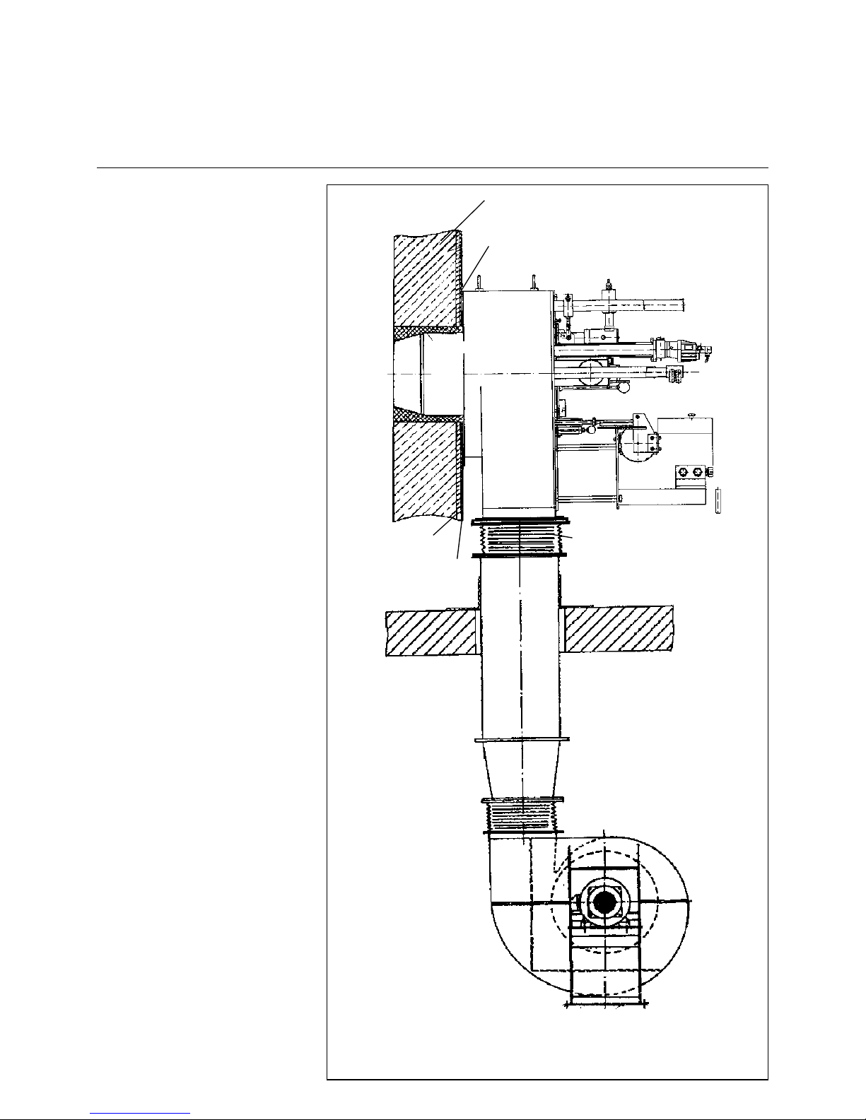
Mounting the Burner to the Boiler
The burner plate of the boiler must be
fabricated to the specified dimensions.
Mount the burner to the boiler with its
insulation backing. Apply a layer to graphite or similar lubri cant to the bo lts and
tighten by equal amounts. Mixing ignition units extended in length are available for boilers requiring a specifi c
installation depth of the burner flame
tube.
Refer to the drawing for the mounting
dimensions of the burner and air duct
and exhaust gas connection, if any.
Boiler lining
The boiler lining must consist of heatresistant materials (temperature resistance >1400°C).
Take care that the burner flame tube is
covered by the boiler lining over its full
lenght.
The space between the burner flame
tube and lining is packed with mineral
wool.
Burner mounting inspection
1. Check the mixing ignition unit
according to the boiler output.
2. Adjust the pilot burner.
3. Refer to the dimensioned drawing
for adjusting the mixing ignitio n
unit.
Boiler lining
Burner flange sealing
Mineral wool
Burner
Insulation
Boiler plate
Mounting bracket
Textile compensator
Air duct
Combustion air fan
Baseframe to anti-vibration mounting
Page 12
12
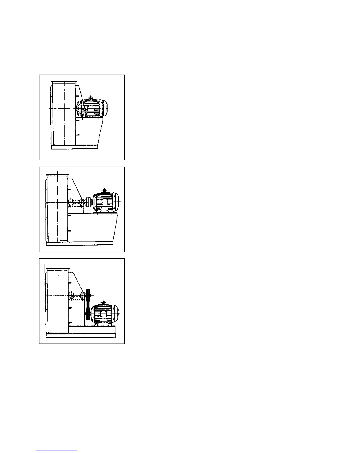
Combustion Air Fan
Drive Modes
1. Direct dr ive
In this concept the motor is coupled
directly to the fan impeller. The fan
impeller is mounted directly on the
motor shaft end. The speeds used are
those of the drive motors only. The bearing of the motor shaft must be specifically designed for the fan impeller used.
Recommendation: up to 10 MW output
2. Drive via flexible coupling
The fan impeller is mounted on its own
shaft by means of a bea rin g sp ec ific al ly
designed for the purpose. The powe r is
transmitted from the drive motor via a
torsionally flexible coupling. The speeds
used are those of the drive motor.
3. V-belt drive
The fan impeller is mounted on its own
shaft by means of a bea rin g sp ec ific al ly
designed for the purpose. The powe r is
transmitted from the drive motor via Vbelts which can provide practically any
desired speed.
Air duct and fan
Baseframe: Pre-mount exactly.
Do not prestress for
mounting.
Direction of rotation: Check for proper
direction of
rotation.
Fans with V-belt drive should be chekked for V-belt tension after about 12
hours of operation and the V-belts
retensioned if necessary. If the V-belts
are not properly tensioned this will
cause slip with resultant lower speed
and a considerably reduced service life.
Mount the air ducts in a way to ensure
an accurate and reliable fixing of the
fan. Connect the air duct by mean s of a
compensator to avoid transmission of
stress. The air ducts are made from 3-4
mm metal sheet.
Page 13
13
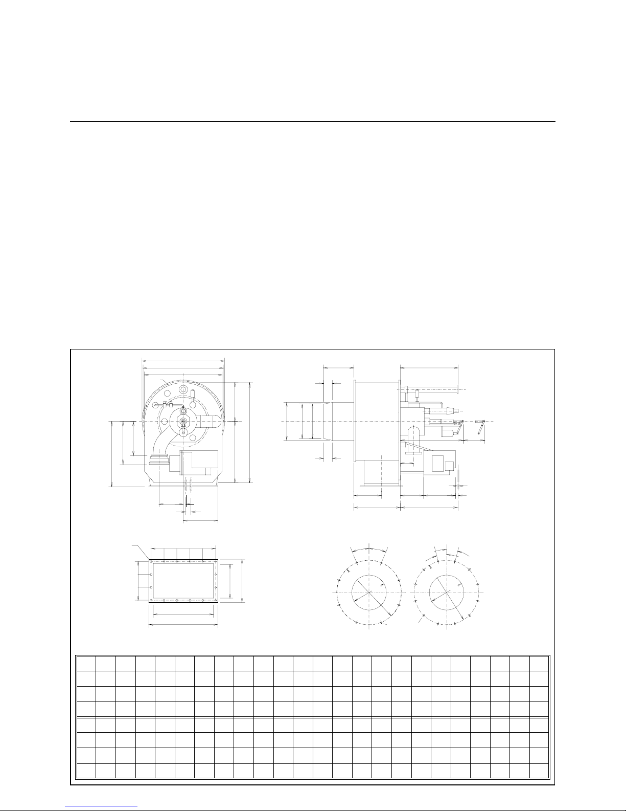
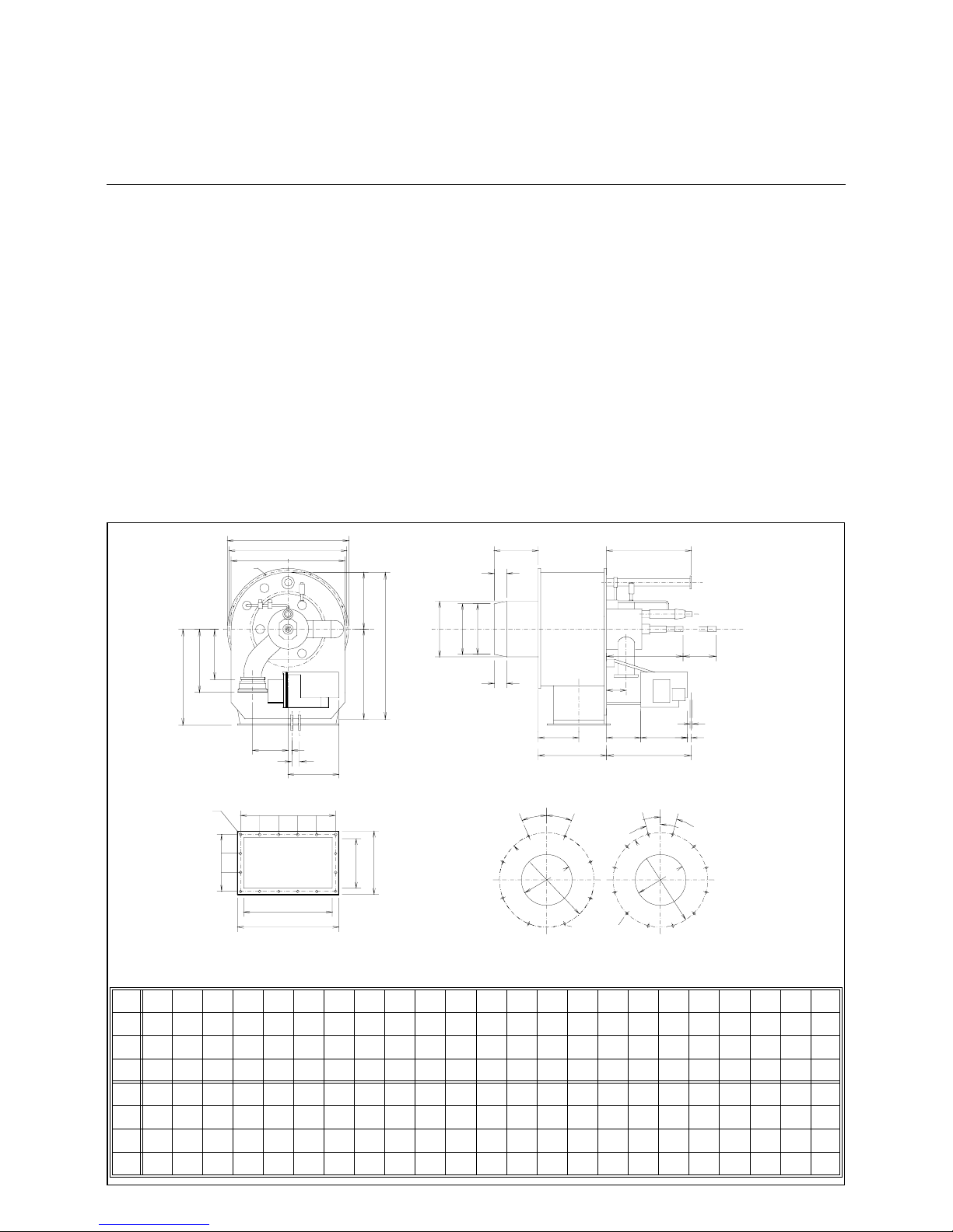
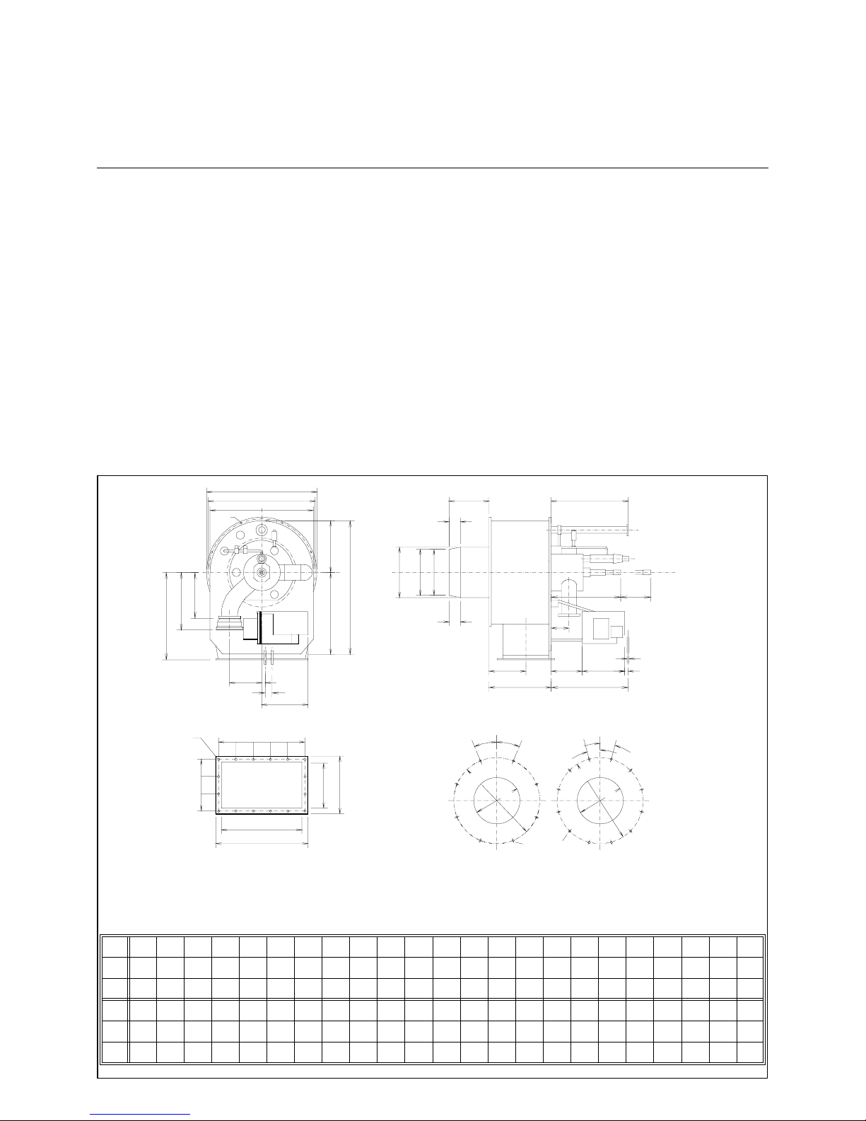
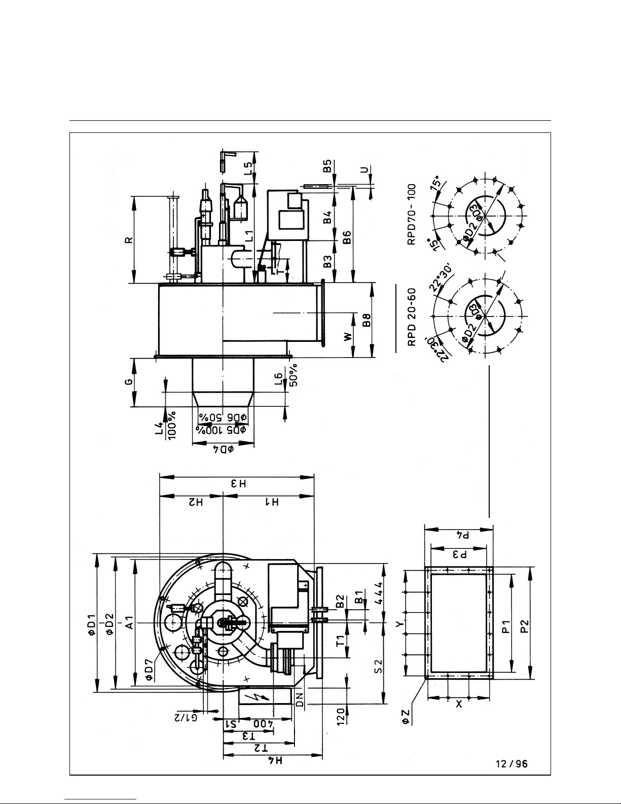
Dimensioned Drawing for RPD Burner 20 - 100
Oil, Gas and Dual-fuel Burners
(without external exhaust gas return)
Boilerplate holes
Set screw M
Lenght K
Attention for burners type U
Mixing unit see on separate
sheet
Page 14

14
Dimensions of RPD Burner 20 - 100
Oil, Gas and Dual-fuel burners
(without external exhaust gas return)
*) Note: If longer flame tubes are used, the extended lenght must be
added to the dimensiones G, R, L5
**) D4 = burner tube outside diameter
***) Flange acc. to DIN 2631 for RPD 20 to 70, and acc. to DIN 2633 for RPD 80, 90 and 100
RPDA1B1B2B3B4B5B6B8D1D2D3D4D5D6D7 G H1H2H3H4 K L1 L4L5
**)
100% 50%
*)
MAT
RDG
1250
10 0% *)
20
530 53 29 90 314 91 560 325 530 500 270 260 210 - 12 250 385 265 650 425 30 465 - 68 780
30
745 78 19 260 375 70 705 416 830 790 385 371 290 323 17,5 317 620 373 993 650 30 550 700 124 1350
40
745 78 19 260 375 70 705 416 830 790 423 409 340 367 17,5 442 620 373 993 650 30 550 700 95 1425
50
950 78 19 315 375 70 760 535 1030 990 470 456 380 410 17,5 370 675 475 1150 740 30 600 770 110 1620
60
994 78 19 315 375 70 760 622 1080 1040 520 506 420 455 18 312 700 497 1197 825 30 650 735 125 1695
70
1160 78 19 315 375 75 765 731 1240 1200 640 626 520 565 18 469 780 580 1360 900 30 740 - 170 1995
80
1350 75 19 315 375 75 765 860 1450 1400 740 710 597 646 18 600 820 675 1495 1000 30 700 - 185 2285
90
1700 75 3 420 375 75 870 890 1800 1750 883 870 675 - 18 810 905 850 1755 1100 30 745 - 190 2585
100
1700 75 3 420 375 75 870 890 1800 1750 945 922 830 - 18 810 905 850 1755 1100 30 745 - 190 2585
RPD L6 M P1 P2 P3 P4 R S1 S2 T T1 T2 T3 U DN W X Y Z
50% *) ***)
20
- 10 430 510 236 316 - - - 112 150 240 -
18x1,5
50 190
2x1 43 4x1 20
10
30
62 12 580 670 320 410 1265 140 497 160 192 491 346
22x1 ,5
80 248
4x92 5x1 26
10
40
50 12 580 670 320 410 1265 140 497 160 192 491 346
22x1 ,5
80 248
4x92 5x1 26
10
50
55 12 740 830 416 506 1743 115 595 181 250 530 376
22x1 ,5
125 319
3x1 52 5x1 56
10
60
62 12 750 840 470 560 1760 195 622 181 270 555 401
22x1 ,5
125 379
4x1 29 5x1 60
10
70
85 12 936 102 6 600 690 2010 270 705 181 365 610 450
28x1 ,5
125 410
5x1 28 7x1 40
10
80
92 12 1102 1192 700 790 2320 310 800 187 310 707 495
28x1 ,5
200 489
6x1 25 9x1 28
10
90
- 12 1300 1390 742 8 32 2720 240 845 224 310 832 620
28x1 ,5
200 494
6x1 32 10x 135
10
100
- 12 1300 1390 742 8 32 2720 240 845 224 310 832 620
28x1 ,5
200 494
6x1 32 10x 135
10
Page 15

15
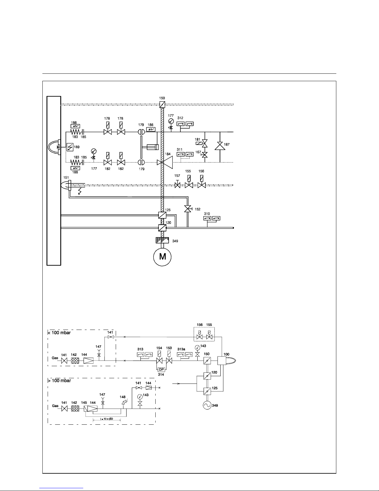
Burner scheme
Gas train
RPD 30, 40 and 50 GL - R / GS - R
TRD 604 - 72 hr :
The 310, 311,312, 313, 313a pressure switches are approved in dual mode or under the
code of "special construction requirements",
the solenoid valve RL (182) in the return line
is required.
TRD 604 - 24 hr :
The 310, 311, 312, 313, 313a pressure switches are designed in single mode. The solenoid valve RL (182) is built in if the return
flow pressure / ring line pressure exeeds 1
bar.
EN :
The 310, 311, 312, 313 pressure switches
are designed in single mode.
The 313a max. pressure switch is not available. The solenoid valve RL (182) is required.
Electrical heating cartridges for the oil bloc,
the nozzle rod and the hoses are used with
heavy oil burner versions only.
Always 1x178 und 1x182 electrical connected
in-line
100 Burner
120 Secondary air cylinder
125 Primary air damper
141 Ball valve
142 Gas filter
143 Pressure gauge with manual valve
144 Pressure governor
145 Safety shutt-off valve
147 Test burner w. push button valve
148 Safety blow off valve
150 Gas butterfly valve
151 Ignition burner lance
152 Air regulating valve
153 Main gas solenoid valve
154 Safety shutt-off solenoid valve
155 Ignition gas solenoid valve
156 Ignition gas solenoid valve
157 Gas regulating valve
167 Ball valve
177 Pressure gauge with manual valve
178 Oil solenoid valve, feed line(115 V)
179 Hydraulic shut-off valve
180 Nozzle assembly with shut-off valve
181 Solenoid valve, oil circulation
182 Solenoid valve, return line (115 V)
183 Oil hoses
184 Pressure regulator return line
185 Coupling
186 Electrical cartridge heater, oil bloc
187 Pressure regulator feed line
188 Trace heating, oil hoses
189 Trace heating, nozzle rod
310 Air pressure switch
311 Oil pressure switch, return line
312 Oil pressure switch, feed line
313 Gas pressure switch, low
313a Gas pressure switch, high
314 Gas leakage control
349 Mechanical compound controller
Burner scheme TRD 604 - 72 h
gas
oil feed line
ignition electrodes
oil return line
air
primary air
secondary air
ignition gas
Gas train TRD 604 - 72 h
air
secondary
primary
Page 16
16
Burner scheme
Gas train
RPD 60 - 100 GL - R / GS - R
TRD 604 - 72 hr :
The 310, 311,312, 313, 313a pressure switches are approved in dual mode or under the
code of "special construction requirements",
the second solenoid valve RL (182) in the
return line is required.
TRD 604 - 24 hr :
The 310, 311, 312, 313, 313a pressure switches are designed in single mode. The
second solenoid valve RL (182) is built in if
the return flow pressure / ring line pressure
exeeds 1 bar.
EN :
The 310, 311, 312, 313 pressure switches
are designed in single mode. The 313a max.
pressure switch is not available. Both solenoid valves RL (182) are required.
Electrical heating cartridges for the oil bloc,
the nozzle rod and the hoses are used with
heavy oil burner versions only.
Always 1x178 und 1x182 electrical connected
in-line
100 Burner
120 Secondary air cylinder
125 Primary air damper
141 Ball valve
142 Gas filter
143 Pressure gauge with manual valve
144 Pressure governor
145 Safety shutt-off valve
147 Test burner w. push button valve
148 Safety blow off valve
150 Gas butterfly valve
151 Ignition burner lance
152 Air regulating valve
153 Main gas solenoid valve
154 Safety shutt-off solenoid valve
155 Ignition gas solenoid valve
156 Ignition gas solenoid valve
157 Gas regulating valve
167 Ball valve
177 Pressure gauge with manual valve
178 Oil solenoid valve, feed line (115 V)
179 Hydraulic shut-off valve
181 Solenoid valve, oil circulation
182 Solenoid valve, return line (115 V9
183 Oil hoses
184 Pressure regulator return line
185 Coupling
186 Electrical cartridge heater, oil bloc
187 Pressure regulator feed line
188 Trace heating, oil hoses
189 Trace heating, nozzle rod
310 Air pressure switch
311 Oil pressure switch, return line
312 Oil pressure switch, feed line
313 Gas pressure switch, low
313a Gas pressure switch, high
314 Gas leakage control
349 Mechanical compound controller
Burner scheme TRD 604 - 72 h
gas
oil feed line
ignition electrodes
oil return line
air
primary air
secondary air
ignition gas
Gas train TRD 604 - 72 h
air
secondary
primary
Page 17
17
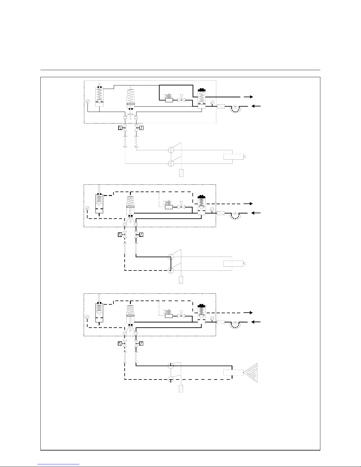
Hydraulic Scheme
RPD 30 -50
Oil Control Block and Nozzle Rod DG 75
11
12
12
14
14
16
16
13
15
8
10
9
7
6
5
4
3
2
1
11
12
12
14
14
16
16
13
15
8
10
9
7
6
5
4
3
2
1
11
12
12
14
14
16
16
13
15
8
10
9
7
6
5
4
3
2
1
Oil circuit at burner stand by
(Zirkulation)
Oil circuit at burner pre-purge
Oil circuit at burner operation
1. Oil pressure pump
2. Safety valve
3. Oil filter
4. Pressure gauge (feed line)
5. Oil regulating valve
6. Manual valve (for bleeding)
7. Circulating valve
9. Hydraulic cylinder for ball valves
10. Oil regulating valve, return line
11. Pressure gauge (return line)
12. Ball valve
13. Inner nozzle oil line assembly
14. Solenoid valves
15. Return nozzle
16. Pressure hoses
Page 18
18
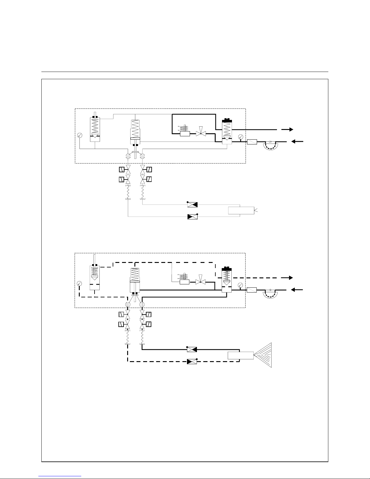
Hydraulic Scheme
RPD 30 -100
Oil Control Block and Nozzle Rod MAT
11
12
12
14
14
14
14
16
16
15
17
17
17
17
13
10
9
7
6
5
4
3
2
1
11
12
12
10
9
7
6
5
4
3
2
1
14
14
14
14
1616
15
13
Oil circuit at burner stand by
(Zirkulation)
Oil circuit at burner operation
1. Oil pressure pump
2. Safety valve
3. Oil filter
4. Pressure gauge (feed line)
5. Oil regulating valve
6. Manual valve (for bleeding)
7. Circulating valve
9. Hydraulic cylinder for ball valves
10. Oil regulating valve, return line
11. Pressure gauge (return line)
12. Ball valve
13. Inner nozzle oil line assembly
14. Solenoid valves
15. Return nozzle
16. Pressure hoses
17. Non-return valves
Page 19
19
1. oil solenoid valve circulation
2. oil regulating valve return flow
3. oil regulating valve bloc inlet pressure
4. regulating needle
5. spring
6. washer
7. shaft
8. surclip
9. O- ring seal N. 19
10. bush gland
11. gasket
12. washer
13. surclip
14. spring
15. washer
16. surclip
17. regulating needle
18. spring
19. washer
20. shaft
21. gasket
22. bush gland
29. shaft
30. piston
31. gasket
32. lock washer
33. nut M8
34. spring
35. spring cover
36. cover plate
37. aluminum washer
38. valve flange
39. double blocking valve
40. outer shaft ring
41. washer
42. fixing ring
43. valve cover
44. O ring gasket
45. cover
46. block body
47. nut M8
Oil Control Block
Page 20
20
Mounting Position
Leak Test
Ignition Gas Connection
Ignition Burner Type ZT0
Mounting position
Gas pressure regulator s and valves can
be mounted in vertical lines in any position within the 360° range. In horizontal
lines they must not be mounted overhead and only 180° in the upper se cto r.
The ball valve and filter can be mou nted
in any desired position. Take care that
the housing does not m ake c ont act w ith
the wall and is clear by minimum 20
mm. Do not use the spring bolt of the
regulator and the solenoid elements of
the valves as levers.
Leak test
Check the screwed joints and flanged
connections for absence of leaks. The
leak test of the joints should be made
under pressure using only foaming
agents approved by DVGW and not
causing corrosion.
Electrical wiring of gas valves
Check that the data given on the nameplate of the gas valves agree with the
mains voltage.
Open the terminal box of the valve.
Feed the connection cable through the
screwed union (condui t thr ead Pg 13 .5)
and connect the terminals marked
accordingly.
L = phase
N = zero conductor
= protective conductor
(green-yellow)
Disconnectable joint
An easy-to-disconnect joint with flat
sealing (e.g. compensator) should be
provided to allow the boiler door to be
swivelled out if required for maintenance work on the boiler (furnace
chamber). Th is compensator should
also be designed to accommodate the
axial or lateral expansion and absorb
vibrations.
Ignition gas connection
An ignition burner is used to ignite the
main gas flame. The ignition gas line is
branched out of the gas control group
between the two gas valves and installed to the ignit ion bu rner on the s hortes t
possible way. In the case of oil and
dual-fuel burners the burner is ignited
with propane supplied through a separate R „ propane connection. The ignition gas flow rate may be adjusted on
the volumetric flow control valve of the
ignition gas valve or directl y on the ign ition gas burner. The required gas pressure for the ignition gas burner is 50150 mbar . It is ad vis ab le to ins t all a gas
pressure regulator upstream of the ignition gas burner . Th e air pres sure for the
ignition gas burner should be between
10 and 30 mbar. The boi ler back pressure shall not be taken into account.
The air pressure should be adjusted in
accordance with the gas pressure to
ensure an undelayed ignition and a
good flame pat tern.
1 Transformer unit with bui lt-i n
ignition transformer
2 Electrical angular plug connector
3 Gas connection, may be
connected on either side right and
left with gas test socket
4 Air connection, mounted to
transformer unit
5 Air test socket
6 Igniter tube, mounted to air flange
7Spacer ring
8 Ignition electrode connection rods
9 Gas tube
10 Ignition electrode connection rods
11 Gas nozzle for natural gas or
propane
12 Mixing chamber
* The outside diameter will be 50 mm for
tube lengths above 4000 mm and for all
high-grade steel tubes.
Mounting f lange
View A
Gas RP1/2
normally left
Air Rp1
Ignition Burner Type ZT0
Page 21

21
Ignition Burner Type ZT0
Technical Data
Construction according to sectional
drawing
The igniter consists mainly of the transformer unit (Item 1) housing the ignition
transformer , the ignit er tube with a ir and
mounting flange (Item 6 ), a gas tub e (9)
with nozzle (11) and the electrode carrier ring (10). The igniter tube with the
Rp1 air connection is bolted to the
transformer unit. After the 4 bolts (Item
4) have been unscrewed it may be
removed or turned by 90° if required by
the position of the air connection. When
turning the tubes care must be taken
not to change the position of the inner
supporting rings and rods because this
might lead to operational trouble.
The gas supply may be connected either to the left-hand or right-hand opening. The opening not used is closed
with a screw plug which al so car ries the
screw-in gas test socket (3). The electrode support ring (Item 10) is mounted
to the end of the gas tube.
The ionization electrode and ignition
electrode are extended with conn ec tin g
rods (Item 8). These rods are installed
through the bottom of the transformer
housing in 2 ceramic insulators and carried by intermediate supporting rings
(Item 7) spaced at 300 mm.
Flame moni tor
An ionization electrode is provided for
flame monitoring. The flame signal is
generated by d.c. current which due to
the ionization effect and the rectifier
effect of the flame is caused to flow from
the igniter tube earth via the flame to
the ionization electrode and via the connecting rod to the amplifier in the automatic furnace controller. The ionization
electrode and ignition electro des ar e
adjusted in accordance with the dra wing.
When installing new electrodes these
must be bent, cut to len gth and adjusted
as required.
The internal resistance of the ionization
system amounts to some megohms.
Such a high resistance ensures a good
insulating capacity of the electrodes and
connecting rods. In a dust-laden combustion air environment it is therefore
important to clean t he ins ulators a t shorter intervals. Humidity should be kept
out. See also electrical function.
The ceramic insulator of the ionization
electrode must not be allowed to heat
up above 500 °C because this could
lead to shutdown on tro ubl e. Therefore,
a minimum air flow rate (10-20 % of the
full-load rate) should be allowed to flow
if this temperature is likely to be reached by radiation or convection with the
furnace chamber in hot condition and
the burner flame turned off.
Technical data of ignition gas burner type ZT0
Fuel gases according to G 260
Flame power max. 120 kW
Flame length max. 600 mm
Gas connection Rp 1/2 right or left
Air connection Rp 1, may be turned by 4x90°
Air flow rate max. 50 m³/h
Air index 0.3-0.5; remaining air rate must be available from furnace chamber
Max. ambient
temperature 500°C in tube; if temperature is higher, keep combustion air
connected partly as cooling air; 0°C to +60°C in transformer unit
Transformer unit
Connection voltage 230 V, 50 Hz
Connector type plug connector
Power input ignition transformer 100 VA, 20% duty cycle (with thermal winding shield)
ignition 5 kV (2-3 seconds via automatic furnace controller)
Ambient temperature 0°C to +60°C
Degree of protection IP 54
Electrical connection
Cl. 1 (Mp)
Cl. 8 (Ph) ignition transfer, primary Use shielded cable Z 912 F 00 for flame feedback.
Cl. 10 ionization signal NOTE: The shield must not make contact with earth.
Page 22
22
Ignition Burner Type ZT0
Gas Pressure Adjustment
Parts List
Gas pressure adjustment
In standard version the igniters are suitable for a working range 50-150 mbar.
If a higher gas pressure is required in
the customer's order, the two threaded
gas inlet connections will be fitted with
restrictors by the manufacturer already.
The igniter will in this way be adjusted
to the pressure above 150 mbar.
If the higher inlet pressu re is recogniz ed
at a later stage only, a restriction to
maximum 150 mbar can also be achieved by means of a ball valve, for
example.
Characteristic
line Gas type Nozzle holes Flame length
P Propane 1x2,5 + 6x1,0 approx. 600 mm
M Natural gas 1x4,0 + 6x1,3 approx. 500 mm
N City gas 1x5,0 + 8x2,3 approx. 500 mm
Parts list
Item. Qty. Description Part No. Material
1 1 Transformer unit Z 112 K 5 Housing of GAL
2 1 Right-angle plug with 2 unions A 5 Z 1 10-pole, max. 2.5
3 1 Gas test socket Z 138 Z 2 Ms 58
4 4 Hexagon socket head screw W 826 F 10
5 1 Air test socket Z 138 Z 1 Ms 58
6 1 Igniter tube with rolled-in mixing chamber and mounting
flange with Rp1 air inlet thread
Z 1050 Z...** GAL / steel
7 * Intermediate supporting ring with 2 ceramic insulators Z
545 F11
Z 960 K 4 St VII 23
8 2 Connecting rods Z 781 F...** Zinc-plated steel
9 1 Gas tube Z 521 F...** St 35
10 1 Electrode carrier ring Z 960 K 13 St VII 23
11 1 Gas nozzle Natural gas
Propane
City gas
Z 330 F 4013
Z 330 F 2510
Z 985 F 1
High-grade steel 1. 4104
High-grade steel 1. 4104
High-grade steel 1. 4104
12 - Mixing chamber with mixing ring Included in
Item 6
High-grade steel,
heat-resistant
* Quantity depends on pipe length: 3 intermediate rings per metre of tube length.
** Additional data according to type (tube length).
Page 23
23
Ignition Burner Settings
Electrode Carrier Ring
Front
view
Side view
110 mm for natural gas
90 mm for propane
Top view
Natural gas
Propane
Electrodes Z 707 F 3
Ceramic Z 545 F 11
Ring W 715F 101
Bush Z 789F 10
Preset amount of bend and adjustment
Cut ionization electrode to length according to gas type.
Page 24
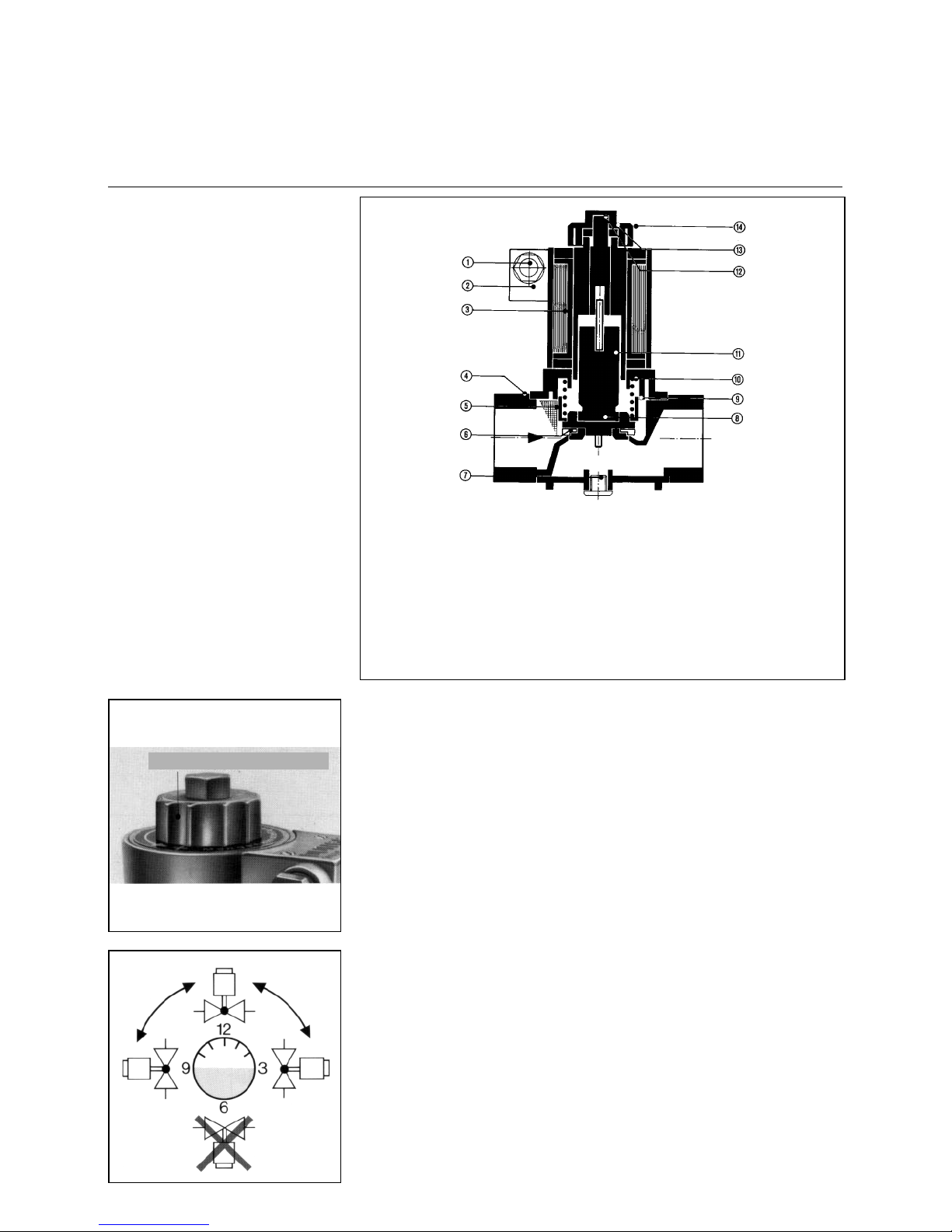
24
Ignition Gas Solenoid Valve
Type MVD 505 / 5 single-stage
Technical data:
Nominal bore: R1/2“
Max. operating
pressure: 500 mbar
Opening time: < 1 sec
Closing time : < 1 sec
Ambient temperature:-15°C to +60°C
Mounting position: solenoid in upright
position vertical to
horizontal
Voltage/frequency: (AC) 230 V
(+10% -15%)
Duty factor: 100% CD
Degree of protection: IP 54, IP 65
Power rating: 15 VA
Main flow rate adjuster
type series MVD
Unscrew the prot ective cap a nd remove
the lock nut to allow the main flow rate
to be adjusted. The main flow rate adjuster is supplied ex works in fully opened
position.
Turning clockwise will reduce the gas
flow rate.
Turning counterclockwise will increase
the gas flow rate.
After having adjusted the flame control
on the gas burner make sure to tighten
the lock nut again. Screw on the protective cap again.
Installation
When installing the valve in the pipeline
take care to observe the arrow on the
valve housing and the required mounting position. For screwing the pipeline
into the valve housing do not use the
magnet as a lever but apply a suitable
tool against the valve housing.
After installati on ma ke a test for
absence of leaks and proper operation.
Solenoid replacement
type series MV, MVD
Disconnect the electrical termina ls ;
remove the screw cap; lift off the solenoid. For install ation proc eed in reve rse
order.
Electrical connection
Feed in the cable through cable union
(conduit thread Pg 11). Make the electrical connection by me ans of the screw
terminals in the termi nal bo x of the sole noid housing.
Take care to observe the connection
diagram.
1 Cable union
2 Electric terminal box
3 Solenoid
4Housing
5Screen
6 Valve seat
7 Connector for
earthing contact K01/1
8 Valve disk
9 Mud guard
10 Closing compression spring
11 Anchor
12 Main flow rate adjuster
13 Lock nut
14 Protective cap
Protective cap
Not
acceptable
Page 25

25
Oil Connection
Fuel Oil Supply
Oil connection
For the installation of a furnace system
care should be taken to observe the
applicable rules and regulations. When
installing an oil burner be sure to follow
the recommendations outlined for oilfired furnace systems (DIN 4787,
DIN 51603 Parts 1&2, TRD 411). DIN
4736 Parts 1 &2 describes the safety
requirements applicable to the oil supply systems of oil burners. DIN 4755
Part "Oil furnaces in heating installations (safety requirements)" outlines the
safety recommendations for oil furn ac e
systems of steam boilers.
The installer has the duty to inform
himself of the regulations applic able to
gas and oil furnace systems.
Fuel oil supply
Complete oil feeding groups are
available for the supply of the furnace systems with fuel oil. A fuel oil
supply unit may consist of ball stop
valve, suction filter , pressure gauge,
pump with coupling and threephase rnotor. All units are all finished ready for connection and
mounted with anti-vibration elements on an oil collecting tray.
The oil supply lines must be slelected in accordance with the technical
instruction sheets and installed in
line with the applicable specifications. The total pipeline length is
understood to be the length of all
horizontal and vertical lines and
bends. The maximum permissible
vacuum at the suction port of the
pump may be -0.6 bar. A higher
vacuum will lead to the escaps of
gas resulting in an unsteady delivery and damage to the pump.
All connections must be tightened
to avoid leaks. The sealing rings
used should be of copper, aluminium or plastic. In no case should
hemp or similar sealing material be
used. The pipelines must be cleaned before they are connected to
the pump.
Ring line operation
lf several burners and storage t anks are
installed in a system o r if t here is a large
distance between the burner and the
storage tank, a ring line system with
gas-air separater will be needed for
supplying the burners.
NOTE: In case of pressurized oil feed,
the suction press ure of the p ump shoul d
not exceed 5 bar. All lines must be
fixedly installe d, welded to oil-tight s tandards or connected with oil-tight unions
or flanges.
Flexible tubes are allowed only as connecting pieces between the fixed line
and the burner . The flexi ble tubes
should be installed properly (in hanging
position) and free of sharp bends.
For the installation of the flexible
tubes take care these do not get
twisted. They should not be subject
to torsional stress neither at the
stage of installation nor during subsequent movernents.
Oil pressure pump filling
Prior to initial oparation make sure to fill
the oil pressure pump and oil feed line
with oil to prevent the pump from dry
running and getting seized.
Oil filter
lt is recommended to install a filter
directly upstream of the pump to separate dirt particles contained in the oil or
any other foreign matter produced
during installat ion. When a fuel oil uni t is
mounted this will be fitted with an oil filter already.
Starting the oil pump
- Make sure all stop valves are
open.
- Check the pump for direction of
rotation.
- The safety overflow valve in the
pump is preset at 40 bar and may
be readjusted by duly authorized
specialists only.
Pressure atomizer
The oil throughput rate of the nozzle
and thus the burner output is controlled
by an oil regulator valve installed in the
return line and coupled to the actuator
and compound controller.
The oil throughput rates and oil flow
pressures downstre am of the nozzle ro d
must be set according to the applicable
nozzle characteristic.
As the oil control valve is closed or opened the oil through put rate of th e n ozzle
will be increased or reduced, respectively.
The oil pressure up stre am of th e nozz le
rod must be set at 28 bar to 30 bar.
Depending on the version this can be
can be adjusted either on the fuel oil
station or on the oil control block of the
burner.
Page 26

26
Oil Connection
Fuel Oil Supply
Oil connection
For the installation of a furnace system
care should be taken to observe the
applicable rules and regulations. When
installing an oil burner be sure to follow
the recommendations outlined for oilfired furnace systems (DIN 4787,
DIN 51603 Parts 1&2, TRD 411). DIN
4736 Parts 1&2 describes the safety
requirements applicable to the oil supply systems of oil burners. DIN 4755
Part „Oil furnaces in heating installations (safety requirements)“ outlines the
safety recommendations for oil furn ac e
systems of steam boilers.
The installer has the duty to inform
himself of the regulations applic able to
gas and oil furnace systems.
Fuel oil supply
The operational reliability of a burner
system depends greatly on the oil supply conditions.
Oil supply lines must be determined
according to the technical instruction
sheets and inst a lled b y strict adhe rence
to the applicable regulations.
All joints must be mounted with due
care to ensure they are absolute ly tight.
The sealing rings used must be made
from copper, aluminium or plastic. In no
case should hemp or a similar material
be used. Make sure to remove any dirt
from the pipelines before mounti ng
them to the pump.
Normally, a ring pipe system will be
used.
In addition to the electri c tracing l ines, a
ring pipe system for heavy oil installations comprises the following major components:
oil delivery pump,
oil filter ,
gas-air vent, and
pressure control valves.
The electric tracing lines and the tank
heaters will ensure that th e fuel oil to be
delivered is kept in a pumpable state.
An oil filter must be installed in the feed
line upstream of each burner to avoid
that dirt particles and other impurities
possibly left behind after pipe installation cannot damage the solenoid and
pressure control valves.
Steam trac ing or hot-wa ter trac ing
systems can be used instead of the
electric tracing lines.
T o av oid burner troub le due to entrain ed
air, a gas-air vent must be provided at
the uppermost position of the ring pipe
system.
The ring pipe pressure must be controlled in dependence of the fuel oil temperature.
As can be seen from the chart below,
the static pressure of the oil at 130°C
must be minimum 3 bar, for example.
Oil pressure in dependence of
operating temperature
The fuel oil withdrawn from the ring pipe
or gas-air vent is pumped to an oil preheater and on to the b urner by means of
a high-pressure pump. The return oil
from the burner is fed into the ring pipe
in any case and not directly into the
tank.
Oil pressure pump filling
Prior to initial operation make sure to fill
the oil pressure pump and oil feed line
with oil to prevent the pump from dry
running and getting seized.
Oil filter
It is recommended to install a filter
directly upstream of the pump to separate dirt particles contained in the oil or
any other foreign matter produced
during installat ion. When a fuel oil uni t is
mounted this will be fitted with an oil filter already.
Starting the oil pump
- Make sure all stop valves are
open.
- Check the pump for direction of
rotation.
- The safety overflow valve in the
pump is preset at 40 bar and may
be readjusted by duly authorized
specialists only.
Pressure atomizer
The oil throughput rate of the nozzle
and thus the burner output is controlled
by an oil regulator valve installed in the
return line and coupled to the actuator.
The oil throughput rates and oil flow
pressures downstre am of the nozzle ro d
must be set according to the applicable
nozzle characteristic.
As the oil control valve is closed or opened the oil through put rate of th e n ozzle
will be increased or reduced, respectively.
The oil pressure up stre am of th e nozz le
rod must be set at 28 bar to 30 bar.
Depending on the version this can be
can be adjusted either on the fuel oil
station or on the oil control block of the
burner.
0
1
2
3
4
5
100 110 120 130 140 150 160
Temperatur °C
Druck bar
Temperature °C
Pressure bar
Page 27

27
Medium pressure screw pumps
Installation
Commissioning
Maintenance
Medium pressure screw pumps
General
Screw pumps are rotating positive displacement pumps with strong suction,
which can be used with self-lubricating
agents.
1. Application guidelines
1.1 Shaft seals for normal versions
1.2 Pressure relief valve
This valve protects the pump against
overloading and should not be used as
a pressure control valve. This is absolutely necessary if a shut-off device is fitted in the pressure pipe. Standard
pressure setting unless otherwise required at the time of ordering. Low pressure pumps (type N) approx. 6 bar,
medium pressure pumps (type M)
approx. 40 bar or 10% above the specified operating pressure, as with Ctypes. By turning the adjustment sc rew
in a clockwise direction = pressure
increase.
2. Installation
2.1
Clean any plant parts (ensure no dirt or
loose particles in the pipes) and fi t pipes
(flange) without any stress. Observe
direction of flow as well as any possible
heat expansion of the pipes.
2.2
Ensure stress-free fitti ng of th e pump or
base frame.
2.3 Coupling
Motor and pump shafts must be aligned. Axial play between the Coupling
halves approx. 1.5 mm. It should be
possible to turn the whole unit of pump
shaft-Coupling-Motor shaft by hand.
Installation of the coupling halves: Sliding on (tapping not permitted) in heated condition (min. 100°C); Press p lastic
couplings home in cold condition.
2.4
Check direction of rotation of the motor
and the pumps a nd pro tect the moto r by
means of a motor protection switch.
3. Commissioning
3.1
The pump must not be allowed to run
dry!
Before initial commissioning of the
pump fill the pump with operating
medium and open suction and shut-off
devices on the pressure side. The
medium must be free from solids.
3.2
With hot medium (above 100°C) heat
the pump before s t art ing (pump heating
facility). ATTENTION! The medium in
the pump and pipes must be able to
expand freely during heating (development of unauthorized pressures with
enclosed medium).
3.3
Viscous mediu m, whic h can only be
pumped after heating, must be heated
first in the pump and pipes (pump heating as well as secondary heating for
pipes). ATTENTION! Heat expansion of
the medium (see above).
When pumping heavy heating oil it is
essential that cold starting of the pump
is avoided (use pu mp heating prov ided),
as this could also damage the shaft
seal.
3.4
Vent the pressure pipe during initial
starting of the pump.
3.5
Switching off the pump: Residual static
pressure in the pressure pipe must no
exceed that of the permissible supply
pressure. If necessary, de-pressurize
the pump through the non-return valve,
as this pressure pressurizes the shaft
seal which in turn could damage the
seal. The same applies to parallel operation of several pumps.
4. Maintenance
Special maintenance of the screw
pumps is not required. In case of
damage to the pump of the inst allation it
is possible that medium will leak out. In
order to avoid subsequent damage it is
recommended that respective warning
devices are fitted.
Type of seal Max. supply
pressure
Max.
Temperature
Rotary shaft 0,5 bar 80°C
Packing rings 3 bar 150°C
Axial face seal 5 bar 150°C
Page 28
28
Medium pressure screw pumps
Technical specifications
Function
Versions
Technical specifications
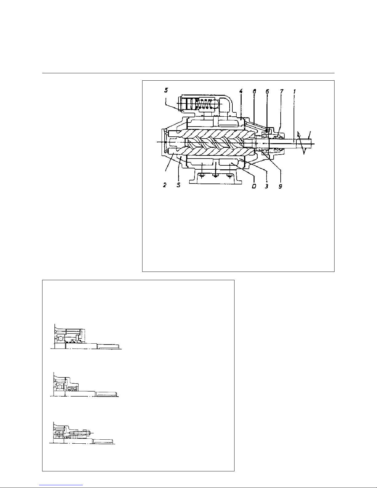
Function
Screw pumps have three rotating spindles, of which the main spindle supplies
the hydraulic power and the auxiliary
spindles, which run free, have only a
rotating function. The two-speed main
and auxiliary spindles crea te sup pl y
chambers within the enclosed housing,
which move constantly from the suction
to the pressure side. Due to this principle the screw pump s ca n also o perate
under high pressures, revolutions and
provide strong suction, they are extremely quiet and almost pulse-free.
Safety valve
All types of medium pressure pumps
can be supplied on request with or without a spring-loaded pressure control
valve. The valve is installed to protect
the pump and/or installation against
excess pressure, but cannot be used
solely as a control valve.
Materials
Supply spindles Nitrided steel
Housing Grey cast iron
(M55 to M210) Nodular graphite
iron
Operating housing Al-Si alloy *
Cover plate Al-Si alloy *
* Guarantees the best emergency
running characteristics and long
service life
Flow rate Approx. 3 - 420 l/min
Operating pressure Max. 40 bar
Supply pressure See under versions
Operating temp. See under versions
Viscosity 1.0 E (6 cSt) to
100 E (758 cSt)
and greater
Direction of rotation Right, viewed from
drive
Heating Supplied on request
1. Main spindle
2. Auxiliary spindle
3. Enclosed housing
4. Pump housing
5. Safety valve (adjust a ble )
6. Main spindle bearing
7. Seal
8. Compensating bore
9. Compensating piston
S Suction chamber
D Pressure chamber
The axial forces acting on the feed
screws are balanced (compensated)
by the compensating piston (9) and
compensating bores (8).
Versions
Medium pressure sc rew pump s, as shown on the follo wing p ages, a re suppli ed in
various constructions. Depending on the application, the following types of seal
are available:
Rotary shaft sealing ri ngs
Normal packing and rotary shaft seal
Temperature: Max. 150 °C (above
150°C on request)
Supply pressure: Max. 5 bar (above 5
bar on request)
Temperature: Max. 80°C
Supply pressure: Max. 0.5 bar
Temperature: Max. 80°C
Supply pressure: Max. 0.5 bar
Axial face seal
Page 29

29
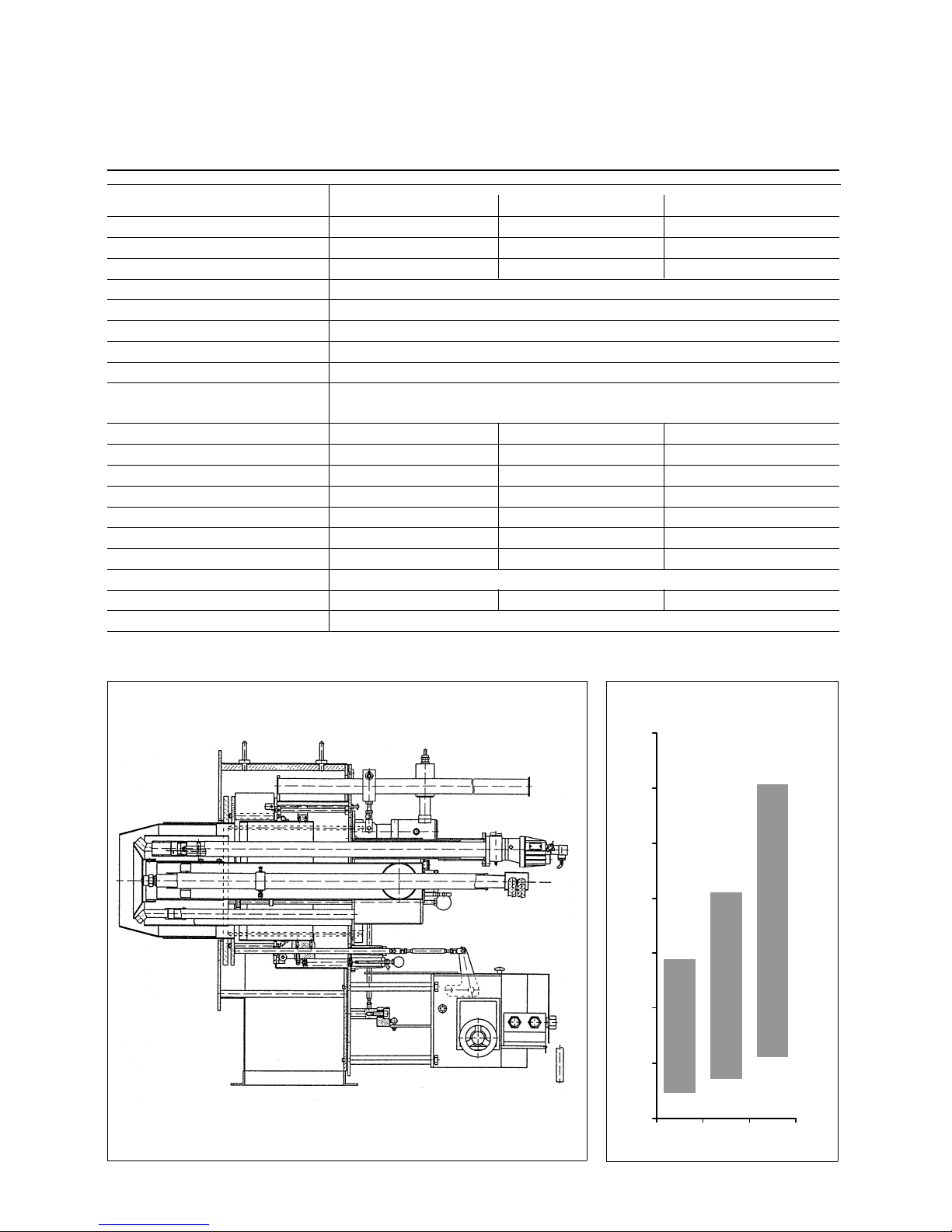
Burner Pump Assembly
Electrical Connection
Burner pump assembly
The installation material and all electrical connections and earthing points
must be in accordance with the
VDE 0116 specifications and the local
regulations. The electrica l connection o f
the burner must be made as shown in
the circuit diagram att ached hereto. The
electrical control lines are installed
through the screwed cable joints and
connected to the numbered terminal
strip in accordance with the circuit diagram. Control boxes related to the burner must also be connected in
accordance with the enclosed circuit
diagram and VDE 0116 and taking into
account the local regulations. After the
electrical connections have been completed a check must be made for the
correct wiring of all items of the equipment.
Also the direction of rotation of the air
fan and of the pump should be checke d.
1 Electrical terminal box
2 Plug connector
3Terminal strip
4 Cable bushings
Electrical connection
1Stop valve
2 Pressure/vacuum gauge
3 Ball valve
4 Oil pressure pump
(volumetric)
5Drip tray
6 Oil filter
7 Ball valve
8 Flange connection
9 Pump bracket
10 Pump-end coupling
11 Motor-end coupling
12 Electric motor
Page 30

30
Return Nozzle Rod DG 75
Functional description
Pre-flushing
The oil delivered by the burner pump
will enter the feed pipe (Item 2) via the
connection block (Item 1). Then it flows
through the feed pipe to the closing
taper plug of the regulating piston (Item
4). The plug is permanently pressed
against the nozzle head (Item 7) by a
cylindrical pressure spring (Item 5) so
that the feed pipe is kept in closed position. At the same time, pressure is applied to the connecting rod (Item 8) by a
spring (Item 6) so that the valve needle
(Item 12) is pressed against the return
opening of the nozzle head (Item 7),
thus keeping the latter in closed position.
In this position the oi l may only enter the
return pipe (Item 9) through the o pened
flushing hole (Item 13 ) an d wi ll return to
the gas-air separator and finally to the
fuel tank. This will give an effect ive flush
up to the nozzle.
Operating function
After the air pre-flushing period, an
electromagnet will be operated and
apply a tensile force via an arm (Item
10) to the connecting rod (Item 8). As
the valve needle and the regulating
piston are connected to one another,
the feed pipe and return pipe will be
opened at the same time so that the oil
can flow to the nozzle through the hole
of the nozzle head.
At the same time the regulating piston
(Item 4) will shut off the flushing hole
(Item 13) to the retur n pipe. T his causes
the oil to be forced to the nozzle with
part of the oil flowing back through the
return opening of the nozzle (Item 11)
and the nozzle rod. The return oil flow
rate is controlled in dependence of the
pressure by means of an output pressure regulating valve i n accordance wi th
the required load.
When the burner is stopped the solenoid actuator will be turned off so that
through the action of the pressure
springs in the feed and return pipes the
valve needle and the regulating piston
will shut off the return pipe and feed
pipe, respectively.
For the adjustment of the transmission
arm (Item 10) it should be ensured that
the solenoid actuator (Item 14) is deenergized. Care sho uld also be tak en to
avoid any mechanical loads. Pull out
the anchor (Item 15) to the stop, unscrew the lock nut (Item 16) and turn the
anchor (Item 15). When the solenoid
actuator is de-energized there should
be a noticeable backlash in the transmission linkage. When operated electrically, the solenoid actuator should
produce and audible noise when
making contact with the mechanical
stop. The valve needle (Item 12) must
be operated over its full travel of 4 mm.
Tighten the lock nut (Item 16).
Lift
Lift
Flushing nozzle rod DG-75 (complete)
Description of items
1. Connection block
2. Feed pipe
3. Rod block
4. Regulating piston
5. Feed pressure spring
6. Return pressure spring
7. Nozzle head
8. Connecting rod
9. Return pipe
10. Arm
11. Return feed
12. Valve needle
13. Flushing hole
Transmission arm
Mount for arm
Feed Return
Page 31

31
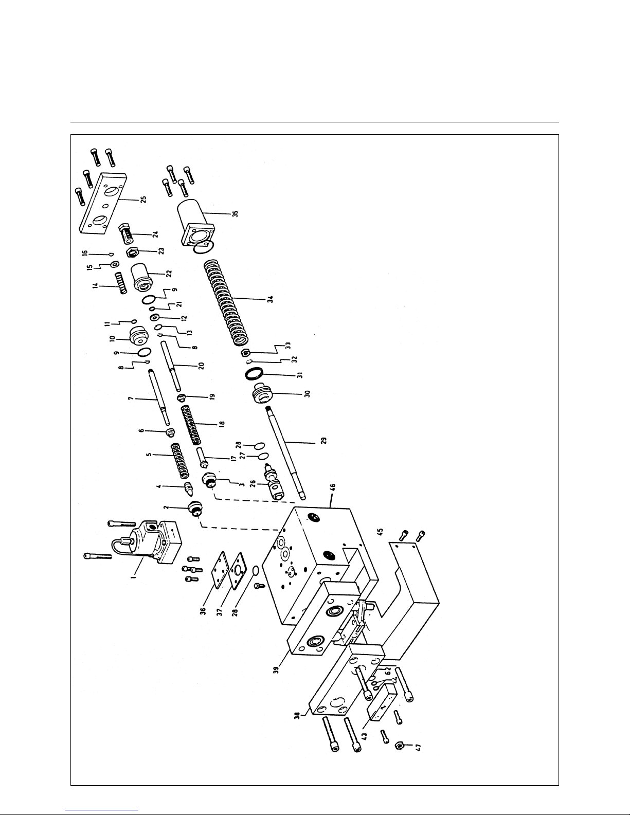
Return Nozzle Rod MAT
Functional description
The oil delivered by the burner pump will enter the feed pipe
(9) via the connection block (10).
Then it flows through t he feed pipe (9) at the pre-s et pressure
directly to the return nozzle. Part of the oil delivered will be
returned through the return flow pipe (6) via the return flow
hole of the nozzle.
The return flow rate is controlled according to the required
output using an output pressure control valve.
Approved shut-off valves are installed directly upstream of
the inlet to the nozzle rod in the oil feed and oil return lines.
1. Union nut
2. Nozzle plate
3. Intermediate plate
4. Swirl chamber
5. Nozzle rod
6. Return pipe
7. Feed flow
8. Return flow
9. Feed pipe
10. Connection block
Page 32

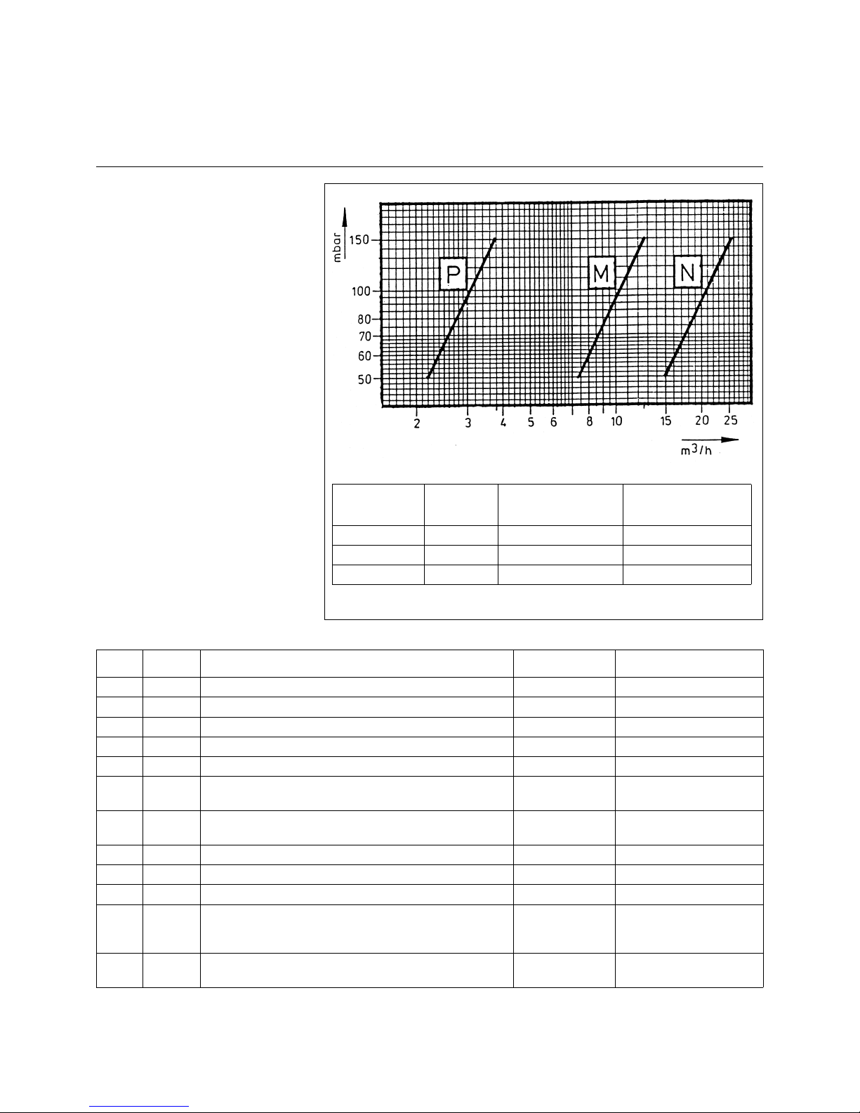
32
Throughput Rate Charakteristics
Light Fuel Oil
Return Nozzle MK 27
Article-No.: 145.513.5899
Oil [kg/h]
m
·
2 alpha [°]
p return [bar]
T est cond ition s:
Page 33

33
Throughput Rate Charakteristics
Light Fuel Oil
Return Nozzle MK 27
Article-No.: 145.513.5902
Oil [kg/h]
m
·
2 alpha [°]
p return [bar]
T est cond ition s:
Page 34

34
Throughput Rate Charakteristics
Light Fuel Oil
Return Nozzle MK 27
Article-No.: 145.513.5913
Oil [kg/h]
m
·
2 alpha [°]
p return [bar]
T est cond ition s:
Page 35

35
Throughput Rate Charakteristics
Light Fuel Oil
Return Nozzle MK 27
Article-No.: 145.513.5924
Oil [kg/h]
m
·
2 alpha [°]
p return [bar]
Test conditions:
Page 36

36
Throughput Rate Charakteristics
Light Fuel Oil
Return Nozzle MK 50
Article-No.: 145.513.5946
Oil [kg/h]
m
·
2 alpha [°]
p return [bar]
T est cond ition s:
Page 37

37
Throughput Rate Charakteristics
Light Fuel Oil
Return Nozzle MK 50
Article-No.: 145.513.5957
145.513.5968
Oil [kg/h]
m
·
2 alpha [°]
p return [bar]
T est cond ition s:
Page 38

38
Throughput Rate Charakteristics
Light Fuel Oil
Return Nozzle MK 50
Article-No.: 145.513.5979
Oil [kg/h]
m
·
2 alpha [°]
p return [bar]
T est cond ition s:
Page 39

39
Throughput Rate Charakteristics
Light Fuel Oil
Return Nozzle MK 50
Article-No.: 145.513.6007
145.513.5991
Oil [kg/h]
m
·
2 alpha [°]
p return [bar]
Test conditions:
Page 40

40
Throughput Rate Charakteristics
Heavy Fuel Oil
Return Nozzle MK 27
Article-No.: 145.513.5899
Oil [kg/h]
m
·
2 alpha [°]
p return [bar]
Test conditions:
Page 41

41
Throughput Rate Charakteristics
Heavy Fuel Oil
Return Nozzle MK 27
Article-No.: 145.513.5902
Oil [kg/h]
m
·
2 alpha [°]
p return [bar]
Test conditions:
Page 42

42
Throughput Rate Charakteristics
Heavy Fuel Oil
Return Nozzle MK 27
Article-No.: 145.513.5913
Oil [kg/h]
m
·
2 alpha [°]
p return [bar]
Test conditions:
Page 43

43
Throughput Rate Charakteristics
Heavy Fuel Oil
Return Nozzle MK 27
Article-No.: 145.513.5924
Oil [kg/h]
m
·
2 alpha [°]
p return [bar]
Test conditions:
Page 44

44
Throughput Rate Charakteristics
Heavy Fuel Oil
Return Nozzle MK 50
Article-No.: 145.513.5946
Oil [kg/h]
m
·
2 alpha [°]
p return [bar]
Test conditions:
Page 45

45
Throughput Rate Charakteristics
Heavy Fuel Oil
Return Nozzle MK 50
Article-No.: 145.513.5957,
145.513.5968
Oil [kg/h]
m
·
2 alpha [°]
p return [bar]
Test conditions:
Page 46

46
Throughput Rate Charakteristics
Heavy Fuel Oil
Return Nozzle MK 50
Article-No.: 145.513.5980
Oil [kg/h]
m
·
2 alpha [°]
p return [bar]
Test conditions:
Page 47

47
Throughput Rate Charakteristics
Heavy Fuel Oil
Return Nozzle MK 50
Article-No.: 145.513.5979
Oil [kg/h]
m
·
2 alpha [°]
p return [bar]
Test conditions:
Page 48

48
Throughput Rate Charakteristics
Heavy Fuel Oil
Return Nozzle MK 50
Article-No.: 145.513.5991
145.513.6007
Oil [kg/h]
m
·
2 alpha [°]
p return [bar]
Test conditions:
Page 49

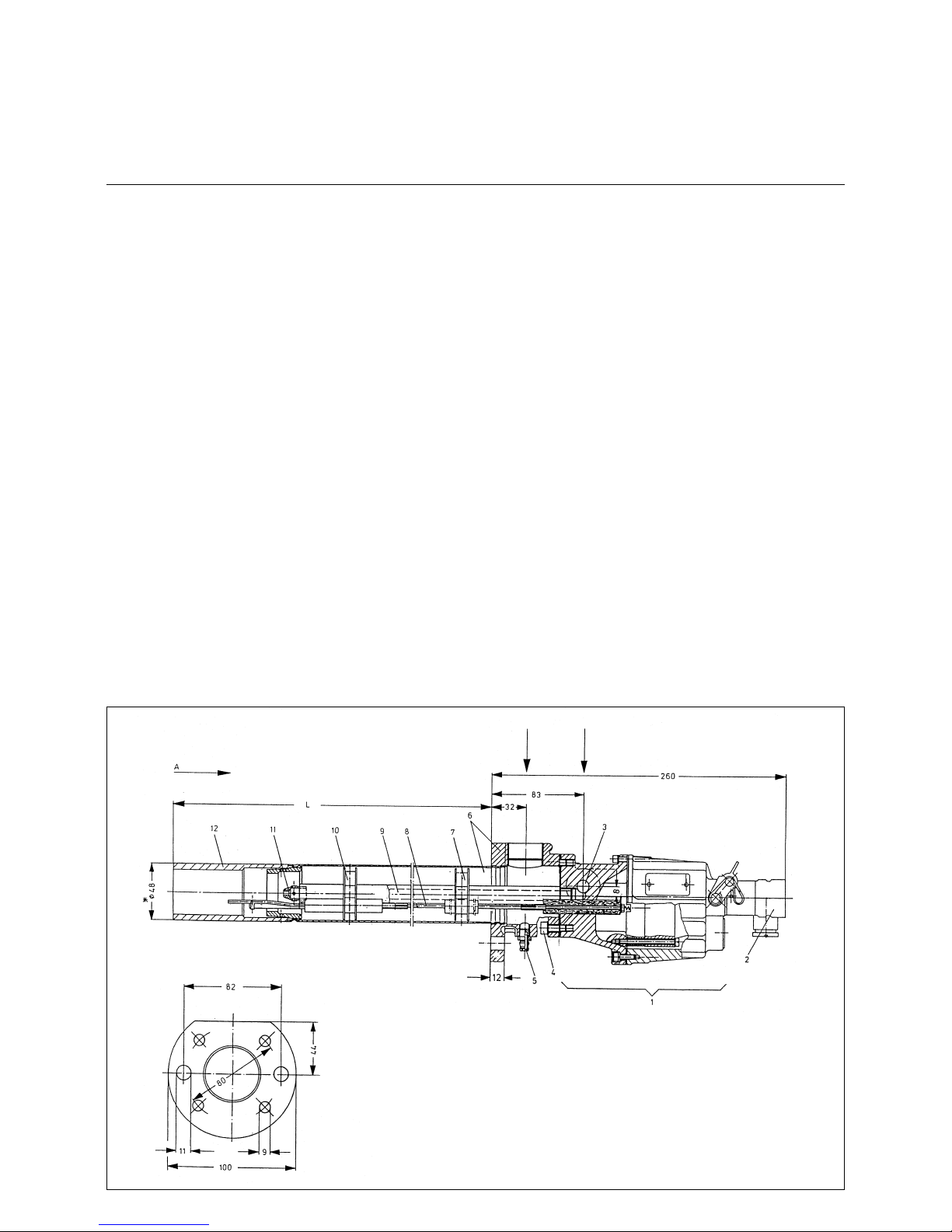
49
Dimensions of the Mixing Unit
(standard versions)
RPD 30 - RPD 80
Page 50

50
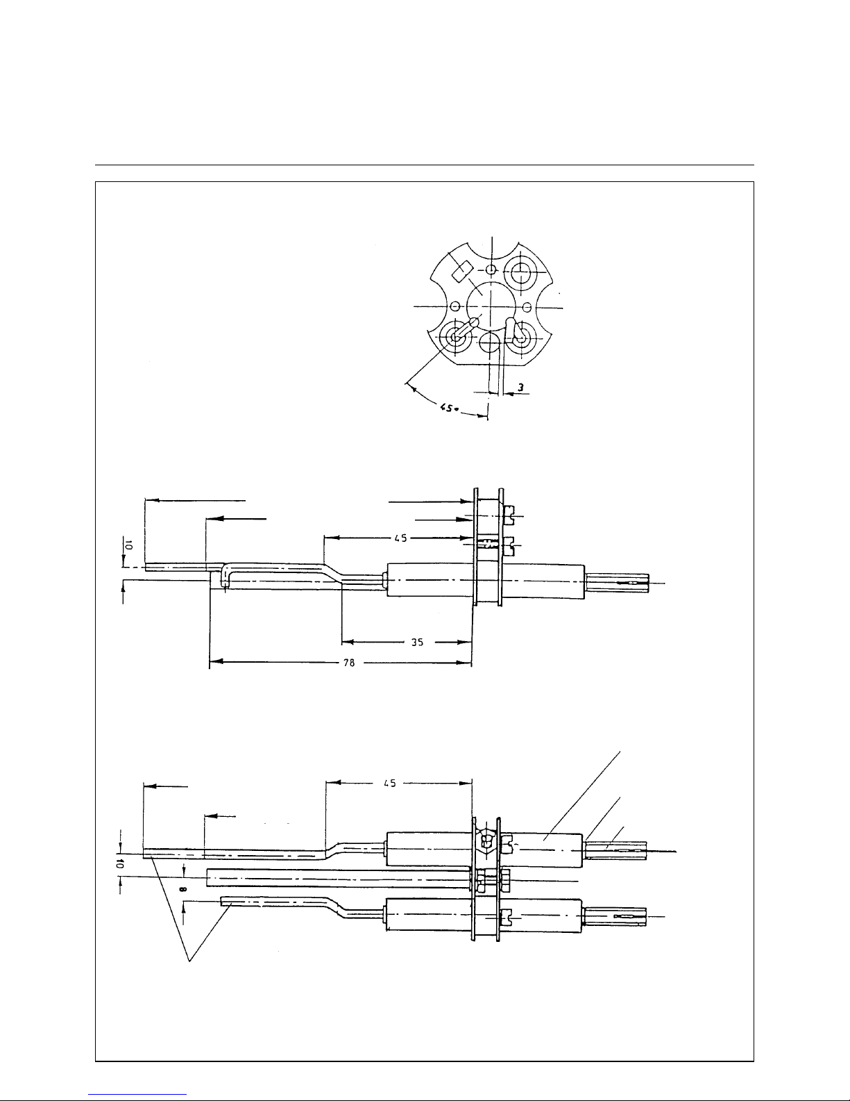
Draw-out and Swing Mechanism
Burner Settings
Draw-out and swing mechanism
The duobloc burners type RPD are
equipped with a draw-out and swing
mechanism. This makes it possible to
pull out and swing away the complete
central tube for maintenance access to
the mixing head and for adjusting the
mixing and ignition units.
Prior to this, the fastening bolts of the
central tube must be unscrewed. The
baseplate of the cen tral tub e carries t he
ignition burner, flame detector, nozzle
rod assembly (only for oil and dual-fuel
burners) and primary air connection.
After the central tube has been remo-
ved, the air damper in the burner housing will also be accessible.
NOTE: Before removing and swinging
away the central tube take care to
mount the draw-out and swing mechanism, discon nect the electric plug connectors of the flame detector and
ignition bu rner, remove th e primary air
connection and discon nect the oil hoses
(in oil and dual-fuel burners) with the
quick-action couplings provided for this
purpose.
Burner head adjustments
Burner combustion head
adjustments
In order to enable service work on the
burner combustion head and for adjustments of the ignition system the complete burner insert ca n be removed (see
burner hinge arrangement). In case of
component replacements or service
work on the components of the burner
head the correct position of the burner
head components have to checked and
if necessary the appropriate adjustments have to be carried out.
The correct measurem ents can be seen
in the burner dimensional sheet .
The ignition electrodes must be set
according to the dimensions shown in
the diagramm.
As the spray pattern of the oil nozzle
depend on nozzle size the given dimensions can only be approximations. It
may be necessary for the commissioning engineer to alter the base settings to
achieve the best start performance. The
distance between nozzle tip and turbulator face depends on the nozzle spray
pattern and the size of the turbulat or
core hole. The distance has to be adjusted by the commissioning engineer so
that the oil cone will impinge on the turbulator.
The works setting of the burner head is
carried out as shown in the dimensional
sheet. In the base setting the nozzle
face is positioned flush with the turbulator inner hole i.e. setting "0".
It is recommended to note the distance
between nozzle rod positioning bush
and the end of the protruding nozzle rod
as reference position.
Burner combustion head
1 Burner tube
2 Flame tube
3 Cylinder for air stabiliz ati on
4 Ignition Burner
5 Turbulator
6 Nozzle
7 Primary air duct
8 Gas nozzle
9 Gas lances
Page 51

51
Air Flow Adjustment
Oil Flow and Gas Rate Adjustment
Air adjustment
Check that the air swirler setting is in
accordance with the furnace/ combustion chamber geometry and re-set if
required. In order to ensure uniform distribution, close the air swirler at the air
pipe entry against air inlet. The air cur ve
of the compound con troller is factor y-set
so that the air cylinder is closed at minimum settings and open at maximum
settings.
The combustion air ratio (sec ondary air)
to the fuel can be obtained over the
whole of the outp ut rang e by turning the
screws, which is then checked by
measuring the exhaust.
Before the compound controller screws
can be adjusted, the lock nuts on the
front face and underside of the compound controller must be loosened. Setting of the primary ai r is a lso c arrie d o ut
via a cam disk and it can be set accurately by adjusting the threaded studs as
required. With a large control range the
minimum combustion output is set by
means of the primary air.
During adjustment care must be exercised to ensure that over the whole of the
control range the air pressure at the
central pipe (primary side) is 1.5 - 2
mbar higher than the combustion chamber pressure.
Oil adjustment
For taking into operation, the oil control
block with flow control valve in the
return line will be preset. The pump
pressure is set at approx. 28 bar and
the pressure upstream of the control
valve at approx. 5 to 18 bar. After loosening of the lock screws of the socketheaded studs and sliding ball, the control curve is adjusted over the whole
control range by m eans of the cam disk,
after which setting is then locked with
the lock screws.
Heavy fuel oil
Heavy fuel oils must generally be heated up. On the one hand, this is performed in the fuel oil storage tank to keep
the oil in a pumpable state because the
temperature must be above the se ttin g
point. Further preheating is required in
the service tank, fluid preheater or electric preheater to ensure the heavy fuel
oil can be properly atomized and burns
readily. The level of preheating depends
on the viscosity of the fuel oil and can
be determined from the viscosity-temperature diagram. The atomizing viscosity is at 12 to 15 cSt.
Gas adjustment
The gas damper is connected to the
mechanical compound controller by
means of a transmission arm.
The gas cam of the compound controller is factory-set so that the gas damper
is closed in its minimum position and
open in its maximum position.
The minimum and maximum positions
and the intermediate positions of the
gas damper are also adjusted with the
electronic compound controller . The gas
pressure must be corrected by means
of the gas pressure controller if necessary. The setting must be checked by
making a combustion analysis.
Spindleflame
Long
flame
Average length
flame
Short
flame
Air swirler
position
Flame formation
POS 1
Air swirler angle
Pressure loss
0 - 20°
30 mbar
POS 2
Air swirler angle
Pressure loss
20 - 40°
38 mbar
POS 3
Air swirler angle
Pressure loss
40 - 55°
45 mbar
POS 4
Air swirler angle
Pressure loss
55 - 70°
55 mbar
Page 52

52
Mechanical Compound Controller
1 Fuel-air compound cont roll er
mounting bracket
2 Secondary air damper control lin-
kage
3 Primary air control arm
4 Primary air control linkage
5 Primary air angular control arm
6 Spring-loaded sliding block for
gas control
7 Hexagon socket head screw with
pressed-in sliding ball (locked by
means of hexagon socket head
screws on end face of cam wheel)
8 Spring-loaded sliding block for
secondary combustion air
9 Cam disk on drive shaft
10 Drive shaft
11 Spring-loaded sliding block for pri-
mary air
12 Spring-loaded sliding block for oil
flow rate control
13 Transmission rod fo r gas flow rate
control damper
14 Actuator with disconnecting unit
for manual operation
15 Hand wheel for manual adjust-
ment of mechanical compound
controller
16 Return flow connection (only
heavy oil)
17 Feed line hose connector
18 Solenoid stop valve
20 Pressure gauge stop valve
21 Oil pump pressure gauge
22 Oil feed connection from burner
pump
23 Oil pressure switch in fee d line fo r
lack-of-oil monitoring
24 Oil return flow connection
25 Oil pressure switch in return line
for oil overp ressure monitoring
26 Limit switch for oil and gas opera-
tion
27 Oil flow rate control linkage
28 Bypass change-over valve (f lus-
hing valve)
29 Pump pressure adjuster for built-
in primary pr essure controller
30 Bypass solenoid valve (flushing
valve)
31 Return pressure gauge (only
heavy oil)
NOTE: For heavy oil operation, the oil
control block and oil flow rate controller
are equipped with electric heaters.
Page 53

53
Pressure Setting
Oil pump pressure setting
Before commissioning the pum p and oil
pipes must be primed and vented.
1. Pump pressure
- 28 to 30 bar for light fuel oil
- 30 to 32 bar for heavy fuel oil
So as to protect the pump against
excess pressures, the oil pressure control valves of the high pressure pump
have been factory set to 40 bar. The
effective pump pre ssure is s et an d ad justed at the burner control bl ock or at the
pressure control valve.
2. Pressure setting at the control
valve (loop feeder pipe) at the
burner pipe pressure
Light fuel oil setting
Loop feeder pipe pressure 1,2 - 1,6 bar
Heavy fuel oil setting
In order to avoid evaporation of the
water in the fuel oil, the pressure in the
loop feeder pipe must be at least
-see table:
Pressure control valve
In the piston-type pressure control
valve, a pisto n (1) movably arranged in
a cylinder is pressed against the valve
needle (3) by a spring (2). As the pressure on the side of the valve needle
rises above the spring pressure, the
piston will be lif ted a nd the o il cau sed to
flow over to the pressureless side.
For the installat ion of overflow valves of
this type the following general information should be observed:
The spring side (spring can be seen
from outside) must in any case be chosen to be the return side, i.e. the pressureless side. Consequen tly, the
direction of overflow is from the pressurized side to the pressureless spring
side. Any counterpressure on the return
side must thus be added to the s elected
spring pressure setting.
It is of no consequence for the opera tion
of this type of valves whether they are
mounted in continuous lines or at line
ends.
The desired pressure is selected by
means of the set screw (4). Turning the
set screw (4) clockwise will increase th e
pressure, and turning it counterclockwise will reduce the pressure.
Oil temperature
at the burner
Loop feeder
pipe pressure
125 °C 3,0 bar
130 °C 3,5 bar
135 °C 4,0 bar
140 °C 4,5 bar
4
2
1
3
Return
Feed
Light oil version
Heavy oil version
Page 54

54
Removal and Replacing the Shaft Seal
of the Return Flow Nozzle Assem bly DG 75
Removal:
Before removal make a note of all relevent dimensions of the transmission
lever etc.
1. Remove lock-nut (2), dom ed nut
(1) and the connecting piece (3).
2. Remove end nut (4).
3. Slide out the shaft seal (must no t
be re-used).
Replacement:
1. In place of the end nut (4) use
location tool (5).
2. Remove plug in sleeve (6) (fitted
for protection of sleeve only) and
move sleeve over threads and
valve needle.
3. Using a piece of pipe, slide the
new seal over sleeve (6) through
the locating tool (5) u ntil it bottoms
in the seal housing (8). (The seal
should not be compressed).
4. Remove the special tools.
5. Replace the end nut (4), connecting piece (3), lock nut (2) and
domed nut (1).
6. Tighten the locking nut to the
domed nut.
Page 55

55
Start-up
Oil Pressure Switch
Air Pressure Switch
Oil pressure switch
Oil pressure switches are provid ed to
burners for monitoring the oil pressure.
Depending on the burner de sign, the oi l
pressure switches can be installed either in the return line only or in both the
return line and feed line. The cut-out
pressure will be selected depe ndi ng on
the burner system data (ring line pressure, oil nozzle, etc.).
Oil pressure damper
An oil pressure damper or a capillary
pipe may be installed in the connection
fitting (2) to make up for oil pressure
variations.
Operating pressure adjustment
For adjusting the operating pressure,
remove the setting know (1) by pullin g it
upward and reinstall it again the othe r
way round. After the adjustment has
been completed mak e sure to i nstall th e
setting know in its original position
again.
Switching difference
The switching difference may be selected on the pressure switches within the
limits shown in the table. For the adjustment, turn the threaded pin in the set
screw (3) for the switching point. One
turn will change the s witching diff erence
by approx. 20 % of the tot al range of the
switching difference. The oil pressure
switch has a facility for attaching a seal.
1
2
3
Type
Setting
range
Switching
difference
Location
DSB 158 F... 0 - 25 bar 1,0...7,5 bar Return line acc. to EN 267; alterna-
tive if finer switch difference required
DSB 146 F... 0 - 10 bar 0,7... 4,0 bar Optional feed line and return line acc .
to EN 267; aggressive media
DSF 158 F... 0 - 25 bar 1,5... 8,0 bar Optional return line acc. to EN 267;
aggressive media, alternative if finer
switch difference required
DSF 152 F... 0 - 16 bar 1,2...3,5 bar Return line acc. to EN 267; alterna-
tive if finer switch difference required
Air pressure switch
The air pressure switch is provided for
monitoring the pressure of the combustion air fan.
The pressure switch DL 50A has been
designed for switchi ng on, of f or over an
electric circuit in the case o f chang es of
the actual pressure levels from the setpoint setting. The pressure switch DL
50A can be used as overpressure,
vacuum or differen tia l pre ssure mo nit or
for air and non-aggressive gases but
not for gases according to DVGW
Worksheet G 260/l.
Determining the differential preflushing pressure and adjusting the
differential pressure switch
• Burner in the pre-aeration phase.
• Mea sure pressure on test
connection (2).
• Measure vacuum on test
connection (3).
• Add the measured pressures.
• Set the scale to 90% of the calcul ated
value.
Certification
The pressure switch has bee n tested in
accordance with DIN 3398 Part 2 and is
registered by CE/DIN-DVGW. It has
been registered in other important gas
consumption countries.
Switch function test
Test buttons are provided to check the
switch functions for proper operation
(with safety cut-out and interlock). The
burner is normally run in partial-load
condition when testing the safety
functions. On pressing button (4) the
vacuum will be removed which causes
the differential pressure to drop below
the required level. If it is necessary to
test the pressure switch functions under
full-load conditions this may be done by
pressing button (1).
Page 56

56
Setting Pressure Switches and
Control System
Setting of the oil pressure switch
The oil pressu re switch is factory-set.
The supply pressure switch is set in
such a way, that perfect atomization is
guaranteed. The return p r es su re s witc h
is factory-set to 2 bar.
The pre-set return pressure should normally be 1 bar above the loop feeder
system. After having set the correct
pressure ensure that the
setting screw is securely locked.
Setting of the gas pressure switch
Remove the protective hood. Measure
the gas flow pressure at full load and
reduce by 20 % to obtain the shutdown
pressure.
Proceed with turning t he scale disk until
the desired shutdown pressure is opposite to the arrow. Note that scale values
are approximate values only.
Then slowly close the gas stop valve
until the desired shut down pressur e has
been reached. Readjust the scale disk
until the burner stops.
Put the protective hood back in place
again and tighten bolts.
Setting of the air pressure switch
The differential pressure between burner housing (overpressure) and air box
(subatmospheric pr essure) is me asured
with the burner in full-load condition.
The pressure setting of the air pressure
switch must therefore be smaller than
the different ial pressure measured. For
adjustment, remove the pro tective ho od
and turn the setting scale accordin gly.
Switching functions of air pressure
switch/gas pressure switch
With increasing pressu re:
P1 opens
P2 closes
With decreasing pressure:
P1 closes
P2 opens
An industrial controller type KS 92 is
used for the steplessly adj ustab l e bur -
ners. This co ntroller has been specifically designed for use w ith bu rner
systems. It is mainly employed for temperature or pressure control operations in
conjunction with burner s wi t h a st eadily
adjustable fuel throughput rate. A specific
software system is provided for adjusting
the controller to the contro lled variable,
the desired setpoint range and the way of
actual-value recording.
Technical documentation KS 92 PMA
Infinitely variable control
(modulating) with RWF 32 controller
A universal controller type RWF 32 can
also be used with infinitely variable controllable burners. This controller is specially designed for furnace temperature
and pressure control of burners using
constantly changing types of fuel.
Depending on the use, the RWF 32 will
function as either PID, PD or P controller. As the P part, which is correcting
time and the D part can be adjusted to
cover a wide range of limits, it is possible to adapt the control behaviou r of the
installation to ex act st a ndards. The operating time of the drive for compound
control of fuel and ai r mu st be at least 2
secs. for the "small fla me - nomi nal load
setting" range.
The actual value reading (temperature,
pressure or combustion chamber pressure) is achieved by means of sensors
and range or zone plugs in th e form of a
resistance value. The control output of
the controller is a floating three-point
switch used to control reversible servomotors. The control signals for the
actuating direction OPEN (y1) and
CLOSED (y2) are displayed by LEDs,
whilst the adaptation of the controller to
the control led variab le and the requ ired
specified value ra nge is effected vi a th e
so-called range or zone plugs, which
form the sensor part of the controller
measuring bridge. The range or zone
plug is also fitted with the setpoi nt scale.
On the other hand, the setpoint value
generator itself, which can be changed
to be a remote setpo int value g enerator,
is a fixed component of the controller.
Setting the controller
Setting a complete, infinitely variable
heating installation required excellent
technical and controll er knowledg e. The
actual setting and commi ssioning of the
installation is made considerably easier
by the special setting instructions
issued with the RWF 32 controller.
Comprehensive special issues are
available if required.
The differential pressure between the
burner housi ng (excess pressure) and
the air receiver (negative pressure) is
measured during the full load adjustment. The pressure set at the air pressure switch must be below the
measured differ ential pre ssure. To carry
out the setting remove the protective
cover and turn the setting scale as
required.
Gas pressure switch
P
1
2
P
Air pressure / gas pressure
switch circuit
KS 92
Oil pressure switch
Page 57

57
Automatic Furnace Controller LFL 1... / LGK 16...
The LGK 16… type controller is designed to control and monitor burners
working according to a stepwise or
modulating principle. A detailed functional description with technical data and
project planning information with
respect to the automatic combustio n
controllers can be found in the annex
and in the documents
LFL 1...-7451 D
LGK 16...-7785 D
Functional diagram
LFL 1... / LGK 16...
A = Starting type interval
A-B= Flame development interval
B = Burner has reached operating
position
B-C=Burner operation
(heat generation)
C-D= regular shut-off
t1 Pre-ventilating time
t2 Safety time
t3 Pre-ignition time
t4 Fuel valve enable
t5 Load regulator enable
t11 „OPEN“ run time of air damper
t12 „CLOSE“ run time of air damper
R = Temperature or pressure
controller
G = Fan motor
Z = Ignition transformer
BV= Fuel valve(s)
LR= Load regulator
LK= Air damper
RV= Steadily adjustable fuel valve
FS= Signal of flame
ZBV= Ignition burner valve
Page 58

58
Flame Monitor
Sensor Current Measurement
Flame monitor with UV sensor
The UV radiation of hot flame gases is
utilized for generating the flame signal.
The radiation detector used is a UVsensitive tube with two electrodes and
being live all the time. This UV tube will
ignite when subject to light from the
190-270 nm range of the spectrum and
thus cause a current t o flow to the f lame
signal amplifier.
The UV tube will not respond to the
after-glowing refractory lining of the furnace, sunlight, daylight or light of the
boiler room lighting system.
The service life of the UV tube is about
10,000 hours at ambient temperatures
up to 50°C; higher ambient temperatures will considerably reduce its service life.
Burners operated continuously or intermittently for more tha n 24 ho urs witho ut
interruption (e.g. boiler sequence control) or burners operated on steam boilers must be equipped with the
automatic furnace controller of type
LGK 16... and its associated self-controlling flame monitoring circuit (QRA
5...).
For data and desig n instruc tions refe r to
automatic furnace controller:
LFL 1... No. 7451 D
LGK 16... No. 7785 D
Sensor currents
* See technical data for automatic
furnace controller LFL 1 / LGK 16...
** See data on unit KF 8832 for sensor
current measu rement.
UV current measurement with QRA 5
For an accurate UV current measurement it is reco mm end ed to make use of
the tester KF 8832. If a normal meter
(microammeter) is used for UV current
measurement it is advisable to make
the measurement as shown in the
figure. For this, a capacitor
C = 470 μF, 1 5V (or with higher electric
strength) must be integrated in the
measuring c ircuit.
Meter: 100 μA/Ri = 3 kΩ
Connect the meter between the automatic furnace controller and the UV
flame sensor QRA 5... (terminal 22 (-)
and 5 (+)).
Take care to observe the right polarity.
Alignment of the UV sensor QRA 5...
The mounting flange is movable supported on the sensor tube to allow the
exact alignment of the sensor window
relative to the direction of incidence of
the UV radiation.
NOTE: The terminal (22) must be connected to earth all the time.
Cleaning the sensor
Check the UV sensor window for possible accumulation of dirt at regular intervals and clean if required . Take care the
sensor window is free of dust all the
time.
If upon cleaning the sensor does not
properly work it will be required to
replace it by a new one.
Automatic
controller
Minimum
required
Maximum
possible
Monitor with UV with UV
* LFL 1... 70 μA 630 μA
* LGK 16... ** **
Recommended instrumen t range:
UV monitor 0 - 1000 μA
Autom. furnace controller LFL 1...
UV sensor with QRA 2...
Autom. furnace controller LGK 16...
UV Sensor with QRA 5...
Page 59

59
Actuator Type ARIS, 4, 4a, 5
Description
The actuator type ARIS-N is designed
as a controlling element for oil/gas or
dual-fuel burners wi th s li ding or modulating control concept. The actuator is
equipped with a short-circuit-proof synchronous a.c. motor which drives a
shaft via a maintenance free spur-ge ar
unit with permanent grease lubrication.
The shaft end carries a coupling for
operating the controlling element for
fuel and combustion air. The actuator is
designed for two-wire co ntro l by c ont rollers or switching uni ts with change-over
contact (single-wire control is possible).
A feedback potentiometer is used as a
optional feature.
Technical Data:
Voltage: 230 V +/- 10% Protection class: IP 54, DIN 400 50
Frequency: 50 Hz (60 Hz) Installation position: no restriction
Operating time: 25 - 30 sec. at 90°
Torque: N 4 40 Nm
N 4A 60 Nm
N 5 110 Nm
Weight: N 4 3,4 kg
N 4a 3,4 kg
N 5 5,8 kg
Contacts: max. 250 V 10(3)
A
Ambient
temperature: -15 °C till + 60 °C
Adjustment
A service switch for manual/automatic
operation is provided for adjusting the
actuator/controlling elemen t.
This service switch comprises:
1x manual/automatic tumbler switch
1x left/right pushbutton switch con-
nected according to the sketch
(left)
For using the actuators with service
switch (no handwheel) care should be
taken to observe the following:
• An additional permanent phase must
be installed from the actuator to the
control cabinet via the terminal box or
directly to the control cabinet.
• An additional terminal must be mounted in the terminal box.
Page 60

60
Solenoid Safety Valves
For fuel oil EL, L, M, S according to DIN 51603
TECHNICAL DATA
Function 2/2 electromagnetic safety shut-off valve and rapid action device actuated in oil-firing
equipment according to DIN 32725 (DIN EN 264). TÜV tested. Used as well in connection with atomizing oil burners according to DIN 4787 and oil firing systems with steam
boilers according to TRD 411.
Port sizes G1/2 / flange
Mounting Direct pipe mounting or with two threaded holes at the lower connection area (please
refer to dimensional drawing).
Mounting position Unrestricted
Material specifications Valve body from brass. Internal parts from stainless steel. Bearing plate from ruby and
elastomere from oil resistant viton (FKN).
Pressure range Please refer to the table.
Switching times With fuel oil EL and alternating current coils:
321 H types: switch-on operation approx. 300 ms,
switch-off operation approx. 50 ms
121 G types: switch-on operation approx.50 ms,
switch-off operation approx. 20 ms
Media Fuel oil EL, L, M, S (DIN 51603), please refer to the table.
Filter Filters according to DIN 32727 must be connected in series to the 321 H/F valve
Authorized minimum
temperature
0 - + 160°C
Ambient temperature 0 °C to 60 °C
Flow factors kv = 2 to 60 (please refer to the table). The tolerance conc ern ing flo w f act ors is +/- 15 % .
Electrica l components 121 G and 321 H types:
High temperature and high capacity coil with screw terminal connection.
Coil housing Metallic housing covered with epoxy resin, 360° rotating, with Pg11 cable screwing.
System of protection IP 44. Galvanized metallic housing, 360° rotating, with Pg11 cable
screwing. System of protection IP 67.
Voltage
( alternating current only )
115 V / 50 HZ - 120 V / 60 Hz (T1)
V oltage tolerances + 10 % to - 10% of the line voltage.
Insulation class H 180 °C for 483824 and 483541coils .
Switch-on time 100 % admissible.
Power rating 19 Watt
Page 61

61
Solenoid safety valves
321 H types
Application: safety shut-off valve as
rapid acti on device. Used as well in
connection with atomiz ing oi l burners
according to DIN 4787 and oil firing
systems with steam boilers ac cording
to TRD 411. A strainer must be connected.
Type:
2/2 pre-controlled, closed when deenergized.
121 G types
Application: safety shut-off valve as
rapid action device for use in return
pipes of atomizing oil burners according to DIN 4787 and TRD 411. With
regard to current standards this valve
must be connected in series with the
valve mounted in the supply line
(please refer to the schematic drawing).
Type:
2/2 directly controlled, closed when deenergized by spring force.
When the solenoid valve is de-energized the retur n line medium pressure
(against arrow direction) s till opens the
valve seat until 0,15 bar.
arrow stamped on
the valve body
Page 62

62
2/2 Way Valve Type MK 15
General specifications Options
Ports MK threads G3/8"-G1" special threads
Function NC NO
Pressure range bar 0-16 / 0-40 / 0-64 / 0-100 >100 bar upon request
Flow rate
m
3
/h
4,8
Media gaseous-liquid- highly viscous-gelatinous-contaminated
Flow direction A>B as marked bi-directional (max. 16 bar)
Switching cycles 1/min 200
Media temperature C° DC: -40 to +100/TÜV+140
AC: -40 to +100/TÜV+140
-40 to +180
-40 to +180
Ambient temperature C° DC: -40 to +80
AC: -40 to +80
Nominal voltage U
n
DC: 24 V
AC: 230 V 40-60 Hz
TÜV-version
TÜV-version
special voltages upon request
DC: 24 V
DC: 200 V
Actuation DC
AC
direct-current magnet
direct-current magnet
with integrated rectifier
above 100°C and in TÜV version with
seperate rectifier
Protection IP 65
Energized duty rating ED 100%
Connection Pg9
Pg11
appliance plug socket acc. DIN 43 650
Form A, 4 positions x 90°
terminal box
Additional equipment illuminated plug with varistor
Current consumption N-coil
H-coil
24V -DC 1,60 A
230V 40-60Hz -AC 0,15 A
24V -DC 2,30 A
230V 40-60Hz -AC 0,24 A
Function
valve
normally closed
symbol:
NC
valve
normally open
symbol:
NO
2/2
way valve:direct acting
Orifice: DN 15 mm
Design: pressure balanced,
with spring return
Body
materials: 1. brass (Ms 58)
2. steel, galvanized
3. brass, nickel plated
4. steel, nickel plated
5. without non-ferr . me t.
6. V4A (1.4571)
7. TÜV
Valve seat: synth.resin on metal
seal materials:teflon, viton,
neoprene, EPDM
Page 63

63
2/2 Way valve type MK 15
items circled are included in
spare part kit
1 connecting port
2 connecting port
3 valve seat u nit
4 magnet unit
5 armature-control tube
6 gland
7 gland
8 retaining ring
9 locking ring
10 return spring
11 spring housing
12 locking Ring
13 hex head bolt
14 hex nut
15 lock washer
16 seal (dynamic)
17 seal (dynamic)
18 O-ring
19 gasket
20 terminal box unit
21 sealing ring
22 shading ring
23 appliance plug socket unit
24 seal
Page 64

64
2/2 Way Valve Type MK 20
General specifications Options
Ports MK thre ads G3/4"-G11/4" special threads
Function NC NO
Pressure range bar 0-16 / 0-40 / 0-64 / 0-100 >100 bar upon request
Flow rate
m
3
/h
7,4
Media gaseous-liquid- highly viscous-gelatinous-contaminated
Flow direction A>B as marked bi-directional (max. 16 bar)
Switching cycles 1/min 150
Media temperature C° DC: -40 to +100/TÜV+140
AC: -40 to +100/TÜV+140
-40 to +180
-40 to +180
Ambient temperature C° DC: -40 to +80
AC: -40 to +80
Nominal voltage U
n
DC: 24 V
AC: 230 V 40-60 Hz
TÜV-version
TÜV-version
special voltages upon request
DC: 24 V
DC: 200 V
Actuation DC
AC
direct-current magnet
direct-current magnet
with integrated rectifier
above 100°C and in TÜV version with
seperate rectifier
Protection IP 65
Energized duty rating ED 100%
Connection Pg9
Pg11
appliance plug socket acc. DIN 43 650
Form A, 4 positions x 90°
terminal box
Additional equipment illuminated plug with varistor
Current consumption N-coil
H-coil
24V -DC 1,60 A
230V 40-60Hz -AC 0,15 A
24V -DC 2,30 A
230V 40-60Hz -AC 0,24 A
M
K
2
0
Function
valve
normally closed
symbol:
NC
valve
normally open
symbol:
NO
2/2
way valve:direct acting
Orifice: DN 20 mm
Design: pressure balanced,
with spring return
Body
materials: 1. brass (Ms 58)
2. steel, galvanized
3. brass, nickel plated
4. steel, nickel plated
5. without non-ferr . me t.
6. V4A (1.4571)
7. TÜV
Valve seat: synth.resin on metal
seal materials:teflon, viton,
neoprene, EPDM
Page 65

65
2/2 Way valve type MK 20
General operating instructions
To ensure the proper operation of our
maintenance-free units care should be
taken to observe the following points:
1. Prior to installing the valve in the
pipeline system make a check
that the latter system is absolute ly
clean to avoid that any particles
left behind by the line mounting
work can be flus hed in to the valv e
when taking the system into operation.
2. Valves with threaded connections
should be installed to the pipeline
system in a way that the frictional
connection is not made in the longitudinal axis of the valve. For
screwing in the pipe, t he mounting
tool should be attached to the
valve socket to which the pipe is
mounted. For valves with flanged
connection, care should be taken
that no tensile, compressive and
shearing loads are brought to
bear on the valve because this
could lead to functional trouble.
The direction of flow indicated on
the 2/2-way valves by arrows
should in any case be adhered to.
3. For the electrical connection, unscrew the terminal box cover or
install the plug connectors. Prior
to connecting the cables check
that the voltage applied is as
stated on the rating plate. Take
care to observe the marking attached to the terminal because if the
connections are wrong ly fitt ed this
may cause damage to the valve
when taken into operation.
items circled are included in
spare part kit
1 connecting port
2 connecting port
3 valve seat unit
4 magnet unit
5 armature-control tube
6 gland
7 gland
8 retaining ring
9 locking ring
10 return spring
11 spring housing
12 locking Ring
13 hex head bolt
14 hex nut
15 lock washer
16 seal (dynamic)
17 seal (dynamic)
18 O-ring
19 gasket
20 terminal box unit
21 sealing ring
22 shading ring
23 appliance plug socket unit
24 seal
Page 66

66
Pipe spring - Glycerine - Manometer
Bimetal - Pointer - Temperature controller
Pipe spring - Glycerine - Manometer
RF 63 - D 701
Port size G 1/4 A radial
Housing from refined steel 1.4301
Diameter 63 mm
Class 1.6
Scale range Order no.
0 - 6 bar 0 - 10 bar 0 - 16 bar 0 - 25 bar 3333 261 128
0 - 40 bar 109 016 0374
0 - 60 bar 109 811 4290
0 - 100 bar 109 811 4303
Bimetal - Pointer - Temperature controller
TBW 31 H
Measuring instrument: Bi-metallic spiral
Port size G 1/4 "
Sleeve and locking screw on the back side
Housing CrNi , Shaft length 50 mm
Diameter 63 mm
Class 1.0
Scale range 0 - 160 °C
Order no. 109 015 9651
Page 67

67
Flushing and Oil Feed Start
Thermostat ATH 22
(only for heavy oil)
Operation
The surface-type dual-therm ostat works
according to the principle of volumetric
expansion. If the temperature of the
fluid in the sensor system consisting of
sensor, capillary line and membrane
changes this will also cause the volum e
to change. The resultant lifting movement of the membrane will actuate the
quick-break switch via a lever.
Switching function TR/TW/STW(STB)
If the temperature available at the temperature sensor exceeds the limit setting this will cause the switching ram of
the microswitch to be relieved of load
via the sensor system and the electric
circuit opened or closed. In case the
temperature falls below the limit setting
(by the switching difference) the microswitch will be returned to its initial position.
T emperature sensor with and without
protective sleeve
The temperature will be sensed by
means of the temperature sensor. Make
sure the temperature sensor is immersed in the fluid over its full length
because otherwise the switching point
may be subject to larger variations.
1 Remote line 2 Temperature sensor
3 Protective sleeve 4 Pressure spring
For code „f“ and connection mode „Ü“
the temperature sensor will be locked
by fitting a clamp to the capillary line
and securing the same by a screw in
the extended sleev e opening. For code s
„f“ and connection modes B, C, D, E,
ES, Q and V the sens or is lo cked by th e
manufacturer by means of the terminal
attached to the capillary line.
Electrical connection
1. Opening the housing
Remove the two sealable fillister-head
screws (1) at the housing top (2) and
remove the latter.
1 Sealable s crews 2 Housing top
3 Housing bottom 4 H ous in g j ourn al
2. Connection
Feed the line through the self-sealing
grommet Pg 11 and connect as shown
on the connection diagram. The connection diagrams relating to the thermostats are fixed to the inside of their
housing tops.
5 Terminal screw
6 Restart button (must move freely)
7 For type attachments s, g and b
8 For type attachment r
9 Self-sealing grommet Pg 11
Connection diagram
Codes 11, 12, 22, 120, 220, 2020
System I and II with change-over contact.
Technical data
Setpoint adjustment:
For code 1:
Adjust switching point fr om out s ide b y
turning the setpoint screw accordingly.
For codes 2, 20, 7, 70:
Remove the top of the housing and
adjust the switching point by turning
the setpoint screw with a s cre w dri ver
watching the interior scale.
Adjusting range: 20-150°C
Maximum switching current:
AC 250 V, 10(2) A, cosϕ=1(0.6)
DC 250 V, 0.25 A
Switching difference in measuring
system filled with liquid
TR, TW 3+1% standard feature
6+2% on request
1.5 ± 0.5% against extra price
Permissible ambient temperature
on switching head and remote line
in use filled with liquid or gas max.
+80°C
Operating fluid
water, oil, air, superheated steam
Protection classification
EN 60 529-IP54
Page 68

68
Gas Connection
For the installation and taking into operation of the gas lines care should be
taken to observe the regulations of
DVGW (German Assoc iation of the Gas
and Water Sector) espec ial ly DVGWTRGI (Technical Regulation for Gas
Installations) and TRF (Technical Regulation for Furnaces).
DIN 4756 and TRD 412 contain specifications for the construction, design and
safety requirements of gas furnaces in
heating installations. Furnace systems
of higher operating pressures are subject to the DVGW Worksheets G 460
and G 461. The gas lines must meet
specifications set out in DVGW-TR GI i n
the case of furnace systems with operating pressures up to 100 m bar or above
100 mbar .
Gas control group with two gas
valves and leak tester:
The gas section is designed in accordance with EN 676 and TRD 412, two
gas valves and leakage tester are
prescribed for burners with a capacity
above 1200 kW.
The operation, mounting and adjus tment of the valve leak testers is described in detail on a separate sheet .
Gas connection pressure:
The gas line must be dimensioned in
accordance with the throughput rate
and the available gas pressure and
installed to the burner on the shortest
possible way with minimum pressure
loss.
To provide the most effective conditions
for start-up, take care that the burner
and gas stop valv e are i nstal led with th e
minimum possible distance between
one another. This means that the 2
nd
gas valve (looking in the direction of the
gas flow) sho uld be mounted in the
immediate vicinity of the burner.
Note the gas pressure loss of the gas
control group and burner. The gas control group can be connected directly to
the gas feed line. Note the order in
which the valves and instruments are
mounted and the direction of flow. Prior
to installation and taking into operation,
check the valves and instruments and
the connection fittings for the possible
accumulation of dirt and foreign matter.
1 Gas stop valve
2 Ignition gas pressure regulator
3 Ignition gas solenoid valves
4 Gas filter
5 Pressure gauge with pushbutton
valve
6 Test burner
7 Gas meter
8 Gas pressure switch
10 Gas pressure regulator with safety
blow-off valve
11 Safety blow-off valve
12 Gas motor valve 1/solenoid valve
13 Gas motor valve 2/solenoid valve
14 Compensator
15 Gas butterfly control valve
16 Gas pilot burner
17 Burner
Gas connection
> 100 mbar
Ignition gas connection
min. 50 mbar
max. 150 mbar
Page 69

69
Gas Motor Valve VK
Gas motor valve VK..
- Automatic shut-off valve of Class
A according to EN 161.
- Sturdy des ig n for long serv ic e life .
- Energy-saving through motor selfstop.
- Available in single-stag e or double
stage design with signal switch.
- Valve housing available in
GGG 50.
- Valve top can be supplied in
explosion-proof design.
- EC prototype tested and certified
(CE).
Application
The gas motor valve is used to ensure
and control the gas and air supply to
gas burners and other gas-firing equipment, also for two-stage operation. The
VK..G with GGG 50 housing meets the
requirements according to TRD 412,
par. 4.2 (application in outdoor installations), par. 5.1 (shut-o ff valve outside of
the boiler room) and GUV 17.4 (use in
landfills).
In areas subject to an explosion hazard
(zones 1 and 2) it is recommended to
use VK..X, e.g. in lacquer and varnish
factories, paint shops, refineries, chemical plants, sewage treatment plants,
landfills, gas/oil extraction plants, etc.
Operation
The motor valve type VK is a hydraulically actuated safety valve which is in
closed posit ion when dead.
On application of mains voltage the
internal pump of the valve will build up
an oil pressure which causes the val v e
disk to be forced down slowly via a
piston. The pump will stop as soon as
the fully opened position has been reached. As the pressure decreases the
pump will be sh ortly run again. For clo sing the valve, shut off the voltage
which will cause the oil pressure to
return to zero and the closing spring
force down the valve disk within 1 s.
General technical data
Type of gas:
City gas, natural gas, liquid gas (gas eous state) and air; also suitable for
biogas and landfill gas
Valve housing:
AlSi for VK..A DN 40 to DN 200;
GGG 50 for VK..G DN 50 to DN 200;
inside and outside with epo xy resin
powder coating. The two housings can
be combined with different tops.
Maximum inlet pressure: see Table of
Data; VK..G are pressure proof up
to 8 bar and pressure surge proof
up to 20 bar.
Valve top: AlSi
Valve disk sealing:
Perbunan up to DN 150
Polyurethane for DN 200
alternatively, Viton for DN 40-150
acc. to EN 161, Class A, Group 2
Measuring or pilot flame connection
Rp on either side of input and in output; with stainless steel screen to protect valve seat and valve sealing.
Inside thread Rp according to ISO 7-1
Flange PN 16 according to ISO 7005
Closing time: 0.8 s
Ambient temperature: see versions
Storage and handling temperature:
-40°C to +60°C
Mains voltage: see versions
Power consumption: see table
Duty factor: CD 100%
Connection: conduit thread Pg 13.5
Protection classification: 1
Degree of enclosure: IP 54 according
to IEC 529
Take care to observe the regulations
of the local electric power supply companies.
Op e n i ng t i me : VK VK . . H
DN 40 5 s DN 50 - 65 8 s 12 s
DN 80 -100 10 s 18 s
DN 125 - 200 13 s 24 s
Page 70

70
Gas Motor Valve VK
VK.., VK..H
VK..: single-stage top; slowly
opening
VK..H: top with higher actuating force
for higher input pressures;
slowly opening
VK.., VK..H:
For electrical connection see figure at
the top left.
The following versions are available:
- with volumetric flow control valve
(standard);
- with signal switch (option);
- with holding relay for manual restart
(option);
- with standard appliance plug according to DIN 43650 (option)
VK..Z
Top of double-stage type; slowly opening.
For electrical conne ction see figure centre left.
The following versions are available:
- with volumetric flow control valve
(standard):
The 1st stage can be adjusted with a
switch between 0% and 90% of the
maximum output. The 2nd stage can
be adjusted with the volumetric flow
control valve from the botto m between
0% and 100%.
Factory setting: maximum volumetric
flow rate.
- with signal switch (standard)
VK... VK..H, VK..Z
Technical data
Mains voltage:
220/240 V~ +10/-15% 50 Hz
(standard)
220 V~ +10/-15% 60 Hz
200 V~ +10/-10% 50/60 Hz
120 V~ +10/-15% 60 Hz
110 V~ +10/-15% 50/60 Hz
100 V~ +10/- 5% 50/60 Hz
Ambient temperature: -15°C to +60°C
Installation:
in horizontal or vertical lines
Page 71

71
Gas Pressure Regulator
Gas pressure regulator with separate safety blow-off valve
Blow-off line R 1"
Safety blow-off valve
Instrument line ∅ 12 mm
appr. 10 x d
Gas pressure regulator with built-in safety blow-off valve
Vent line 1/2"
Instrument line
appr. 10 x d
Blow-off line
Safety blow-off
12 mm outside ∅
valve
Page 72

72
Gas Pressure Regulator
with Safety Diaphragm,
Inlet Pressure Compensator, Zero Lock
Installation and Adjustment
Setpoint adjustment
The setpoint will be adjusted by selecting the desired range of the setpoint
spring and adjusting the setting spring
accordingly. The layout of ranges is
according to the spring configuration.
Instrument line
It will not be necessary to reposition the
instrument line bec ause the con troller is
equipped with an internal pulse sensor
as a standard f eature.
Inlet pressure variations
Any variations between the minimum
and maximum inlet pressure levels will
be compensated for by the compens ator diaphragm to avoid outlet pressure
variations.
Installation
Prior to installation check that the connecting lines and regulators are free of
dirt. Dirt-carrying gas may cause
damage to the seat and cone of the
regulator. For the installation take care
to observe the direction of the arrow.
Hold regulators with threade d connec tions only by means of suitable tools
engaging the surfaces intended for this
purpose. For the connection of flanged
joints take care to tighten the bolts by
even amounts all around.
Control and start-up
With the setpoint setting known to be in
its correct posi tion :
Proceed with slowly opening the sto p
valve upstream of the regulator. Then
turn on the gas-consuming equipment.
Depending on the mounting position it
might be necessary to slightly readjust
the pressure (turning the setpoint setting screw clockwise or counterclockwise will increase or decrease the
pressure, respectively).
With the setpoint s etting no t known o r in
its incorrect positi on:
Proceed with fully relieving the setpoint
spring of load (turning counterclockwise); open the stop valve slow ly and
cautiously; set the desired setpoint to
an approxim ate position with the gasconsuming equipment not turned on
and proceed with the exact setpoint setting at nominal load. If the setting rang e
of the setpoint spring is not sufficient,
select the correct spring from the table
of springs.
Maintenance
The gas pressure regulator is maintenance free. Dirt-carrying gas ma y how ever necessitate an occasional cleaning
of the unit. In case of a failure of the
working, safety or compensati ng dia phragms due to the impact of excessively high pressure it will be necessary
to order a new measuring element for
the particular ty pe (all functiona l part s of
the regulator available as a kit).
1 Housing bottom
2 Regulator seat
3 Regulator sealing
4 Regulator disk
5 Bottom spacer sleeve
6 Compensating diaphragm
7 Top spacer sleeve
8 Override tube
9 Working diaphragm
10 Safety diaphragm
11 Diaphragm disk
12 Sett ing pressure spring
13 Screw
14 Screw plug
15 Adjusting screw
16 Screw cap
17 Position indicator for
DN 40/DN 150
18 Cover
19 Bottom cover
20 R1/4" thread on either side of
inlet pressure chamber for
inserting the test socket
21 Leakage gas connection
R 1/4" for DN15/DN25 (R 1/2"/R
1") R1/2" for DN 40/DN150
22 Diaphragm cup
23 Diaphragm plate
Page 73

73
Gas Pressure Regulator
with Integrated Safety Valve
Installation and Adjustment
The gas pressure regulator has been
designed to ensure a constant outlet
pressure with fluctuating inlet pressure
and varying consumption rates.
It is especially used for applications
requiring very short response times,
e.g. in the feed line to burner systems,
industrial furnaces, etc.
The gas pressure regulator is installed
by the exclusive use of spring-loaded
mountings so that it can be arranged in
any desired position. A common housing accommodates the gas pressure
regulator and a safety shut-off valve
which is set to stop the gas supply in
case of overpressure and/or lack of
pressure.
Installation
The gas pressure regulator must be
installed with the arrow pointing in the
direction of the gas flow . T wo instrumen t
lines must be fitted, one to the bottom
diaphragm cup of the reg ulator p art a nd
one to the upper diaphrag m cover of the
safety shut-off valve (approx. 10 D
downstream of the control unit). These
lines should be of steel type with an outside diameter of 12 mm. The Ermeto
self-sealing couplings are provided by
the manufacturer.
T aking into opera tion
Open the gas shut -off valv e very s lowly.
Watch the outlet pressure on the pressure gauge and readjust the load spring
if required. Take care for adjustment
that the gas is not flowing because
otherwise the closing pressure will be
added to the measured result.
Operation
The gas will flow through the regulator
housing in the direction of the arrow.
The main diaphragm will be charged
with pressure to th e outl et side from the
bottom via an instrument line. The load
spring is preset to the desired outlet
pressure. The single-seat valve is
directly hung and isolated from the inlet
pressure by an in termediate diaphragm.
The diaphragm of the safety shut-off
valve is charged with outlet pressure via
an instrument line. Ove rpressure and/or
lack of pressure will cause the measuring element to lift or lower. This will
actuate the tripping m echanis m with the
closing spring pressing the valve disk
against the valve seat.
1 Setting screw
2 Load spring
3 Main diaphragm
4 Vent openi ng R 3/8"
5 Instrument connection R 3/8"
6 Inlet pressure compensating
diaphragm
7 Valve seat
8 Valve sealing
9 Closing cover
10 Instrument connection R 1/4"
1 1 Vent opening
12 Inlet pressure compensat ing val
v
13 Safety shut-off valve seat
14 Valve sealing
15 Closing spring
16 Safety shut-off valve diaphragm
17 Maximum spring
18 Setting screw
19 Pull knob
Page 74

74
Gas Filter
Safety Vent Valve
Installation and mounting of the gas
filter
The gas filter may be installed in any
desired position. Take care only to
observe the direction of flow of the gas
(arrow on filter housing). Make sure
there is adequate clearance to facilitate
the removal of the cover and replacement of the filter cartridge.
Filter replacement
The filter cartridge should be replaced
by a new one as soon as a high pressure drop is noticed. If a new filter cartridge is not at hand it will be possible to
wash the filter mat in 40°C water a dding
some light-duty detergent. Allo w the
mat to dry before reinstallation.
NOTE: For the installation of the filter
mat take care to observ e the marki ng or
sticker.
Safety vent valve
Connection: R 1“, R 11/2“
Relief pressure: max. 1 bar
Single-seat valve
Tight zero lock
Maintenance free
The safety vent valve type SL 10 is provided to relieve short-time pressure surges upstream of burner installations or
to avoid pressure increases beyond an
acceptable limit.
1 Setting screw
2 Load spring
3 Diaphragm
4 Vent opening R „
5 Internal influencing featu re
6 Valve sealing
7 Valve seat
8 Closing cover
Page 75

75
Diagram Pressure Loss
Pressure loss with fully opened gas dampers
For the various gas qualities it will be necessary to multiply the p value read as a function of the volumetric flow rate by the
specific gravity of the gas. Reading example:
damper dia. = 50 mm; V = 150 m³/h natural gas; Δp reading = 6 mbar; specific gravity of natural gas = 0.81 kg/m³;
results in a pressure loss with fully opened gas damper, Δp = 0.81 x 6 = 4.86 mbar
Gas volumetric flow rate [m³/h]
V
·
Pressure loss Δp [mbar]
Page 76

76
Discharge Speed, Gas Nozzles
0
10
20
30
40
50
60
70
80
90
100
110
120
012345678910
Q
F
[MW]
W [m/s]
(
18
(
22
(
26
RPD 30 u. 40
8 nozzles
0
10
20
30
40
50
60
70
80
90
100
110
120
130
140
150
0 2 4 6 8 10 12 14 16 18 20 22
Q
F
[MW]
W [m/s]
0
18
0
22
0
26
0
35,6
0
31
RPD 50, 60 u. 70
12 nozzles
Page 77

77
Discharge Speed, Gas Nozzles
0
10
20
30
40
50
60
70
80
90
100
0 5 10 15 20 25 30 35 40
Q
F
[MW]
W [m/s]
8
31
8
35,6
RPD 80
16 nozzles
0
10
20
30
40
50
60
70
80
90
100
0 5 10 15 20 25 30 35 40 45 50
Q
F
[MW]
W [m/s]
0
31
0
35,6
RPD 90
18 nozzles
Page 78

78
Preoperational Checks
Functional Flow
Gas Start-up
Preoperational checks
Check the following prior to the initial
operation of the boiler system:
• Take care to observe t he operating
instructions supplied by the boiler
manufacturer.
• Check the complete system for correct
wiring of all o f i ts items incl us iv e of the
valves and instruments.
• Check the air fan motor for correct
direction of rotation.
• Check for the proper setting of the
temperature and pressure controllers,
limiters and safety switches.
• Check for adequate fuel supply, sufficient gas connection pressure, and
sufficient oil contained in tank.
• Make a leak test of the fuel-carrying
lines (ensure no air is contained).
• Check that the exhaust gas ports are
opened and fresh ai r is su pplied at the
required rate.
• Make sure the burner is in starting
position.
• Check that automatic furnace controller is unlocked.
A leak test should be made with the
complete gas valves and instruments
group using the 1.1-fold operating pressure but minimum 60 mbar above the
operating pressure level. Joints like
flanges, screwed unions, etc. must be
sprayed with foaming agents and chekked for absence of leaks. Take care to
observe the maximum operating pressure of the valves and instruments.
After the temperature ha s been all owed
to equalize make s ure th e test pressure
does not drop for the subsequent test
period of 10 mi nutes.
Gas line venting:
The gas line and valves/instruments
must be vented before t aking the burne r
into operation. If an inflammable gas
mixture is detected make sure to
discharge it into the open atmosphere
through a vent line and make a check
with a test burner in the outlet area of
the burner.
Functional test without fuel
Check the burner for proper functional
order without using a fuel. In gas operating mode make sure to close the gas
stop valve. In oil operating mode the
test is made with closed stop valve in
the feed line to the burner.
Start-up
For taking the duoblock burner type
RPD into operatio n, it wi ll be require d to
carefully adjust the burner system by
duly following the adjusting instructions
and procedures. After the burner and
boiler have been tested in the way described above, the burner may be taken
into operation.
Gas start-up
• Set the emergency and main sw itch es
to their „ON“ positions.
• Open the ball stop valve upstream of
the gas valve and check the gas pressure on the pressure gauge mounted
upstream of the gas pressure controller.
• Set the fuel selector switch to its „Gas“
position.
• Set the control switch to its position
„1“.
• Set the output selector switch to its
position „0“ = Partial Load or „1“ =
Regulating Load, as required. For
adjusting the burner make sure the
switch is in its „Regulating Load“ position.
• Set the service switch also to its position „1“.
• The „Manual-Automatic“ selector
switch is in its „Automatic“ position
during start-up and operation.
• When adjusting the burner be sure the
switch is changed over to its „Manual“
position.
• Unlock the automatic furnace controller.
If a leak test is made with the valves
the automatic furnace controller
should not be unlocked until the leak
test has been successfully comple ted.
The burner will start according to the
program flow preset by the automatic
furnace controller. The burner will now
be in operation. In case a leak is
detected with the valves the program
will not proceed to the automatic furnace controller.
Page 79

79
Start-up Light Oil
Checking Procedure
Function of the steplessly
controlling light oil burner
The light oil is supplied to the high-pressure pump by an oil pump via ring line,
gas-air separator and service tan k.
The light oil is flushed via the pressure
control valve on the oil control block.
When closing this flushing valve the oil
pressure will build up and open the
hydraulic ball-type valves in the feed
and return lines.
The pressure control valve (in oil con trol
block) instal led downstream of the highpressure pump will keep the oil pressure at the constant level of 28- 30 bar in
accordance with an overflow principle.
The nozzle rod assembly has 2 conne ctions, the oil feed and the oil return connections. Two types o f nozzle rods can
optionally be used, i.e. the RDG/RDN
and the MAT nozzle rods.
In the light oil mode it will be pos sible to
actuate, the feed and return valves at
the same time.
After the nozzle needle valve has opened in the nozzle rod the oil pressure
will be controlled via an oil controller in
the return line (minimum pressure
approx. 3-5 bar; maximum pres su re
approx. 16-18 bar).
If the compound controller is increased
to maximum outp ut, the o il pres sure w ill
be brought to approx. 16-18 bar (maximum output of nozzle). This output
must correspond to the rated output of
the heat generator as shown in the
nozzle output diagram.
Simultaneously with the oil flow rate
control, the air flow rate control cam of
the compound control system will control the air flow rate required for the
combustion of the oil quantity supplied.
Check the following prior to the
initial operation of the boiler system:
- Take care to observe the operating
instructions supplied by the boiler
manufacturer. The boiler must be
mounted ready for operation.
- Ensure that the heating system is fill ed
with water.
- Check the complete system for c orrect
electrical wiring.
- Check the air fan and pump motor for
correct direction of rotation.
- For checking the direction of rotation
of the air fan and pump motors (direct
connection) shortly actuate or press
the contactor.
- In star-delta connection layouts it will
be necessary to actuate th e mains and
star contactors at the same time.
- Check the correct direction of rotation
of the oil pump by comp ari son with the
direction-of-rotation arrow stamped to
the pump.
- Check for the proper setting of the
temperature and pressure controllers,
limiters, safety switches and elec tric al
limit switches.
- Bleed the fuel carrying lines, pumps
and pre-heaters (make sure no air is
contained).
- Check that the tank, lines and oil p ump
are filled with oil and that th e proper oi l
nozzle has been fitted.
- Make a test of the hydraulic oil sy stem
for absence of leaks.
- Check the exhaust gas ports are opened and sufficient fresh air is taken in.
- With the burner in starting position
check that air damper is closed.
- Check that the automatic furnace controller is unlocked and in its original
position.
Oil start-up
- Open all stop valves of the oil supply
system; fill pumps with oil.
- Install feed pressure gauges, vacuum
gauges, pumps, etc.
- If a ring line is provided fill this with oil
and take it into operation. Check oil
temperature.
NOTE: The hydraulic sy ste m is factoryfilled with test oil which might lead to
ignition trouble during initial start-up. To
protect the pump the oil pressure controller is factory-set at a low pressure
only. When starting the burner make
sure to increase the oil pressure to operating level gradually.
Prior to initial fuel feed start make a
functional test of the burner program
flow.
Disconnect the lifting magnet of the
nozzle needle valve (solenoid valve) by
reference to the wiring diagram.
Start the burner and check the program
flow for correct sequence of start-up
operations.
1. Flush via oil control block.
2. Fan.
3. Air damper pre-ventilation (check
limit switch se tting).
4. Check air pre ssure.
5. Air damper starting load (check
limit switch se tting).
6. Ignition (ignition gas valves).
7. Fuel valves.
8. Shutdown on trouble after safety
time has run down (se e autom atic
furnace controller).
9. Unlock automatic furnace control-
ler.
Page 80

80
Start-up Heavy Oil
Checking Procedure
Function of the steplessly
controlling heavy oil burner
The pumpable heavy oil is supplied to
the high-pressure pump by an oil pump
via ring line, gas-air separator and service tank.
The high-pressure pump circulates the
heavy oil through the preheater, pressure control valve and flushing valve of
the oil control block. In this process the
oil is heated up and brought to atomizing viscosity (approx. 12 to 15 cSt).
The flushing valve will be closed after
the preset oil temperature has been
reached.
The pressure control valve installed
downstream of the high-pressure burner pump will keep the oil pressure at
the constant level of 28-30 bar in accordance with an overflow principle.
The nozzle rod assembly has 2 conne ctions, the oil feed and the oil return connections. Two types o f nozzle rods can
optionally be used, i.e. the DG75 and
the MAT nozzle rods.
If the DG75 nozzle rod is used, the solenoid valves will be opened in the feed
and return lines for approx. 45 seconds
prior to fuel feed start. A flushing process is started via the nozzle rod and
output controller so as to ensure the
required fuel oil temperature also immediately upstream of the nozzle.
A flushing operation is not used with
burners having the MAT nozzle rod. In
this case the required viscosity is achieved by heating the nozzle rod.
After the solenoid valves or nozzle
needle have opened, the oil pressure
will be controlled via an oil controller in
the return line (minimum pressure
approx. 3-5 bar; maximum pres su re
approx. 16-18 bar).
If the compound controller is increased
to maximum outp ut, the o il pres sure w ill
be brought to approx. 16-18 bar (maximum output of nozzle). This output
must correspond to the rated output of
the heat generator as shown in the
nozzle output diagram.
Simultaneously with the oil flow rate
control, the air flow rate control cam of
the compound control system will control the air flow rate required for the
combustion of the oil quantity supplied.
Check the following prior to the
initial operation of the boiler system:
- Take care to observe the operating
instructions supplied by the boiler
manufacturer. The boiler must be
mounted ready for operation.
- Ensure that the heating system is fill ed
with water.
- Check the complete system for c orrect
electrical wiring.
- Check the air fan and pump motor for
correct direction of rotation.
- For checking the direction of rotation
of the air fan and pump motors (direct
connection) shortly actuate or press
the contactor.
In star-delta connection layouts it will
be necessary to actuate th e mains and
star contactors at the same time.
Check the correct direction of rotation
of the oil pump by comp ari son with the
direction-of-rotation arrow stamped to
the pump.
- Check for the proper setting of the
temperature and pressure controllers,
limiters, safety switches and elec tric al
limit switches.
- Bleed the fuel carrying lines, pumps
and pre-heaters (make sure no air is
contained).
- Check that the tank, lines and oil p ump
are filled with oil and that th e proper oi l
nozzle has been fitted.
- Make a test of the hydraulic oil sy stem
for absence of leaks.
- Check the exhaust gas ports are opened and sufficient fresh air is taken in.
- With the burner in starting position
check that air damper is closed.
- Check that the automatic furnace controller is unlocked and in its original
position.
Oil start-up
- Open all stop valves of the oil supply
system; fill pumps with oil.
- Install feed pressure gauges, vacuum
gauges, pumps, etc.
- If a ring line is provided fill this with oil
and take it into operation. Check oil
temperature (min. 50- 60°C d epe ndi ng
on viscosity).
NOTE: The hydraulic syste m is factoryfilled with test oil which might lead to
ignition trouble during initial start-up. To
protect the pump the oil pressure controller is factory-set at a low pressure
only. When starting the burner make
sure to increase the oil pressure to operating level gradually.
Prior to initial fuel feed start make a
functional test of the burner program
flow.
Disconnect the lifting magnet of the
nozzle needle valve (solenoid valve) by
reference to the wiring diagram.
Start the burner and check the program
flow for correct sequence of start-up
operations.
1. Flushing (oil temperature).
2. Fan.
3. Air damper pre-ventilation (check
limit switch se tting).
4. Check air pre ssure.
5. Air damper starting load (check
limit switch se tting).
6. Ignition (ignition gas valves).
7. Fuel valves.
8. Shutdown on trouble after safety
time has run down (se e autom atic
furnace controller).
9. Unlock automatic furnace control-
ler.
Page 81

81
Viscosity as a Function of Oil Temperature
Temperature [°F]
Kinematic viscosity ν [mm²/s = cSt]
Max. feeding viscosity
M
a
x
i
m
u
m
v
i
s
c
o
s
i
t
y
o
f
h
e
a
v
y
f
u
e
l
o
i
l
a
c
c
.
t
o
D
I
N
5
1
6
0
3
F
a
i
l
u
r
e
o
f
h
e
a
v
y
f
u
e
l
o
i
l
Temperature [°C]
max. Atomizing viscosity
heavy fuel oil
M
a
x
i
m
u
m
v
i
s
c
o
s
i
t
y
o
f
f
u
e
l
o
i
l
g
r
a
d
e
E
L
a
c
c
t
o
D
I
N
5
1
6
0
3
usual feeding viscosity: 60 - 100 cSt
usual atomizing viscosity: 10 cSt
Page 82

82
Oil Start-up
Burner Shutdown
Measures in Case of Trouble
Oil start-up
• Set the emergency and main sw itch es
to „ON“.
• Open all stop valves in the oil supply
system. If a ring line system is provided for oil supply the ring line pump
must be started.
• Set the fuel selector switch t o the „Oil“
position.
• Set the control switch to position „1“.
• Set the output selector switch to position „0“ (= partial load) or „1“ (= regulating load). Select the „regulating load“
position for adjusting the burner.
• The „Manual/Automatic“ selector
switch must be in its „Automatic“ position during the start-up phase and
during operation.
• Change over to „Manual“ mode for
adjusting the burner.
• Unlock the automatic furnace controller. The burner will start in accordance
with the program flow of the auto matic
furnace controller. The burner is in
operation now.
Burner shutdown
1. Set the control switch to position
„0“.
2. Set the fuel selector switch to
position „0“.
3. Close the gas stop valve or oil
stop valves.
4. For short periods of shutdown the
fuel stop valves may remain in
their open positions.
5. For longer periods of shutdown
and for inspections make sure to
set all switches to their „OFF“
positions and close the gas stop
valve and oil stop valves.
6. Have the furnace system inspected at least once a year by the
local service company to ensure
its efficient operation and compliance with the applicable air pollution contr ol regulations.
7. Oil combustion should be without
the development of smoke and
the flame should burn steadily without the formation of soot. No visible smoke must emerge from the
chimney and no smell of oil must
occur.
8. Any conditions deviating from
standards and any faults should
immediately be reported to the
installer of the system and eliminated without delay.
Fuel change-over
1. Set the fuel selector switch to it s
position „0“ and allow the afterventilation period to run down.
2. Set the selector s witc h to the desired fuel type.
Measures in case of trouble
Any trouble of the burner will be indicated by the illum inated push button switc h
(red light) in the control cabinet or automatic furnace controller. If the trouble
can be eliminate d the autom atic furnac e
controller can be unlocked by pressing
any of the two illuminated pushbutton
switches causing the burner to restart in
accordance with the program . If the burner returns to its trouble position the
local service personnel should be cal led
to site. In case of a negative result of
the valve leak test make sure to close
the gas stop valve at once and call the
service personnel to site. The burner
may be run in oil mode until the trouble
has been eliminated.
Regular checks and maintenance
measures
• Check the gas pressure o r oil pre ssure
on the pressure gauge.
• Check the safety time of the automat ic
furnace controller by pulling out the
UV flame monitor.
• The safety time must be 5 se conds for
oil and 2 seconds for natural gas for
start-up while during normal opera tio n
the burner must be shut down without
delay.
• Clean the flame sensors if dirt has
accumulated.
• In case the burner is operated with the
same fuel type for longer periods it
should be shortly run with the other
fuel type at an interval of 3-4 weeks.
• Clean all filters at regular intervals and
check for tight condition. Clean the oil
filter each time a fresh oil supply has
been taken in. Rinse the filter with
pure benzine or similar solvent and
blow out with compres sed air . Remove
residual dirt from filter housing, if any.
Wash the filter mat of gas filters with
water (max. 40°C) adding a commercial light-duty deterge nt if req uired. Do
not hose down the filters with a highpressure water jet. Allow the filter mat
to dry and reinstall in filter housing.
When reinstalling the filter cartridge
take care that it is located by the filter
housing groove and the filter cover.
Page 83

83
Exhaust Gas Test
Exhaust gas test
T o ensure an economically efficient and trouble-free
operation of the system it will be necessary to
adjust the burner specifically in accordance with the
furnace system. This is achieved by means of a
fuel-combustion air compound control unit which
adjusts the burner to ensure a proper combustion.
Exhaust gas tests are required for this purpose.
The percentage CO
2
and O2 and the exhaust gas
temperature will have to be measured to determine
the efficiency and combustion quality.
Prior to any measurement make sure to check the
boiler and exhaust gas system for absence of
leaks.
Secondary air will falsify the measured results
Check that the exhaust gases have a residual oxygen (O
2
) content as low as possible and a carbon
dioxide (CO
2
) content as high as possible.
The carbon monoxide content of the exhaust gases
must be below the currently applicable specifications in all load stages.
In the fuel oil combustion mode the permissible
soot number in the exhaust gas is not allowed to be
exceeded.
Determining the volumetric gas flow
rate
The thermal furnace output of a boiler
(Q
F
) is the amount of h ea t supp lied w ith
the gas in a unit of time.
When taking the burner into operation
the volumetric fuel flow rate should be
selected according to the nominal thermal capacity of the boiler.
Example:
Mean barometer readings
Nom. thermal output Q
N
1000 kW
Boiler efficiency n
K
0,88
Calorific value of gasH
u
9,1 kWh/m³
Gas pressure p
u
100 mbar
Barometer reading p
amb
980 mbar
Gas temperature t
gas
15 °C
Standard pressure p
n
1013 mbar
Sea
level
[m]
Mean
barometer
readings
[mbar]
Aachen 205 991
Berlin 50 1009
Dresden 120 1000
Erfurt 315 978
Frankfurt/M. 104 1004
Hamburg 22 1011
Cologne 45 1009
Leipzig 130 998
Magdeburg 79 1005
Munich 526 955
Nuremberg 310 980
Rostock 4 1013
Stuttgart 297 984
Schwerin 59 1010
Ulm 479 960
Volumetric gas flow rate at STP:
Volumetric gas flo w rate in
operating condition:
Ratio between O2- and CO2- for natural gas H (CO
2max
=11,86%)
%O
2
%CO2 %O2 %CO2
0,00 11,86 3,00 10,16
0,10 11,80 3,10 10,10
0,20 11,75 3,20 10,04
0,30 11,69 3,30 9,99
0,40 11,63 3,40 9,93
0,50 11,58 3,50 9,87
0,60 11,52 3,60 9,82
0,70 11,46 3,70 9,76
0,80 11,41 3,80 9,70
0,90 11,35 3,90 9,65
1,00 11,29 4,00 9,59
1,10 11,24 4,10 9,53
1,20 11,18 4,20 9,48
1,30 11,12 4,30 9,42
1,40 11,07 4,40 9,36
1,50 11,01 4,50 9,31
1,60 10,95 4,60 9,25
1,70 10,90 4,70 9,19
1,80 10,84 4,80 9,14
1,90 10,78 4,90 9,08
2,00 10,73 5,00 9,02
2,10 10,67 5,10 8,97
2,20 10,61 5,20 8,91
2,30 10,55 5,30 8,85
2,40 10,50 5,40 8,80
2,50 10,44 5,50 8,74
2,60 10,38 5,60 8,68
2,70 10,33 5,70 8,63
2,80 10,27 5,80 8,57
2,90 10,21 5,90 8,51
O221
CO
2max
CO
2gem
–
CO
2max
-----------------------------------------------
× %==
Ratio between O2- and CO2- for
light oil EL (CO
2
max =15,40%)
% O
2
% CO2 % O2 % CO2
0,00 15,40 3,00 13,19
0,10 15,33 3,10 13,12
0,20 15,25 3,20 13,04
0,30 15,18 3,30 12,97
0,40 15,11 3,40 12,89
0,50 15,03 3,50 12,82
0,60 14,96 3,60 12,75
0,70 14,88 3,70 12,67
0,80 14,81 3,80 12,60
0,90 14,74 3,90 12,53
1,00 14,66 4,00 12,45
1,10 14,59 4,10 12,38
1,20 14,52 4,20 12,31
1,30 14,44 4,30 12,23
1,40 14,37 4,40 12,16
1,50 14,29 4,50 12,08
1,60 14,22 4,60 12,01
1,70 14,15 4,70 11,94
1,80 14,07 4,80 11,86
1,90 14,00 4,90 11,79
2,00 13,93 5,00 11,72
2,10 13,85 5,10 11,64
2,20 13,78 5,20 11,57
2,30 13,71 5,30 11,49
2,40 13,63 5,40 11,42
2,50 13,56 5,50 11,35
2,60 13,48 5,60 11,27
2,70 13,41 5,70 11,20
2,80 13,34 5,80 11,13
2,90 13,26 5,90 11,05
O221
CO
2max
CO
2gem
–
CO
2max
-----------------------------------------------
× %==
600
700
800
900
1000
0 1000 2000 3000 4000 5000
H öhe in m.ü.M.
Mittlerer Luftdruck in mbar
45
0960
1013,2
5
Altitude in m above sea level
Mean atmospheric pressure in mbar
Page 84

84
SO2-content in Exhaust Gas
from Light Oil and Heavy Oil Combustion
SO2 -content in exhaust gas from
light oil combustion
SO2 -content in exhaust gas from
heavy oil combustion
SO2 in dry exhaust gas
Sulphur content in fuel [% by wt.]
C
O
2
c
o
n
t
e
n
t
i
n
e
x
h
a
u
s
t
g
a
s
1
5
%
b
y
v
o
l
.
CO
2
[% by vol.]
CO
2
[% by vol.]
Sulphur content in fuel [% by wt.]
SO2 in dry exhaust gas
C
O
2
c
o
n
t
e
n
t
i
n
e
x
h
a
u
s
t
g
a
s
[
%
b
y
v
o
l
.
]
1,2 % by wt.
2,8 % by wt.= max. acc.
to DIN 51 603
Page 85

85
O2, CO2, Lambda Conversion Table
Natural Gas
Relation between O2 and CO2 value
for natural gas (CO
2max
=11,8 %)
%O
2
%CO
2
Air index
0,00 11,80 1,00
0,10 11,74 1,00
0,20 11,69 1,01
0,30 11,63 1,01
0,40 11,58 1,02
0,50 11,52 1,02
0,60 11,46 1,03
0,70 11,41 1,03
0,80 11,35 1,04
0,90 11,29 1,04
1,00 11,24 1,05
1,10 11,18 1,06
1,20 11,13 1,06
1,30 11,07 1,07
1,40 11,01 1,07
1,50 10,96 1,08
1,60 10,90 1,08
1,70 10,84 1,09
1,80 10,79 1,09
1,90 10,73 1,10
2,00 10,68 1,11
2,10 10,62 1,11
2,20 10,56 1,12
2,30 10,51 1,12
2,40 10,45 1,13
2,50 10,40 1,14
2,60 10,34 1,14
2,70 10,28 1,15
2,80 10,23 1,15
2,90 10,17 1,16
3,00 10,11 1,17
3,10 10,06 1,17
3,20 10,00 1,18
3,30 9,95 1,19
3,40 9,89 1,19
3,50 9,83 1,20
3,60 9,78 1,21
3,70 9,72 1,21
3,80 9,66 1,22
3,90 9,61 1,23
O221
CO
2max
CO
2gem
–
CO
2max
-----------------------------------------------
× %==
%O
2
%CO
2
Air index
4,00 9,55 1,24
4,10 9,50 1,24
4,20 9,44 1,25
4,30 9,38 1,26
4,40 9,33 1,27
4,50 9,27 1,27
4,60 9,22 1,28
4,70 9,16 1,29
4,80 9,10 1,30
4,90 9,05 1,30
5,00 8,99 1,31
5,10 8,93 1,32
5,20 8,88 1,33
5,30 8,82 1,34
5,40 8,77 1,35
5,50 8,71 1,35
5,60 8,65 1,36
5,70 8,60 1,37
5,80 8,54 1,38
5,90 8,48 1,39
6,00 8,43 1,40
6,10 8,37 1,41
6,20 8,32 1,42
6,30 8,26 1,43
6,40 8,20 1,44
6,50 8,15 1,45
6,60 8,09 1,46
6,70 8,04 1,47
6,80 7,98 1,48
6,90 7,92 1,49
7,00 7,87 1,50
7,10 7,81 1,51
7,20 7,75 1,52
7,30 7,70 1,53
7,40 7,64 1,54
7,50 7,59 1,56
7,60 7,53 1,57
7,70 7,47 1,58
7,80 7,42 1,59
7,90 7,36 1,60
%O
2
%CO
2
Air index
8,00 7,30 1,62
8,10 7,25 1,63
8,20 7,19 1,64
8,30 7,14 1,65
8,40 7,08 1,67
8,50 7,02 1,68
8,60 6,97 1,69
8,70 6,91 1,71
8,80 6,86 1,72
8,90 6,80 1,74
9,00 6,74 1,75
9,10 6,69 1,76
9,20 6,63 1,78
9,30 6,57 1,79
9,40 6,52 1,81
9,50 6,46 1,83
9,60 6,41 1,84
9,70 6,35 1,86
9,80 6,29 1,87
9,90 6,24 1,89
10,00 6,18 1,91
10,10 6,12 1,93
10,20 6,07 1,94
10,30 6,01 1,96
10,40 5,96 1,98
10,50 5,90 2,00
10,60 5,84 2,02
10,70 5,79 2,04
10,80 5,73 2,06
10,90 5,68 2,08
11,00 5,62 2,10
11,10 5,56 2,12
11,20 5,51 2,14
11,30 5,45 2,16
11,40 5,39 2,19
11,50 5,34 2,21
11,60 5,28 2,23
11,70 5,23 2,26
11,80 5,17 2,28
11,90 5,11 2,31
Page 86

86
O2, CO2, Lambda Conversion Table
Liquid Gas
Relation between O2 and CO2 value
for for liquid gas (CO
2max
=13,8 %)
%O
2
%CO
2
Air index
0,00 13,80 1,00
0,10 13,73 1,00
0,20 13,67 1,01
0,30 13,60 1,01
0,40 16,54 1,02
0,50 13,47 1,02
0,60 13,41 1,03
0,70 13,34 1,03
0,80 13,27 1,04
0,90 13,21 1,04
1,00 13,14 1,05
1,10 13,08 1,06
1,20 13,01 1,06
1,30 12,95 1,07
1,40 12,88 1,07
1,50 12,81 1,08
1,60 12,75 1,08
1,70 12,68 1,09
1,80 12,62 1,09
1,90 12,55 1,10
2,00 12,49 1,11
2,10 12,42 1,11
2,20 12,35 1,12
2,30 12,29 1,12
2,40 12,22 1,13
2,50 12,16 1,14
2,60 12,09 1,14
2,70 12,03 1,15
2,80 11,96 1,15
2,90 11,89 1,16
3,00 11,83 1,17
3,10 11,76 1,17
3,20 11,70 1,18
3,30 11,63 1,19
3,40 11,57 1,19
3,50 11,50 1,20
3,60 11,43 1,21
3,70 11,37 1,21
3,80 11,30 1,22
3,90 11,24 1,23
O221
CO
2max
CO
2gem
–
CO
2max
-----------------------------------------------
× %==
%O
2
%CO
2
Air index
4,00 11,17 1,24
4,10 11,11 1,24
4,20 11,04 1,25
4,30 10,97 1,26
4,40 10,91 1,27
4,50 10,84 1,27
4,60 10,78 1,28
4,70 10,71 1,29
4,80 10,65 1,30
4,90 10,58 1,30
5,00 10,51 1,31
5,10 10,45 1,32
5,20 10,38 1,33
5,30 10,32 1,34
5,40 10,25 1,35
5,50 10,19 1,35
5,60 10,12 1,36
5,70 10,05 1,37
5,80 9,99 1,38
5,90 9,92 1,39
6,00 9,86 1,40
6,10 9,79 1,41
6,20 9,73 1,42
6,30 9,66 1,43
6,40 9,59 1,44
6,50 9,53 1,45
6,60 9,46 1,46
6,70 9,40 1,47
6,80 9,33 1,48
6,90 9,27 1,49
7,00 9,20 1,50
7,10 9,13 1,51
7,20 9,07 1,52
7,30 9,00 1,53
7,40 8,94 1,54
7,50 8,87 1,56
7,60 8,81 1,57
7,70 8,74 1,58
7,80 8,67 1,59
7,90 8,61 1,60
%O
2
%CO
2
Air index
8,00 8,54 1,62
8,10 8,48 1,63
8,20 8,41 1,64
8,30 8,35 1,65
8,40 8,28 1,67
8,50 8,21 1,68
8,60 8,15 1,69
8,70 8,08 1,71
8,80 8,02 1,72
8,90 7,95 1,74
9,00 7,89 1,75
9,10 7,82 1,76
9,20 7,75 1,78
9,30 7,69 1,79
9,40 7,62 1,81
9,50 7,56 1,83
9,60 7,49 1,84
9,70 7,43 1,86
9,80 7,36 1,87
9,90 7,29 1,89
10,00 7,23 1,91
10,10 7,16 1,93
10,20 7,10 1,94
10,30 7,03 1,96
10,40 6,97 1,98
10,50 6,90 2,00
10,60 6,83 2,02
10,70 6,77 2,04
10,80 6,70 2,06
10,90 6,64 2,08
11,00 6,57 2,10
11,10 6,51 2,12
11,20 6,44 2,14
11,30 6,37 2,16
11,40 6,31 2,19
11,50 6,24 2,21
11,60 6,18 2,23
11,70 6,11 2,26
11,80 6,05 2,28
11,90 5,98 2,31
Page 87

87
O2, CO2, Lambda Conversion Table
Light Fuel Oil
Relation between O2 and CO2 value
for light fuel oil (CO
2max
=15,4 %)
%O
2
%CO
2
Air index
0,00 15,40 1,00
0,10 15,33 1,00
0,20 15,25 1,01
0,30 15,18 1,01
0,40 15,11 1,02
0,50 15,03 1,02
0,60 14,96 1,03
0,70 14,89 1,03
0,80 14,81 1,04
0,90 14,74 1,04
1,00 14,67 1,05
1,10 14,59 1,06
1,20 14,52 1,06
1,30 14,45 1,07
1,40 14,37 1,07
1,50 14,30 1,08
1,60 14,23 1,08
1,70 14,15 1,09
1,80 14,08 1,09
1,90 14,01 1,10
2,00 13,93 1,11
2,10 13,86 1,11
2,20 13,79 1,12
2,30 13,71 1,12
2,40 13,64 1,13
2,50 13,57 1,14
2,60 13,49 1,14
2,70 13,42 1,15
2,80 13,35 1,15
2,90 13,27 1,16
3,00 13,20 1,17
3,10 13,13 1,17
3,20 13,05 1,18
3,30 12,98 1,19
3,40 12,91 1,19
3,50 12,83 1,20
3,60 12,76 1,21
3,70 12,69 1,21
3,80 12,61 1,22
3,90 12,54 1,23
O221
CO
2max
CO
2gem
–
CO
2max
-----------------------------------------------
× %==
%O
2
%CO
2
Air index
4,00 12,47 1,24
4,10 12,39 1,24
4,20 12,32 1,25
4,30 12,25 1,26
4,40 12,17 1,27
4,50 12,10 1,27
4,60 12,03 1,28
4,70 11,95 1,29
4,80 11,88 1,30
4,90 11,81 1,30
5,00 11,73 1,31
5,10 11,66 1,32
5,20 11,59 1,33
5,30 11,51 1,34
5,40 11,44 1,35
5,50 11,37 1,35
5,60 11,29 1,36
5,70 11,22 1,37
5,80 11,15 1,38
5,90 11,07 1,39
6,00 11,00 1,40
6,10 10,93 1,41
6,20 10,85 1,42
6,30 10,78 1,43
6,40 10,71 1,44
6,50 10,63 1,45
6,60 10,56 1,46
6,70 10,49 1,47
6,80 10,41 1,48
6,90 10,34 1,49
7,00 10,27 1,50
7,10 10,19 1,51
7,20 10,12 1,52
7,30 10,05 1,53
7,40 9,97 1,54
7,50 9,90 1,56
7,60 9,83 1,57
7,70 9,75 1,58
7,80 9,68 1,59
7,90 9,61 1,60
%O
2
%CO
2
Air index
8,00 9,53 1,62
8,10 9,46 1,63
8,20 9,39 1,64
8,30 9,31 1,65
8,40 9,24 1,67
8,50 9,17 1,68
8,60 9,09 1,69
8,70 9,02 1,71
8,80 8,95 1,72
8,90 8,87 1,74
9,00 8,80 1,75
9,10 8,73 1,76
9,20 8,65 1,78
9,30 8,58 1,79
9,40 8,51 1,81
9,50 8,43 1,83
9,60 8,36 1,84
9,70 8,29 1,86
9,80 8,21 1,87
9,90 8,14 1,89
10,00 8,07 1,91
10,10 7,99 1,93
10,20 7,92 1,94
10,30 7,85 1,96
10,40 7,77 1,98
10,50 7,70 2,00
10,60 7,63 2,02
10,70 7,55 2,04
10,80 7,48 2,06
10,90 7,41 2,08
11,00 7,33 2,10
11,10 7,26 2,12
11,20 7,19 2,14
11,30 7,11 2,16
11,40 7,04 2,19
11,50 6,97 2,21
11,60 6,89 2,23
11,70 6,82 2,26
11,80 6,75 2,28
11,90 6,67 2,31
Page 88

88
O2, CO2, Lambda Conversion Table
Heavy Fuel Oil
Relation between O2 and CO2 value
for heavy fuel oil (CO
2max
=15,9 %)
%O
2
%CO
2
Air index
0,00 15,90 1,00
0,10 15,82 1,00
0,20 15,75 1,01
0,30 15,67 1,01
0,40 15,60 1,02
0,50 15,52 1,02
0,60 15,45 1,03
0,70 15,37 1,03
0,80 15,29 1,04
0,90 15,22 1,04
1,00 15,14 1,05
1,10 15,04 1,06
1,20 14,99 1,06
1,30 14,92 1,07
1,40 14,84 1,07
1,50 14,76 1,08
1,60 14,69 1,08
1,70 14,61 1,09
1,80 14,54 1,09
1,90 14,46 1,10
2,00 14,39 1,11
2,10 14,31 1,11
2,20 14,23 1,12
2,30 14,16 1,12
2,40 14,08 1,13
2,50 14,01 1,14
2,60 13,93 1,14
2,70 13,86 1,15
2,80 13,78 1,15
2,90 13,70 1,16
3,00 13,63 1,17
3,10 13,55 1,17
3,20 13,48 1,18
3,30 13,40 1,19
3,40 13,33 1,19
3,50 13,25 1,20
3,60 13,17 1,21
3,70 13,10 1,21
3,80 13,02 1,22
3,90 12,95 1,23
O221
CO
2max
CO
2gem
–
CO
2max
-----------------------------------------------
× %==
%O
2
%CO
2
Air index
4,00 12,87 1,24
4,10 12,80 1,24
4,20 12,72 1,25
4,30 12,64 1,26
4,40 12,57 1,27
4,50 12,49 1,27
4,60 12,42 1,28
4,70 12,34 1,29
4,80 12,27 1,30
4,90 12,19 1,30
5,00 12,11 1,31
5,10 12,04 1,32
5,20 11,96 1,33
5,30 11,89 1,34
5,40 11,81 1,35
5,50 11,74 1,35
5,60 11,66 1,36
5,70 11,58 1,37
5,80 11,51 1,38
5,90 11,43 1,39
6,00 11,36 1,40
6,10 11,28 1,41
6,20 11,21 1,42
6,30 11,13 1,43
6,40 11,05 1,44
6,50 10,98 1,45
6,60 10,90 1,46
6,70 10,83 1,47
6,80 10,75 1,48
6,90 10,68 1,49
7,00 10,60 1,50
7,10 10,52 1,51
7,20 10,45 1,52
7,30 10,37 1,53
7,40 10,30 1,54
7,50 10,22 1,56
7,60 10,15 1,57
7,70 10,07 1,58
7,80 9,99 1,59
7,90 9,92 1,60
%O
2
%CO
2
Air index
8,00 9,84 1,62
8,10 9,77 1,63
8,20 9,69 1,64
8,30 9,62 1,65
8,40 9,54 1,67
8,50 9,46 1,68
8,60 9,39 1,69
8,70 9,31 1,71
8,80 9,24 1,72
8,90 9,16 1,74
9,00 9,09 1,75
9,10 9,01 1,76
9,20 8,93 1,78
9,30 8,86 1,79
9,40 8,78 1,81
9,50 8,71 1,83
9,60 8,63 1,84
9,70 8,56 1,86
9,80 8,48 1,87
9,90 8,40 1,89
10,00 8,33 1,91
10,10 8,25 1,93
10,20 8,18 1,94
10,30 8,10 1,96
10,40 8,03 1,98
10,50 7,95 2,00
10,60 7,87 2,02
10,70 7,80 2,04
10,80 7,72 2,06
10,90 7,65 2,08
11,00 7,57 2,10
11,10 7,50 2,12
11,20 7,42 2,14
11,30 7,34 2,16
11,40 7,27 2,19
11,50 7,19 2,21
11,60 7,12 2,23
11,70 7,04 2,26
11,80 6,97 2,28
11,90 6,89 2,31
Page 89

89
Exhaust Gas Test
Trouble Shooting Instructions
Exhaust gas loss
Exhaust gas loss by way of free heat
will occur as a result of th e temperat ure
difference between the fuel-air mixture
entering the furnace chamber and the
gases discharged. Any increase in the
excess of air and the resultant higher
exhaust gas volume will cause the
exhaust gas loss to rise. The exhaust
gas loss can be calculated as follows:
Example:
Data measured in natural gas mode:
CO
2
content of exhaust gases 10,8%
Exhaust gas temperature 195°C
Air intake temperature 22°C
The exhaust gas loss can be calcul ated
as follows:
Data measured in fuel oil mode:
CO
2
content of exhaust gases 12,8%
Exhaust gas temperature 195°C
Air intake temperature 22°C
The exhaust gas loss can be calcul ated
as follows:
q
A
= exhaust gas loss in %
t
A
= exhaust gas temperature
in °C
t
L
= combustion air temperature
in °C
CO
2
= volumetric content of carbon
dioxide in %
q
A
tAtL–()
A
1
CO
2
-----------
B+
⎠
⎞
⎝
⎛
⋅=
Light oil
EL
Heavy oil
S
Natural
gas
Town
gas
L.P.G.
A
1
= 0,50 0,490 0,370 0,350 0,420
B = 0, 007 0,007 0,009 0,011 0 ,00 8
In any case of trouble proceed with
checking the basic conditions for a
proper operation of the boiler
system:
1.Is electric power available?
2.Is fuel oil contained in the tank?
3.Is ther any gas pressure?
4.Are the shut-off valves opened?
5.Are all control and safety instruments
such as boiler thermostat, water
supply failure cut-out, limit switches,
etc. properly set?
1. Ignition failure
Cause Remedy
Ignition electrode short circuit.
Adjust
electrodes.
Wide ignition
electrode
spacing.
Adjust
electrodes.
Dirty and wet
electrodes.
Clean
electrodes.
Cracked
insulator.
Replace
insulator.
Defective ignition transformer.
Replace
transformer.
Defective automatic furnace
controller.
Replace
controller.
Burnt ignition
cable.
Replace cable;
search for cause
and eliminate.
Pilot burner
failure.
Adjust ignition
gas pressure
Ignition gas
valve does not
open.
Search for
cause and eliminate
Defective
solenoid.
Replace
2. Motor running failure
Cause Remedy
Motor protection
relay and fuses.
Check and
replace if
required.
Air pressure
switch not
changed over or
defective.
Check and
replace if
required.
Defective motor. Replace motor.
Defective power
contactor.
Replace
contactor.
Air fan motor
starts but stops
after 20-25 secs.
Check for
solenoid leaks
Air fan motor
starts, but stops
after about 10
secs in pre-ventilating mode.
Air pressure
switch fails to
change over;
replace switch if
defective; clean
switch if dirt has
accumulated;
check electrical
connections.
3. Pump oil delivery failure
Cause Remedy
Shut-off valves
closed.
Open valves.
Filter blocked by
dirt.
Clean filter or
replace cartridge.
Filter leaks. Replace filter
Oil lines leak. Retighten scre-
wed unions; tigh-
ten oil lines.
Suction valve
leaks.
Remove and
clean or replace.
Direction of rota-
tion of pump.
Check irection of
rotation.
Damaged gear-
box.
Replace pump.
Reduced pump
output.
Replace pump.
-Strong mechanical noise.
Pump takes in air Retighten scre-
wed unions.
High vacuum in
oil pipe
Clean filter; fully
open valves.
For heavy oil:
Incorrect oil temperature.
Check pre-hea-
ter:
thermostat set-
ting, dirt
Page 90

90
Trouble Shooting Instructions
8. Cleaning and lubricating
instructions
Depending on the amount of dirt introduced by the combustion air it will be
necessary to clean the fan impeller,
ignition electrodes, flame sensors and
air dampers as required.
For burner with mechanical compound
controller:
Lubricate the ball heads of the compound controller setting screws with
grease.
The bearing point s of the burner moving
parts require no maintenance.
Damages of ball bearings should be
detected and eliminated at an early
stage to avoid greater subsequent
trouble. Listen to the motor bearing
noise to identify possible irregularities.
4. Unsteady atomization
Cause Remedy
Loosened
nozzle.
Tighten nozzle
Hole partly clogged.
Remove and
clean or replace.
Worn by longtime use.
Replace by new
one.
Oil flow blokkage
Due to clogged
nozzle.
Remove and
clean.
Nozzle leaking. Replace nozzle.
Shut-off valve in
nozzle rod leaking.
Replace valve.
5. No respon se to flame by
automatic furnace controller
with flame sensor
Cause Remedy
Dirty flame sensor.
Clean flame
sensor.
Burner fails to
start.
Check
connection of
automatic fur-
nace controller.
Trouble lamp
lights; flame
trouble.
Unlock and
search for cause
UV-Radiation
too weak.
Check combus-
tion setting.
Burner starts
without flame
formation.
Solenoid valve
fails to open.
Defective coil or
rectifier.
Check connec-
tion.
Lack of gas or
gas pressure too
low.
Check gas pres-
sure controller,
gas valve, gas
filter.
Is the equip-
ment gas cock
open?
6. Mixing unit gives poor combustion data due to heavy inside
accumulation of oil or coke
(oil operation)
Cause Remedy
Incorrect settings.
Correct settings.
Incorrect mixture ignition unit.
Replace unit.
Nozzle too large
or too small.
Replace nozzle.
Incorrect angle
of spray.
Replace nozzle.
High or low combustion air f low
rate.
Readjust burner.
Furnace chamber not sufficiently
ventilated.
Furnace chamber to be ventilated through a
non-closed opening with a cross
section of min.
50 % of all chimney cross sections of the
furnace system.
Take care to
observe the
application regulations.
7. Solenoid valve fails to open
Cause Remedy
Defective coil. Replace coil.
Defective auto-
matic furnace
controller.
Replace automatic furnace
controller.
Valve does not
close tightly; dirt
accumulated on
sealing surfaces.
Open valve;
remove foreign
matter; replace
valve if required.
Page 91

91
Customer Service:
ELCO GmbH
D - 64546 Mörfelden-Walldorf
ELCO Austria GmbH
A - 2544 Leobersdorf
ELCOTHERM AG
CH - 7324 Vilters
ELCO Rendamax B.V.
NL - 1410 AB Naarden
ELCO Belgium n.v./s.a.
B - 1731 Zellik
ELCO Italia S.p.A
I - 31023 Resana (TV)
 Loading...