

Page 1
Operating Instructions
only for authorised experts
RENDAMAX 30
01/2007 Art. No. 12 076 446
doc2030
Page 2

Table of contents
Table of contents .................................................................................2
General information .................................................................................3
Conditions .................................................................................3
Warranty conditions .................................................................................3
Hot water quality .................................................................................4
Product description Components.............................................................5
Function description.................................................5
Extent of delivery......................................................5
Circuit diagram.........................................................6
Compact gas fitting ..................................................6
Technical data..........................................................7
Dimensions ..............................................................8
Information about system
integration Chimney Exhaust ....................................................9
Condensation pipes .................................................9
Assembly Preparations for the assembly................................10
Air / exhaust system...............................................11
Design variations....................................................12
Exhaust systems, ambient air dependent...............13
Example: exhaust system ......................................13
Installing the burner................................................14
Dismantling / assembling the cover ........................14
Burner connection, filling the system......................15
Electrical installation...............................................16
Set up Control measures...................................................17
Circulating pump ....................................................17
Control measures...................................................18
Gas fitting settings..................................................19
Switch field with operating field KM 628 .................20
Display in operating field KM628............................21
Maintenance and service Removing device covers ........................................22
Dismantling of the burner and gas fitting ................23
Cleaning.................................................................23
Maintenance instructions ...............................................................................24
List of error messages ...............................................................................25
Notes .................................................................................26
2
Page 3

General information
Conditions
Warranty conditions
General information
Installation, set up, electrical connection and first operation are tasks for an
expert. He is responsible for the
correct implementation.
Information for the operator
The safety and function of the burner
are reliable if the unit is regularly
serviced by a heating expert. In order to
guarantee regular implementation, it is
recommended that a service contract
be concluded.
Conditions
Observe the following standards for a
safe, environmentally friendly and
energy-saving operation:
DIN 1988
- Drinking water systems in
properties, technical conditions for
construction and operation
DIN 18160 + EN 13 384
- Chimney
TRGI (DVGW G600)
- Technical regulations, gas
installation
ATV A 251
- Feeding condensation from
furnaces into public wastewater
systems
State building regulations
TRF
- Technical regulations, liquid gas
DVGW G688
- Burner technology
EN 12 831
- Regole per il calcolo del fabbiso gno di calore degli edifici
EN 12 828
- Technical safety equipment for
heating units with lead tempera tures of up to 95
o
C
- EnEV
- FeuVO
Before installation of the burner, the
consent of the gas supply company
and the district master chimney
sweep must be obtained.
Notes on our warranty conditions
We exclude our guarantee for damage
resulting from the following:
- Unsuitable or incorrect use or
operation
- Incorrect assembly ot set up by the
purchaser or third parties
- Connection of parts of other origin
- Operation of the unit with excess
pressure or outside the work’s
performance details
- Use of incorrect fuel
- Non-compliance with the infor mation in the operating instructions
and the labels attached to the
burner.
In Austria, the following also
applies:
- ÖVGW TR Gas (G1)
- ÖVGW TR Liquid gas (G2)
- ÖNORM H 5152
Furnaces, planning aids
- ÖNORM M 7443
Gas devices with atmospheric
burners Part 1, 3, 5, 7
- ÖNORM M 7457
Gas devices with mechanically
supported pre-mix burners
- ÖNORM H 5195
Hot water norm
- ÖVGW Guidelines
G1 - Technical guideline for the
erection of low pressure gas
systems
G2 - Technical guideline for the
erection of liquid gas systems
G41 - Gas furnaces, erection and
connection
G4 - Heating room guideline
- The device is licensed according
to Article 15a B-CG and according
to the Furnace Directive VO
(FAV 97)
- The local building regulations must
be observed
In Switzerland, the following also
applies:
- PROCAL
Heating materials supplier
association
- SVGW – gas guidelines G1:
Gas installations
Swiss gas and water association
- EKAS – Form, 1942:
Liquid gas guideline, part 2
- BUWAL
Federal Ministry for the Environ ment, Forest and Landscape
- VKF
Union of cantonal fire insurance
companies
- Water treatments
Observe the guidelines of
SWKI No. 97-1
Water treatments for heating
systems
In addition, the country-specific
directives and standards must be
observed.
3
Page 4

Hot water quality
Hot water quality
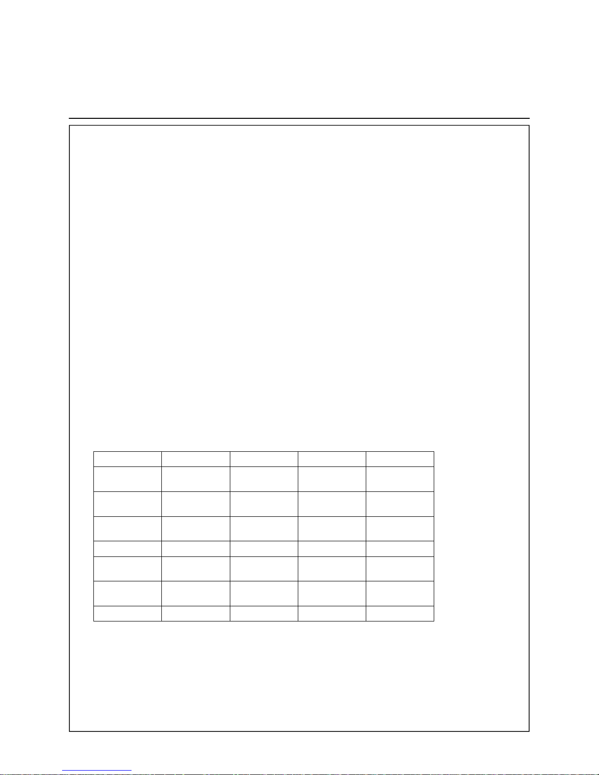
The composition and quality of the
system water directly affect the performance of the overall system and the
life of the boiler.
Normally, mains water with a pH value
of 7-8 can be used for the first filling
and subsequent top-ups, provided that
the water is not strongly corrosive
(chlorine content > 150 mg/l) or is very
hard (>14odH; hardness range IV).
A drinking water analysis can be
requested from the appropriate water
supply company.
If the specific system volume is greater
than 20 litres / kW of heat output (e.g.
through the installation of a hot water
buffer tank), the maximum permitted
chalk deposit must be determined by
the filling and top-up water corresponding to the computation of VDI
guideline 2035. If necessary, the water
must be softened. No chemical anticorrosion substances must be used.
In Austria,
ÖNORM H 5195-1 also applies.
In Switzerland,
SWKI No. 97-1 also applies.
Unknown water quality and replacement systems
Frequently, substances and additives
are in hot water which impact on the
function and life of the burner.
Therefore, either
x heat the old system and then fully
empty before replacing,
or
x carefully rinse the heating system
after replacing. Ideally, the system
should be rinsed directly after the
first heating.
Underfloor heating
For old systems, underfloor heating
systems and if there is problematic
filling water, ELCO recommends fitting
a heat exchanger from the accessories.
Criterion Permissible value Effect of deviation
pH value 7 - 8 Danger of corrosion of boiler components and heating system
Hardness < 14 dH - Increased chalk deposits
- Limited life of boiler
Chlorine content < 150 mg/l Corrosion of alloyed materials
4
Page 5
Product description
Components
Function description
Extent of delivery
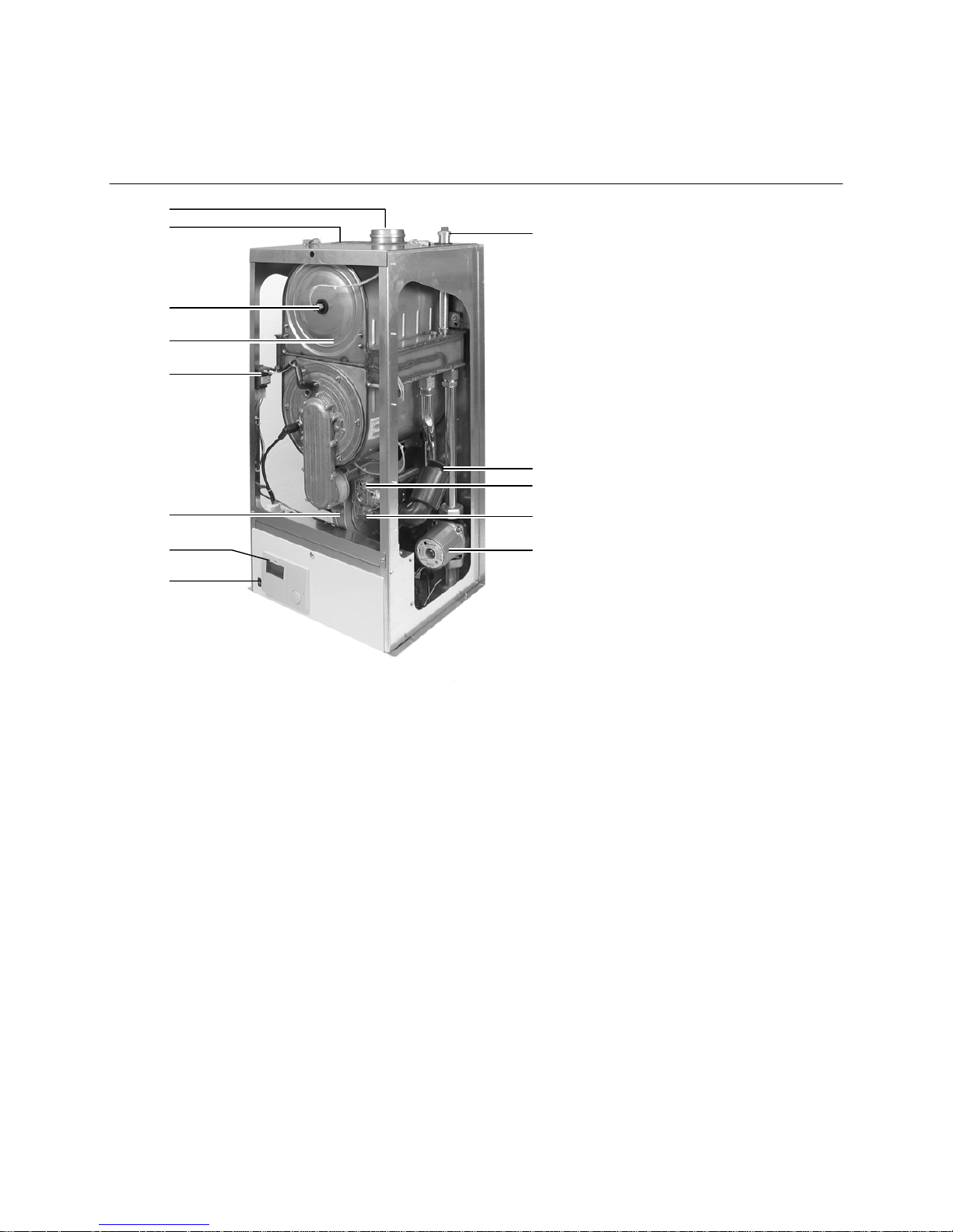
1 Smoke gas exhaust connection
2 Air infeed
3 Smoke gas temperature sensor
4 Heat exchanger
5 Ignition transformer
6 Blower
7 Regulator
8 On / off switch
9 Automatic ventilator
10 Noise insulation (types 65 and 85)
11 Gas valve
12 Venturi tube
13 Boiler pump (outside the boiler on
types 100 and 120)
Product description
The burner RENDAMAX 30 is certified
with CE-0063BO3192 and therefore
corresponds to the following standards
and guidelines:
- DIN EN 677
- EN 60 335
- EN 55 014-1/2
- 90/396/EWG
- 89/336/EWG
- 73/23/EWG
- 92/42/EWG
- DIN EN 483
- DIN EN 297
- DIN EN 656
- The NOx limits required by 1
st
BlmSchV Section 7 (2) are met.
The burner RENDAMAX 30 is a system
with a closed combustion chamber
which is independent of ambient air.
The combustion air enters the device
through an air infeed system. The
burner is used for closed hot water
heating systems. The boiler output is
modulated to the current heating
requirements by the integrated
regulator.
Heat exchanger
The stainless steel heat exchanger is
made from flat spirals and ensures a
transfer of the exhaust gas’s heat to
the boiler water.
The condensation takes place in the
upper section of the heat exchanger.
The condensation is fed down in the
rear section of the heat exchanger.
The control and regulator unit
assumes the function of the automatic
firing device and regulator of the
modulating operation of the boiler and
the hot water preparation. A display
shows the operating status of the
boiler.
The automatic firing device controls
and monitors the safety function
process.
Extent of the delivery
x Burner with circuit diagram
x Documentation
Accessories
x VISTRON tank
x Flue systems
x Neutralisation unit / condensation
treatment
x Pump group
1
2
3
4
5
6
7
8
9
10
11
12
13
5
Page 6
Product description
Circuit diagram
Compact gas fitting
Circuit diagram
The circuit diagram is integrated in the
burner with all the above operating
elements.
The system electronics KM628 offers:
- Management for modulating boiler
regulator
- Hot water preparation
Compact gas fitting
The compact gas fitting works as a gas
safety close valve and as regulator.
The regulator functions as a pneumatic
gas / air difference pressure regulator.
On the gas side, it controls the gas
pressure P
O
in the function of the
combustion air pressure P
L
.
If no air pressure is built up (P
L
= 0),
the gas valve remains closed. The gas/
air pressure ratio and thus also the gas
air volume ratio can be set and then/
remain almost constant over the set
load range.
Technical data
Safety close valve 2, class B/C
Mains power
Type 65-100 AC 24 V
Type 120 AC 230 V
Power consumption
Type 65-100 0,42 A
Type 120 0,09 A
Gas fitting incl. gas filter
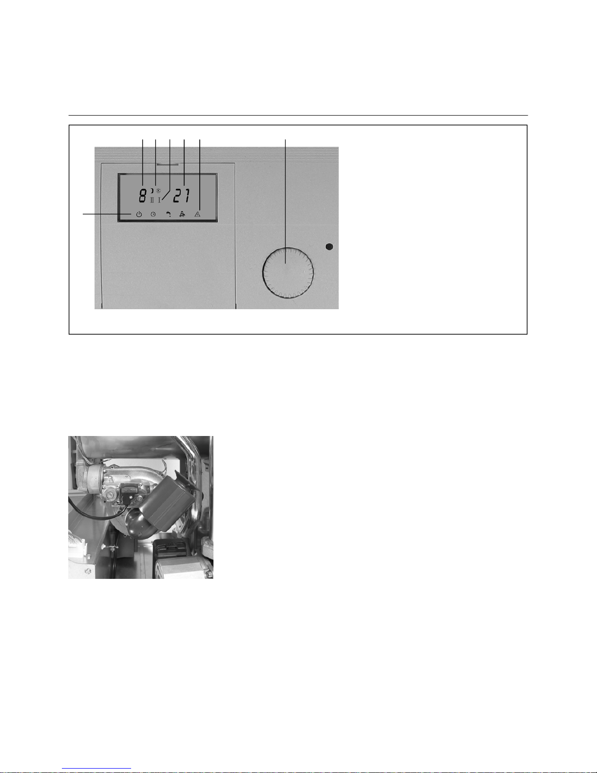
1 Operating type
i Standby
q Automatic operation
F Summer operation
j Chimney sweep operation
2 Operating type selector
3 Fault display E
4 Lead temperature
5 Fault code (blinking)
6 Heating circuit status
C Night operation
B Day operation
(Blinking) Burner on
7 Service status
jI Service status minimum burner
output
jII Service status maximum burner
output
5 6 7 4 3 2
1
6
Page 7
Product description
Technical data
RENDAMAX 30
65 85 100 120
Nominal heat output at 75o / 60o Max/Min kW 58,8/8,3 77,5/15,5 87,2/17,4 108,9/21,8
Nominal heat output at 40
o
/ 30oC kW 65,1/9,2 85,8/17,2 96,5/19,3 120,5/24,1
Nominal heat load kW 60,7/8,6 80,0/16,0 90,0/18,0 112,4/22,5
Standard efficiency 75
o
/ 60oC % 106,3 106,3 106,3 106,3
Standard efficiency 40
o
/ 30oC % 110,1 110,1 110,1 110,1
Operability losses T
K
= 70oC % < 0,3 < 0,3 < 0,3 < 0,3
Max. blower pressure Pa 140 140 140 200
Water content l 6,6 8,4 10,3 12,0
Max. permissible water pressure bar 6 6 6 6
Max. permissible lead temperature °C 90 90 90 90
Condensation volume at 40
o
C / 30oC ca. l/h 9,7 12,8 14,4 18,0
Gas connection value Natural gas
E/H* (Hi=10.9 kWh/m
3
)
m
3
/h 5,6 7,3 8,2 10,3
Natural gas LL (Hi=8.1 kWh/m
3
) m3/h 7,5 9,9 11,1 13,9
Liquid gas propane / butane
(Hi=12.8 kWh/kg)
kg/h 4,7 6,3 7,1 8,8
Min. gas flow pressure Natural gas
Liquid gas
mbar
mbar
20
50
20
50
20
50
20
50
Exhaust gas mass flow for natural gas g/s 31 41 46 58
Exhaust gas temperature net, T
V/TR
75/60 °C 70 70 70 70
Exhaust gas temperature net, T
V/TR
40/30 °C < 55 < 55 < 55 < 55
Gas category II2ELL3P / II2H3P
Exhaust gas value group G61 G61 G61 G61
Construction type - Exhaust gas systems
(B23; C13; C33; C43; C53; C63; C83)
All All All All
Ionisation flow min.
P$
15,0 15,0 15,0 15,0
Connections: Air/exhaust gas pipe (concentric) DN 80/125 110/150 110/150 110/150
Air/exhaust gas pipe (parallel) DN 80/80 100/100 100/100 100/100
Heating lead / heating reflux (inner / outer) DN 25/32 25/32 25/32 25/32
Gas connection DN 20 20 20 20
Condensation pipe connection mm 25 25 25 25
pH value condensation pH 3,0 3,0 3,0 3,0
Electric connection / power consumption 230 V / VAC
(*types 100 and 120 without boiler circuit pump)
W 230 255 130* 215*
CE ID number 0063BO3192
Weight, approx. kg 55 65 80 90
Nominal heat output at 80
o
/60oC kW 59,2 77,8 88,2 109,0
Efficiency at nominal output at 100%, 80
o
/60oC % 97,5 97,3 98 97,7
Efficiency at partial load 30%, 40
o
/30oC % 108,1 108,1 108,1 108,1
Operability losses at 70
o
C average K temp. % < 0,3 < 0,3 < 0,3 < 0,3
Auxiliary energy + integrated boiler circuit pump
(*types 100 and 120 without boiler circuit pump)
W 147 171 83* 137*
7
Page 8
Product description
Dimensions
Type R30/65 R30/85 R30/100 R30/120
B1 mm 120 140 140 140
D mm 80 100 100 100
D1 mm 80 100 100 100
G R
3
/4" R
3
/4" R
3
/4" R
3
/4"
L mm 405 510 560 670
L1 mm 90 90 90 90
W R 1
1
/4" / Rp 1" R 11/4" / Rp 1" R 11/4" / Rp 1" R 11/4" / Rp 1"
8
Page 9

Information about system integration
Chimney
Exhaust
Condensation pipes
Burner technology
In the burner technology, the residual
heat is removed from the exhaust gas
trough cooling and condensation and is
fed to the heating system. In this way,
a higher degree of efficiency is
achieved with low energy consumption.
Information for the chimney
Exhaust systems must be installed in
a shaft corresponding to DIN 18 160 /
Part 1.
Check the exhaust gas pipes before
assembling the burner
Dimensions only apply to the use of
the exhaust gas system made from
polypropylene (PP) DN 110/150.
The low exhaust gas temperatures
required usual exhaust gas pipes
specifically for burners.
Examples:
- Chimneys resistant to moisture
- Condensation-sealed inner dish
- Diameter of the connections
(sleeves) must be considered for
the minimum shaft cross-sections.
Roof heating central
Dependent on ambient air, max. pipe
length 4 m
Exhaust gas is extracted
- via a DIBT (D) or VKF (CH) – ÖTZ
(A) authorised and tested exhaust
pipe
- into the chimney
Pipes and pipe sections
- outside shafts, must be freely
accessible and checkable and
must be protected against frost
- inside shafts, must be rear
ventilated.
Exhaust pipes must be
- moisture resistant
- suitable for exhaust temperatures
below 40
o
C, and
- secure against over-pressure.
Recommendation:
Accessories, exhaust pipe set
Condensation pipes must not be
securely installed. The condensation
is trapped in a funnel and fed into the
sewage system.
Recommendation:
Accessories, neutralisation device
Note worksheet ATV A 251.
Exhaust pipes
Infeed / exhaust system
The applicable local provisions for the
design of the exhaust system must be
observed.
The burner can only be operated with
approved exhaust systems.
On site exhaust systems must be
resistant to moisture, corrosion and
sealed against condensation, and
satisfy static and operating requirements. Unhindered escape of the
exhaust gases must be guaranteed at
the chimney opening (chimneypot is
not recommended).
The connection between chimney and
burner must be fitted with a drop (3%)
so that the condensation escaping
through the exhaust system can flow
back from the exhaust pipe. This
connection should have as few bends
as possible.
Inspection openings must be planned
in the exhaust pipe in accordance with
official requirements. It is possible to
use an exhaust system not dependent
on ambient air.
Exhaust pipes
Horizontal pipes must be avoided in
order to prevent the development of
condensation. It must be ensured that
the various components are connected
to each other with proper seals.
45
o
bends should be used for the
assembly. The vertical parts must be
fixed with straps.
Condensation
The connection of the condensation
pipe (under boiler) must lead to the
exhaust pipe with drop.
It must also be guaranteed that there
is no risk of frost.
Installation example of separate
condensation pipe from the exhaust
gas pipe.
9
Page 10

Assembly
Preparations for the assembly
Installation and distances
Unrestricted access for operation and
maintenance is only possible if the
minimum distances are observed.
Place of installation
Do not install the unit in rooms with
aggressive vapours (e.g. hairspray,
perchloroethylene, tetrachlorocarbon),
large occurrences of dust or high
humidity (e.g. laundry rooms). The
place of assembly must be secure
against frost. If these requirements are
not fulfilled, the warranty for damage
shall lapse.
When assembling the device, please
ensure that no foreign parts (e.g. drill
dust) enter the gas burner. Use covers.
As different requirements apply in
different Bundesländer, consulting the
appropriate authorities and the appropriate district master chimney sweep is
recommended before installation.
Gas connection
The laying of gas pipes and the gas
connection are exclusively the tasks of
the licensed gasfitter. Clean deposits
from the heating network and gas pipes
before connecting the gas burner,
especially order systems.
Please ensure that the gas pipes are
laid free from tension.
Before setting up, check the pipes and
gas connections.
The gas fittings on the burner can be
pressurised to a maximum of 150 mbar.
Minimum distances
10
Page 11

Assembly
Air / exhaust system
Design variations
Ambient air dependent
B23
Ambient air dependent, PPS / Alu white
C33x
Air exhaust system via roof in the same pressure area
Cellar installation
Exhaust-ventilation system to the exhaust chimney
Air-exhaust system via roof
Installation in exhaust chimney not sensitive to moisture
Air exhaust system via roof in the same pressure area
Floor, roof installation
Exhaust, ventilation system via sloping roof or flat roof
C43x
Connection to AZ / LAS (2-speed) multiple configuration on site
C53x
Air infeed and exhaust to outside in different pressure areas on site
C63x
Air, exhaust connection on separately tested and supplied air/exhaust
pipes
Cellar, floor installation
Exhaust, air infeed system through the external wall.
Exhaust trough heat-insulated exhaust pipe or AZ-AW
Exhaust pipe (standing air layer) at the external wall
C83x
Exhaust connection exhaust systems, multiple configuration
(underpressure), combustion air infeed via separate air pipe
on site
Exhaust connection to exhaust system
Multiple configuration (underpressure / overpressure)
Cellar installation
Air supply via installation room
Exhaust system via roof
Minimum shaft cross-section
Shaft rear ventilation according to DIN 18160 for design
B23 (ambient air dependent)
Exhaust pipe ø
110 mm > 168 188
11
Page 12

Assembly
Air / exhaust system
Design variations
Connection to air and exhaust
chimney not sensitive to moisture
C43x (AZ)
The straight air and exhaust pipes
must not be longer than 1.4m when
installing the air and exhaust chimney.
There must not be more than three
90
o
bends.
The air and exhaust chimney AZ must
be tested by the DIBT (German
Institute for Building Technology); the
VKF (Association of Cantonal Fire
Insurance Companies), the ÖTZ and
be approved for burners.
Connection to exhaust chimney not
sensitive to moisture or exhaust
system B23 for ambient air dependent operation
The straight air and exhaust pipes must
not be longer 2m when installing an
exhaust chimney. There must not be
more than three 90
o
bends.
The exhaust chimney must be tested
by the DIBT; the VKF, the ÖTZ and be
approved for burners.
Connection to a combustion air and
exhaust system C63x without a
tested gas furnace
The straight air and exhaust pipes must
not be longer 2m when installing a
combustion air and exhaust system.
There must not be more than three
90
o
bends.
The exhaust system must be tested by
the DIBT; the VKF, the ÖTZ and be
approved for burners. If the combustion
air is taken from the shaft, it must be
free from impurities.
Multiple configuration of exhaust
systems
(not included in the delivery)
The proof of the calculation, design and
function from the manufacturer of the
boiler system must be taken into
consideration in the event of multiple
configurations of the exhaust system.
The local applicable provisions must
be observed for the design of the
exhaust system.
Connection to gas / exhaust system
Only original accessories and parts,
including the offered lubricants for PPS
exhaust systems, must be used for the
concentric air/exhaust gas system.
Gas burners with an air/gas design via
a roof can only be installed in the attic
or in rooms where the ceiling also
forms the roof or there is only the roof
construction over the ceiling.
The air/gas design must not pass
through other rooms.
If a fire-resistance period is demanded
for the ceiling, the pipes for the
combustion air and exhaust system in
the area between the upper edge of
the ceiling and the roof skin must have
a cladding which also has this
fire-resistance period and comprises
non-flammable materials.
If no fire-resistance period is demanded
for the ceiling, the pipes for the
combustion air and exhaust system
from the upper edge of the ceiling to
the roof skin must be in a shaft of
non-flammable, robust materials or in
a metal protective pipe (mechanical
protection).
It must be possible to check exhaust
pipes for free cross-sections. At least
one corresponding revision and / or
test opening must be fitted in the
installation room must have in
accordance with the appropriate district
master chimney sweep.
Exhaust connections are produced
between the sleeve and seal. Sleeves
must always be positioned against the
direction of condensation flow. The
air/gas system must be installed with a
3
o
slope to the burner.
Upon installation, the length to be
calculated of the air and gas system
through the roof must not exceed 4m.
The calculated length of the air and
gas system comprises the straight
pipes and the length of the curved
pipes. A 90
o
bend is treated as 1m and
a 45
o
bend as 0.8m.
In order to prevent mutual impacts on
the air and gas systems through the
roof, we recommend a minimum
distance between the air and gas
systems of 2.5m.
Connection to air and exhaust
chimney not sensitive to moisture
(AZ), exhaust chimney or exhaust
system
Chimneys and exhaust systems must
be approved under building regulations
for furnaces (DIBT approval for “D”,
VKF for “CH and ÖTZ for “A”).
The size is calculated using the
calculation tables according to the
exhaust gas values. There must not be
more than three 90
o
bends. For
chimneys, 0 Pa must be assumed
when calculating the feed pressure.
Temperature [
o
C] Volume flow [m3/h] Mass flow [g/s] Feed pressure [Pa]
RENDAMAX 30 max. / min. max. / min. max. / min. max. / min.
65 70 / 55 113 / 16 31 / 4 140 / 10
85 70 / 55 149 / 30 41 / 8 140 / 15
100 70 / 55 168 / 34 46 / 9 140 / 15
120 70 / 55 209 / 42 58 / 12 200 / 15
12
Page 13

Assembly
Exhaust systems, ambient air dependent
Example: exhaust system
1 Boiler connection
2 T connector with lid 87.5
o
3 Pipe with sleeve
4 Support track
5 Support bend
6 Pipe with sleeve
7 Spacer
8 Furnace shaft cover
10 Revision piece
11 Bend 30
o
13
Page 14

Assembly
Installing the burner
Dismantling / assembling the cover
Removing the boiler covers
x Loosen 2 screws (1) on the front
cover (2)
x Slide the front cover up and
remove
x Loosen the tension fasteners (3) on
the side cover (4)
x Fold the side cover to the right and
left and lift from the clips (5)
x Open the snap fastener (6) on the
front cover plate (7)
x Remove the cover plate
2
1
1
3 3
4
4
5
6
7
1.
2.
4
14
Page 15

Assembly
Burner connection, filling the system
Siphon and condensation trap
x Dismantle the siphon (1), fill and
reassemble
x Connect the condensation trap or
neutralisation equipment
(accessory) with the siphon
Note
The condensation pipe (2) must not be
securely connected to the wastewater
pipe. The condensation must be able
to be drip freely into a funnel.
Filling the system
x Connect the water pipe to the KFE
tap (in the building)
x Open all radiator valves
x Fill cold system to 1 bar
x Check water quality
x Vent pump (if necessary, loosen
blade wheel with screwdriver)
x Fill condensation siphon with water
(approx. 05. l)
x Run pump several times
x After complete venting, fill system
to the final operating pressure
x Close venting screw and remove
filler pipe
Replacement system
x Carefully rinse system
x Check seal at connection points
x Carefully vent system
1 Siphon
2 Condensation connection
3 Cable insert, external cabling
4 Gas connection ¾
5 Lead connection
6 Reflux connection
The connection is only performed
by an authorised expert.
x Connect the gas pipe
x Check seal of pipes
x Connect required exhaust closing
plate (concentric / parallel)
x Insert boiler connector (concentric
or parallel) from above into the
respective opening and press into
the socket. To do this, use the
lubricant suitable for PPS exhaust
pipes
x Connect exhaust collector to the
exhaust system
x Assemble supports
1 2
5 1 4 2 6
3
15
Page 16

Assembly
Electrical installation
General information
Electrical installation and connection
work must only be performed by an
electrician. The VDE/ÖVE/Sev and
EVU provisions and conditions must
be observed.
Mains connection and connection
from building wires
The device is designed for permanent
connection and connection wires NYM
3 x 1.5 mm
2
or H05W-F 3 x 1 mm2.
Burner and switch field are wired.
The mains connection is with a clamp
(3) on the device via a power circuit
envisaged and secured for this.
It must be possible to separate the
burner from the network by suitable
means. Allpolar switches with a
contact opening width > 3 mm or power
protector switch can be used for this.
Mains voltage: 230 V, 50 Hz
Mains connection fuse: 10 A
Power consumption: max. 420 W
Wastewater pump power consumption
Max. switched current KM628
1A / relay
Max. 2.5 A total
The switch field (1) can be folded up
after the securing screw (2) has been
removed.
1 2
3
16
Page 17

Set up
Control measures
Circulating pump
The boiler is fitted with a pump
switch as standard. The pump
is activated when the boiler is
switched on. The pump continues to operate for a few
minutes after the burner
switches off. This period can
be adjusted. The standard
period is 2 minutes.
Type
't 20K
Pump data
Nominal
throughflow
Boiler
resistance
Pump type WILO Pump
setting
Feed
amount
at Q
Residual
feed
amount
at Q
Max.
power consumption*
m
3
/h kPa kPa kPa W
R30/65 2,57 20 RS 25/7 PWM 3/C max. 49 29 132
R30/85 3,38 25 RS 25/7 PWM 3/C max. 40 15 132
R30/100 3,78 28 TOP-S 30/7 *** 3 52 24 195
R30/120 4,70 30 TOP-S 30/7 *** 3 42 12 195
*) Maximum pump power consumption stated in pump position 3
***) Pump optional
Water throughflow speed and pump data R30
17
Page 18

Set up
Control measures
The first set up must be performed
by an authorised expert.
Before set up, the following checks
must generally be performed:
x Check power supply
x Check pressure in the heating
system
x Check pressure at the gas con-
nection
x Check gas pipe seal
x Check perfect assembly of the
exhaust accessories
x Check condensation pipe seal
Minimum circulation quantity / flow
monitoring
It must be guaranteed that the device
has a hydraulic throughflow when
feeding heat. The device is fitted with
a flow safety which monitors the
throughflow. In order to maintain the
minimum throughflow, it is recommended that points or a plate heat
exchanger be fitted (both available as
accessories) or the RENDAMAX 30 is
connected to an open distributor.
Before installation, please note the
following:
x The size of the expansion tank
must be sufficient, see notes on
the water quality, if necessary fill
with softened water.
x The system should be set up
directly after filling in order to rule
our standing air cushions as a
corrosion ovens.
x Chalk deposits in the heating boiler
are avoided by setting up the
device at low system temperatures
and maximum throughflow.
x During revision work, a complete
exchange of the system water
should be avoided. This can be
achieved through partial dams or
reuse of the trapped and filtered
system water.
18
Page 19

Set up
Gas fitting settings
Natural gas settings
Natural gas L / H RENDAMAX 30
Gas connection
pressure
mbar 20
CO
2
max. 65/85/120 %
8,8 r 0,2
CO
2
min. 65/85/120 %
8,2 r 0,2
Min. And max. CO
2
values must
always have a difference of 0.3%.
CO
2
max. 100 %
9,4 r 0,2
CO
2
min. 100 %
8,8 r 0,2
Setting the combustion quality
x Connect the device to the water,
gas and electricity
Because of the different ignition behaviours of natural gas LL and natural
gas E, the gas-air compound must be
adjusted.
x After successful ignition, the
prescribed CO
2
value at full load
can be set by turning the control
screw (2) on the gas valve.
x Set the CO
2
value for low load by
turning the control screw (1) on the
gas fitting
1
Natural gas – liquid gas conversion
The following diaphragms must be
used for conversion to operation with
liquid gas (included with the delivery as
a set):
R30 65: 6,0 mm
R30 85: 6,0 mm
R30 100: 6,8 mm
R30 120: 8,0 mm
Liquid gas settings
Liquid gas RENDAMAX 30
Gas connection
pressure
mbar 50
CO
2
max. 65/85/120 %
9,8 r 0,2
CO
2
min. 65/85/120 %
9,0 r 0,2
Min. And max. CO
2
values must
always have a difference of 0.3%.
CO
2
max. 100 %
10,4 r 0,2
CO
2
min. 100 %
9,6 r 0,2
2
19
Page 20

Set up
Switch field with operating field KM628
Operating functions (flap closed)
When the flap is closed, the desired
operating status can be selected by
turning the knob (2) left or right.
i Standby Boiler not in use, frost protection active
q Automatic operation Boiler in use for heating and hot water user
F Summer operation Boiler in summer operation (only hot water use)
jI Chimney sweep operation, minimum load Boiler in use, minimum load
jII Chimney sweep operation, maximum load Boiler in use, maximum load
20
1 Operating type
i Standby
q Automatic operation
F Summer operation
j Chimney sweep operation
2 Operating type selector
3 Fault display E
4 Lead temperature
5 Fault code (blinking)
6 Heating circuit status
C Night operation
B Day operation
(Blinking) Burner on
7 Service status
jI Service status minimum burner
output
jII Service status maximum burner
output
Page 21

Set up
Display in operating field KM 628
1 Parameter display
P1 Current/set lead temperature
P2 Current/set hot water temperature
*P3 Desired lead temperature
P5 Current outside temperature
P6 Current exhaust temperature
P9 Current burner output
P10 Password
2 Optical interface
3 Reset / program button
4 Alarm LED
5 Parameter selector
6 Operating status outputs
7 Corresponding current measurement
8 Fault / parameter display
9 Operating status inputs
*) P3 desired load (for KKM cascade
manager)
Overview of the symbols
Input symbols
H Flame ionisation in operation
RT Boiler released by external
regulator
Bus Data bus in operation
Output symbols
Main gas valve voltage on
Ignition transformer voltage on
Release of boiler ventilator
Z Boiler pump voltage on
F Hot water load voltage on
Setting the desired lead temperature
for heating operation
Only applicable without weather effect
of 0-5 V signal
x Open flap (the arrow on the lower
side of the LCD display indicates
Parameter 1)
x Press reset / program button (3),
Alarm LED lights up, turn the knob
(5) left or right until the desired
lead temperature appears in the
display
x Press reset / program button (3),
Alarm LED turns off
x Close flap
Setting the desired hot water
temperature for hot water use
Only applicable when using the boiler’s
hot water function
x Open flap)
x Turn the knob to the right until the
arrow on the lower side of the LCD
display indicates Parameter 2
x Press reset / program button (3),
Alarm LED lights up, turn the knob
(5) left or right until the desired hot
water temperature appears in the
display
x Press reset / program button (3),
Alarm LED turns off
x Close flap
Information functions
(flap open)
Information menu
When the flap is open, turning the knob
(5) displays information. There are ten
menus. Using the knob, a selection
can be made. An arrow in the lower
section of the LCD display indicates
which parameter has been selected.
No. Parameter display
P1 Current / set lead temperature
P2 Current / set hot water
temperature
P3 Desired hot water temperature
(desired load for KKM cascade
manager)
P5 Current outside temperature
P6 Current exhaust temperature
P9 Current burner output
P10 Only for trained engineers
21
Page 22

Maintenance and service
Removing device covers
The maintenance work should be
carried out annually. The heat
exchanger does not have to be cleaned
if there is a small amount of dirt, but
must be cleaned at least every two
years.
Maintenance and cleaning work is
only performed by the authorised
expert. He is responsible for correct
maintenance.
Before the maintenance work,
remove the device from the mains
electricity and close the feed and
reflux.
Removing the boiler covers
x Loosen 2 screws (1) on the front
cover (2)
x Slide the front cover up and
remove
x Loosen the tension fasteners (3)
on the side cover (4)
x Fold the side cover to the right and
left and lift from the clips (5)
x Open the snap fastener (6) on the
front cover plate (7)
x Remove the cover plate
2
1
1
3 3
4
4
5
6
7
1.
2.
4
22
Page 23

Maintenance
Cleaning
Cleaning burner and blower
x Visually check the burner (4) and
the blower (2). Dust deposits are
usually blown away and burnt by
the draft from the burner during
normal operation. If there is
additional dirt such as building
dust, a careful cleaning of the
metal material (5) must be
undertaken using a vacuum
cleaner.
x Check seals (6) surrounding the
burner plate and the ceramic fibre
seal (7) for damage and replace if
necessary.
x Check adjustment of electrodes (8)
Cleaning the heat exchanger
x Rinse the heat exchanger (9) with
clean water (remove persistent dirt
with a thin plastic brush and then
rinse)
Dismantling the burner and gas
fitting
x Loosen the electric plug connection
x Loosen 4 screws (1) on the
blower (2)
x Loosen securing screws (3) on the
burner (4)
x Remove the entire burner unit from
the heat exchanger
5
6 7 8
9
3 - 4 mm
5 - 10 mm
1
2
3
4
3
23
Page 24

Maintenance instructions
RENDAMAX 30 Burner
x Measure and record the set
emission values
x Switch off the main heating switch
and secure against reactivation, or
separate the device from the
allpolar mains
x Close the gas tap
x Remove the device covers
x Dismantle the blower, gas valve
and burner unit
x Remove ignition cable. Check
ignition plug for breaks, damp
(damp / wet ignition plugs cause
error messages – replace ignition
plug)
x Check the burner (if necessary
clean with paintbrush / nylon brush
or vacuum cleaner)
x Check blower (if necessary clean
with paintbrush / nylon brush or
vacuum cleaner)
Maintenance and cleaning work is
only performed by the authorised
expert. He is are responsible for
correct maintenance.
The maintenance work should be
carried out annually. The heat
exchanger does not have to be cleaned
if there is a small amount of dirt, but
must be cleaned at least every two
years.
x Remove furnace chamber
insulation
x Rinse heat exchanger with clean
water (remove persistent dirt with
a thin plastic brush and then rinse)
x Clean siphon and refill with water
before reassembly
x Check seal of all connections to
condensation-carrying parts.
Remove any escaped conden sation or other moisture
x Check securing screws, replace if
necessary
x Check system pressure, expansion
tank and safety valve.
x Dismantled seals for gas and
water-carrying parts must be
replaced for new ones when
reassembling. This is the case, in
particular, for O-rings on the gas
valve and all burner seals
x Reassemble device ready for use
x Open gas pipe and check seal
x Switch on main heating switch
x Carry out function control with
emission measurements
x If necessary, readjust values
according to factory requirements.
24
Page 25

List of error messages
Error messages displayed on KM 628
Error messages
The E symbol and an error code are
displayed in the event of an error.
Before correcting the error, the cause
of the error must be found and
remedied.
The operating signal fails if an error
occurs twice within six minutes (error
code is shown on the display, with “3”
above) or if there is an error which is
active for longer than six minutes.
1. Maximum thermostat (STB) has
reacted
The lead temperature has exceeded its
set value. Wait until the lead temperature is below the set value for at least
one minute, then unlock the safety
function by pressing the reset button.
2/3. Blocking entrance has been
interrupted
An external safety, connected to the
clamps (ST 9.3-9.4) has reacted.
Check and test this safety.
4. Flame disruption
When starting combustion, no flame
was detected during the set safety
period. If the corresponding programming has been undertaken, a new start
is possible.
5. Flames reduce during operation
While the burner is in use, the
respective ionisation flow was below
1 µA.
Check and unlock this safety function
by pressing the reset button.
6. Maximum temperature monitor
(STW) has reacted
The lead temperature has exceeded
the value set for it or the water flow is
too weak.
7. Maximum smoke gas thermostat
has activated
The smoke gas temperature has
exceeded 100
oC.
Remedy the fault
and activate Reset.
11. Wrong flame signal
An ionisation flow exceeding 1 µA has
been measured while the burner is in
use.
Remedy the fault and activate Reset.
12. Defective lead temperature
sensor
The measured resistance of the
temperature sensor is outside the
range between -10 and +126
oC.
Remedy the fault and press Reset.
13. Defective smoke gas temperature
sensor / locked entrance has been
interrupted
The measured resistance of the smoke
gas sensor is outside the range
between -10 and +126
oC.
Remedy the fault and press Reset.
An external retainer, connected to the
clamps (1 – 3) has reacted. Check and
repair this retainer.
14. Defective water sensor
The measured resistance of the water
sensor is outside the range between
-39 and +110
oC.
Remedy the fault and press Reset.
15. Defective external sensor
The measured resistance of the
external sensor is outside the range
between -39 and +110
oC.
Remedy the fault and press Reset.
20/21. Error in the gas valve control
After the burner has been switched off,
no ionisation flow bas been measured
for 5 seconds, which was greater than
1 µA. Remedy the fault and press
Reset.
24. Wrong minimum blower speed
When rinsing, a specific minimum
bower speed is not achieved. Remedy
the fault and press Reset.
25. Defective maximum blower
speed
A specific maximum blower speed has
not been undercut for the ignition.
Remedy the fault and press Reset.
26. Defective blower speed at stop
When the blower is switched off, the
selected speed is too high
(300 revolutions / minute).
Remedy the fault and press Reset.
30. CRC error in the control
parameters
An Eeprom error has occurred in the
stored control parameters. Check and
change this parameter set.
31. CRC error in the safety-relevant
parameters
An Eeprom error has occurred in the
stored safety-relevant parameters.
Check and change this parameter set.
32. Faults in the low voltage power
supply
The low voltage power supply is too
small or the fuse is defective. Remedy
the fault and press Reset.
x.y. internal error
An internal error has been detected in
the electronics. Check and remedy
this error.
25
Page 26

26
Notes
Page 27

Notes
27
Page 28

ELCO GmbH
D - 64546 Mörfelden-Walldorf
ELCO Austria GmbH
A - 2544 Leobersdorf
ELCOTHERM AG
CH - 7324 Vilters
ELCO-Rendamax B.V.
NL - 1410 AB Naarden
ELCO Belgium n.v./s.a.
B - 1731 Zellik
Service:
 Loading...