

Page 1
R600
Operation and Installation manual
for authorized technicians only
Betriebsanleitung
für die autorisierte Fachkraft
Bedienings- en Installatiehandleiding
alleen voor bevoegde vakmensen
Notice d’installation et d’emploi
réservée à l’usage des techniciens agréés
Istruzioni per l'uso
solo per il tecnico autorizzato
07/2010 DOC3070 / 12099579
Page 2

Page 3
Operation and Installation manual
for authorized technicians only
R 600
07/2010 DOC3070 / 12099579
Page 4

Contents
2
Contents .................................................................. 2
Safety General regulations ................................... 3
Application ................................................. 3
Norms and regulations .............................. 3
Construction Layout of boiler .......................................... 4
Operating principle .................................... 4
Technical data .................................................................. 5
Extent of delivery Standard boiler .......................................... 7
Accessories ............................................... 7
Installation Boiler transport .......................................... 8
Removing the casing ................................. 9
Boiler installation ....................................... 10
Connecting the boiler ................................ 11
Commissioning Water and hydraulic system ...................... 13
Gas supply ................................................ 14
Condensate connection ............................. 14
Flue and air intake connections ................. 14
Prepare boiler for first startup .................... 15
Combustion analysis ................................. 16
Check water flow ...................................... 17
Check functionality of safety devices ........ 18
Gas tightness check .................................. 18
Boiler shut down ........................................ 18
Commissioning protocol ............................ 19
Operating instructions Controls .................................................... 20
Display / Programming .............................. 21
Overview of main functions ....................... 22
Maintenance Checklist .................................................... 23
Replacing the electrodes ........................... 23
Cleaning the condensate receptacle ......... 24
Cleaning and refilling the syphon .............. 24
Inspection of combustion chamber ............ 24
Water pressure and quality ....................... 25
Water flow rate .......................................... 25
Combustion analysis ................................. 25
Gas pressure ............................................. 25
Gas tightness check .................................. 25
Safety devices ........................................... 25
Maintenance protocol ................................ 26
Lockouts .................................................................. 27
Sensor values .................................................................. 30
Declaration of Conformity .................................................................. 31
Page 5

Safety
General regulations
Application
Norms and regulations
3
General regulations
This documentation contains important
information, which is a base for safe
and reliable installation, commissioning
and operation of the R600 boiler. All
activities described in this document
may only be excecuted by authorized
companies.
Changes to this document may be effected without prior notice. We accept
no obligation to adapt previously delivered products to incorporate such
changes.
Only original spare parts may be used
when replacing components on the
boiler, otherwise warranty will be void.
Application
The R600 boiler may be used for heating and hot water production purposes
only. The boiler should be connected to
closed systems with a maximum temperature of 100ºC (high limit temperature), maximum setpoint temperature is
90ºC.
Norms and regulations
When installing and operating the
boiler, all applicable norms (european
and local) should be fulfilled:
Local building regulations for install-
ing combustion air and flue gas systems;
Regulation for connecting the boiler to
the electrical appliance;
Regulations for connecting the boiler
to the local gas network;
Norms and regulations according to
safety equipment for heating systems;
Any additional local laws/regulations
with regard to installing and operating
heating systems.
Additional national standards
Germany:
RAL - UZ 61 / DIN 4702-8
Switzerland:
SVGW
EKAS-Form. 1942: Flüssiggas-
Richtlinie Teil 2
Vorschriften der kantonalen Instanzen
(z.B. Feuerpoilizeivorschriften)
Netherlands:
GASKEUR BASIS
GASKEUR SV
GASKEUR HR107
Belgium:
HR TOP
The R600 boiler is CE approved and
applies to the following European
standards:
92 / 42 / EEC
Boiler efficiency directive
2009 / 142 / EEC
Gas appliance directive
73 / 23 / EEC
Low voltage directive
2004 / 108 / EEC
EMC directive
EN 656
Gas-fired central heating boilers –
Type B boilers of nominal heat input
exceeding 70 kW but not exceeding
300 kW
EN 15420
Gas-fired central heating boilers Type C boilers of nominal heat input
exceeding 70 kW, but not exceeding
1000 kW
EN 15417
Gas-fired central heating boilers Specific requirements for condensing
boilers with a nominal heat input
greater than 70 kW but not exceeding
1000 kW
EN 13836
Gas fired central heating boilers Type B boilers of nominal heat input
exceeding 300 kW, but not exceeding
1000 kW
EN 15502-1
Gas-fired central heating boilers Part 1: General requirements and
tests
EN 55014-1 (2000)
Electromagnetic compatibility - Requirements for household appliances,
electric tools and similar apparatus Part 1: Emission
EN 55014-2 (1997)
Electromagnetic compatibility - Requirements for household appliances,
electric tools and similar apparatus Part 2: Immunity - Product family
standard
EN 61000-3-2 (2000)
Electromagnetic compatibility (EMC) Part 3-2: Limits - Limits for harmonic
current emissions (equipment input
current 16 A per phase)
EN 61000-3-3 (2001)
Electromagnetic compatibility (EMC) Part 3-3: Limitation of voltage
changes, voltage fluctuations and
flicker in public low-voltage supply
systems, for equipment with rated
current 16 A per phase and not subject to conditional connection
EN 60335-1 (2002)
Household and similar electrical appliances - Safety - Part 1: General requirements
EN 60335-2-102 (2006)
Household an similar electrical
appliances: Particular requirements
for gas, oil and solid-fuel burning appliances having electrical connections
Page 6
Construction
Layout of boiler
Operating principle
4
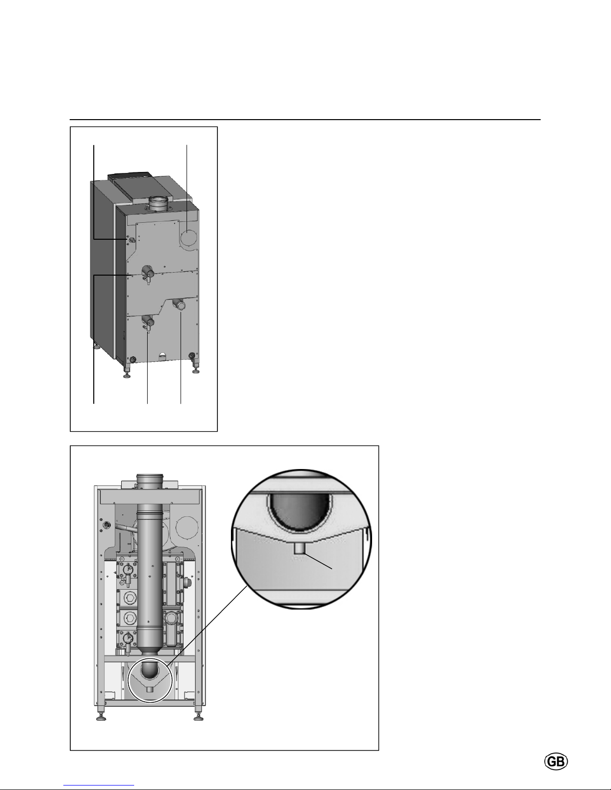
Layout of boiler
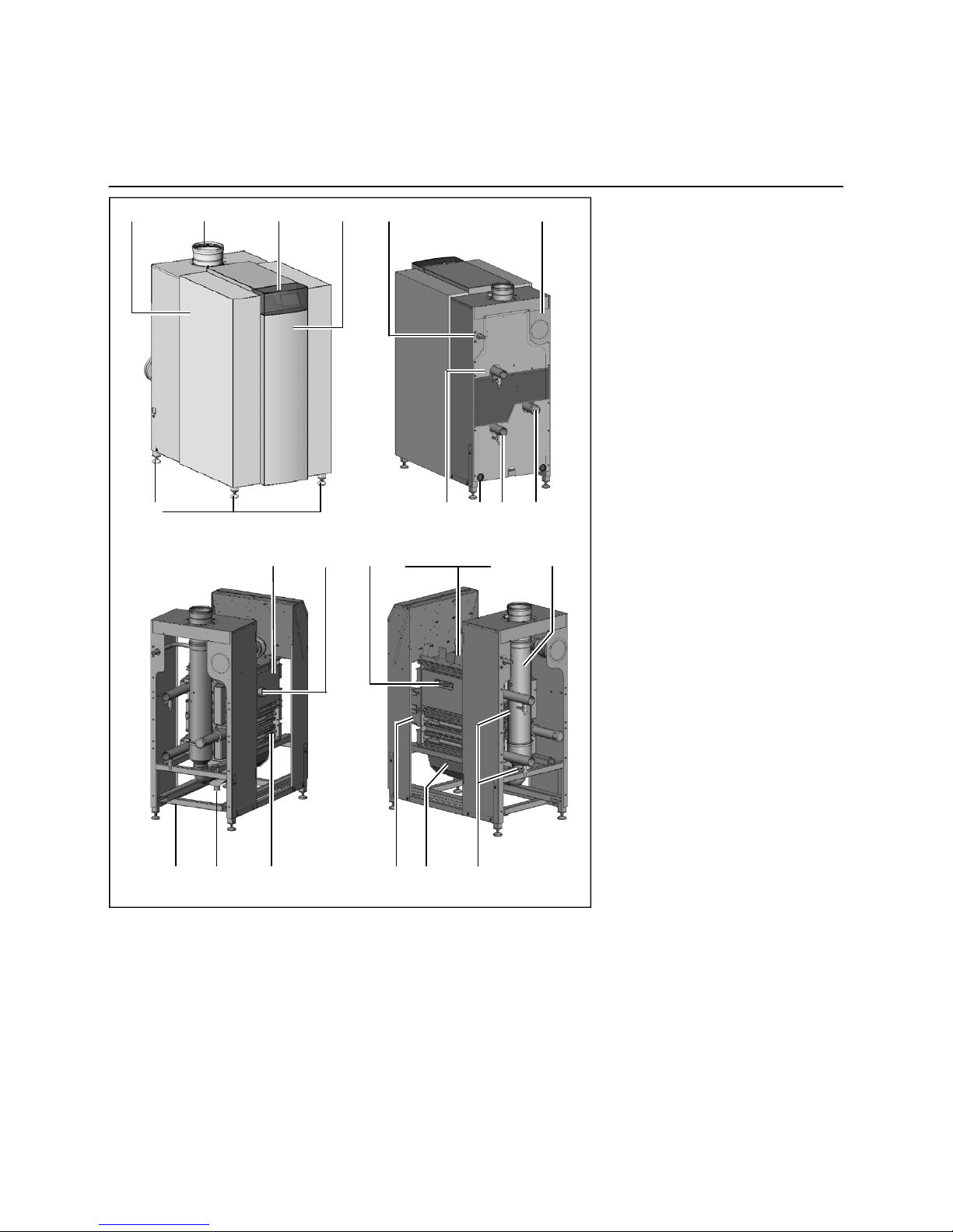
The R600 boiler consists of the following main components:
1 Casing
2 Front panel
3 Adjustable feet
4 Control panel (below cover)
5 Flue gas connection
6 Air intake connection
(under casing)
7 Gas connection
8 Flow water connection
9 Return water connection
10 2nd (hot) return water connection
(for split system use)
11 Filling/draining valve
12 Electrical input connections
13 Frame
14 Burner/1st heat exchanger
assembly
15 2nd/3rd heat exchanger assembly
16 Water headers
17 Condensate receptacle
18 Whirlwind gas/air mixing system
19 Fan
20 Gas valve
21 Gas pressure switch
22 Inspection opening
23 Ignition and ionisation electrodes
24 Syphon
25 Removable flue gas adapter
Operating principle
The R600 is a fully modulating boiler.
The control unit of the boiler adapts the
modulation ratio automatically to the
heat demand requested by the system.
This is done by controlling the speed of
the fan. As a result, the Whirlwind mixing system will adapt the gas ratio to
the chosen fan speed, in order to maintain the best possible combustion figures and therewith the best efficiency.
The flue gases created by the combustion are transported downwards
through the boiler and leave at the back
side into the chimney connection.
The LMS14 control unit can control the
boiler operation based on:
Boiler control (stand alone operation);
weather compensated operation
(with optional outdoor sensor);
with 0-10V external influence
(temperature or capacity) from a building management system.
The return water from the system enters the boiler in the lower section,
where is the lowest flue gas temperature in the boiler. In this section condensation takes place. The water is
being transported upwards through the
boiler, in order to leave the boiler at the
top (burner) section. The cross flow
working principle (water up, flue gas
down) ensures the most efficient combustion results.
1 5 4 2 7 6
3 8 12 9 10
14 22 23 18, 19, 20, 21 25
13 24 15 16 17 11
Page 7
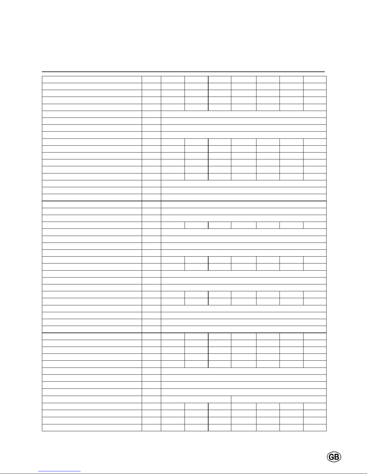
Technical data
5
R601 R602 R603 R604 R605 R606 R607
Nominal heat output at 80/60ºC max/min*
kW 142.1/23.3 190.1/39.5 237.2/39.5 285.2/39.5 380.2/76.6 475.3/76.6 539.0/76.6
Nominal heat output at 75/60ºC max/min*
kW 142.2/23.5 190.3/39.5 237.4/39.5 285.5/39.5 380.6/76.6 475.8/76.6 539.6/76.6
Nominal heat output at 40/30ºC max/min*
kW 150.7/26.7 201.6/45.2 251.4/45.1 302.3/45.2 403.1/87.7 503.9/87.7 571.5/87.7
Nominal heat input Hi max/min*
kW 145.0/24.5 194.0/41.5 242.0/41.5 291.0/41.5 388.0/80.5 485.0/80.5 550.0/80.5
Efficiency at 80/60ºC
% 98.0
Efficiency at 40/30ºC % 103.9
Annual efficiency (NNG 75/60ºC)
% 106.8
Annual efficiency (NNG 40/30ºC)
% 110.4
Standstill losses (T
water
= 70ºC) % 0.21 0.18 0.17 0.16 0.15 0.14 0.13
Max. condensate flow
l/h 11 15 19 22 30 37 42
Gas consumption H-gas max/min (10,9 kWh/m
3
) m3/h 13.3/2.3 17.8/3.8 22.2/3.8 26.7/3.8 35.6/7.4 44.5/7.4 50.5/7.4
Gas consumption L-gas max/min (8,34 kWh/m
3
) m3/h 17.4/2.9 23.2/5.0 29.0/5.0 34.9/5.0 46.5/9.7 58.2/9.7 66.0/9.7
Gas consumption LL-gas max/min (8,34 kWh/m
3
) m3/h 17.4/2.9 23.2/5.8 29.0/5.8 34.9/5.8 46.5/11.2 58.2/11.2 66.0/11.2
Gas consumption LPG. max/min (12,8 kWh/kg)
kg/h 11.3/1.9 15.2/3.2 18.9/3.2 22.7/3.2 30.3/6.3 37.9/6.3 43.0/6.3
Gas pressure H-gas
mbar 20
Gas pressure L/LL-gas
mbar 25
Gas pressure LPG
mbar 30/50
Maximum gas pressure
mbar 100
Flue gas temperature at 80/60ºC max/min
ºC 78/61
Flue gas temperature at 40/30ºC max/min
ºC 56/30
Flue gas quantity max/min*
m
3
/h 238/40 318/69 397/69 477/69 636/134 795/134 901/134
CO
2
level natural gas H/E/L/LL max/min % 10.2/9.4
CO
2
level liguid gas P max/min % 11.9/10.0
NOx level max/min
mg/kWh 35/15
CO level max/min
mg/kWh 14/8
Max. permissible flue resistance max/min
Pa 160/10 160/10 200/10 200/10 200/10 250/10 250/10
Water volume
l 27 31 35 61 68 75 82
Water pressure max/min
bar 8/1
Max. water temperature (High limit thermostat)
ºC 100
Maximum temperature setpoint
ºC 90
Nominal water flow at dT=20K
m
3
/h 6.1 8.1 10.2 12.2 16.3 20.4 23.1
Hydraulic resistance at nominal water flow
kPa 10 18 28 15 27 42 55
Electrical connection
V 230/400
Frequency
Hz 50
Mains connection fuse
A 16
IP class
- IP20
Power consumption boiler max/min (excl. pump)
W 158/43 200/35 230/35 260/35 470/61 650/61 770/61
Power consumption 3-step pump (optional)
W 170/90 190/120 380/210 380/210 530/300 720/380 1150/600
Power consumption speed controlled pump (opt)
W 180/10 180/10 435/25 435/25 450/25 800/35 800/35
Power consumption bypass pump (optional)
W 55/35 85/65 170/90 170/90 190/120 460/225 470/280
Weight (empty)
kg 295 345 400 465 535 590 650
Noise level at 1 meter distance dB(A) 59
Ionisation current minimum µA 6
PH value condensate - 3.2
CE certification code - CE-0063BS3840
Water connections
- R2" DN65 PN16
Gas connection
- R3/4" R1" R1" R1" R1.1/2" R1.1/2" R1.1/2"
Flue gas connection
mm 150 150 200 200 250 250 250
Air intake connection (for room sealed use)
mm 130 150 150 150 200 200 200
Condensate connection
mm 40 40 40 40 40 40 40
* min load on gasses H/L/LPG. For type R602-R607 on gasses LL-Gas min value is 15% higher.
Page 8
Technical data
6
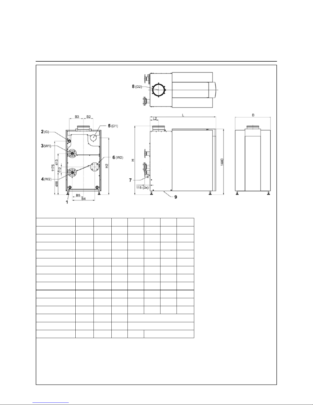
Dimension R601 R602 R603 R604 R605 R606 R607
L mm 1105 1260 1470 1220 1435 1585 1735
L2 mm 127.5 127.5 137.5 137.5 187.5 187.5 187.5
H mm 1480 1480 1500 1500 1500 1500 1500
H2 mm 1120 1130 1130 1150 1245 1245 1245
B mm 670 670 670 770 770 770 770
B2 mm 225 235 235 235 215 215 215
B3 mm 260 260 260 310 310 310 310
B4 mm 260 260 260 490 490 490 490
B5 mm 130 130 130 245 245 245 245
D1 mm (Diam.) 130 150 150 150 200 200 200
D2 mm (Diam.) 150 150 200 200 250 250 250
W1 R" / DN R2" R2" R2" DN65 PN16
W2 R" / DN R2" R2" R2" DN65 PN16
G R R 3/4" R 1" R 1" R 1" R 1 1/2"
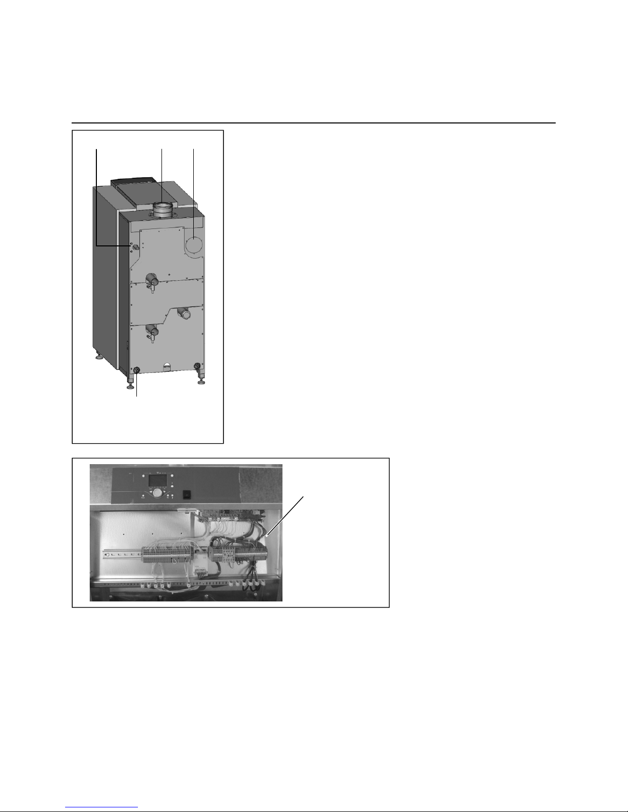
1 Electrical connections
2 Gas supply
3 Water supply
4 Water return (Cold)
5 Air Intake (under casing)
6 Water 2nd return (Hot)
7 Boiler water drain valve 1/2"
8 Flue gas Outlet
9 Condensate drain
flexible hose 25mm diam.
Page 9
Extent of delivery
Standard boiler
Accessories
7
Standard boiler
A boiler delivery package contains the
following components:
The above accessories are specially
designed for the R600 boiler and therewith easy to install (plug and play). By
choosing a combination of the kits mentioned above, you can create your own
complete system solution. Ask your
supplier for more detailed information.
Extension module AVS75 for heating
zone control or external gas valve
and/or room fan control.
For each boiler a maximum of 3
AVS75 modules (2x heating zone, 1x
ext. gas valve / room fan) can be integrated in the boiler;
Additional RVS63 heating zone con-
troller, when controlling more than 2
zones (incl. wall hung box, all necessary sensors and sockets and connection material for bus communication).
Component Pcs. Package
Boiler fully assembled and tested 1 Mounted on wooden blocks with wooden border,
sealed in PE foil
Adjustable feet 4 Mounted on frame of the boiler
Syphon for condensate connection 1 Cardboard box on top of heatexchanger
(under casing)
Conversion kit for natural gas L and propane incl. instruction 1 Cardboard box on top of heatexchanger
(under casing)
Operation and Installation manual 1 Map attached to back panel of the boiler
Spare parts list 1 Map attached to back panel of the boiler
Wiring diagram 1 Map attached to back panel of the boiler
Accessories
Additional to the boiler, the following
accessories can be ordered:
Standard 3-step pump incl. connec-
tion kit;
Speed controlled pump incl. connec-
tion kit;
Safety valve, manometer and de-
aerator (3,4,5 or 6 bar) incl. connection kit;
2x max. water pressure switch and 1
external high limit thermostat incl.
connection kit;
Gas filter incl. connection kit;
Max. gas pressure switch;
External high limit thermostat incl.
connection kit;
Gas valve leakage tester (not possi-
ble for R601);
Controlled bypass (incl. pump) incl.
connection kit;
Plate heat exchanger (dT=10K/15K or
dT=20K) incl. connection kit;
Low velocity header, suitable for
dT=10K/15K and dT=20K incl. connection kit;
Duo header for connecting 2 boilers
in cascade (excl. connection kit);
Page 10
Installation
Boiler transport
8
Boiler transport
The R600 boiler will be supplied as a
complete unit being fully assembled
and pre-tested. The maximum width is
670mm for models R601-R603 and
770mm for models R604-R607, which
makes it possible to transport all models through a normal door in one piece. The boiler can be transported with a
pallet truck, entering either from the
front or from the side.
Whenever necessary, the boiler can be
dismantled into smaller parts for easier
transport inside the building. The table
below shows the main dismantled parts
with their weight and dimensions.
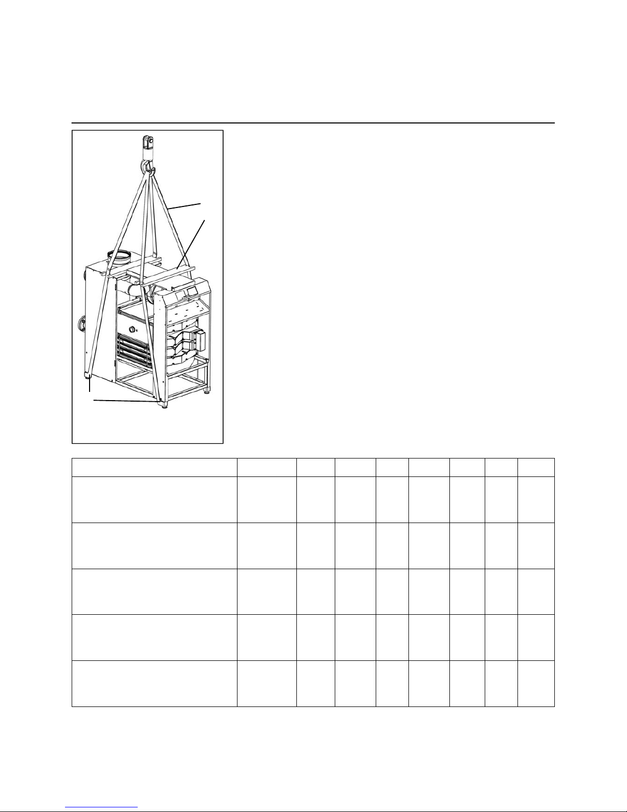
When the boiler has to be transported
with a crane, it is necessary to remove
the casing before connecting the boiler
to the crane. Always connect the crane
to the frame of the boiler by using
straps.
Component R601 R602 R603 R604 R605 R606 R607
Burner/1st heat exchanger assembly Weight [kg]
Length [mm]
Width [mm]
Height [mm]
86
735
400
321
100
885
400
321
112
1035
400
321
135
735
680
321
158
885
680
321
181
1035
680
321
198
1185
680
321
2nd/3rd heat exchanger assembly Weight [kg]
Length [mm]
Width [mm]
Height [mm]
90
735
400
244
103
885
400
244
116
1035
400
244
150
735
680
244
170
885
680
244
198
1035
680
244
219
1185
680
244
Condensate receptacle
Weight [kg]
Length [mm]
Width [mm]
Height [mm]
7
589
385
225
9
739
385
225
10
889
385
225
11
589
665
225
12
739
665
225
13
889
665
225
15
1039
665
225
Frame
Weight [kg]
Length [mm]
Width [mm]
Height [mm]
15
990
624
335
16
1140
624
335
17
1350
624
335
17
1100
724
335
18
1320
724
335
19
1470
724
335
21
1620
724
335
Front U-frame with electronic board Weight [kg]
Length [mm]
Width [mm]
Height [mm]
11
628
1304
202
11
628
1304
202
11
628
1304
202
12
728
1304
202
12
728
1304
202
12
728
1304
202
12
728
1304
202
1 Hoisting belt (4x)
2 Wooden retaining beam (2x)
3 Hoisting belt position (4x)
1
2
3
Page 11
Installation
Removing the casing
9
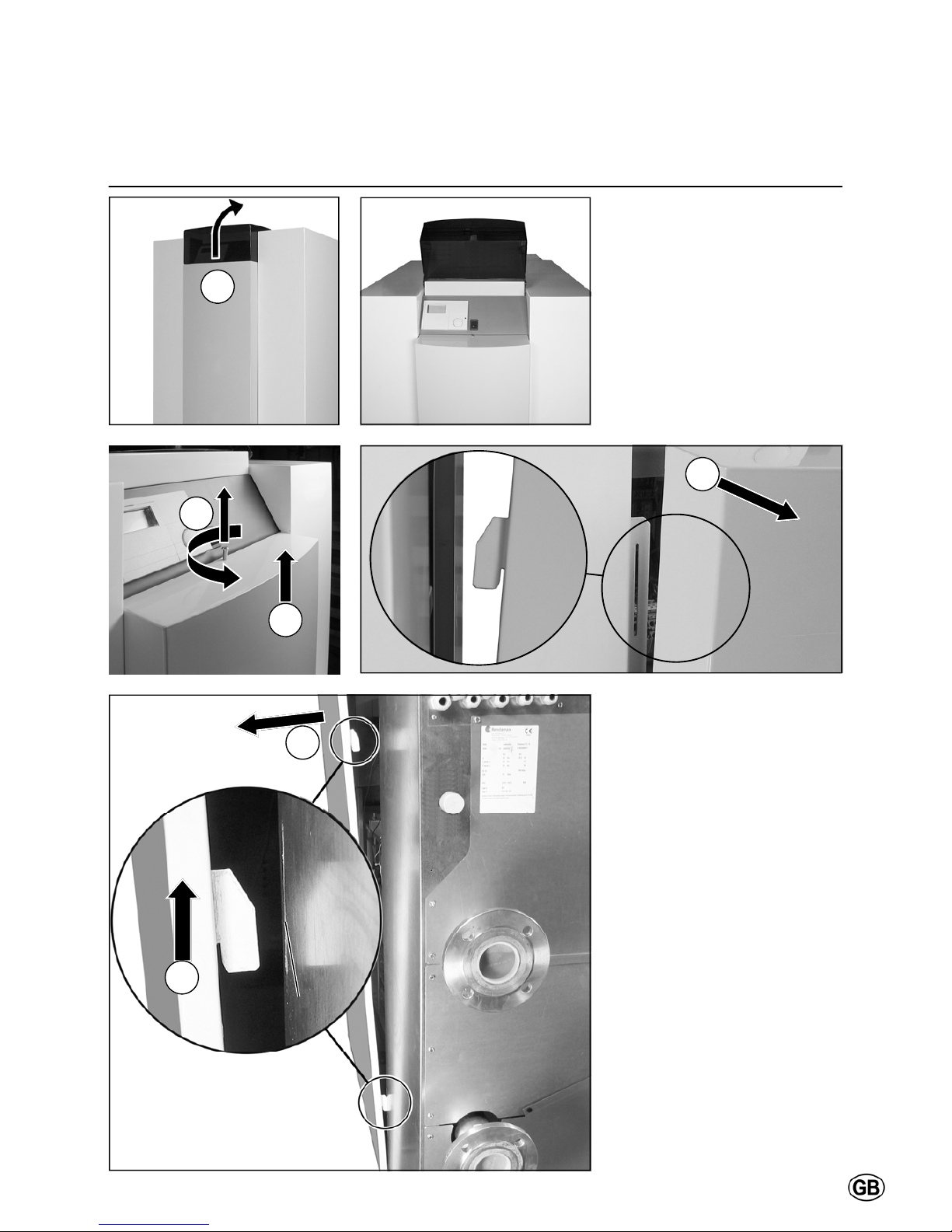
Boiler transport
Remove the casing before transporting
the boiler, in order to avoid damage to
the casing parts during transportation.
Removing the casing is done as follows:
1.
2.
3.
4.
5.
6.
Page 12
Installation
Boiler installation
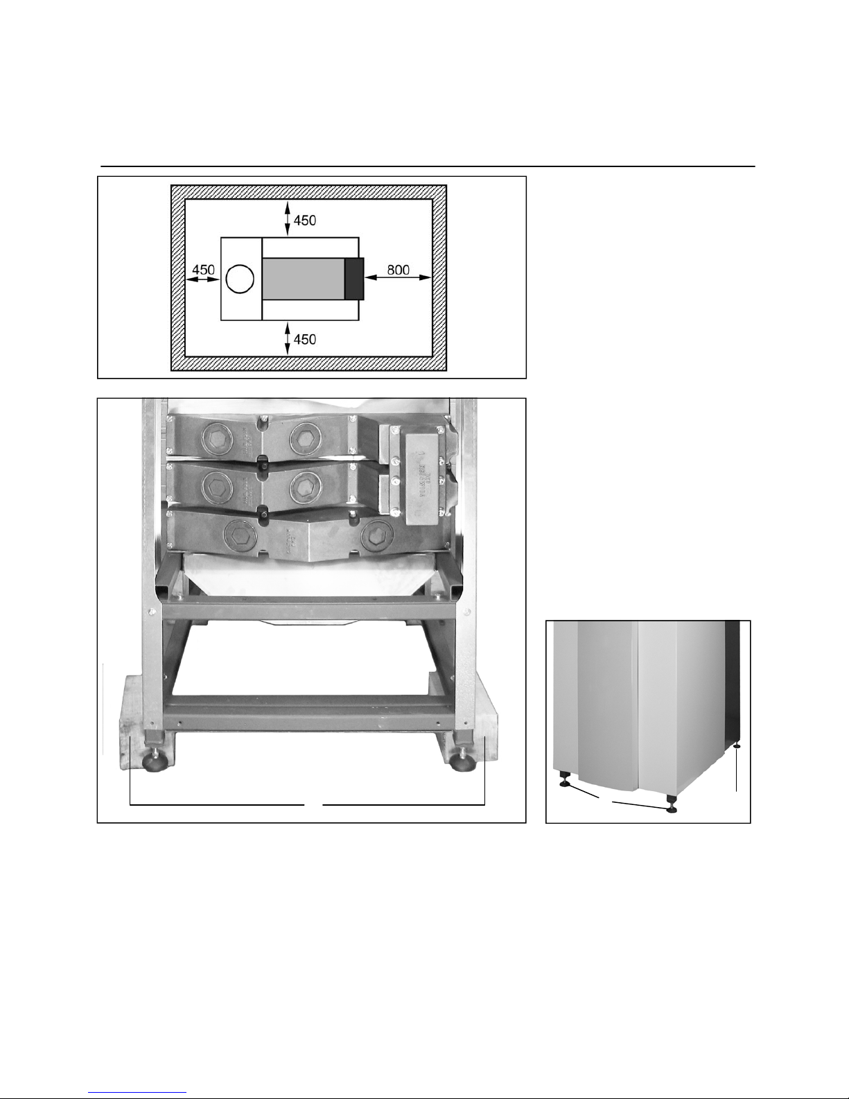
Boiler installation
The boiler should be positioned in a
frost-proof boiler room. If the boiler
room is on the roof, the boiler itself may
never be the highest point of the installation.
When positioning the boiler, please
note the recommended minimum clearance in the picture. When the boiler is
positioned with less free space, maintenance activities will be more difficult.
Once the boiler is in the correct position, the wooden blocks (1) should be
removed and the adjustable feet (2)
(with vibration absorption dampers)
should be adjusted to the right height.
Water and gas connections should be
done after mounting the feet, as they
affect the exact height of all connections.
10
1
2 2
Page 13
Installation
Connecting the boiler
11
Connecting the boiler
This chapter will explain how to make
all connections to the boiler with regard
to:
Hydraulic connections
Condensate drain connection
Gas connection
Flue gas connection
Air intake connection
(under casing)
Electrical connection
The boiler should always be connected
in such a way, that the system applies
to all relevant standards and regulations (European, national and local). It’s
the responsibility of the installer to ensure that all standards and regulations
are respected.
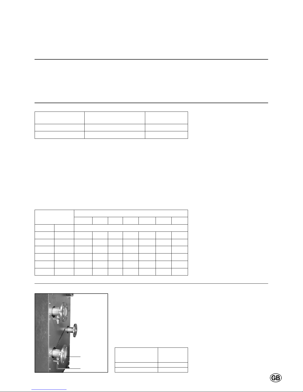
Hydraulic connections
The boiler should always be connected
in such a way, that water flow through
the boiler can be ensured at all times.
Connect the flow (4) and return (5) connection of the system tension free to
the boiler connections. If the boiler is
used in a system with two return circuits, the common return becomes the
low temperature return, the 2nd return
connection (6) is the high temperature
return (remove cap/flange before connecting).
The (optional) accessory kit with safety
valve, manometer and deaerator
should be mounted on the flow connection (4) of the boiler, before connecting
to the system.
The (optional) pump kit should be
mounted directly to the return connection (5) of the boiler, before connecting
to the system.
Condensate connection (8)
After filling with water, the syphon
(included in delivery) should be installed to the connection at the bottom
of the condensate receptacle. Lead the
hose under the frame at the back of the
boiler and connect it to the draining
system in the boiler room. The connection to the draining system should always be done with an open connection,
in order to avoid a flooding of the boiler
in case of a blocked drain.
8
1 3
4 5 6
Page 14
Installation
Connecting the boiler
12
Gas connection (1)
The gas connection must be made by
an authorized installer in accordance
with the applicable national and local
standards and regulations.
Connect the gas line from the system
tension free to the gas connection (1) of
the boiler. A gas cock should be mounted directly behind the boiler.
A gas filter can be mounted directly on
the gas connection of the boiler.
Flue gas connection (7)
Regulations for the construction of flue
gas systems are very different for each
country. It should be ensured that all
national regulations with regard to flue
gas systems are respected.
Connect the flue gas system to the flue
gas connection (7) of the boiler, use
fluegas systems with seamless connections only. It’s not necessary to make a
separate condensate drain for the flue
gas system, as the condensate will be
drained via the syphon of the boiler.
Please note the following issues:
It’s recommended to use stainless
steel or PPS fluegas systems
The diameter of the flue gas system
must be chosen by calculation according to the national regulations
Construct the flue gas system as
short as possible (for maximum
length see planner documentation)
Construct horizonal ways with a mini-
mum angle of 3º
Air intake connection (3)
The air intake can be connected in case of room sealed installation. The cover (3) must be disassembled in order
to connect the air intake piping to the
connector inside the boiler. The diameter should be calculated according to
the national regulations, together with
the flue gas system. The total resistance of both systems should never overcome the maximum permissible resistance of the fan inside the boiler (see
also chapter: Technical data).
Electrical connection
The electrical connection must be made by an authorized installer in
accordance with the applicable national
and local standards and regulations.
For the power supply it’s necessary to
use a mains isolator switch with a contact opening of at least 3 mm
within the boiler room. This switch can
be used to switch off the power supply
for maintenance purposes.
All cables should be lead through the
cable glant (2) from the back of the
boiler boiler into the electro panel
(11).
Connect all wires to the terminals
according to the wiring diagram of the
boiler (enclosed in map attached to
back panel of the boiler).
1 7 3
2
11
Page 15
Commissioning
Water and hydraulic system
13
Water quality
The system should be filled with water
with a PH value between 8,0 and 9,5.
The chloride value of the water should
not exceed 50 mg/l. Entry of oxygene
by diffusion should be prevented at all
times. Damage to the heat exchanger
because of oxygene diffusion will not
be taken under warranty.
Boiler output
[kW]
Max. sum of alkaline earths
[mol/m3]
Max. total hardness
[dºH]
50 - 200 2.0 11.2
200 - 600 1.5 8.4
Concentrate
Ca(HCO3)2
Capacity of installation Q (kW)
150 200 250 300 400 500 600
mol/m
3
dºH Maximum water (re)fill volume V
max
[m3]
≤0.5 ≤2.8 - - - - - - -
1.0 5.6 - - - - - - -
1.5 8.4 3 4 5 6 8 10 12
2.0 11.2 3 4 5 6 6.3 7.8 9.4
2.5 14.0 1.9 2.5 3.1 3.8 5.0 6.3 7.5
≥3.0 ≥16.8 1.6 2.1 2.6 3.1 4.2 5.2 6.3
Minimum operating
pressure
[bar]
Flow tempe-
rature
[ºC]
> 1.5 90
> 1.0 80
Water pressure
Open the valves to the system. Check
the water pressure in the system. If the
water pressure is too low (see table
below), increase the pressure up to at
least the minimum required water
pressure in the table.
Filling can be done via the fill and drain
valve (2) on the return connection (1) of
the boiler.
1
2
Hydraulic system
Check if the boiler is hydraulically connected to the system in such way, that
water flow can be secured at all times
during burner operation. The water flow
is supervised by the water flow switch
in the boiler and a lack of flow will lead
to a direct burner stop and lockout of
the boiler.
Commissioning of the boiler should be
carried out by authorized personnel
only. Failure to respect this condition
makes the guarantee void. A protocol
of the commissioning should be filled
out (see end of this chapter for example
of commissioning protocol).
This chapter explains the commissioning of the boiler with the standard boiler controller. When an additional system controller is installed, please refer
to its manual for commissioning the
controller.
In installations with higher water volumes, it’s necessary to respect the maximum filling and additional volumes with
corresponding hardness values as stated in the german VDI2035 standard. In
the table you can find the nominal values for filling and additional water for
the R600 according to the the VDI2035.
The table at the left gives an indication
of the relation between the water quality and the maximum water filling volume during the lifetime of the boiler.
Consult the original text of the VDI2035
for more detailed information.
Page 16

Commissioning
Gas supply
Condensate connection
Flue and air intake connections
14
Gas supply
Check the gas supply connection to the
boiler for tightness. If any leakage is
found, reseal the leakage before starting the boiler!
Remove any air between the gas valve
and the gas line. This can be done at
the test point (1) at the gas pressure
switch. Don’t forget to close the test
point afterwards!
Check the gas type and values with the
local gas company, in order to know for
which gas type the boiler should be
commissioned.
Consult the conversion kit instruction if
the boiler is to be installed with natural
gas L or LPG.
Condensate connection
Remove the syphon (2) from the condensate connection. Fill it with water
and place it back in the original position. Make sure the syphon is filled
before starting the boiler, in
order to prevent flue gases discharging through the condensate connection!
Flue and air intake connections
Check whether the flue and air intake
systems are made according to the
national and local regulations. Installations which don’t comply with the regulations, are not allowed to be commissioned.
Make sure that all connections are free.
The size of flue gas and air intake connections may not be reduced.
1
2
Page 17

Commissioning
Prepare boiler for first startup
15
1
M
H
B C D E F
I
L
G
A
Legend:
A On/off switch
B Return (ESC)
C Room temperature control
D Confirmation (OK)
E Manual mode
F Chimney sweeper mode
G Info mode
H Reset button
I Operation mode heating zone(s)
L Display
M Operation mode DHW
Preparation for first startup
Open the gas supply;
Enable the power supply to the boiler;
Switch on the boiler with the on/off
switch (1);
Make sure the boiler is in standby
mode (K);
Check the pump operation: make
sure the pump runs in the right
direction;
Release all air from the pump motor.
It‘s recommended to put the boiler on
50% load after the first startup, as this
is the best starting point to do a proper
combustion analysis. This can be done
with the following procedure:
Push button I >3 Sek, the boiler goes
into controller Stopp mode.
Push the Info button (G), the actual
boiler load (%) appears in the display;
Choose „set up“ (confirm with OK
button), now the boiler load can be
changed by rotating the wheel (C)
and confirming the 50% setting with
the OK button.
After checking the combustion values
(see next page), the controller Stopp
mode can be stopped by pushing the
control mode button (I) >3 Sek.
Page 18

Commissioning
Combustion analysis
16
Combustion settings
for natural gas G20 / G25
R601-R607
CO
2, max
% 10.2 ± 0.2
CO
max
ppm < 30
Combustion settings
for LPG G31
Convert boiler before operation
(see coversion kit instruction)
R601-R607
CO
2, max
% 11.9 ± 0.2
CO
max
ppm < 30
Combustion check at full load
Start the boiler in controller stop mode
and go to 50% load. Now the boiler
operates at 50% load. Allow the boiler
to stabilise the combustion for 3
minutes. Then increase the boiler load
step by step up to 100%. Check the
gas pressure on the inlet of the gas
valve while increa-sing the boiler load:
the gas pressure should never go
below the minimum required value
see technical data. Set the minimum
gas pressure switch (1) at 75% of the
required gas pressure.
Check the combustion settings via the
test point in the chimney connection(3).
If necessary, correct the settings with
the flat adjustment screw on the outlet
of the gas valve (2).
Combustion settings
for natural gas G20 / G25
R601-R607
CO
2, min
% 9.4 ± 0.2
CO
min
ppm < 30
Combustion settings
for LPG
G31
Convert boiler before operation
(see coversion kit instruction)
R601-R607
CO
2, min
% 10.0 ± 0.2
CO
min
ppm < 30
Combustion check at minimum load
Switch the boiler to minimum load (0%).
Check the combustion settings the
same way as described for full load. If
necessary, correct the settings with the
allen key adjustment screw on either
side of the gas valve (4).
Combustion check at 50% load
An additional reference check of combustion values at 50% load is recommended in order to check if the gas
valve is set in such way, that the modulating behaviour is normal. The CO
2
value should be in between the settings
of full load and minumum load. CO
value should be equal to full load and
minimum load values.
Make sure that the boiler is set to automatic operation and controller stop mode is disabled after the combustion test
is finished.
2
4
R601
R602 - R607
1
2
4
3
Page 19

Commissioning
Check water flow
17
q
actual
= (∆T
nominal
/ ∆T
measured
) * q
nominal
[m3/h]
Water flow data
R601 R602 R603 R604 R605 R606 R607
Nominal flow rate [m
3
/h] 6.1 8.1 10.2 12.2 16.3 20.4 23.1
∆T at nominal flow rate [ºC] 20
∆p at nominal flow rate [kPa] 10 18 28 15 27 42 55
Check water flow
The water flow through the boiler can
be checked with two different methods
shown below.
∆T measurement
Check the temperature difference over
the boiler (∆T flow-return) when the
boiler is running on 100% load. The
nominal ∆T is 20K and must be at least
between 15K and 25K for secure boiler
operation. An indication of the actual
flow rate can be found with the following calculation (see table below for
nominal data):
q
actual
= √(∆p
measured
/ ∆p
nominal
) * q
nominal
[m3/h]
∆p measurement
Check the pressure difference over the
boiler (∆p flow-return) when the boiler
pump is running (burner on is not required). The nominal ∆p for each boiler
type can be found in the table below,
actual ∆p must be within:
0.35*Δp
nom
≤ ∆P ≤ 1.75*∆p
nom
. An
indication of the actual flow rate can be
found with the following calculation (see
table below for nominal data):
Page 20

Commissioning
Check functionality of safety devices
Gas tightness check
Boiler shut down
18
5
4
6
Flow temperature sensor (1)
Disconnect the plug from the sensor
while the boiler is switched on. This
should result in a lockout no. 20.
The lockout should disappear as soon
as the plug is placed back in position,
the boiler will restart.
Return temperature sensor (2)
Disconnect the plug from the sensor
while the boiler is switched on. This
should result in a lockout no. 40.
The lockout should disappear as soon
as the plug is placed back in position,
the boiler will restart.
Flue gas temperature sensor (3)
Disconnect the plug from the sensor
while the boiler is switched on. This
should result in a lockout no. 28.
The lockout should disappear as soon
as the plug is placed back in position,
the boiler will restart.
.
Minimum gas pressure switch (5)
Close the gas cock when the boiler is in
standby position (
K). Open the test
point on the gas line (4) while measuring the gas pressure on the test point
of the gas pressure switch (5).
The boiler will go in lockout no. 2 when
the switch off setting is achieved. Close
both test points and open the gas cock.
Check functionality of safety devices
All safety devices have to be checked
on good functioning. Safety devices on
a standard boiler are a water flow temperature sensor, fluegas temperature
sensor, water flow switch minumum
gas pressure switch and ionisation
electrode. These devices can be
checked as described below.
Ionisation electrode (6)
Remove electrical connection from the
ionisation electrode while the boiler is
running, the boiler will go in lockout no.
128. The boiler will try to restart. With
the electrical connection removed, the
restart will result in lockout no. 133.
When the connection is already
mounted, the restart will be successful.
Measuring the ionisation current can
be done by mounting a multi-meter (set
to µA) in between the ionisation electrode and its electrical connection. The
ionisation current should always be
above 1.2 µA, in normal conditions it
will be 6 µA and above.
Gas tightness check
Check the gas tightness of all sealed
connections with an approved soap or
electronic gas analyzer, for example:
Test points
Bolt connections
Gaskets of mixing system, etc.
Boiler shut down
When the boiler will not be used for
longer periods, shut down the boiler by
following procedure:
Switch the boiler in standby operation
(K)
Switch off the boiler with the on/off
switch (7)
Disable power supply to the boiler by
deactivating the mains isolator switch
in the boiler room
Close the gas supply to the boiler.
7
1 2 3
Page 21

Commissioning
Commissioning protocol
19
Commissioning Protocol R600
Project
Boiler type Project
Serial number Address
Year City
Nominal load (Hi) [kW] Date
Nominal output (Hi) [kW] Engineer
System
Water pressure [bar] Installati-
on:
Roof top
Water pH [-] Ground floor
Water hardness [dºH] Basement
Water chloride [mg/l] Other: .........................
Water ∆T full load [ºC] Hydrau-
lics:
Low velocity header
Water ∆p
boiler
[kPa] Plated heat exchanger
Water flow [m
3
/h] Bypass boiler
Pump setting [-] Other: .........................
Safety devices
High limit setting [ºC] Water flow sensor checked
Temp. limiter setting [ºC] Fluegas sensor checked
Min. gas pressure switch setting [mbar] Water flow switch checked
Ignition time burner [sec]
Combustion analysis
100% load 50% load Min. load
Gas consumption [m
3
/h] [m3/h] [m3/h]
Gas pressure [mbar] [mbar] [mbar]
CO
2
[%] [%] [%]
O
2
[%] [%] [%]
CO [ppm] [ppm] [ppm]
NOx [ppm] [ppm] [ppm]
T
atmospheric
[ºC] [ºC] [ºC]
T
fluegas
[ºC] [ºC] [ºC]
T
water, flow
[ºC] [ºC] [ºC]
T
water, return
[ºC] [ºC] [ºC]
Ionisation current [µA] [µA] [µA]
p
fan
[mbar] [mbar] [mbar]
p
top panel
[mbar] [mbar] [mbar]
p
combustion chamber
[mbar] [mbar] [mbar]
Remarks
Page 22

Operating instructions
Controls
20
Confirmation (OK) (D)
Return (ESC) (B)
These buttons are used for programming in combination with the wheel.
By pressing the ESC button it‘s possible
to go back one level, changed values
are not taken over by the controller.
By pressing the OK button it‘s possible
to arrive in the next level or confirm
changed values.
Manual mode (E)
This button is used for switching the
boiler into manual mode. In manual
mode all pumps will run and the mixing
valves are no longer controlled, the burner setpoint is 60°C (indicated by spanner symbol).
On/off switch (A)
Position 0:
Boiler and connected electrical components are no powered. Frost protection
is not secured.
Position I
The boiler and connected electrical
components are powered and standby
for operation.
Operation mode DHW (M)
For switching on the DHW operation
(indication in display below DHW symbol)
Operation mode heating zone(s) (I)
For setting 4 different heating modes:
Auto (clock): Automatic operation by
time programm
Comfort (sun): 24/7 heating in comfort
mode
Reduction (moon): 24/7 heating in reduced mode
Standby: heating off, frost protection
activated.
Display (L)
Info mode (G)
Display possibility of following info
without influence on boiler control:
temperatures, operation mode
Heating / DHW, error code.
Room temperature control (C)
for changing room comfort tempe-
rature
for changing settings when pro-
gramming.
Deaeration mode (E)
By pressing the manual mode button
longer than 3 seconds, the automatic
hydraulic deaeration is activated. During
deaeration the system is put in standby
mode
The pumps are switched on and off for
several times.
After deaeration, the boiler automatically
returns to normal operation.
Chimney sweeper mode (F)
Used for combustion analysis. By pressing the button once again, or automatically after 15 minutes, the chimney sweeper mode will be deactivated (indicated
by spanner symbol).
Reset button (H)
By shortly pressing the reset button a
burner lockout can be cancelled.
M
H
B C D E F
I
L
G
A
Legend:
A On/off switch
B Return (ESC)
C Room temperature control
D Confirmation (OK)
E Manual mode
F Chimney sweeper mode
G Info mode
H Reset button
I Operation mode heating zone(s)
L Display
M Operation mode DHW
Page 23

21
Operating instructions
Display / Programming
- gewünschtes Menü
auswählen
- mit Taste OK bestätigen
- mit Taste ESC zurück
zur Grundanzeige
- gewünschte Benutzer-Ebene auswählen
- mit Taste OK bestätigen
- gewünschtes Menü auswählen
- mit Taste OK bestätigen
- mit Taste ESC zurück zur Grundanzeige
DHW mode selection
Heating operation mode selection
(Controller Stopp mode when
pressing > 3 sec.)
Display
Info button
Confirm
Manual mode
(Deaeration mode when pressing
> 3 sec.)
Chimney sweeper mode
Enduser
- choose menu
- confirm with OK button
- choose parameter
- confirm with OK button
- change value + - with wheel
- confirm with OK button
- return to main menu with ESC button
Commissioning Expert
- choose user level
- confirm with OK button
- choose menu
- confirm with OK button
- choose parameter
- confirm with OK button
- change value + - with wheel
- confirm with OK button
- return to main menu with ESC button
Programming
Select
(turn left/right)
Quit menu
Reset
Press OK (1x)
Press OK (1x)
Press INFO (4 sec.)
Default mode
(buttons)
Heating to comfort setpoint Info level activated
Heating to reduced setpoint Programming activated
Heating for frost protection setpoint Heating temporarily
switched off
Process running – please weit ECO function active
Burner operating (only oil / gas boiler)
Error messages
Info level activated
Programming activated
Heating temporarily switched off
ECO function active
Holiday function active
Reference to heating circuit
Maintenance / special operation
Parameter number
Page 24

22
Operating instructions
Overview of main functions
Button Action Procedure Display / Function
Set room temperature
Zone 1 and zone 2
Actuate wheel left/right
Turn wheel
Confirm with OK button
or wait 5 sec.
or press
Comfort setpoint with blinking temperature
Blinking temperature in 0,5 °C steps from 10 to 30 °C
Comfort setpoint saved
Comfort setpoint cancelled
- after 3 sec. Main menu appears
Set room temperature for
zone 1 or zone 2
Zone 2 independent from zone 1
Actuate wheel left/right
Confirm with OK button
Actuate wheel left/right
Confirm with OK button
or wait 5 sec.
or press
Choose heating zone
Heating zone is chosen
Blinking temperature in 0,5 °C steps from 10 to 30 °C
Comfort setpoint saved
Comfort setpoint cancelled
- after 3 sec. Main menu appears
Switch on /off DHW operation
Press button DHW mode on / off
(see indication below DHW symbol)
- On: DHW mode by time programm
- Off: no DHW operation
- Safety functions activated
Change heating operation
mode
Factory setting
Press button 1x
Press button 1x again
Press button 1x again
Automatic mode on, with:
- Heating by time programm
- Temperature setpoint by heating programm
- Safety functions activated
- Summer/Winter automatic switching activated
- ECO-functions activated
(see indication below operation symbol)
Continuous COMFORT heating on, with:
- Heating without time programm by comfort setpoint
- Safety functions activated
Continuous REDUCED heating on, with:
- Heating without time programm by reduced setpoint
- Safety functions activated
- Summer/Winter automatic switching activated
- ECO-functions activated
Safety mode on, with:
- Heating off
- Temperature by frost protection
- Safety functions activated
Controller Stop mode Press button > 3 sec.
Press button > 3 sec. again
304: Controller Stopp mode insert setpoint
after 3 sec. Main menu appears
Info display
Press button 1x
Press button 1x again
Press button 1x again
…..
Press button 1x
INFO Segment displayed
- Status Boiler - room temperature
- room temperature minimum
- Status DHW - room temperature maximum
- Status zone 1 - outside temperature
- Status zone 2 - outside temperature minimum
- outside temperature maximum
- Time / Date - DHW temperature 1
- Error indication - Boiler temperature
- Maintenance indication - Flow temperature
(Info display depends on configuration)
Back to main menu; INFO Segment disappears
Operation by manual
setpoint
Change factory setting
boiler temperature
Press button 1x
Press button
Press button
Turn wheel -/+
Press button
Press button
Press button
Manual mode on (spanner symbol appears)
- Haeting by fixed setpoint
(factory setting = 60 °C)
301: Manual mode insert setpoint?
blinking temperature
set value
Status boiler
Manual mode off (spanner symbol disappears)
Deaeration Press button > 3 sec.
Press button > 3 sec. again
312: Deaeration on
Deaeration off
Activate chimney sweeper
mode
Press button (< 3 sec.)
Press button again (< 3 sec.)
Chimney sweeper mode on
Chimney sweeper mode off
Temporary reduction of
reduced temperature on
QAA75
Press button
Press button again
Heating by reduced setpoint
Heating by comfort setpoint
RESET Reset button Press button (< 3 sec.)
Press button again > 3 sec.
Boiler manually blocked, no release
Boiler released, Alarm symbol disappears
= confirmation
= cancel, return to main
menu
Page 25

Maintenance
Checklist
Replacing the electrodes
23
Maintenance of the boiler should be
carried out by authorized personnel
only.
In order to ensure continued good and
safe operation of the boiler, it should be
inspected at least once per year. A
maintenance protocol should be filled
out (see end of this chapter for example
of maintenance protocol).
Checklist
The following activities must be carried
out, see following paragraphs for an
extensive description of the main activities:
Replace the ignition and ionisation
electrodes;
Clean the condensate receptacle;
Clean and refill the syphon;
Inspect the combustion chamber,
clean if necessary;
Check the water pressure of the sys-
tem;
Check the water quality of the system
water as well as supply water;
Check the water flow rate through the
boiler;
Check/correct the combustion values
at full and mimimum load with a combustion analyzer;
Check the gas pressure to the boiler;
Check the tightness of all sealed con-
nections and test points;
Check the functionality of all safety
devices;
Fill out a maintenance protocol.
Replacing the electrodes
The electrodes are positioned on the
right hand side of the boiler. Replace
the ignition elektrode (1) and ionisation
eclectrode (2) as shown on the picture.
2
1
Page 26

Maintenance
Cleaning the condensate receptacle
Cleaning and refilling the syphon
Inspection of combustion chamber
24
5
6
7
Cleaning the condensate receptacle
Disconnect the plug of the fluegas
temperature sensor (1);
Remove the internal fluegas pipe (2)
of the boiler in order to create access
to the condensate receptacle;
Clean the receptacle (3);
Mount the fluegas pipe back in positi-
on when the cleaning is finished;
Connect the plug of the fluegas tem-
perature sensor.
Inspection of combustion chamber
The inspection opening is positioned on
the left hand side of the boiler.
Remove the radiation panel (5) from
the heat exchanger;
Remove the cover (6) from the in-
spection opening;
Inspect the combustion chamber (7),
clean if necessary;
Mount the cover and radiation panel
back in original position.
Cleaning and refilling the syphon
Remove the syphon (4) from the con-
densate connection;
Clean and fill it with fresh water;
Mount the syphon back in the original
position.
4
1
3
2
Page 27

Maintenance
25
Water pressure and quality
Check if the water pressure and quality
meet the requirements. Consult the
chapter “commissioning: water and
hydraulic system” for more detailed
information.
Water flow rate
Check if the water flow rate through the
boiler is within the limits. Consult the
chapter “commissioning: check water
flow” for more detailed information.
Combustion analysis
Check the combustion at full load and
minumum load, correct the settings if
necessary. An additional reference
check at 50% load is recommended.
Consult the chapter “commissioning:
combustion analysis” for more detailed
information.
Gas pressure
Check the dynamic pressure of the gas
supply to the boiler, when the boiler is
running at full load. In case of a boiler
cascade, all boilers should be running
at full load. See technical data for required values.
Gas tightness check
Check the tightness of all sealed connections with an approved soap or
electronic analyzer, for example:
Test points;
Bolt connections;
Gaskets of mixing system, etc.
Safety devices
Check the functionality and the settings
of all safety devices connected. Consult
the chapter “commissioning: Check
functionality of safety devices” for more
detailed information.
Page 28

Maintenance
Maintenance Protocol
26
Maintenance Protocol R600
Project
Boiler type Project
Serial number Address
Year City
Nominal load (Hi) [kW] Date
Nominal output (Hi) [kW] Engineer
System
Water pressure [bar]
Water pH [-]
Water hardness [dºH]
Water chloride [mg/l]
Water ∆T full load [ºC]
Water ∆p
boiler
[kPa]
Water flow [m
3
/h]
Pump setting [-]
Safety devices
High limit setting [ºC] Water flow sensor checked
Temp. limiter setting [ºC] Fluegas sensor checked
Min. gas pressure switch setting [mbar] Water flow switch checked
Ignition time burner [sec]
Combustion analysis
100% load 50% load Min. load
Gas consumption [m
3
/h] [m3/h] [m3/h]
Gas pressure [mbar] [mbar] [mbar]
CO
2
[%] [%] [%]
O2 [%] [%] [%]
CO [ppm] [ppm] [ppm]
NOx [ppm] [ppm] [ppm]
T
atmospheric
[ºC] [ºC] [ºC]
T
fluegas
[ºC] [ºC] [ºC]
T
water, flow
[ºC] [ºC] [ºC]
T
water, return
[ºC] [ºC] [ºC]
Ionisation current [µA] [µA] [µA]
p
fan
[mbar] [mbar] [mbar]
p
top panel
[mbar] [mbar] [mbar]
p
combustion chamber
[mbar] [mbar] [mbar]
Remarks
Page 29

27
In case of a lockout, a warning symbol ( ) and a flashing error code appears on the display. The cause of a fault should first
be determined and eliminated before the boiler is being reset. The table below shows all possible lockouts with indication of
possible cause.
Lockouts
Error
code
Description of error
0 No error
10 Outside temperature sensor error
20 Boiler temperature 1 sensor error
26 Common flow temperature sensor error
28 Flue gas temperature sensor error
30 Flow temperature 1 sensor error
32 Flow temperature 2 sensor error
38 Flow temperature primary controller sensor error
40 Return temperature 1 sensor error
46 Return temperature cascade sensor error
47 Common return temperature sensor error
50 DHW temperature 1 sensor error
52 DHW temperature 2 sensor error
54 DHW primary controller sensor error
57 DHW circulation temperature sensor error
60 Room temperature 1 sensor error
65 Room temperature 2 sensor error
70 Buffer storage tank temperature 1 sensor error
71 Buffer storage tank temperature 2 sensor error
72 Buffer storage tank temperature 3 sensor error
73 Collector temperature 1 sensor error
74 Collector temperature 2 sensor error
82 LPB address collision
83 BSB wire short-circuit
84 BSB address collision
85 BSB RF communication error
91 EEPROM error lockout information
98 Extension module 1 error (collective error)
99 Extension module 2 error (collective error)
100 2 clocktime masters (LPB)
102 Clocktime master without reserve (LPB)
103 Communication error
105 Maintenance message
109 Boiler temperature supervision
110 STB lockout
111 TW cutout
121 Flow temperature 1 (HC1) supervision
122
Flow temperature 2 (HC2) supervision
125 Pump supervision error
126 DHW charging supervision
127 Legionella temperature not reached
128 Loss of flame during operation
129 Fan error or LP error
130
Flue gas temperature limit exceeded
131
Burner fault
132 GP or LP error
133 No flame during safety time
146 Configuration error collective message
Page 30

Lockouts
28
Error
code
Description of error
151 Internal error
152 Parameterization error
153 Unit manually locked
160 Fan error
162 LP error, does not close
164 Error heating circuit flow switch
166 LP error, does not open
171 Alarm contact H1 or H4 active
172 Alarm contact H2 (EM1, EM2 or EM3) or H5 active
173 Alarm contact H6 active
174 Alarm contact H3 or H7 active
178 Limit thermostat heating circuit 1
179 Limit thermostat heating circuit 2
183 Unit in parameterization mode
193 Pump supervision error after flame on
216 Fault boiler
217 Fault sensor
241 Flow sensor solar sensor error
242 Return sensor solar sensor error
243 Swimming pool temperature sensor error
270 Limit function
317 Mains frequency outside permissible range
320 DHW charging temperature sensor error
324 BX same sensors
325 BX / extension module same sensors
326 BX / mixing group same sensors
327 Extension module same function
328 Mixing group same finction
329 Extension module / mixing group same function
330 Sensor BX1 no function
331 Sensor BX2 no function
332 Sensor BX3 no function
333 Sensor BX4 no function
334 Sensor BX5 no function
335 Sensor BX21 no function (EM1, EM2 or EM3)
336 Sensor BX22 no function (EM1, EM2 or EM3)
337 Sensor BX1 no function
338 Sensor BX12 no function
339 Collector pump Q5 not available
340 Collector pump Q16 not available
341 Solar Collector sensor B6 not available
342 DHW sensor B31 not available
343 Solar integration not available
344 Solar controlling element buffer K8 not available
345 Solar controlling element swimming pool K18 not available
346 Solid fuel boiler pump Q10 not available
347 Solid fuel boiler comparison sensor not available
348 Solid fuel boiler address error
Page 31

29
Lockouts
Error
code
Description of error
349 Buffer return valve Y15 not available
350 Puffer address sensor
351 Primary controller / system pump address error
352 Pressureless header address error
353 Common flow sensor B10 not available
371 Flow temperature 3 (heating circuit 3) supervision
372 Limit thermostat heating circuit 3
373 Extension module 3 error (collective error)
386 Fan speed has lost valid range
388 DHW error no function
426 Feedback flue gas damper
427 Configuration flue gas damper
431 Sensor primary heat exchanger
432 Functional earth not connected
433 Temperature primary heat exchanger to high
Page 32

Sensor values
The diagrams show the sensor values
for all boiler sensors and optional sensors available in accessory kits.
The diagrams contain average values,
as all sensors are liable to tolerances.
When measuring the resistance values,
the boiler should always be switched
off. Measure close to the sensor, in
order to avoid value deviations.
30
0
5000
10000
15000
20000
25000
30000
35000
40000
45000
50000
55000
60000
-10 0 10 20 30 40 50 60 70 80 90 100 110
Temperature [ºC]
Resistance [Ohm]
500
1000
1500
2000
2500
3000
3500
4000
4500
5000
5500
6000
6500
7000
7500
-20-100 10203040
Temperature [ºC]
Resistance [Ohm]
NTC 1kΩ temperature sensor
(outdoor sensor)
NTC 10kΩ temperature sensor
(flow, return, flue gas, DHW and header sensor)
Page 33

Declaration of Conformity
31
Declaration of Conformity
Rendamax BV, Hamstraat 76, 6465 AG Kerkrade (NL),
Declares that the product
R600
Is in conformity with the following standards:
EN 298
EN 656
EN 15420
EN 55014-1 / -2
EN 61000-3-2 /-3
EN 60 335-1/ -2
And in accordance with the guidelines of directives:
92 / 42 / EEC (boiler efficiency directive)
2009 / 142 / EEC (gas appliance directive)
73 / 23 / EEC (low voltage directive)
2004 / 108 / EEC (EMC directive)
This product is designated with CE number:
CE – 0063BS3840
Kerkrade, 22-04-2010
ing. G.A.A. Jacobs
Managing Director
Page 34

Page 35

Betriebsanleitung
für die autorisierte Fachkraft
R 600
07/2010 DOC3070 / 12099579
Page 36

Inhalt
2
Inhalt .................................................................. 2
Sicherheitsbestimmungen Allgemeine Bestimmungen
...................... 3
Verwendungszweck ................................. 3
Normen und Vorschriften .......................... 3
Konstruktion Produktbeschreibung ................................ 4
Funktionsbeschreibung ............................. 4
Technische Daten .................................................................. 5
Lieferumfang Standard Ausführung ............................... 7
Zubehör .................................................... 7
Installation Transport ................................................... 8
Installation ................................................. 9
Anschlüsse ................................................ 11
Inbetriebnahme Wasser- und Hydrauliksystem .................. 13
Gasversorgung
........................................ 14
Kondensatanschluss
................................ 14
Abgas- und Zuluftanschlüsse
................... 14
Vorbereitung für 1. Inbetriebnahme
......... 15
Verbrennungswerte
.................................. 16
Wasserdurchsatz prüfen
.......................... 17
Sicherheitseinrichtungen prüfen
............... 18
Gasdichtheitsprüfung
............................... 18
Kessel außer Betrieb setzen
.................... 18
Inbetriebnahme Protokoll
......................... 19
Bedienung
Bedienelemente
....................................... 20
Beschreibung Display / Programmierung . 21
Kurzübersicht über die Hauptfunktionen ... 22
Wartung Checkliste
.................................... 23
Ersetzen der Elektroden
.......................... 23
Reinigung der Kondensatwanne
.............. 24
Reinigen und Auffüllen des Siphons
........ 24
Inspektion der Verbrennungskammer
...... 24
Wasserdruck und -qualität
....................... 25
Wasserdurchsatz
..................................... 25
Verbrennungswerte
.................................. 25
Gasdruck
.................................................. 25
Gasdichtheitsprüfung
............................... 25
Sicherheitseinrichtungen
.......................... 25
Wartungsprotokoll
.................................... 26
Störungen .................................................................. 27
Fühlerkennwerte .................................................................. 30
Konformitätserklärung .................................................................. 31
Page 37

Sicherheitsbestimmungen
Allgemeine Bestimmungen
Verwendungszweck
Normen und Vorschriften
3
Allgemeine Bestimmungen
Diese Dokumentation enthält wichtige
Hinweise bezüglich Sicherheit und Zuverlässigkeit von Installation, Inbetriebnahme und Betreibung des R600 Kessels. Alle beschriebenen Tätigkeiten
sind ausschließlich durch die autorisierte Fachkraft auszuführen.
Es dürfen nur Original Bauteile des
Kesselherstellers verwendet werden,
ansonsten schließen wir unsere Gewähr- und Garantieleistungsbedingungen aus.
Verwendungszweck
Der R600 Heizkessel ist ausschliesslich
für geschlossene Warmwasserheizungsanlagen zu verwenden. Die maximale Temperatur des Kesselsollwerts
beträgt 90ºC, sowie 100ºC des Systems (Sicherheitstemperatur Limit).
Normen und Vorschriften
Bei Installation und Betreibung des
R600 Kessels müssen alle maßgebenden Normen (europäische und nationale) eingehalten werden:
Lokale Gebäudevorschriften über die
Installation von Heizungsanlagen und
Abgassysteme
Vorschriften über den Anschluss an
das elektrische Versorgungsnetz
Vorschriften der lokalen Gasversor-
gungsunternehmen
Normen und Vorschriften betreffend
Sicherheitseinrichtungen für Heizungsanlagen
Zusätzliche lokale Gesetze/Vorschrif-
ten bezüglich Installationen und
Betreibung von Heizungsanlagen.
Der R600 Kessel ist CE geprüft und
beinhaltet die folgenden europäischen Normen:
92 / 42 / EEC (Wirkungsgrade von
Warmwasserheizungsanlagen)
2009 / 142 / EEC
(Gasverbrauchseinrichtungen)
73 / 23 / EEC (Sicherheit von elektri-
schen Betriebsmitteln)
2004 / 108 / EEC (EMV Verträglich-
keit)
EN 656 (Anforderungen an Gasfeue-
rungsanlagen – Type B Kessel 70 kW
– 300 kW)
EN 15420 (Anforderungen an Gas-
feuerungsanlagen – Type C Kessel
70 kW – 1000 kW)
EN 15417 (Spezielle Anforderungen
für kondensierende Gasheizkessel 70
kW – 1000 kW)
EN 13836 (Anforderungen an Gas-
feuerungsanlagen – Type B Kessel
300 kW – 1000 kW)
EN 15502-1 (Anforderungen an Gas-
feuerungsanlagen – Part 1: allgemeine Anforderungen und Tests)
EN 55014-1 (2000) EMV – Anforde-
rungen an Haushaltgeräte, elektrische Werkzeuge und ähnliche Apparate – Teil 1: Emissionen
EN 55014-2 (1997) EMV – Anforde-
rungen an Haushaltgeräte, elektrische Werkzeuge und ähnliche Apparate – Teil 2: Sicherheit - Produktefamilienstandard
EN 61000-3-2 (2000) Elektromagneti-
sche Kompatibilität (EMC) - Teil 3-2:
Rahmenbedingungen - Rahmenbedingungen für Stromschwankungen
(Stromaufnahme 16 A pro Phase)
EN 61000-3-3 (2001) Elektromagneti-
sche Kompatibilität (EMC) - Part 3-3:
Rahmenbedingungen für Spannungsschwankungen, Spannungsverluste
und –Flicker in öffentlichen Niederspannungsnetzen, für Equipment mit
Nennstrom 16 A pro Phase, die keiner Sonderanschlussbedingung unterliegen.
EN 60335-1 (2002) Haushalt und
ähnliche elektrische Geräte - Sicherheit-Teil 1: Allgemeine Anforderungen
EN 60335-2-102 (2006) Haushalt und
ähnliche elektrische Geräte - Sicherheit: Besondere Anforderungen für
Gas, Öl und Festbrennstoff gefeuerte
Geräte mit elektrischen Anschlüssen
Darüber hinaus sind die nationalen
Normen zu beachten:
Deutschland:
RAL - UZ 61 / DIN 4702-8
Schweiz:
SVGW
EKAS-Form. 1942: Flüssiggas-
Richtlinie Teil 2
Vorschriften der kantonalen Instanzen
(z.B. Feuerpoilizeivorschriften)
Holland:
GASKEUR BASIS
GASKEUR SV
GASKEUR HR107
Belgien:
HR TOP
Page 38

4
Konstruktion
Produktbeschreibung
Funktionsbeschreibung
Der R600 Heizkessel beinhaltet nachfolgende Hauptkomponenten:
1 Kesselverkleidung
2 Frontabdeckung
3 Höhenverstellbare Füße
4 Schaltfeld
5 Abgasanschluss
6 Luftzufuhranschluss
(unter Verkleidung)
7 Gasanschluss
8 Vorlauf Anschluss
9 Rücklauf Anschluss
10 HT Rücklauf Anschluss
(bei Bypasssystem)
11 Befüll-/Entleerhahn
12 Öffnung für Elektrokabel
13 Tragkonstruktion
14 Brenner/1. Wärmetauscheraufbau
15 2./3. Wärmetauscheraufbau
16 Wasserverteilstücke
17 Kondensatwanne
18 Verbundregelung
19 Gebläse
20 Gasventil
21 Gasdruckwächter
22 Inspektionsöffnung
23 Zünd- und Ionisationselektroden
24 Siphon
25 Abgasrohr (demontierbar)
Funktionsbeschreibung
Der R600 ist ein modulierender Brennwertheizkessel. Der Feuerungsmanager passt die Modulation automatisch
dem aktuellen Wärmebedarf des Heizsystems an. Dies geschieht indem der
Feuerungsmanager die Gebläsedrehzahl laufend anpasst. Hierbei passt die
Verbundregelung die Gasmenge der
gewählten Gebläsedrehzahl an, um
eine optimale Verbrennung und somit
die bestmögliche Effizienz zu erzielen.
Die entstandenen Abgase werden abwärts durch den Heizkessel geleitet,
und auf der Rückseite in den Kaminanschluss geführt.
Mit dem Feuerungsmanager LMS14
können folgende Regelungsvarianten
realisiert werden:
Kesselregelung (stand alone);
Witterungsgeführte Regelung;
(mit zusätzlichem Aussenfühler);
Externe Sollwertführung 0-10V
(Temperatur oder Leistung) von einem Gebäudeleitsystem.
Der Rücklaufanschluss ist im unteren
Bereich des Heizkessels angeordnet,
dort wo die tiefste Abgas/Kesseltemperatur im Heizkessel auftritt. In diesem
Bereich tritt Kondensation auf. Das
Wasser wird aufwärts durch den ganzen Heizkessel transportiert, wo es
oben im Brennerbereich wieder austritt
(Vorlaufanschluss). Somit kann eine
höchstmögliche Wärmeabgabe an das
System erfolgen. Dieses Prinzip bewirkt
eine bestmögliche und äußerst effiziente Verbrennung.
1 5 4 2 7 6
3 8 12 9 10
14 22 23 18, 19, 20, 21 25
13 24 15 16 17 11
Page 39

Technische Daten
5
R601 R602 R603 R604 R605 R606 R607
Nennwärmeleistung 80/60ºC max/min * kW 142.1/23.3 190.1/39.5 237.2/39.5 285.2/39.5 380.2/76.6 475.3/76.6 539.0/76.6
Nennwärmeleistung 75/60ºC max/min * kW 142.2/23.5 190.3/39.5 237.4/39.5 285.5/39.5 380.6/76.6 475.8/76.6 539.6/76.6
Nennwärmeleistung 40/30ºC max/min * kW 150.7/26.7 201.6/45.2 251.4/45.1 302.3/45.2 403.1/87.7 503.9/87.7 571.5/87.7
Feuerungswärmeleistung max/min * kW 145.0/24.5 194.0/41.5 242.0/41.5 291.0/41.5 388.0/80.5 485.0/80.5 550.0/80.5
Wirkungsgrad 80/60ºC % 98.0
Wirkungsgrad 40/30ºC % 103.9
Normnutzungsgrad 75/60ºC % 106.8
Normnutzungsgrad 40/30ºC
% 110.4
Bereitschaftsverluste (T Wasser = 70ºC) % 0.21 0.18 0.17 0.16 0.15 0.14 0.13
Max. anfallendes Kondensat l/h 11 15 19 22 30 37 42
Gasverbrauch H-Gas (G20) max/min (10,9 kWh/m
3
) m3/h 13.3/2.3 17.8/3.8 22.2/3.8 26.7/3.8 35.6/7.4 44.5/7.4 50.5/7.4
Gasverbrauch L-Gas (G25) max/min (8,34 kWh/m
3
) m3/h 17.4/2.9 23.2/5.0 29.0/5.0 34.9/5.0 46.5/9.7 58.2/9.7 66.0/9.7
Gasverbrauch LL-Gas (G25) max/min (8,34 kWh/m
3
) m3/h 17.4/2.9 23.2/5.8 29.0/5.8 34.9/5.8 46.5/11.2 58.2/11.2 66.0/11.2
Gasverbrauch F-Gas (G31) max/min (12,8 kWh/kg) kg/h 11.3/1.9 15.2/3.2 18.9/3.2 22.7/3.2 30.3/6.3 37.9/6.3 43.0/6.3
Gasdruck H-Gas (G20) mbar 20
Gasdruck L/LL_Gas (G25) mbar 25
Gasdruck F_Gas (G31) mbar 30/50
Maximaler Gasdruck mbar 100
Abgastemperaturen bei 80/60ºC max/min ºC 78/61
Abgastemperaturen bei 40/30ºC max/min ºC 56/30
Abgas Durchsatz max/min m
3
/h 238/40 318/69 397/69 477/69 636/134 795/134 901/134
CO
2 Wert Erdgas H/E/L/LL max/min % 10.2/9.4
CO
2 Wert Flüssiggas P max/min % 11.9/10.0
NOx Wert max/min mg/kWh 35/15
CO Wert max/min mg/kWh 14/8
Förderdruck des Gebläses max/min Pa 160/10 160/10 200/10 200/10 200/10 250/10 250/10
Wasser Inhalt l 27 31 35 61 68 75 82
Wasserdruck max/min bar 8/1
Sicherheitsthermostat ºC 100
Maximaler Sollwert
ºC 90
Nominaler Wasser Durchsatz bei dT=20K m
3
/h 6.1 8.1 10.2 12.2 16.3 20.4 23.1
Druckverlust Kessel kPa 10 18 28 15 27 42 55
Elektrischer Anschluss V 230/400
Frequenz Hz 50
Elek. Absicherung A 16
IP Klasse - IP20
El. Leistungsaufn. Kessel max/min (o.Pumpe) W 158/43 200/35 230/35 260/35 470/61 650/61 770/61
El. Leistungsaufn. Pumpen 3-stufig max/min W 170/90 190/120 380/210 380/210 530/300 720/380 1150/600
El. Leistungsaufn. Pumpen drehzahlgesteuert
W 180/10 180/10 435/25 435/25 450/25 800/35 800/35
El. Leistungsaufn. Pumpen Bypass max/min W 55/35 85/65 170/90 170/90 190/120 460/225 470/280
Gewicht (ohne hydr. Zubehör) kg 295 345 400 465 535 590 650
Schallpegel in 1m Abstand dB(A) 59
Min. Ionisationsstrom µA 6
PH Wert des Kondensates - 3.2
CE Nr.
- CE-0063BS3840
Wasser Anschlüsse - R2" DN65 PN16
Gas Anschluss - R3/4" R1" R1" R1" R1.1/2" R1.1/2" R1.1/2"
Abgas Anschluss mm 150 150 200 200 250 250 250
Zuluft Anschlüsse (raumluftunabhängig) mm 130 150 150 150 200 200 200
Kondensat Anschluss
mm 40 40 40 40 40 40 40
* Min. Belastung für H / L / F-Gas. Für Typen R602-R607 mit LL-Gas ist die min. Belastung 15% höher
Page 40

Technische Daten
6
R601 R602 R603 R604 R605 R606 R607
L mm 1105 1260 1470 1220 1435 1585 1735
L2 mm 127.5 127.5 137.5 137.5 187.5 187.5 187.5
H mm 1480 1480 1500 1500 1500 1500 1500
H2 mm 1120 1130 1130 1150 1245 1245 1245
B mm 670 670 670 770 770 770 770
B2 mm 225 235 235 235 215 215 215
B3 mm 260 260 260 310 310 310 310
B4 mm 260 260 260 490 490 490 490
B5 mm 130 130 130 245 245 245 245
D1 mm (Diam.) 130 150 150 150 200 200 200
D2 mm (Diam.) 150 150 200 200 250 250 250
W1 R" / DN R2" R2" R2" DN65 PN16
W2 R" / DN R2" R2" R2" DN65 PN16
G R R 3/4" R 1" R 1" R 1" R 1 1/2"
1 Öffnung für Elektrokabel
2 Gasanschluss
3 Vorlauf Anschluss
4 Rücklauf Anschluss
5 Luftzufuhranschluss
(unter Verkleidung)
6 HT Rücklauf Anschluss
7 Befüll-/Entleerhahn
8 Abgasanschluss
9 Kondensatwanne / Siphon
Page 41

Lieferumfang
Standardausführung
Zubehör
7
Standard Ausführung
Der Lieferumfang eines Heizkessels
enthält die folgenden Komponenten:
Zubehör
Folgendes Zubehör kann bestellt werden:
Standard 3-stufige Pumpe
inkl. Stecker;
Drehzahlgeregelte Pumpe
inkl. Stecker;
Sicherheitsventil, Manometer und
Entlüfter (3,4,5 oder 6 bar) inkl.
Anschlusskit;
2x max. Wasserdruckwächter und 1
externer Sicherheitsthermostat inkl.
Anschlusskit;
Gasfilter inkl. Anschlusskit;
Max. Gas Druckwächter;
Externer Sicherheitsthermostat inkl.
Anschlusskit;
Gas Dichtheitsprüfgerät (nicht erhält-
lich für R601);
Kontrollierter Bypass (inkl. Pumpe)
inkl. Anschlusskit;
Plattenwärmetauscher (dT=10K/15K
oder dT=20K) inkl. Anschlusskit;
Hydraulische Weiche, erhältlich für
dT=10K/15K und dT=20K inkl.
Anschlusskit;
Duo Weiche für Anschluss von 2
Heizkesseln in Kaskade (exkl. Anschlusskit);
Erweiterungsmodul AVS75 für
Ansteurung von einem gemischten
Heizkreis oder Steuerung von einem
Zulufventilator und/oder externen
Gasventil. Pro Kessel sind maximal 3
AVS75 Module einzubauen (2x Heizkreis, 1x Zuluftventilator/Gasventil);
Zusätzliches Regelgerät RVS63 bei
mehr als 2 gemischten Heizkreisen,
(inkl. Wandgehäuse, allen notwendigen Sensoren und Steckern sowie
das notwendige Material für die
Buskommunikation).
Die aufgeführten Zubehörteile sind speziell für den R600 Heizkessel konstruiert oder ausgesucht worden und
sind somit sehr einfach zu installieren
(plug and play). Wählen sie aus dem
aufgeführten Zubehör ihre Kombination, und sie können ihre eigene, vollumfängliche Systemlösung zusammenstellen. Für Details und Preise wenden sie
sich an den Elco Vertrieb.
Komponenten
Verpackungsart
Heizkessel vollständig montiert und geprüft 1 Auf Holzpalette mit Holzrahmen, eingewickelt in
PE Folie
Höhenverstellbare Füße 4 Am Kesselrahmen montiert
Siphon für Kondensatanschluss 1 In separatem Karton auf dem Wärmetauscher
Umbaukit für Flüssiggas & Erdgas L inkl. Anleitung 1 In separatem Karton auf dem Wärmetauscher
Bedienungs- und Installationsanleitung 1 In Dokumententasche auf der Kesselrückseite
Ersatzteil-Liste 1 In Dokumententasche auf der Kesselrückseite
E-Schemata 1 In Dokumententasche auf der Kesselrückseite
Page 42

Installation
Kesseltransport
8
Kesseltransport
Der R600 ist ein vollausgerüstetes
Kompaktheizgerät, welches voreingestellt und geprüft ist.
Die maximale Breite beträgt 670mm für
Modelle R601-R603 und 770mm für
Modelle R604-R607. Somit ist es möglich alle Modelle durch eine normale
Tür in einem Stück zu transportieren.
Der Heizkessel kann seitwärts oder
frontwärts mit einem Hubstapler aufgeladen und transportiert werden.
Wo notwendig, kann der Heizkessel in
kleinere Teile zerlegt werden um einen
einfacheren Transport in das Gebäude
zu gewährleisten. Untenstehende Tabelle zeigt die zerlegten Hauptelemente
mit Gewicht und Dimensionen.
Wenn der Kessel mit einem Kran transportiert wird, sind zuerst die Gehäuseabdeckungen zu entfernen. In diesem
Fall sind Lastgurte (1) mit Abstandshaltern (2) an der Tragkonstruktion (3)
anzubringen.
R601 R602 R603 R604 R605 R606 R607
Brenner / 1. Wärmetauscher Teile Gewicht [kg]
Länge [mm]
Breite [mm]
Höhe [mm]
86
735
400
321
100
885
400
321
112
1035
400
321
135
735
680
321
158
885
680
321
181
1035
680
321
198
1185
680
321
2. / 3. Wärmetauscher Teile Gewicht [kg]
Länge [mm]
Breite [mm]
Höhe [mm]
90
735
400
244
103
885
400
244
116
1035
400
244
150
735
680
244
170
885
680
244
198
1035
680
244
219
1185
680
244
Kondensatwanne
Gewicht [kg]
Länge [mm]
Breite [mm]
Höhe [mm]
7
589
385
225
9
739
385
225
10
889
385
225
11
589
665
225
12
739
665
225
13
889
665
225
15
1039
665
225
Tragkonstruktion
Gewicht [kg]
Länge [mm]
Breite [mm]
Höhe [mm]
15
990
624
335
16
1140
624
335
17
1350
624
335
17
1100
724
335
18
1320
724
335
19
1470
724
335
21
1620
724
335
Front U-Blech mit Elektroschaltfeld Gewicht [kg]
Länge [mm]
Breite [mm]
Höhe [mm]
11
628
1304
202
11
628
1304
202
11
628
1304
202
12
728
1304
202
12
728
1304
202
12
728
1304
202
12
728
1304
202
1
2
3
1 Lastgurte (4x)
2 Abstandshalter (2x)
3 Position Tragkonstruktion (4x)
Page 43

Installation
Demontage Verkleidung
9
Vor Transport des Kessels die Abdeckungen demontieren um Beschädigungen der Kesselverkleidung zu
vermeiden.
Die Demontage der Abdeckungen erfolgt wie auf den Fotos dargestellt:
1.
2.
3.
4.
5.
6.
Page 44

Installation
Installation
Installation
Der Kessel sollte in einem frostschutzsicheren Raum aufgestellt werden.
Wird der Kessel im Dachboden aufgestellt, darf dieser nicht der höchste
Punkt der Installation sein.
Bitte beachten Sie die empfohlenen
Abstände gemäss nebenstehender
Skizze beim Aufstellen des Kessels.
Bei kleineren Abständen werden die
Wartungsarbeiten erschwert.
Ist der Kessel richtig positioniert, sollten
die Holzklötze (1) entfernt werden und
die höhenverstellbaren Füße (2) (mit
Vibrations-Schalldämpfern ausgestattet) müssen auf die richtige Höhe eingestellt werden. Wasser und Gasanschluss sollten nach fixieren der Füße
angeschlossen werden, dies gilt auch
für die exakte Höhe für alle anderen
Anschlüsse.
10
1
2 2
Page 45

Installation
Anschlüsse
11
Anschlüsse
Nachfolgendes Kapitel beschreibt wie
die verschiedenen Anschlüsse an den
Kessel vorzunehmen sind:
Hydraulische Anschlüsse
Kondensatabfluss Anschluss
Gas Anschluss
Abgas Anschluss
Luftzufuhr Anschluss
(unter Verkleidung)
Elektrischer Anschluss
Der Kessel muss so angeschlossen
werden, dass das System den relevanten Normen und Vorschriften
(Europäische, Nationale und Lokale)
entspricht. Es obliegt der installierenden Fachkraft dass diese Normen und
Vorschriften eingehalten werden.
Hydraulische Anschlüsse
Der R600 muss so in das System eingebunden werden, dass eine dauerhafte Wasserzirkulation (Zwangsumlaufprinzip) zu jeder Zeit gewährleistet ist.
Schließe den Vorlauf (4) und den
Rücklauf (5) vom System leckfrei an
die entsprechenden Kesselanschlüsse
an.
Bei einem hydraulischen System mit 2
Rückläufen ist der “normale” Rücklaufanschluss für die tiefere Rücklauftemperatur vorgesehen, der zusätzliche
Rücklaufanschluss (6) ist für die höhere
Rücklauftemperatur vorgesehen.
(Flanschkappe erst bei Anschluss entfernen)
Das Zubehör-Kit (optional) mit Sicherheitsventil,, Manometer und Entlüfter
muss im Vorlaufsystem (4) eingebaut
werden.
Das Pumpen-Kit (optional) muss im
Rücklaufsystem (5) eingebunden werden.
Kondensat Anschluss (8)
Nach dem Befüllen mit Wasser, muss
der Siphon (im Lieferumfang enthalten)
unten am Kondensatabflussanschluss
an der Kondensatwanne angebracht
werden.
Führen sie anschließend den Schlauch
unter der Konstruktion zur Rückseite
des Kessels und schließen sie ihn an
das Abflusssystem im Kesselraum an.
Der Anschluss an das Abflusssystem
wird immer „offen“ installiert um, im
Falle eines verstopften Abflusssystems,
ein Rückfluten in den Kessel zu vermeiden .
8
1 3
4 5 6
Page 46

Installation
Anschlüsse
12
11
1 7 3
Gas Anschluss (1)
Der Gasanschluss erfolgt durch eine
ausgewiesene Fachkraft. Auch hier
gelten die nationalen und lokalen
Normen und Vorschriften.
Schließe die Gasleitung leckfrei an den
Gasanschluss (1) des Kessels an. Es
sollte eine Gasuhr hinter dem R600
installiert werden.
Ein Gas Filter kann direkt auf den Gasanschluss montiert werden.
Abgas Anschluss (7)
Vorschriften über die Ausführung und
Konstruktion von Abgassystemen sind
von Land zu Land unterschiedlich.
Es ist sicherzustellen, dass alle nationalen Vorschriften bezüglich Abgassysteme eingehalten werden.
Beim Abgasanschluss (7) ist darauf zu
achten, dass passende Anschlussstücke verwendet werden.
Es ist nicht notwendig einen separaten
Kondensatabfluss für das Abgassystem
zu installieren, da das Kondensat durch
den Kessel über den Syphon ausgespült wird.
Beachten sie folgende Empfehlungen:
Verwenden sie nur korrosionsbestän-
diges Material
Der Durchmesser muss berechnet
und gemäß den nationalen Vorschriften ausgewählt werden
Das Abgassystem so kurz als möglich
verlegen (Für maximal erlaubte Längen siehe Planer Dokumentation)
Horizontale Abgasleitungen müssen
mindestens 3º Gefälle aufweisen
Zuluft Anschluss (3)
Der Zuluftanschluss kann im Falle einer
raumluftunabhängigen Betriebsweise
angeschlossen werden. Hierzu muss
die Abdeckplatte (3) entfernt werden,
nachdem kann das Ansaugerohr am
Ansauge-Anschluss innerhalb des Kessels montiert werden. Der Durchmesser
muss zusammen mit dem Abgassystem gemäß den nationalen Vorschriften
berechnet werden. Der Gesamtwiderstand von Zuluft– und Abgassystem
darf zu keiner Zeit den max. Förderdruck des Gebläses überschreiten.
Elektrischer Anschluss
Die elektrischen Anschlüsse müssen
durch eine autorisierte Elektrofachkraft
ausgeführt werden in Übereinstimmung
mit den geltenden nationalen und lokalen Normen und Vorschriften.
Für die Spannungsversorgung ist ein
isolierter Hauptschalter, mit mindestens 3mm Kontaktöffnungen, zu verwenden. Dieser wird innerhalb des
Kesselraumes montiert. Der Hauptschalter dient für die Abschaltung der
Spannungsversorgung bei Wartungsarbeiten.
Alle Kabel werden von der hinteren
Seite des Kessels durch die Kabeleinführung unten im Kessel (2) zum
Elektropanel (11) in der Front des Kessels geführt.
Bei den elektrischen Anschlussarbeiten
ist das Elektroschema zu beachten.
Dieses ist Bestandteil der Technischen
Dokumentation.
2
Page 47

Inbetriebnahme
Wasser– und Hydrauliksystem
13
Kesselleistung
[kW]
Max. Summe Erdalkali
[mol/m3]
Max. Härte gesamt
[dºH]
50 - 200 2.0 11.2
200 - 600 1.5 8.4
Konzentrat
Ca(HCO3)2
Kapazität der Anlage Q (kW)
150 200 250 300 400 500 600
mol/m
3
dºH Max. (Nach-) Füllmenge Wasser V
max
[m3]
≤0.5 ≤2.8 - - - - - - -
1.0 5.6 - - - - - - -
1.5 8.4 3 4 5 6 8 10 12
2.0 11.2 3 4 5 6 6.3 7.8 9.4
2.5 14.0 1.9 2.5 3.1 3.8 5.0 6.3 7.5
≥3.0 ≥16.8 1.6 2.1 2.6 3.1 4.2 5.2 6.3
Mindestbetriebs-
druck
[bar]
Vorlauf-
temperatur
[ºC]
> 1.5 90
> 1.0 80
1
2
Wasserqualität
Das System ist mit Wasser mit einem
pH-Wert zwischen 8,0 und 9,5 zu befüllen. Der Chloridwert des Wassers darf
50 mg/l nicht überschreiten. Der Eintritt
von Sauerstoff durch Diffusion muss in
jedem Fall vermieden werden. Schäden
am Wärmetauscher durch eindringenden Sauerstoff fallen nicht unter die
Garantie.
Bei Systemen mit größeren Wassermengen ist es notwendig, den Höchstfüllstand und die zusätzlichen Mengen
mit entsprechender Härte gemäß der
deutschen Norm VDI2035 zu beachten.
In nebenstehender Tabelle sind die
Nennwerte für die Befüllung und zusätzliches Wasser für den R600 gemäß
der VDI2035 angegeben.
In der nebenstehender Tabelle sind
Angaben zum Verhältnis zwischen der
Wasserqualität und dem Höchstfüllstand für Wasser während der Standzeit des Kessels enthalten. Bitte schlagen Sie im Originaltext der VDI2035 für
genauere Informationen nach.
Wasserdruck
Öffnen Sie die Ventile zum System.
Prüfen Sie den Wasserdruck im System. Wenn der Wasserdruck zu niedrig
ist (siehe unten stehende Tabelle), erhöhen Sie den Druck mindestens auf
den Mindestwasserdruck laut Tabelle.
Die Befüllung erfolgt über das Füll- und
Ablassventil (2) am Rücklaufanschluss
(1) des Kessels.
Hydrauliksystem
Prüfen Sie, ob der Kessel hydraulisch
so an das System angeschlossen ist,
dass der Wasserdurchsatz jederzeit bei
Brennerbetrieb gesichert ist. Der Wasserdurchsatz wird über den Strömungswächter im Kessel überwacht. Ein zu
niedriger Durchsatz führt dazu, dass
der Brenner sofort stoppt und der Kessel abschaltet.
Der Kessel wird ausschließlich von
befugtem Personal in Betrieb genommen. Die Garantie erlischt bei Nichteinhaltung dieser Bedingung. Zur Inbetriebnahme ist ein Protokoll auszufüllen.
In diesem Kapitel wird die Inbetriebnahme des Kessels mit einer Standardkesselsteuerung beschrieben. Sollte eine
zweite Systemsteuerung installiert sein,
beachten Sie bitte das entsprechende
Handbuch zur Inbetriebnahme des
Kessels.
Page 48

Inbetriebnahme
Gasversorgung
Kondensatanschluss
Abgas- und Zuluftanschlüsse
14
Gasversorgung
Prüfen Sie den Anschluss zur Gasversorgung zum Kessel auf Dichtheit. Evtl.
Lecks sind abzudichten, bevor der Kessel gestartet wird.
Entlüften Sie Gasleitung und Gasventil.
Dies erfolgt an der Messstelle (1) am
Gasdruckwächter.
Die Messstelle anschließend wieder
schließen.
Fragen Sie Gastyp und Werte beim
Gasversorger vor Ort nach, um zu gewährleisten, dass der Kessel mit der
korrekten Gasart betrieben wird.
Beachten Sie die Anweisungen zum
Umbausatz, wenn der Kessel mit Flüssiggas oder Erdgas L betrieben werden
soll.
Kondensatanschluss
Entfernen Sie den Siphon (2) vom Kondensatanschluss. Befüllen Sie diesen
mit Wasser und setzen Sie ihn wieder
in der ursprünglichen Position ein. Stellen Sie vor Anlaufen des Kessels sicher, dass der Siphon gefüllt ist, um ein
Austreten von Abgasen aus dem Kondensatanschluss zu verhindern.
Abgas- und Zuluftanschlüsse
Prüfen Sie, ob die Anschlüsse für Abgas und Zuluft den inländischen und
regionalen Vorschriften entsprechen.
Anlagen, die die Vorschriften nicht erfüllen, dürfen nicht in Betrieb genommen werden.
Stellen Sie sicher, dass alle Anschlüsse
frei sind.
Die Abgas- und Zuluftanschlüsse dürfen nicht verkleinert werden.
2
1
Page 49

Inbetriebnahme
Vorbereitung für 1. Inbetriebnahme
15
Vorbereitung für 1. Inbetriebnahme
Öffnen Sie den Gasanschluss;
Betätigen Sie den Netztrennschalter,
um den Kessel mit Strom zu versorgen;
Schalten Sie den Kessel mit dem Ein-
/Ausschalter (1) ein;
Stellen Sie sicher, dass der Kessel im
Standby-Betrieb (K) bleibt;
Prüfen Sie die Pumpenfunktion: Stel-
len Sie sicher, dass die Drehrichtung
korrekt ist;
Lassen Sie alle Luft aus der Pumpe
ab, indem Sie die Verschlusskappe
am Pumpenmotorgehäuse entfernen.
Es wird empfohlen, den Kessel nach
der 1. Inbetriebnahme unter einer Auslastung von 50 % zu betreiben, da die
Verbrennungsanalyse so am einfachsten initiiert werden kann. Dies kann wie
folgt sichergestellt werden:
Betätigen Sie Taste I >3 Sek, hiermit
wird den Kessel auf Reglerstoppfunktion geschaltet;
Betätigen Sie die Info-Taste (G), die
aktuelle Kesselleistung (%) erscheint;
Über „einstellen“ (bestätigen mit OK-
Taste) kann jetzt die Kesselleistung
verstellt werden, drehen Sie hierzu
den Drehschalter (C) und bestätigen
Sie den Wert 50% mit der OK-Taste.
Wenn die einstellungen der Inbetriebnahme (siehe nächste Seite) beendet
sind, kann die Reglerstoppfunktion beendet werden durch Betätigung der
Betriebsartenschalter (I) >3 Sek.
1
M
H
B C D E F
I
L
G
A
Legende:
A Ein/Aus Schalter
B Rücksprungtaste (ESC)
C Raumtemperatur- Regulierknopf
D Bestätigungstaste (OK)
E Handbetrieb- Funktionstaste
F Schornsteinfeger-Funktionstaste
G Infotaste
H Reset Taste
I Betriebsarttaste Heizkreis(e)
L Display
M Betriebsarttaste Trinkwasser
Page 50

Inbetriebnahme
Verbrennungswerte
16
Verbrennungseinstellungen für
Erdgas G20 / G25
R601-R607
CO
2, max
% 10.2 ± 0.2
CO
max
ppm < 30
Verbrennungseinstellungen für
Flüssiggas G31
Kessel vor Betrieb umbauen sie-
he Anweisungen zum Umbausatz
R601-R607
CO
2, max
% 11.9 ± 0.2
CO
max
ppm < 30
Verbrennungswerte bei Volllast
Starten Sie den Kessel in Reglerstoppfunktion unter Teillast 50%. Wenn der
Kessel auf 50 % arbeitet, warten Sie
drei Minuten, sodass der Kessel die
Verbrennung stabilisieren kann.
Erhöhen Sie die Leistung anschließend
schrittweise auf 100 %. Prüfen Sie den
Gasdruck am Zulauf des Gasventils,
während Sie die Kessellast steigern:
Der Gasdruck darf nicht unter den erforderlichen Mindestwert fallen
siehe technische Daten. Setzen Sie
den Mindestgasdruckschalter (1) auf
75 % des erforderlichen Gasdrucks.
Prüfen Sie die Verbrennungseinstellungen an der Messstelle am Kaminanschluss (3). Korrigieren Sie die Einstellungen ggf. mit einer Einstellschraube
am Auslass des Gasventils (2).
Verbrennungswerte bei Min.-Last
Schalten Sie den Kessel in Mindestlast
(0 %). Prüfen Sie die Verbrennungseinstellungen auf dieselbe Weise wie
bei Volllast. Korrigieren Sie die Einstellungen ggf. mittels der Inbuseinstellschraube zu beiden Seiten des
Gasventils (4).
Verbrennungswerte bei Teillast
Wir empfehlen eine zusätzliche Referenzprüfung der Verbrennungswerte
bei 50 % Auslastung, um sicherzustellen, dass das Gasventil so eingestellt
ist, dass das Regelverhalten normal ist.
Der CO
2
-Wert sollte zwischen den Ein-
stellungen bei Volllast und Mindestlast
liegen. Der CO-Wert sollte den Volllastund Mindestlastwerten entsprechen.
Stellen Sie sicher, dass der Kessel
nach dem Einstellen zurückgestellt wird
in Automatikbetrieb (Reglerstoppfunktion abschalten und Kessel in Automatikbetrieb schalten).
Verbrennungseinstellungen für
Erdgas G20 / G25
R601-R607
CO
2, min
% 9.4 ± 0.2
CO
min
ppm < 30
Verbrennungseinstellungen für
Flüssiggas G31
Kessel vor Betrieb umbauen sie-
he Anweisungen zum Umbausatz
R601-R607
CO
2, min
% 10.0 ± 0.2
CO
min
ppm < 30
2
4
R601
R602 - R607
1
2
4
3
Page 51

Inbetriebnahme
Prüfung Wasserdurchsatz
17
Q
tatsächlich
= (∆T
Nenn
/ ∆T
Gemess
) * q
Nenn
[m3/h]
Q
tatsächlich
= √(∆p
Gemessen
/ ∆p
Nenn
) * q
Nenn
[m3/h]
Wasser Durchsatz Daten
R601 R602 R603 R604 R605 R606 R607
Nenndurchsatz [m
3
/h] 6.1 8.1 10.2 12.2 16.3 20.4 23.1
∆T bei Nenndurchsatz [ºC] 20
∆p bei Nenndurchsatz [kPa] 10 18 28 15 27 42 55
Wasserdurchsatz prüfen
Der Wasserdurchsatz durch den Kessel
kann über zwei verschiedene Methoden geprüft werden:
∆T-Messung
Prüfen Sie die Temperaturdifferenz
über dem Kessel (∆T Vorlauf-Rücklauf),
wenn der Kessel unter Volllast arbeitet.
Die Nenn-∆T entspricht 20 K und muss
für einen sicheren Kesselbetrieb mindestens zwischen 15 K und 25 K liegen. Der tatsächliche Durchsatz kann
nach der folgenden Formel (siehe unten stehende Tabelle für Nenndaten)
berechnet werden:
∆p-Messung
Prüfen Sie die Druckdifferenz über dem
Kessel (∆p Vorlauf-Rücklauf), wenn die
Kesselpumpe läuft (Brenner muss nicht
eingeschaltet sein). Die Nenn-∆p für die
jeweiligen Kesseltypen sind in der unten stehenden Tabelle angegeben, der
tatsächliche ∆p muss zwischen folgenden Werten liegen:
0.35*Δp
nenn
≤ ∆P ≤ 1.75*∆p
nenn
. Der
tatsächliche Durchsatz kann nach der
folgenden Formel (siehe unten stehende Tabelle für Nenndaten) berechnet
werden:
Page 52

Inbetriebnahme
Funktion der Sicherheitseinrichtungen prüfen
Gasdichtheitsprüfung
Kessel außer Betrieb setzen
18
7
1 2 3
5
4
6
Funktion der Sicherheitseinrichtungen prüfen
Alle Sicherheitseinrichtungen sind auf
korrekte Funktion zu prüfen. Zu den
Sicherheitseinrichtungen an Standardkesseln zählen ein Vorlauftemperaturfühler, ein Abgastemperatursensor, ein
Strömungswächter, ein Mindestgasdruckschalter und eine Ionisationselektrode. Diese Vorrichtungen können wie
unten beschrieben geprüft werden.
Vorlauftemperatursensor (1)
Nehmen Sie den Stopfen vom Sensor,
während der Kessel eingeschaltet ist.
Dies sollte zu einer Abschaltung Nr. 20
führen. Das System sollte die Abschaltung rückgängig machen, sobald der
Stopfen wieder eingesetzt wird.
Der Kessel läuft anschließend wieder
an.
Rücklauftemperatursensor (2)
Nehmen Sie den Stopfen vom Sensor,
während der Kessel eingeschaltet ist.
Dies sollte zu einer Abschaltung Nr. 40
führen. Das System sollte die Abschaltung rückgängig machen, sobald der
Stopfen wieder eingesetzt wird.
Der Kessel läuft anschließend wieder
an.
Abgastemperatursensor (3)
Nehmen Sie den Stopfen vom Sensor,
während der Kessel eingeschaltet ist.
Dies sollte zu einer Abschaltung Nr. 28
führen. Das System sollte die Abschaltung rückgängig machen, sobald der
Stopfen wieder eingesetzt wird.
Der Kessel läuft anschließend wieder
an.
Mindestgasdruckwächter (5)
Schließen Sie den Gashahn, wenn der
Kessel in Standby ist (K). Öffnen Sie
langsam an der Messstelle (4) der Gasleitung und messen gleichzeitig den
Gasdruck an der Messstelle des
Gasdruckschalters (5). Der Kessel
schaltet ab (Nr. 2), wenn der Abschaltwert erreicht wurde. Schließen Sie
beide Messstellen und öffnen Sie den
Gashahn.
Ionisationselektrode (6)
Entfernen Sie die elektrische Steckverbindung von der Ionisationselektrode,
während der Kessel läuft. Der Kessel
schaltet ab (Nr. 128).
Der Kessel versucht, wieder anzufahren. Da die elektrische Steckverbindung entfernt wurde, führt dieser Neustart zur Abschaltung Nr. 133.
Wenn die elektrische Verbindung wieder aufgesetzt wurde, ist der Neustart
erfolgreich.
Der Ionisationsstrom kann gemessen
werden, indem Sie ein Multifunktionsmessgerät (auf µA eingestellt) zwischen der Ionisationselektrode und der
elektrischen Steckverbindung einbauen. Der Ionisationsstrom sollte immer
über 1,2 µA liegen, unter normalen
Bedingungen liegt dieser bei 6 µA und
höher.
Gasdichtheitsprüfung
Prüfen Sie alle Dichtverbindungen für
Gas mittels eines zugelassen Seifenoder elektronischen Gasanalysegeräts
auf Dichtheit, zum Beispiel:
Messstellen;
Anschlussverschraubungen;
Dichtringe am Mischsystem, usw.
Kessel außer Betrieb setzen
Wenn der Kessel für längere Zeit nicht
betrieben werden soll, setzen Sie den
Kessel in den folgenden Schritten außer Betrieb:
Schalten Sie den Kessel auf Standby-
Betrieb (K);
Schalten Sie den Kessel über den Ein
-/Ausschalter ab (7);
Unterbrechen Sie die Stromversor-
gung zum Kessel, indem Sie den
Haupttrennschalter im Kesselraum
betätigen;
Unterbrechen Sie die Gasversorgung
zum Kessel.
Page 53

Inbetriebnahme
Inbetriebnahme-Protokoll
19
Inbetriebnahme-Protokoll R600
Projekt
Kesseltyp Projekt
Seriennummer Adresse
Jahr Ort
Nennwärmebelastung (Hi) [kW] Datum
Nennwärmeleistung (Hi) [kW] Ingenieur
System
Wasserdruck [bar] Anlage: Dachgeschoss
Wasser pH [-] Erdgeschoss
Wasserhärte [dºH] Keller
Wasserchlorid [mg/l] Andere: .........................
Wasser-∆T Volllast [ºC] Hydraulik: Weiche
Wasser-∆p
Kessel
[kPa] Beschichteter Wärmetauscher
Wasserdurchsatz [m
3
/h] Bypasskessel
Pumpeneinstellung [-] Andere: .........................
Sicherheitseinrichtungen
STB [ºC] Vorlauffühler geprüft
STW [ºC] Abgasfühler geprüft
Min.-Gasdruckschalter Einstell. [mbar] Strömungswächter geprüft
Zündzeit Brenner [sec]
Verbrennungsanalyse
100% Last 50% Last Min. Last
Gasverbrauch [m
3
/h] [m3/h] [m3/h]
Gasdruck [mbar] [mbar] [mbar]
CO
2
[%] [%] [%]
O
2
[%] [%] [%]
CO [ppm] [ppm] [ppm]
NOx [ppm] [ppm] [ppm]
T
atmosphärisch
[ºC] [ºC] [ºC]
T
Abgas
[ºC] [ºC] [ºC]
T
Vorlauf
[ºC] [ºC] [ºC]
T
Rücklauf
[ºC] [ºC] [ºC]
Ionisationsstrom [µA] [µA] [µA]
p
Ventilator
[mbar] [mbar] [mbar]
p
Topplatte
[mbar] [mbar] [mbar]
p
Verbrennungskammer
[mbar] [mbar] [mbar]
Anmerkungen
Page 54

Bedienung
Bedienelemente
20
Bestätigungstaste OK (D)
Rücksprungtaste ESC (B)
diese beiden Tasten werden zusammen
mit dem großen Drehknopf - + für die
Programmierung und Konfigurierung
der Regelung benötigt. Einstellungen,
die nicht mit den Bedienelementen
bedienbar sind, werden durch
Programmierung wahrgenommen.
Durch Drücken der Taste ESC gelangen
Sie jeweils einen Schritt zurück,
verstellte Werte werden dabei nicht
übernommen.
Um in die nächste Bedienebene zu
kommen oder veränderte Werte zu
speichern, wird die OK –Taste gedrückt
Handbetrieb- Funktionstaste (E)
Durch Drücken der Taste befindet sich
der Regler im Handbetrieb, alle Pumpen
laufen, der Mischer wird nicht mehr
angesteuert, der Brenner wird auf 60°C
geregelt. (Anzeige durch Schraubenschlüssel-Symbol).
Ein/Aus Schalter (A)
Stellung 0:
Gesamtes Gerät und am Gerät angeschlossene elektrische Komponenten
sind stromlos. Der Frostschutz ist nicht
gewährleistet.
Stellung I
Das Gerät und am Gerät angeschlossene Komponenten sind betriebsbereit.
Betriebsarttaste Trinkwasser (M)
Zum Einschalten der Trinkwasserbereitung. (Balken im Display unter
Wasserhahn)
Betriebsarttaste Heizkreis(e) (I)
Zur Einstellung 4 verschiedener
Heizungsbetriebsarten:
Auto Uhr: Automatikbetrieb nach
Zeitprogramm
Sonne 24 h: Heizen auf Komfortsollwert
Mond 24 h: Heizen auf Reduziertwert
Schutzbetr.: Heizung ausgeschaltet,
Frostschutz in Funktion
Display (L)
Infotaste (G)
Abruf folgender Informationen ohne
Einfluss auf die Regelung:
Temperaturen, Betriebszustand
Heizung/Trinkwasser, Fehlermeldungen
Raumtemperatur- Regulierknopf (C)
Zur Veränderung der Raum-
komforttemperatur
Mit diesem Drehknopf können bei
der Programmierung Einstellungen
angewählt und verändert werden.
Entlüftungsfunktion (E)
Wird die Handtaste länger als 3 Sek.
gedrückt, wird die automatische, wasserseitige Entlüftung durchgeführt z.B. nach
erstmaligem Füllen der Anlage.
Dabei wird die Anlage in die Betriebsart
Schutzbetrieb geschaltet.
Die Pumpe(n) werden mehrmals aus/ein
geschaltet. Dadurch wird das evtl. vor
handene 3-Wegeventil auf Warmwasserposition geschaltet und die Pumpe(n)
wieder mehrmals aus/ein geschaltet.
Am Ende dieser Funktion schaltet der
Kessel auf Normalbetrieb zurück.
Schornsteinfeger-Funktionstaste (F)
Durch kurzes Drücken der Taste geht
der Kessel in den Betriebszustand für
die Emissionsmessung, durch erneutes
Drücken der Taste bzw. automatisch
nach 15 Minuten wird diese Funktion
wieder deaktiviert (Anzeige durch
Schraubenschlüssel-Symbol).
Reset Taste (H)
Durch kurzes Drücken der Taste wird
die Verriegelung des Brenners aufgehoben.
M
H
B C D E F
I
L
G
A
Legende:
A Ein/Aus Schalter
B Rücksprungtaste (ESC)
C Raumtemperatur- Regulierknopf
D Bestätigungstaste (OK)
E Handbetrieb- Funktionstaste
F Schornsteinfeger-Funktionstaste
G Infotaste
H Reset Taste
I Betriebsarttaste Heizkreis(e)
L Display
M Betriebsarttaste Trinkwasser
Page 55

21
Bedienung
Beschreibung Display
Programmierung
- gewünschtes Menü
auswählen
- mit Taste OK bestätigen
- mit Taste ESC zurück
zur Grundanzeige
- gewünschte Benutzer-Ebene auswählen
- mit Taste OK bestätigen
- gewünschtes Menü auswählen
- mit Taste OK bestätigen
- mit Taste ESC zurück zur Grundanzeige
Trinkwasserbetrieb wählen
Heizbetrieb wählen
(Reglerstopfunktion bei
Tastendruck > 3 sek.)
Display
Info Taste
Bestätigen
Handbetrieb
(Entlüftungsfunktion bei Tastendruck > 3 sek.)
Schornsteinfegerbetrieb
Endbenutzer
- gewünschtes Menü
auswählen
- mit Taste OK bestätigen
- gewünschten Parameter auswählen
- mit Taste OK bestätigen
- mit + - Rad verändern
- mit Taste OK bestätigen
- mit Taste ESC zurück
zur Grundanzeige
Inbetriebsetzung Fachmann
- gewünschte Benutzer-Ebene auswählen
- mit Taste OK bestätigen
- gewünschtes Menü auswählen
- mit Taste OK bestätigen
- gewünschten Parameter auswählen
- mit Taste OK bestätigen
- mit + - Rad verändern
- mit Taste OK bestätigen
- mit Taste ESC zurück zur Grundanzeige
Programmierung
Auswählen
(Rechts- / Linksdrehung)
Menü verlassen
Reset
Page 56

22
Bedienung
Kurzübersicht über die Hauptfunktionen
Taste Aktion Vorgehensweise Anzeige / Funktion
gewünschte Raumtemperatur einstellen
HK2 gemeinsam mit HK1
Drehknopf links/rechts betätigen
Drehknopf erneut drehen
Abspeichern mit Taste OK
oder 5 sec. warten
oder -Tastendruck
Komfortsollwert mit blinkender Temperatur -Angabe
blinkende Temperaturanzeige in 0,5 °C-Schritten von 10,0—30 °C
Komfortsollwert übernommen
Komfortsollwert nicht übernommen
- nach 3 sec erscheint Grundanzeige
gewünschte Raumtemperatur für HK1 oder HK2
einstellen
2. HK unabhängig von HK1
Drehknopf links/rechts betätigen
Taste OK
Drehknopf links/rechts betätigen
Abspeichern mit Taste OK
oder 5 sec. warten
oder -Tastendruck
Heizkreis wählen
Heizkreis wird übernommen
blinkende Temperaturanzeige in 0,5 °C-Schritten von
10,0—30 °C
Komfortsollwert übernommen
Komfortsollwert nicht übernommen
- nach 3 sec erscheint Grundanzeige
Trinkwasserbetrieb
EIN- oder AUSschalten
Tastendruck Trinkwasserbetrieb Ein / Aus
(Segmentbalken unter Trinkwasser-Symbol sichtbar/unsichtbar)
- Ein: Trinkwasserbereitung nach Schaltprogramm
- Aus: keine Trinkwasserbereitung
- Schutzfunktionen aktiv
Betriebsart wechseln
Werkseinstellung
1x kurzer Tastendruck
erneuter kurzer Tastendruck
erneuter kurzer Tastendruck
Automatikbetrieb Ein, mit:
- Heizbetrieb nach Zeitprogramm
- Temperatur-Sollwerte nach Heizprogramm
- Schutzfunktionen aktiv
- Sommer/Winter Umstellautomatik aktiv
- ECO-Funktionen aktiv
(Segmentbalken unter entsprechendem Symbol sichtbar)
Dauernd KOMFORT heizen Ein, mit:
- Heizbetrieb ohne Zeitprogramm auf Komfort-Sollwert
- Schutzfunktionen aktiv
Dauernd REDUZIERT heizen Ein, mit:
- Heizbetrieb ohne Zeitprogramm auf Reduziert-Sollwert
- Schutzfunktionen aktiv
- Sommer/Winter Umstellautomatik aktiv
- ECO-Funktionen aktiv
Schutzbetrieb Ein, mit:
- Heizbetrieb ausgeschaltet
- Temperatur nach Frostschutz
- Schutzfunktionen aktiv
Reglerstopfunktion 1x Tastendruck > 3 sek.
erneuter Tastendruck > 3 sek.
304: Reglerstopfunktion Sollwert einstellen
nach 3 sek. erscheint Grundanzeige
Anzeige versch.
Informationen
1x Tastendruck
erneuter Tastendruck
erneuter Tastendruck
…..
Tastendruck
INFO-Segment wird eingeblendet
- Status Kessel
- Raumtemperatur
- Raumtemperatur Minimum
- Status Trinkwasser - Raumtemperatur Maximum
- Status Heizkreis 1 - Außentemperatur
- Status Heizkreis 2 - Außentemperatur Minimum
- Außentemperatur Maximum
- Uhrzeit / Datum -Trinkwassertemperatur 1
- Fehlermeldung - Kesseltemperatur
- Wartungsmeldung - Vorlauftemperatur
(Anzeige der Infozeilen ist abhängig von der Konfiguration)
zurück zur Grundanzeige; INFO-Segment wird ausgeblendet
Betriebsweise gemäß
manuell einzustellender
Sollwerte
Änderung der werkseitig
eingestellten Kesseltemperatur
kurzer Tastendruck
kurzer Tastendruck
kurzer Tastendruck
Drehknopf -/+ drehen
kurzer Tastendruck
kurzer Tastendruck
kurzer Tastendruck
Handbetrieb Ein (Symbol-Schraubenschlüssel sichtbar)
- Heizbetrieb auf voreingestellte Kesseltemperatur
(Werkseinstellung = 60 °C)
301: Handbetrieb Sollwert Handbetrieb einstellen?
blinkende Temperaturanzeige
gewünschten Sollwert einstellen
Status Kessel
Handbetrieb Aus (Symbol-Schraubenschlüssel erlischt)
Entlüftungsfunktion 1x Tastendruck > 3 sek.
erneuter Tastendruck > 3 sek.
312: Entlüftungsfunktion EIN
Entlüftungsfunktion AUS
Aktivierung Schornsteinfe-
gerfunktion
Tastendruck (< 3 sec)
erneuter Tastendruck (< 3 sec)
Schornsteinfegerfunktion Ein
Schornsteinfegerfunktion Aus
kurzzeitige Absenkung der
Raumtemperatur
am QAA75
Tastendruck
erneuter Tastendruck
Heizen auf Reduziertsollwert
Heizen auf Komfortsollwert
RESET Reset-Taste Tastendruck (< 3 sec)
erneuter Tastendruck > 3 sek.
Gerät manuell verriegelt, nicht freigegeben
Gerät wird entriegelt, Alarmglocke verschwindet
= Bestätigung
= Abbruch bzw. zurück zur
Grundanzeige
Page 57

Wartung
Checkliste
Ersetzen der Elektroden
23
Der Kessel darf nur von befugtem Personal gewartet werden.
Um den korrekten und sicheren Betrieb
des Kessels sicherzustellen, sollte dieser mindestens einmal jährlich überprüft werden. Dazu ist ein Wartungsprotokoll auszufüllen (siehe Ende dieses Kapitels für ein Beispiel eines Wartungsprotokolls).
Checkliste
Folgenden Maßnahmen sind durchzuführen:
Austausch der Zünd- und Ionisations-
elektroden;
Reinigung der Kondensatwanne;
Reinigung und Befüllung des Si-
phons;
Überprüfung der Verbrennungskam-
mer und Reinigung, wenn erforderlich;
Prüfung des Wasserdrucks im Sys-
tem;
Prüfung der Wasserqualität des Sys-
temwassers sowie des eingeleiteten
Wassers;
Prüfung des Wasserdurchsatzes
durch den Kessel;
Prüfung/Korrektur der Verbrennungs-
werte bei Volllast und Mindestlast mit
einem Verbrennungsanalysegerät;
Prüfung des Gasdrucks zum Kessel;
Prüfung der Dichtverbindungen und
Messstellen auf Dichtheit;
Prüfung der Funktionsfähigkeit aller
Sicherheitseinrichtungen;
Ausfüllen des Wartungsprotokolls.
Ersetzen der Elektroden
Die Elektroden befinden sich an der
rechten Kesselseite. Tauschen Sie die
Zündelektrode (1) und die Ionisationselektrode (2) wie in den Abbildungen
dargestellt aus
2
1
Page 58

Wartung
Reinigung der Kondensatwanne
Reinigen und Auffüllen des Siphons
Inspektion der Verbrennungskammer
24
5
6
7
4
1
3
2
Reinigung der Kondensatwanne
Entfernen Sie den Stopfen vom Ab-
gastemperatursensor (1);
Entfernen Sie das innen liegende
Abgasrohr (2) des Kessels, um die
Kondensatwanne erreichen zu können;
Reinigen Sie die Wanne (3);
installieren Sie das Abgasrohr nach
der Reinigung der Wanne wieder an
der ursprünglichen Position;
Schließen Sie den Stopfen des Ab-
gastemperatursensors wieder an.
Inspektion der Verbrennungskammer
Die Sichtöffnung befindet sich an der
linken Kesselseite.
Entfernen Sie das Strahlungsblech
(5) vom Wärmetauscher;
Entfernen Sie den Deckel von der
Sichtöffnung (6);
Überprüfen Sie die Verbrennungs-
kammer (7) und reinigen Sie diese
ggf.;
Montieren Sie den Deckel und die
Heizplatte wieder an der ursprünglichen Stelle.
Reinigen und Auffüllen des Siphons
Entfernen Sie den Siphon (4) vom
Kondensatanschluss;
Reinigen und füllen Sie diesen mit
frischem Wasser;
Montieren Sie den Siphon wieder in
der ursprünglichen Position.
Page 59

Wartung
25
Wasserdruck und -qualität
Prüfen Sie, ob Wasserdruck und qualität die Anforderungen erfüllen.
Eingehende Informationen finden Sie
im Kapitel „Inbetriebnahme: Wasserund Hydrauliksystem“.
Wasserdurchsatz
Prüfen Sie, ob der Wasserdurchsatz
durch den Kessel innerhalb der Grenzwerte liegt. Eingehende Informationen
finden Sie im Kapitel „Inbetriebnahme:
Wasserdurchsatz prüfen“.
Verbrennungswerte
Prüfen Sie den Verbrennungsvorgang
unter Volllast und Mindestlast und korrigieren Sie ggf. die Einstellungen. Eine
zusätzliche Referenzprüfung bei 50 %
Last wird empfohlen. Eingehende Informationen finden Sie im Kapitel
„Inbetriebnahme: Verbrennungsanalyse“.
Gasdruck
Prüfen Sie den dynamischen Druck der
Gasversorgung zum Kessel, wenn der
Kessel unter Volllast läuft. Bei Kesselkaskaden sollten alle Kessel auf Volllast betrieben werden. Für erforderliche
Werte, siehe technische Daten.
Gasdichtheitsprüfung
Prüfen Sie alle Dichtverbindungen mit
einem zugelassenen Seifen- oder elektronischen Analysegerät auf Dichtheit:
Messstellen;
Anschlussverschraubungen;
Dichtringe im Mischsystem usw.
Sicherheitseinrichtungen
Prüfen Sie Funktionsfähigkeit und Einstellungen aller angeschlossenen Sicherheitseinrichtungen. Eingehende
Informationen finden Sie im Kapitel
„Inbetriebnahme: Funktionsfähigkeit der
Sicherheitseinrichtungen prüfen“.
Page 60

Wartung
Wartungs-Protokoll
26
Wartungs-Protokoll R600
Projekt
Kesseltyp Projekt
Seriennummer Adresse
Jahr Ort
Nennwärmebelastung (Hi) [kW] Datum
Nennwärmeleistung (Hi) [kW] Ingenieur
System
Wasserdruck [bar]
Wasser pH [-]
Wasserhärte [dºH]
Wasserchlorid [mg/l]
Wasser-∆T Volllast [ºC]
Wasser-∆p
Kessel
[kPa]
Wasserdurchsatz [m
3
/h]
Pumpeneinstellung [-]
Sicherheitseinrichtungen
STB [ºC] Vorlauffühler geprüft
STW [ºC] Abgasfühler geprüft
Min.-Gasdruckschalter Einstell. [mbar] Strömungswächter geprüft
Zündzeit Brenner [sec]
Verbrennungsanalyse
100% Last 50% Last Min. Last
Gasverbrauch [m
3
/h] [m3/h] [m3/h]
Gasdruck [mbar] [mbar] [mbar]
CO
2
[%] [%] [%]
O
2
[%] [%] [%]
CO [ppm] [ppm] [ppm]
NOx [ppm] [ppm] [ppm]
T
atmosphärisch
[ºC] [ºC] [ºC]
T
Abgas
[ºC] [ºC] [ºC]
T
Vorlauf
[ºC] [ºC] [ºC]
T
Rücklauf
[ºC] [ºC] [ºC]
Ionisationsstrom [µA] [µA] [µA]
p
Ventilator
[mbar] [mbar] [mbar]
p
Topplatte
[mbar] [mbar] [mbar]
p
Verbrennungskammer
[mbar] [mbar] [mbar]
Anmerkungen
Page 61

27
Im Falle einer Abschaltung erscheint ein Warnzeichen ( ) und ein blinkender Fehlercode auf dem Display. Die Störungsursache muss behoben werden, bevor man den Kessel R600 zurücksetzen kann. Die beigefügte Liste zeigt mögliche Abschaltungen mit Hinweisen auf die Störungsursache.
Störungen
Fehler
Code
Fehler Beschreibung
0 Kein Fehler
10 Außentemperatur Fühlerfehler
20 Kesseltemperatur 1 Fühlerfehler
26 Gemeinsame Vorlauftemperatur Fühlerfehler
28 Rauch- / Abgastemperatur Fühlerfehler
30 Vorlauftemperatur 1 Fühlerfehler
32 Vorlauftemperatur 2 Fühlerfehler
38 Vorlauftemperatur Vorregler Fühlerfehler
40 Rücklauftemperatur 1 Fühlerfehler
46 Rücklauftemperatur Kaskade Fühlerfehler
47 Gemeinsame Rücklauftemperatur Fühlerfehler
50 Trinkwassertemperatur 1 Fühlerfehler
52 Trinkwassertemperatur 2 Fühlerfehler
54 Trinkwasservorregler Fühlerfehler
57 Trinkwasser Zirkulationstemperatur Fühlerfehler
60 Raumtemperatur 1 Fühlerfehler
65 Raumtemperatur 2 Fühlerfehler
70 Pufferspeichertemperatur 1 Fühlerfehler
71 Pufferspeichertemperatur 2 Fühlerfehler
72 Pufferspeichertemperatur 3 Fühlerfehler
73 Kollektortemperatur 1 Fühlerfehler
74 Kollektortemperatur 2 Fühlerfehler
82 LPB Adresskollision
83 BSB-Draht Kurzschluss
84 BSB Adresskollision
85 BSB-Funk Kommunikationsfehler
91 EEPROM-Fehler bei Verriegelungsinformation
98 Erweiterungsmodul 1 Fehler (Sammelfehler)
99 Erweiterungsmodul 2 Fehler (Sammelfehler)
100 Zwei Uhrzeitmaster (LPB)
102 Uhrzeitmaster ohne Gangreserve (LPB)
103 Kommunikationsfehler
105 Wartungsmeldung
109 Kesseltemperatur Überwachung
110 Sicherheitstemperaturbegrenzer Störabschaltung
111 Temperaturwächterabschaltung
121 Vorlauftemperatur 1 (Heizkreis 1) Überwachung
122
Vorlauftemperatur 2 (Heizkreis 2) Überwachung
125 Pumpenüberwachung Fehler
126 Trinkwasserladeüberwachung
127 Legionellentemperatur nicht erreicht
128 Flammenausfall im Betrieb
129 Gebläsefehler oder Luftdruckwächterfehler
130
Abgastemperaturgrenzwert überschritten
131
Brennerstörung
132 Gasdruckwächter- oder Luftdruckwächterfehler
133 Keine Flamme während Sicherheitszeit
146 Konfigurationsfehler Sammelmeldung
Page 62

Störungen
28
Fehler
Code
Fehler Beschreibung
151 Interner Fehler
152 Parametrierungsfehler
153 Gerät manuell verriegelt
160 Gebläsefehler
162 Luftdruckwächterfehler schließt nicht
164 Fehler Heizkreis-FlowSwitch
166 Luftdruckwächterfehler öffnet nicht
171 Alarmkontakt H1 oder H4 aktiv
172 Alarmkontakt H2 (EM1, EM2 oder EM3) oder H5 aktiv
173 Alarmkontakt H6 aktiv
174 Alarmkontakt H3 oder H7 aktiv
178 Temperaturwächter Heizkreis 1
179 Temperaturwächter Heizkreis 2
183 Gerät im Parametriermoduls
193 Pumpenüberwachung Fehler nach Flamme ein
216 Störung Kessel
217 Fühler Fehler
241 Vorlauffühler Solar Fühlerfehler
242 Rücklauffühler Solar Fühlerfehler
243 Schwimmbadtemperatur Fühlerfehler
270 Wächterfunktion
317 Netzfrequenz außerhalb zul. Bereich
320 Trinkwasser Ladetemperatur Fühlerfehler
324 BX gleiche Fühler
325 BX / Erweiterungsmodul gleiche Fühler
326 BX / Mischergruppe gleiche Fühler
327 Erweiterungsmodul gleiche Funktion
328 Mischergruppe gleiche Funktion
329 Erweiterungsmodul / Mischergruppe gleiche Funktion
330 Fühler BX1 keine Funktion
331 Fühler BX2 keine Funktion
332 Fühler BX3 keine Funktion
333 Fühler BX4 keine Funktion
334 Fühler BX5 keine Funktion
335 Fühler BX21 keine Funktion (EM1, EM2 oder EM3)
336 Fühler BX22 keine Funktion (EM1, EM2 oder EM3)
337 Fühler BX1 keine Funktion
338 Fühler BX12 keine Funktion
339 Kollektorpumpe Q5 fehlt
340 Kollektorpumpe Q16 fehlt
341 Kollektorfühler B6 fehlt
342 Solar Trinkwasserfühler B31 fehlt
343 Solareinbindung fehlt
344 Solarstellglied Puffer K8 fehlt
345 Solarstellglied Schwimmbad K18 fehlt
346 Feststoffkesselpumpe Q10 fehlt
347 Feststoffkessel Vergleichsfühler fehlt
348 Feststoffkessel Adressfehler
Page 63

Störungen
29
Fehler
Code
Fehler Beschreibung
349 Pufferrücklaufventil Y15 fehlt
350 Pufferspeicher Adressfehler
351 Vorregler / Zubringerpumpe Adressfehler
352 Hydraulische Weiche Adressfehler
353 Schienenvorlauffühler B10 fehlt
371 Vorlauftemperatur 3 (Heizkreis 3) Überwachung
372 Temperaturwächter Heizkreis 3
373 Erweiterungsmodul 3 Fehler (Sammelfehler)
378 Repetitionszähler interner Fehler abgelaufen
379 Repetitionszähler Fremdlicht abgelaufen
380 Repetitionszähler Flammenausfall im Betrieb abgelaufen
381 Repetitionszähler keine Flamme während Sicherheitszeit abgelaufen
382 Repetitionszähler Gebläsefehler abgelaufen
383 Keine Repetition zugelassen
384 Fremdlicht
385 Netzunterspannung
386 Gebläsedrehzahl hat gültigen Bereich verlassen
388 Trinkwasserfühler keine Funktion
426 Rückmeldung Abgasklappe
427 Konfiguration Abgasklappe
431 Fühler Primärwärmetauscher
432 Funktionserde nicht angeschlossen
433 Temperatur Primär- Wärmetauscher zu hoch
Page 64

NTC 1kΩ Temperatursensor
(Aussenfühler)
Fühlerkennwerte
30
In den nebenstehenden Diagrammen
sind die Sensorwerte für alle Kesselsensoren und in den Zubehörsätzen
enthaltenen, optionalen Sensoren angegeben. Die Diagramme zeigen
Durchschnittswerte, da alle Sensoren
Schwankungen unterliegen.
Bei der Messung der Widerstandswerte
sollte der Kessel immer abgeschaltet
sein. Nehmen Sie die Messungen nahe
dem Sensor vor, um Abweichungen bei
den Werten zu vermeiden
NTC 10kΩ Temperatursensor
(Vorlauf-, Rücklauf-, Abgas-, Brauchwasser– und Weichefühler)
500
1000
1500
2000
2500
3000
3500
4000
4500
5000
5500
6000
6500
7000
7500
-20-100 10203040
Temperature [ºC]
Resistance [Ohm]
0
5000
10000
15000
20000
25000
30000
35000
40000
45000
50000
55000
60000
-10 0 10 20 30 40 50 60 70 80 90 100 110
R
e
s
i
s
t
a
n
c
e
[
O
h
m
]
Te mperature [ ºC]
Page 65

Konformitätserklärung
Konformitätserklärung
Rendamax BV, Hamstraat 76, 6465 AG Kerkrade (NL),
erklärt, dass das Produkt
R600
Mit folgenden Normen übereinstimmt:
EN 298
EN 656
EN 15420
EN 55014-1 / -2
EN 61000-3-2 /-3
EN 60 335-1/ -2
Gemäss den Bestimmungen der Richtlinien:
92 / 42 / EWG (boiler efficiency directive)
2009 / 142 / EWG (gas appliance directive)
73 / 23 / EWG (low voltage directive)
2004 / 108 / EWG (EMC directive)
Wird dieses Produkt wie folgt gekennzeichnet:
CE – 0063BS3840
Kerkrade, 22-04-2010
ing. G.A.A. Jacobs
Managing Director
31
Page 66

Page 67

Bedienings- en Installatiehandleiding
Alleen voor bevoegde vakmensen
R 600
07/2010 DOC3070 / 12099579
Page 68

Inhoud
2
Inhoud ................................................................ 2
Veiligheid Algemene bepalingen .............................. 3
Toepassing .............................................. 3
Normen en voorschriften ......................... 3
Constructie Opbouw van het toestel ........................... 4
Werkingsprincipe ..................................... 4
Technische gegevens ................................................................ 5
Leveromvang Standaard toestel .................................... 7
Accessoires ............................................. 7
Installatie Transport ................................................. 8
Beplating verwijderen .............................. 9
Opstelling .............................................. 10
Aansluiten .............................................. 11
Inbedrijfstelling Water en hydraulisch systeem .............. 13
Gastoevoer ............................................ 14
Condensafvoer ...................................... 14
Rookgasafvoer en luchtinlaat ................ 14
Toestel voorbereiden voor start ............. 15
Verbrandingsanalyse ............................. 16
Waterstroming ....................................... 17
Controle van veiligheidsrelevante
componenten ......................................... 18
Controle op gasdichtheid ....................... 18
Toestel uit bedrijf nemen ....................... 18
Inbedrijfstellingsrapport ......................... 19
Bediening Bediening .............................................. 20
Beschrijving display / programmeren .... 21
Overzicht van basisfuncties ................... 22
Onderhoud Controlepunten ...................................... 23
Electrodes vervangen ............................ 23
Condensbak reinigen ............................ 24
Sifon reinigen ........................................ 24
Verbrandingskamer inspecteren ............ 24
Waterdruk en waterkwaliteit .................. 25
Waterstroming ....................................... 25
Verbrandingsanalyse ............................. 25
Gasdruk ................................................. 25
Controle op gasdichtheid ....................... 25
Controle van veiligheidsrelevante
componenten ......................................... 25
Onderhoudsrapport ............................... 26
Storingen .............................................................. 27
Weerstandswaarden voelers .............................................................. 30
Verklaring van overeenstemming .............................................................. 31
Page 69

Veiligheid
Algemene bepalingen
Toepassing
Normen en voorschriften
3
Algemene bepalingen
Deze documentatie bevat informatie,
die dient als basis voor een veilige en
bedrijfszekere installatie, inbedrijfname,
en levenscyclus van het R600 verwarmingstoestel. Alle handelingen beschreven in deze documentatie mogen
enkel uitgevoerd worden door daarvoor
gecertificeerde bedrijven.
Veranderingen aan deze documentatie
kunnen zonder voorafgaande kennisgeving worden uitgevoerd. Hiermee verplichten wij ons niet om eerder geleverde producten dienovereenkomstig aan
te passen.
Het vervangen van onderdelen dient
uitsluitend te geschieden met originele
componenten, bij het gebruik van nietoriginele componenten vervalt de garantie.
Toepassing
De R600 mag enkel gebruikt worden
voor de verwarming van water in verwarmings- en warmwatersystemen. Het
toestel dient te worden aangesloten in
gesloten systemen met een maximale
watertemperatuur van 100ºC
(maximaalthermostaat), maximaal instelbare gewenste waarde is 90ºC.
Normen en voorschriften
Installatie, gebruik en onderhoud van
de R600 dient altijd te geschieden met
inachtneming van alle geldende
(Europese en lokale) normen en voorschriften, waaronder:
Lokale voorschriften met betrekking
tot het installeren van luchttoevoeren rookgasafvoersystemen;
Voorschriften met betrekking tot het
aansluiten van electrische toestellen
op de electrische hoofdvoorziening;
Voorschriften met betrekking tot het
aansluiten van verwarmingstoestelen
op het gasnet;
Normen en voorschriften voor veilig-
heidsvoorzieningen in verwarmingsinstallaties;
Alle aanvullende lokale wetten en
voorschriften betrekking hebbende op
het installeren en gebruiken van verwarmingsinstallaties.
Aanvullende nationale normen:
Duitsland:
RAL - UZ 61 / DIN 4702-8
Zwitserland:
SVGW
EKAS-Form. 1942: Flüssiggas-
Richtlinie Teil 2
Vorschriften der kantonalen Instanzen
(z.B. Feuerpoilizeivorschriften)
Nederland:
GASKEUR BASIS
GASKEUR SV
GASKEUR HR107
België:
HR TOP
De R600 is CE gekeurd volgens de
volgende Europese regelgevingen:
92 / 42 / EEC
(boiler efficiency directive)
2009 / 142 / EEC
(gas appliance directive)
73 / 23 / EEC
(low voltage directive)
2004 / 108 / EEC
(EMC directive)
EN 656
Gas-fired central heating boilers –
Type B boilers of nominal heat input
exceeding 70 kW but not exceeding
300 kW
EN 15420
Gas-fired central heating boilers Type C boilers of nominal heat input
exceeding 70 kW, but not exceeding
1000 kW
EN 15417
Gas-fired central heating boilers Specific requirements for condensing
boilers with a nominal heat input
greater than 70 kW but not exceeding
1000 kW
EN 13836
Gas fired central heating boilers Type B boilers of nominal heat input
exceeding 300 kW, but not exceeding
1000 kW
EN 15502-1
Gas-fired central heating boilers Part 1: General requirements and
tests
EN 55014-1 (2000)
Electromagnetic compatibility - Requirements for household appliances,
electric tools and similar apparatus Part 1: Emission
EN 55014-2 (1997)
Electromagnetic compatibility - Requirements for household appliances,
electric tools and similar apparatus Part 2: Immunity - Product family
standard
EN 61000-3-2 (2000)
Electromagnetic compatibility (EMC) Part 3-2: Limits - Limits for harmonic
current emissions (equipment input
current 16 A per phase)
EN 61000-3-3 (2001)
Electromagnetic compatibility (EMC) Part 3-3: Limitation of voltage
changes, voltage fluctuations and
flicker in public low-voltage supply
systems, for equipment with rated
current 16 A per phase and not subject to conditional connection
EN 60335-1 (2002)
Household and similar electrical appliances - Safety - Part 1: General requirements
EN 60335-2-102 (2006)
Household and similar electrical appliances - Safety: Particular requirements for gas, oil and solid-fuel burning appliances having electrical connections
Page 70

Constructie
Opbouw van het toestel
Werkingsprincipe
4
Opbouw van het toestel
De R600 is opgebouwd uit de volgende
hoofdcomponenten:
1 Beplating
2 Voorpaneel
3 Stelvoeten
4 Bedieningspaneel
(onder afdekkap)
5 Rookgasaansluiting
6 Luchtinlaat (onder beplating)
7 Gasaansluiting
8 Anvoeraansluiting waterzijdig
9 Retouraansluiting waterzijdig
10 2
e
(warme) retouraansluiting
(voor gebruik als split system)
11 Vul/aftap kraan
12 Doorvoer tbv electrische
aansluitingen
13 Frame
14 Brander/1
e
warmtewisselaar
15 2
e/3e
warmtewisselaar
16 Waterverdeelstukken
17 Condensbak
18 Whirlwind gas/lucht mengsysteem
19 Ventilator
20 Gasblok
21 Gasdrukschakelaar
22 Inspectieluik verbrandingskamer
23 Onstekings- en ionisatie-electrode
24 Sifon
25 Rookgasadapter
Werkingsprincipe
De R600 is een traploos modulerend
verwarmingstoestel. De regelunit in het
toestel past de modulatiegraad van het
toestel automatisch aan de warmtevraag van het systeem aan. Dit wordt
gedaan door middel van het variëren
van de snelheid van de ingebouwde
ventilator. Het Whirlwind gas/lucht
mengsysteem zal vervolgens automatisch de gashoeveelheid aanpassen
aan de gekozen ventilatorsnelheid, om
een optimale verbranding en bijbehorend rendement te garanderen. Na verbranding worden de rookgassen, met
behulp van de ventilator, van boven
De LMS14 regelunit controleert het
toestel tijdens bedrijf via:
Ketelregeling (stand alone bedrijf);
Weersafhankelijke regeling (met opti-
oneel verkrijgbare buitenvoeler);
0 -10V externe aansturing
(temperatuur of belasting) door gebouwenbeheersysteem.
getransporteerd, waarna deze het toestel aan de achterzijde verlaten via de
rookgasadapter.
Het retourwater uit het systeem treedt
de warmtewisselaar binnen aan de
onderzijde, waar de laagst mogelijke
rookgastemperatuur heerst. In dit gedeelte vindt de condensatie plaats. Het
water wordt vervolgens van beneden
naar boven getransporteerd, waar het
na doorstroming van de brander het
toestel verlaat via de aanvoeraansluiting. Het tegenstroomprincipe (water
omhoog, rookgassen omlaag) garandeert zeer effici:ente verbrandingswaarden.
1 5 4 2 7 6
3 8 12 9 10
14 22 23 18, 19, 20, 21 25
13 24 15 16 17 11
Page 71

Technische gegevens
5
R601 R602 R603 R604 R605 R606 R607
Nominaal vermogen bij 80/60ºC max/min* kW 142.1/23.3 190.1/39.5 237.2/39.5 285.2/39.5 380.2/76.6 475.3/76.6 539.0/76.6
Nominaal vermogen bij 75/60ºC max/min* kW 142.2/23.5 190.3/39.5 237.4/39.5 285.5/39.5 380.6/76.6 475.8/76.6 539.6/76.6
Nominaal vermogen bij 40/30ºC max/min* kW 150.7/26.7 201.6/45.2 251.4/45.1 302.3/45.2 403.1/87.7 503.9/87.7 571.5/87.7
Nominale belasting Hi max/min* kW 145.0/24.5 194.0/41.5 242.0/41.5 291.0/41.5 388.0/80.5 485.0/80.5 550.0/80.5
Rendement bij 80/60ºC % 98.0
Rendement bij 40/30ºC % 103.9
Jaarrendement (NNG 75/60ºC) % 106.8
Jaarrendement (NNG 40/30ºC) % 110.4
Stilstandsverliezen (T
water
= 70ºC) % 0.21 0.18 0.17 0.16 0.15 0.14 0.13
Max. hoeveelheid condensaat l/h 11 15 19 22 30 37 42
Gasverb. H-gas (G20) max/min (10,9 kWh/m
3
) m3/h 13.3/2.3 17.8/3.8 22.2/3.8 26.7/3.8 35.6/7.4 44.5/7.4 50.5/7.4
Gasverb. L-gas (G25) max/min (8,34 kWh/m
3
) m3/h 17.4/2.9 23.2/5.0 29.0/5.0 34.9/5.0 46.5/9.7 58.2/9.7 66.0/9.7
Gasverb. LL-gas (G25) max/min (8,34 kWh/m
3
) m3/h 17.4/2.9 23.2/5.8 29.0/5.8 34.9/5.8 46.5/11.2 58.2/11.2 66.0/11.2
Gasverb. Propaan (G31) max/min (12,8 kWh/kg) kg/h 11.3/1.9 15.2/3.2 18.9/3.2 22.7/3.2 30.3/6.3 37.9/6.3 43.0/6.3
Gasdruk H-gas (G20) mbar 20
Gasdruk L/LL-gas (G25) mbar 25
Gasdruk Propaan (G31) mbar 30/50
Maximale gasdruk mbar 100
Rookgastemperatuur bij 80/60ºC max/min ºC 78/61
Rookgastemperatuur bij 40/30ºC max/min ºC 56/30
Rookgashoeveelheid max/min* m
3
/h 238/40 318/69 397/69 477/69 636/134 795/134 901/134
CO
2
instelling aardgas H/E/L/LL max/min % 10.2/9.4
CO
2
instelling aardgas P max/min % 11.9/10.0
NOx waarde max/min mg/kWh 35/15
CO waarde max/min mg/kWh 14/8
Max. toelaatbare schoorsteenweerstand max/min
Pa 160/10 160/10 200/10 200/10 200/10 250/10 250/10
Watervolume l 27 31 35 61 68 75 82
Waterdruk max/min bar 8/1
Maximale water temperatuur (maximaalthermostaat)
ºC 100
Maximaal instelbare gewenste temperatuur ºC 90
Nominale waterstroming bij dT=20K m
3
/h 6.1 8.1 10.2 12.2 16.3 20.4 23.1
Waterzijdige weerstand bij nominale waterstroming
kPa 10 18 28 15 27 42 55
Electrische aansluiting V 230/400
Frequentie Hz 50
Zekering A 16
IP klasse - IP20
Max. opgenomen vermogen max/min (excl. pomp)
W 158/43 200/35 230/35 260/35 470/61 650/61 770/61
Max. opgenomen vermogen 3-traps pomp (optie) W 170/90 190/120 380/210 380/210 530/300 720/380 1150/600
Max. opgenomen vermogen toer.ger. pomp (optie)
W 180/10 180/10 435/25 435/25 450/25 800/35 800/35
Max. opgenomen vermogen bypasspomp (optie) W 55/35 85/65 170/90 170/90 190/120 460/225 470/280
Gewicht (leeg) kg 295 345 400 465 535 590 650
Geluidsniveau op 1 m afstand dB(A) 59
Minimale ionisatiestroom µA 6
PH waarde condensaat - 3.2
CE registratienummer - CE-0063BS3840
Wateraansluitingen - R2" DN65 PN16
Gasaansluiting - R3/4" R1" R1" R1" R1.1/2" R1.1/2" R1.1/2"
Rookgasaansluiting mm 150 150 200 200 250 250 250
Luchtinlaat (voor toepassing als gesloten toestel) mm 130 150 150 150 200 200 200
Condensaataansluiting mm 40 40 40 40 40 40 40
* min vermogen bij gassoorten H/L/Propaan. Voor typen R602-R607 bij gassoort LL is min vermogen 15% hoger.
Page 72

Technische gegevens
6
Dimension R601 R602 R603 R604 R605 R606 R607
L mm 1105 1260 1470 1220 1435 1585 1735
L2 mm 127.5 127.5 137.5 137.5 187.5 187.5 187.5
H mm 1480 1480 1500 1500 1500 1500 1500
H2 mm 1120 1130 1130 1150 1245 1245 1245
B mm 670 670 670 770 770 770 770
B2 mm 225 235 235 235 215 215 215
B3 mm 260 260 260 310 310 310 310
B4 mm 260 260 260 490 490 490 490
B5 mm 130 130 130 245 245 245 245
D1 mm (Diam.) 130 150 150 150 200 200 200
D2 mm (Diam.) 150 150 200 200 250 250 250
W1 R" / DN R2" R2" R2" DN65 PN16
W2 R" / DN R2" R2" R2" DN65 PN16
G R R 3/4" R 1" R 1" R 1" R 1 1/2"
1 Electrische aansluitingen
2 Gas aansluiting
3 Water aanvoer
4 Water retour (Koud)
5 Luchtinlaat (onder beplating)
6 Water 2e retour (Warm)
7 Vul/aftapkraan
8 Rookgasafvoer
9 Condensafvoer
Page 73

Leveromvang
Standaard toestel
Accessoires
7
Standaard toestel
Een standaard toestel bevat volgende
componenten:
Component Aantal Verpakking
R600 Verwarmingstoestel, compleet samengebouwd en
getest
1 Gemonteerd op houten blokken incl houten stoot-
rand, gesealed in PE folie
Stelvoeten 4 Gemonteerd onder frame van het toestel
Sifon voor condensaataansluiting 1 Kartonnen doos op warmtewisselaar (onder bepla-
ting)
Ombouwset tbv aardgas L en propaan incl. instructie 1 Kartonnen doos op warmtewisselaar (onder bepla-
ting)
Bedienings- en Installatiehandleiding 1 In map, bevestigd aan achterzijde toestel
Onderdelenlijst 1 In map, bevestigd aan achterzijde toestel
Electroschema’s 1 In map, bevestigd aan achterzijde toestel
Accessoires
Naast het verwarmingstoestel kunnen
volgende accessoires besteld en geleverd zijn:
Standaard 3-traps pomp incl. aan-
sluitset;
Toerengeregelde pomp incl. aansluit-
set;
Veiligheidsventiel, manometer en
ontluchter (3,4,5 or 6 bar) incl. aansluitset;
2x max. waterdrukschakelaar en 1
externe maximaalthermostaat incl.
aansluitset;
Gasfilter incl. aansluitset;
Max. gasdrukschakelaar;
Externe maximaalthermostaat incl.
aansluitset;
Gaslektester (niet verkrijgbaar voor
R601);
Gecontroleerde bypass (incl. pomp)
incl. aansluitset;
Platenwarmtewisselaar (dT=10K/15K
of dT=20K) incl. aansluitset;
Drukloze verdeler, toepasbaar voor
dT=10K/15K en dT=20K incl. aansluitset;
Duo verdeler voor aansluiten van 2
toestellen in cascade (excl. aansluitset);
Bovenstaande accessoires zijn speciaal ontwikkeld voor de R600 en zijn
daarmee zeer eenvoudig te installeren
(plug and play). Door het kiezen van de
gewenste combinatie van accessoires,
kunt u uw eigen systeem moeiteloos
samenstellen. Vraag uw leverancier
voor meer informatie.
Uitbredingsmodule AVS75 voor aan-
sturing van een gemengde verwarmingsgroep of aansturing van een
ruimteventilator en/of externe hoofdgasklep. Per toestel kunnen maximaal 3 AVS75 modules aangesloten
worden (2x verwarmingsgroep, 1x
ruimteventilator/ext. hoofdgasklep);
Additionele regelaar RVS63 voor se-
cundaire verwarmingsgroepen, indien
meer dan 2 verwarmingsgroepen
geregeld dienen te worden (incl.
wandkast, alle benodigde voelers en
dompelbuizen en aansluitmateriaal
tbv busverbinding met de R600).
Page 74

Installatie
Transport
8
Transport
De R600 wordt volledig samengebouwd en ingesteld geleverd. De
breedte van het toestel is 670mm voor
de typen R601-R603 en 770mm voor
de typen R604-R607, hierdoor is het
mogelijk het toestel door een normale
deur te transporteren zonder componenten te demonteren. Het toestel kan
met behulp van een palletwagen worden getransporteerd, de palletwagen
kan van de voorzijde of de zijkant onder
het toestel geplaatst worden.
Wanneer intern transport dit vereist,
kan het toestel worden gedemonteerd
en in kleinere delen worden getransporteerd. De tabel hieronder geeft voor de
hoofdbestanddelen in gedemonteerde
toestand aan met welke gewichten en
afmetingen rekening gehouden dient te
worden.
Wanneer de R600 met behulp van een
kraan wordt getransporteerd, dient altijd
eerst de beplating verwijderd te worden. Bevestig de kraan altijd met hijsbanden aan het frame van het toestel.
Component R601 R602 R603 R604 R605 R606 R607
Brander/1
e
warmtewisselaar Gewicht [kg]
Lengte [mm]
Breedte [mm]
Hoogte [mm]
86
735
400
321
100
885
400
321
112
1035
400
321
135
735
680
321
158
885
680
321
181
1035
680
321
198
1185
680
321
2e/3e warmtewisselaar Gewicht [kg]
Lengte [mm]
Breedte [mm]
Hoogte [mm]
90
735
400
244
103
885
400
244
116
1035
400
244
150
735
680
244
170
885
680
244
198
1035
680
244
219
1185
680
244
Condensbak
Gewicht [kg]
Lengte [mm]
Breedte [mm]
Hoogte [mm]
7
589
385
225
9
739
385
225
10
889
385
225
11
589
665
225
12
739
665
225
13
889
665
225
15
1039
665
225
Frame
Gewicht [kg]
Lengte [mm]
Breedte [mm]
Hoogte [mm]
15
990
624
335
16
1140
624
335
17
1350
624
335
17
1100
724
335
18
1320
724
335
19
1470
724
335
21
1620
724
335
U-frame met electrobak Gewicht [kg]
Lengte [mm]
Breedte [mm]
Hoogte [mm]
11
628
1304
202
11
628
1304
202
11
628
1304
202
12
728
1304
202
12
728
1304
202
12
728
1304
202
12
728
1304
202
1
2
3
1 Hijsband (4x)
2 Afstandshouder (2x)
3 Bevestigingspositie hijsband (4x)
Page 75

Installatie
Beplating verwijderen
9
Transport
De beplating dient voor transport van
het toestel verwijderd te worden om
beschadigingen te voorkomen. Het
verwijderen van de beplating gaat als
volgt:
1.
2.
3.
4.
5.
6.
Page 76

Installatie
Opstelling
Opstelling
Het toestel dient te worden opgesteld in
een vorstvrije ruimte. In geval van een
dakopstelling dient het systeem dusdanig te worden aangelegd, dat het toestel niet het hoogste punt van de installatie is. Het toestel dient geplaatst te
worden met inachtneming van voldoende vrije ruimte aan de verschillende
zijden, zie afbeelding voor minimale
vrije ruimte. Wanneer het toestel zonder of met te weinig vrije ruimte wordt
opgesteld, bemoeilijkt dit de onderhoudswerkzaamheden.
Wanneer het toestel juist is gepositioneerd, kunnen de houten blokken (1)
worden verwijderd en de verstelbare
voeten (2) (met dempers) op de juiste
hoogte worden afgesteld. Alle aansluitingen op het toestel dienen pas te worden aangesloten nadat de voeten juist
zijn afgesteld, aangezien de afstelling
invloeg heeft op de hoogte van de aansluitingen.
10
1
2 2
Page 77

Installatie
Aansluiten
11
Aansluiten
Dit hoofdstuk geeft aan hoe de volgende aansluitingen op een correcte manier te maken:
Waterzijdige aansluitingen
Condensafvoer
Gasaansluiting
Rookgasafvoer
Luchtinlaat (onder beplating)
Electrische aansluitingen
Het toestel dient te worden aangesloten
met inachtneming van de (inter-)
nationale en lokale normen en voorschriften, de installateur is verantwoordelijk voor de naleving hiervan.
Waterzijdige aansluitingen
Het toestel dient op dusdanige wijze te
worden aangesloten, dat waterstroming
door het toestel tijdens bedrijf gegarandeerd wordt. Sluit de aanvoerleiding (4)
en retourleiding (5) van het systeem
spanningsvrij aan op de aansluitingen
van het toestel. Wanneer het toestel
wordt gebruikt in een systeem met twee
retourleidingen, dan dient de retourleiding als koude retour. De 2
e
retourleiding (6) dient dan als warme retour
(verwijder kap/blindflens voor
aansluiten).
De (optionele) set met veiligheidsventiel, manometer en ontluchter dient
op de aanvoeraansluiting (4) van het
toestel te worden gemonteerd, alvorens
deze aan te sluiten op de aanvoerleiding van het systeem.
De (optionele) pompset dient op de
retouraansluiting (5) van het toestel te
worden gemonteerd, alvorens deze aan
te sluiten op de retourleiding van het
systeem.
Condensafvoer (7)
De sifon (inclusief in leveromvang toestel) dient, na deze met water te hebben gevuld, te worden
gemonteerd op de aansluiting aan de
onderzijde van de condensbak. Leid de
slang onder het frame van het toestel
en sluit deze aan op het afvoersysteem
in het ketelhuis. De aansluiting op het
afvoersysteem dient altijd een open
verbinding te zijn, om overstroming van
het toestel te voorkomen in geval van
verstopping van de afvoer.
8
1 3
4 5 6
Page 78

Installatie
Aansluiten
12
Sluit de rookgasafvoerbuis aan op de
aansluiting (7) van het toestel, maak
hierbij uitsluitend gebruik van afvoersystemen met een naadloze aansluiting. Een aparte condensafvoer voor
het rookgasafvoersysteem is niet noodzakelijk, aangezien het conden-saat via
de sifon van het toestel afge-voerd kan
worden. Let op volgende punten:
Gebruik van RVS of kunststof (PPS)
rookgasafvoersystemen wordt aanbevolen
De diameter van het rookgasafvoer-
systeem dient te worden berekend
volgens de geldende lokale normen.
De lengte van de rookgasafvoerbuis
dient zo kort mogelijk gehouden te
worden (zie palnningsdocumentatie
voor maximale afvoerlengte)
Horizontale afvoerdelen dienen onder
een afschot van tenmiste 3º te worden gemonteerd
Luchtinlaat (3)
De luchtinlaat kan worden aangesloten
wanneer het toestel als gesloten uitvoering wordt gebruikt. Verwijder de afdekplaat (3) en sluit de aanzuigbuis aan op
de aansluiting in de ketel. De diameter
van de inlaatbuis dient, samen met de
rookgasafvoer, berekend te worden
volgens de geldende lokale voorschriften. De totale weerstand van rookgasafvoer en luchtinlaat mag niet groter
zijn dan de maximaal toelaatbare weerstand (zie hoofdstuk “Technische gegevens”).
Wanneer het toestel als open toestel
wordt geïnstalleerd, dient er een luchtinlaatbuis met verticaal leidingdeel tot
boven het toestel te worden aangesloten.
11
1 7 3
2
Electrische aansluitingen
De electrische aansluitingen mogen
uitsluitend door gecertificeerde bedrijven worden aangesloten. Hierbij dienen
de (inter)nationale en lokale normen en
voorschriften in acht
genomen te worden.
De voeding van het toestel dient te
worden aangesloten middels een allpolige hoofdschakelaar met een minimale contactafstand van 3 mm. Deze
schakelaar kan tevens worden gebruikt
om het toestel spanningsloos te maken
voor onderhoudswerk-zaamheden.
Alle kabels kunnen via de doorvoering
aan de achterzijde van de ketel (10)
door de kabelbalk (11) geleid worden
tot in het aansluit- paneel (12) aan de
voorzijde van het toestel.
Sluit alle kabels aan op de klemmenstrook, zie electroschema (in envelop
aan achterzijde van het toestel) voor de
betekenis van de aanwezige klemmen.
Gasaansluiting (1)
De gasaansluiting mag uitsluitend
door gecertificeerde bedrijven worden
aangesloten. Hierbij dienen de (inter)
nationale en lokale normen en voorschriften in acht genomen te worden.
Sluit de gasleiding van het systeem
spanningsvrij aan op de gasaansluiting (1) van het toestel. Er
dient een gasafsluiter direct achter
het toestel geplaatst te worden.
Een gasfilter (optioneel) kan direct op
het toestel worden aangesloten, alvorens de gasleiding van het systeem te
monteren.
Rookgasafvoer (7)
Regelgevingen met betrekking tot
de constructie van rookgasafvoersystemen zijn per land zeer verschillend. Bij aan-sluiten van de
rookgasafvoer van het toestel dienen alle lokaal geldende voorschriften ten behoeve van rookgasafvoersystemen in acht genomen te
worden.
Page 79

Inbedrijfstelling
Water en hydraulisch systeem
13
Minimum operating
pressure
[bar]
Flow tempe-
rature
[ºC]
> 1.5 90
> 1.0 80
1
2
Hydraulisch systeem
Controleer of het toestel op dusdanige
wijze is aangesloten, dat waterstroming
over het toestel tijdens bedrijf te allen
tijde kan worden gegarandeerd. De
waterstroming wordt bewaakt middels
een stromingsschakelaar, welke het
toestel vergrendeld in geval van te lage
waterstroming.
Waterdruk
Open de afsluiters naar het systeem.
Controleer de waterdruk in het systeem. Indien de waterdruk te laag is
(zie tabel), moet water worden bijgevuld tot minimaal de in de tabel vermelde waterdruk. Voor het bijvullen kan
gebruik worden gamaakt van de vul- en
aftapkraan (2) op de retouraan-sluiting
(1) van het toestel.
Nominaal vermogen
[kW]
Max. concentratie Ca(HCO
3)2
[mol/m3]
Max. totale hardheid
[dºH]
50 - 200 2.0 11.2
200 - 600 1.5 8.4
Concentratie
Ca(HCO3)2
Vermogen van installatie Q (kW)
150 200 250 300 400 500 600
mol/m
3
dºH Max. (bij)vulwater volume V
max
[m3]
≤0.5 ≤2.8 - - - - - - -
1.0 5.6 - - - - - - -
1.5 8.4 3 4 5 6 8 10 12
2.0 11.2 3 4 5 6 6.3 7.8 9.4
2.5 14.0 1.9 2.5 3.1 3.8 5.0 6.3 7.5
≥3.0 ≥16.8 1.6 2.1 2.6 3.1 4.2 5.2 6.3
Dit hoofdstuk geeft de inbedrijfstelling
van een standaard toestel weer. Indien
het toestel is uitgerust met een uitgebreidere regeling (optioneel), dient de
bij de regelaar geleverde documen-tatie
geraadpleegd te worden voor het inbedrijfnemen van de regeling.
Het inbedrijfstellen van het toestel mag
enkel worden uitgevoerd door hiervoor
gecertificeerd personeel. Bij inbedrijfnemen van het toestel door nietgecertificeerde personen vervalt de
garantie. Een inbedrijfstellingsrapport
dient te worden ingevuld (zie einde van
dit hoofdstuk voor voorbeeld van inbedrijfstellingsrapport).
Waterkwaliteit
De PH-waarde van het systeemwater
moet zich tussen 8,0 en 9,5 bevinden.
Het chloridegehalte mag niet hoger zijn
dan 50 mg/l. Binnendringen van zuurstof door diffusie dient te allen tijde
worden voorkomen. Schade aan de
warmtwisselaar door zuurstofdiffusie
valt niet onder garantie.
In installaties met grote watervolumes
dient rekening gehouden te worden met
maximale (bij)vul-waarden in combinatie met de hardheid van het vulwater,
een en ander zoals vastgelegd in de
duitse norm VDI2035. In de tabel hiernaast zijn de nominale waarden voor
(bij)vulwater te vinden voor de R600,
gerelateerd aan de VDI2035.
De tabel hiernaast geeft een indicatie
van de relatie tussen waterkwaliteit en
het maximale (bij)vulvolume gedurende
de levensduur van het toestel. Raadpleeg de originele tekst van de
VDI2035 voor verdere informatie.
Page 80

Inbedrijfstelling
Gastoevoer
Condensafvoer
Rookgasafvoer en luchtinlaat
14
Gastoevoer
Controleer de gasaansluiting naar de
ketel op lekkage. Indien lekkage wordt
vastgesteld, dient de aansluiting te worden hersteld alvorens het toestel te
starten!
Ontlucht de gasleiding tot aan het gasblok. Hiervoor kan gebruik worden gemaakt van de meetnippel (1) op de
gasdrukschakelaar.
Vergeet niet om de nippel na ontluchten te sluiten!
Controleer de gassoort en verbrandingswaarde, raadpleeg eventueel uw
gasbedrijf voor verder informatie. Raadpleeg de instructie in de ombouwset
wanneer het toestel moet worden omgebouwd van/naar aardgas H/L of propaan.
Condensafvoer
Verwijder de sifon (2) van de aansluiting onder de condensbak. Vul de
sifon met water en monteer deze terug
onder de condensbak. De sifon moet
gevuld zijn voordat het toestel wordt
gestart, om te voorkomen dat rookgassen via de sifon in het ketelhuis geblazen worden.
Rookgasafvoer en luchtinlaat
Controleer of de rookgasafvoer en
luchtinlaat voldoen aan de lokaal geldende voorschriften. Installaties die niet
voldoen aan de voorschriften, mogen
niet inbedrijf genomen worden.
Controleer of alle doorlaatopeningen
vrij zijn.
De diameter van de rookgasafvoer en
luchtinlaat mogen niet worden gereduceerd.
1
2
Page 81

Inbedrijfstelling
Toestel voorbereiden voor start
15
Toestel voorbereiden voor start
Open gaskraan;
Schakel hoofdschakelaar in voor coe-
dingsspanning;
Schakel toestel in via aan/uit-
schakelaar (1);
Selecteer bedrijfsmodus
„standby“ (K);
Controleer de draairichting van de
pomp;
Ontlucht de pomp, verwijder de eind-
kap van de motorbehuizing.
Het wordt aanbevolen om het toestel
na de start een tijdje op 50% tbelasting
te laten draaien ter stabilisatie van de
verbrandingswaarden. Dit kan als volgt
worden ingesteld:
Druk toets I >3 Sek, ketel wordt in
regelstop-functie ingeschakeld;
Druk Info-toets (G), de actuele ketel-
belasting (%) wordt weergegeven;
Via „instellen“ (bevestigen met OK-
toets) kan nu de ketelbelasting worden veranderd, draai met de draaischakelaar (C) en bevestig de waarde
50% met de OK-toets.
Na het controleren/corrigeren van de
verbrandingswaarden (zie volgende
pagina), kann de regelstop-functie worden beëindigd door drukken van debedrijfsmodus-toets (I) >3 sec.
1
M
H
B C D E F
I
L
G
A
Legenda:
A Aan/Uit toets
B ESC-toets
C Ruimtetemperatuur draaiknop
D Bevestigingstoets (OK)
E Handbedrijf-functietoets
F Schoorsteenveger-functietoets
G Infot-oets
H Reset-toets
I Bedrijfsmodustoets verwarming
L Display
M Functietoets tapwater
Page 82

Inbedrijfstelling
Verbrandingsanalyse
16
Verbrandingswaarden aardgas
G20 / G25
R601-R607
CO
2, max
% 10.2 ± 0.2
CO
max
ppm < 30
Verbrandingswaarden propaan
G31
Ketel ombouwen vóór inbedrijfna-
me!
zie ombouwinstructie in optieset
R601-R607
CO
2, max
% 11.9 ± 0.2
CO
max
ppm < 30
Instellen verbrandingswaarde bij
vollast
Start het toestel op regelstopbedrijf in
deellast 50%. Wanneer het toestel op
50% belasting brandt, het toestel 3
minuten laten stabiliseren. Verhoog
vervolgens stapsgewijs de belasting tot
100%. Controleer de gasdruk aan de
inlaat van het gasblok gedurende het
opmoduleren naar 100%: de gas-druk
mag niet onder de minimaal voorgeschreven waarde komen (zie technische gegevens). Stel de mini-male gasdrukschakelaar (1) in op 75% van de
benodigde gasdruk.
Controleer de verbrandingswaarden via
het meetpunt in de schoorsteenaansluiting (3). Indien noodzakelijk
kunnen de verbrandingswaarden worden gecorrigeerd met behulp van de
instelschroef aan de uitlaat van het
gasblok (2).
Verbrandingswaarden aardgas
G20 / G25
R601-R607
CO
2, min
% 9.4 ± 0.2
CO
min
ppm < 30
Verbrandingswaarden propaan
G31
Ketel ombouwen vóór inbedrijf-
name!
zie ombouwinstructie in optieset
R601-R607
CO
2, min
% 10.0 ± 0.2
CO
min
ppm < 30
Instellen verbrandingswaarde bij
minimumlast
Schakel het toestel om naar minimumlast (0%). Controleer de verbrandingswaarden op dezelfde wijze als beschreven voor vollast. De verbrandingswaarden kunnen, indien
noodzakelijk, worden gecorrigeerd met
behulp van de zeskant stelschroef aan
de zijkant van het gasblok (4).
Controleren verbrandingswaarde bij
50% belasting
Het is aanbevolen om de verbrandingswaarde bij 50% belasting te meten als
referentie voor een stabiele gas/luchtverhouding over het gehele modulatiegebied van het toestel. De CO
2
waarde dient zich te bevinden tussen
de ingestelde waarden bij vollast en
minimumlast. De CO-waarde moet ongeveer gelijk zijn aan de waarden bij
vollast en minimumlast.
Vergeet niet om na de verbrandingsanalyse de regelstop-modus te beëindigen en het toestel terug te zetten
naar automatische bedrijf
2
4
R601
R602 - R607
1
2
4
3
Page 83

Inbedrijfstelling
Waterstroming
17
q
actueel
= (∆T
nominaal
/ ∆T
gemeten
) * q
nominaal
[m3/h]
Gegevens waterstroming
R601 R602 R603 R604 R605 R606 R607
Nominale waterstroming
[m
3
/h] 6.1 8.1 10.2 12.2 16.3 20.4 23.1
∆T bij nom. waterstroming
[ºC] 20
∆p bij nom. waterstroming
[kPa] 10 18 28 15 27 42 55
Waterstroming
De waterstroming door het toestel kan
op twee manieren worden gecontroleerd. Hieronder volgen voor beide manieren de handelingsmethode.
∆T meting
Meet het temperatuurverschil over het
toestel (∆T aanvoer-retour) wanneer
het toestel in bedrijf is op vollast. De
nominale ∆T is 20K, de actuele waarde
dient zich altijd tussen 15K en 25K te
bevinden om een goede functionaliteit
te garanderen. Een indicatie van de
actuele waterstroming (q
actueel
) kan worden gevonden met de volgende berekening (zie onderstaande tabel voor
nominale waarden):
q
actueel
= √(∆p
gemeten
/ ∆p
nominaal
) * q
nominaal
[m3/h]
∆p meting
Meet het drukverschil over het toestel
(∆p aanvoer-retour) wanneer de pomp
is ingeschakeld op maximaal toerental
(brander hoeft niet ingeschakeld te
zijn). De nominale ∆p voor elk type
R600 is te vinden in onderstaande tabel, de actuele ∆p dient zich te bevinden tussen:
0.35*Δp
nominaal
≤ ∆P ≤ 1.75*∆p
nominaal
.
Een indicatie van de actuele waterstroming (q
actueel)
kan worden gevonden
met de volgende berekening (zie onderstaande tabel voor nominale waarden):
Page 84

Inbedrijfstelling
Controle van veiligheidsrelevante componenten
Controle op gasdichtheid
Toestel uit bedrijf nemen
18
Controle van veiligheidsrelevante
componenten
De functionaliteit van alle veiligheidsrelevante componenten dient te worden
gecontroleerd. Betreffende componenten op een standaard toestel zijn de
aanvoervoeler, rookgasvoeler, waterstromingsschakelaar, minimum gasdrukschakelaar en ionisatie-electrode.
Aanvoervoeler (1)
Verwijder de stekker van de voeler terwijl de ketel is ingeschakeld. Dit dient te
resulteren in een storing met nummer
20. Terugplaatsen van de stekker leidt
tot automatisch resetten van de storing
door de regelaar, de ketel begint bij
warmtevraag aan de startprocedure.
Retourvoeler (2)
Verwijder de stekker van de voeler terwijl de ketel is ingeschakeld. Dit dient te
resulteren in een storing met nummer
40. Terugplaatsen van de stekker leidt
tot automatisch resetten van de storing
door de regelaar, de ketel begint bij
warmtevraag aan de startprocedure.
Rookgasvoeler (2)
Verwijder de stekker van de voeler terwijl de ketel is ingeschakeld. Dit dient te
resulteren in een storing met nummer
28. Terugplaatsen van de stekker leidt
tot automatisch resetten van de storing
door de regelaar, de ketel begint bij
warmtevraag aan de startprocedure.
Minimum gasdrukschakelaar (5)
Sluit de gaskraan terwijl het toestel in
standby positie (
K) staat. Open lang-
zaam de meetnippel in de gasleiding
(4), meet tegelijkertijd de gasdruk op de
meetnippel van de gasdrukschakelaar
(5). In het display van de regelaar verschijnt een storing met nummer 2 zodra
de gasdruk onder de op de
schakelaar ingestelde waarde is gekomen. Controleer het schakelpunt van
de schakelaar op de drukmeter zodra
de storing in het display verschijnt. Vergeet niet alle meet-nippels te sluiten en
de gaskraan te openen na de test.
Ionisatie-electrode (6)
Verwijder de electrische aansluiting van
de ionisatie-electrode terwijl het toestel
in bedrijf is, dit resulteert in een storing
met nummer 128. Het toestel zal proberen te herstarten. Wanneer de electrische aansluiting van de ionisatieelectrode nog steeds is verwijderd, zal
de herstart resulteren in een storing
met nummer 133, wanneer de aansluiting is teruggeplaatst, zal de ketel succesvol herstarten.
De ionisatiestroom kan worden gemeten door een multimeter (ingesteld op
µA ) aan te sluiten tussen de ionisatieelectrode en de electrische aansluiting.
De ionisatiestroom dient altijd hoger te
zijn dan 1.2 µA, in normale condities zal
de ionisatie-stroom minimaal 6 µA bedragen.
Controle op gasdichtheid
Controleer na inbedrijfname alle aansluitingen op gasdichtheid, gebruik hiervoor gaslek spray of geschikte electronische meetapparatuur. Te meten
aansluitingen zijn:
Meetnippels;
Toestelaansluitingen;
Aansluitingen gas/luchtmengsysteem,
Toestel uit bedrijf nemen
Wanneer het toestel voor langere periode buiten gebruik gesteld wordt, dient
het toestel middels volgende procedure
uitgeschakeld te worden:
Schakel het toestel in standby positie
(K);
Schakel het toestel uit met de aan/uit
schakelaar op het bedieningspaneel
(7);
Maak het toestel spanningsloos via
de hoofdschakelaar in de ketelruimte;
Sluit de gaskraan.
5
4
6
7
1 2 3
Page 85

Inbedrijfstelling
Inbedrijfstellingsrapport
19
Inbedrijfstellingsrapport R600
Project
Ketel type Project
Serienummer Adres
Bouwjaar Plaats
Nominale belasting (Hi) [kW] Datum
Nominaal vermogen (Hi) [kW] Technicus
Systeem
Waterdruk [bar] Installatie: Dakopstelling
Water pH [-] Begane grond
Water hardheid [dºH] Kelder
Water chloridegehalte [mg/l] Anders: .........................
Water ∆T vollast [ºC] Hydraulica: Open verdeler
Water ∆p
ketel
[kPa] Platenwarmtewisselaar
Waterstroming [m
3
/h] Bypassketel
Pomp instelling [-] Anders: .........................
Veiligheidsfuncties
Maximaalthermostaat instelling [ºC] Aanvoervoeler gecontroleerd
Temp. begrenzer instelling [ºC] Rookgasvoeler gecontroleerd
Min. gasdrukschakelaar instelling [mbar] Stromingsschakelaar gecontr.
Ontstekingstijd brander [sec]
Verbrandingsanalyse
100% belasting 50% belasting Min. belasting
Gasverbruik [m
3
/h] [m3/h] [m3/h]
Gasdruk [mbar] [mbar] [mbar]
CO
2
[%] [%] [%]
O
2
[%] [%] [%]
CO [ppm] [ppm] [ppm]
NOx [ppm] [ppm] [ppm]
T
omgeving
[ºC] [ºC] [ºC]
T
rookgas
[ºC] [ºC] [ºC]
T
water, aanvoer
[ºC] [ºC] [ºC]
T
water, retour
[ºC] [ºC] [ºC]
Ionisatiestroom [µA] [µA] [µA]
p
ventilator
[mbar] [mbar] [mbar]
p
boven brander
[mbar] [mbar] [mbar]
p
vuurhaard
[mbar] [mbar] [mbar]
Opmerkingen
Page 86

20
Bediening
Bediening
Bevestigingstoets OK (D)
ESC-toets (B)
Deze beide toetsen worden samen met
de grote draaiknop gebruikt voor
het programmeren en configureren van
de regeling. Instellingen die niet
met de bedieningselementen bediend
kunnen worden, gebeuren via de
programmering.
Door de ESC-toets in te drukken, gaat
u telkens een stap terug; veranderde
waarden worden daarbij niet overgenomen.
Om naar het volgende bedienings-
niveau te gaan of de veranderde
waarde op te slaan, wordt de OK–toets
ingedrukt.
Handbedrijf-functietoets (E)
Met deze toets gaat de regelaar naar
handmatige bediening; alle pompen
draaien, de menginrichting wordt niet
langer aangestuurd, de ketel wordt
op 60 °C ingesteld (weergave door
middel van steeksleutel-symbool).
Aan/uit schakelaar (A)
Positie 0:
Het gehele apparaat en de op het
apparaat aangesloten elektrische
componenten zijn spanningsloos.
De bescherming tegen bevriezing is
niet gegarandeerd.
Positie I
Het apparaat en de op het apparaat
aangesloten componenten zijn klaar
voor gebruik.
Bedrijfsmodustoets tapwater (M)
Om de tapwaterbereiding in te
schakelen (balk in het display onder
de waterkraan).
Bedrijfsmodustoets verwarming (I)
Om 4 verschillende bedrijfsmodi voor
verwarming in te stellen:
Auto uur: automatische modus volgens
tijdprogramma.
Zon 24 uur: verwarmen tot nominale
comforttemperatuur
Maan 24 uur: verwarmen tot
gereduceerde temperatuur Werking
met vorstbescherming: verwarming
uitgeschakeld, vorstbescherming aan.
Display (L)
Informatietoets (G)
Oproepen van de volgende informatie
zonder invloed op de regeling:
temperaturen, bedrijfsmodus
verwarming/drinkwater, foutmeldingen.
Ruimtetemperatuur-regelknop (C)
Om de comfortabele
ruimtetemperatuur te veranderen.
Met deze draaiknop kunnen bij het
programmeren instellingen
gekozen en veranderd worden.
Ontluchtingsfunctie (E)
Wordt de handtoets langer dan 3 sec.
ingedrukt, wordt de automatische
ontluchting aan de kant van het water
uitgevoerd bijv. na het voor de eerste
keer vullen van de installatie.
Daarbij wordt de installatie in de modus
veilige functie geschakeld.
De pompen worden verscheidene keren
in- en uitgeschakeld. Daardoor wordt
de eventueel aanwezige 3-wegklep op
warmwaterpositie geschakeld en de
pomp(en) worden een aantal keren
uit/aan gezet. Aan het einde van deze
functie schakelt de ketel naar normaal
bedrijf terug.
Schoorsteenveger-functietoets (F)
Door deze toets kort in te drukken gaat
de ketel naar de bedrijfstoestand voor
emissiemeting; door de toets opnieuw
in te drukken, resp. automatisch na
15 minuten, wordt deze functie opnieuw
uitgeschakeld (weergave door middel
van steeksleutel-symbool).
Reset toets (H)
Door het kort indrukken van de toets
wordt de vergrendeling van de brander
opgeheven.
M
A
H
B C D E F
I
L
G
Legenda:
A Aan/Uit toets
B ESC-toets
C Ruimtetemperatuur draaiknop
D Bevestigingstoets (OK)
E Handbedrijf-functietoets
F Schoorsteenveger-functietoets
G Infot-oets
H Reset-toets
I Bedrijfsmodustoets verwarming
L Display
M Functietoets tapwater
Page 87

21
Bediening
Beschrijving display / programmeren
Verwarmen met de ingestelde comfortwaarde
Verwarmen met de ingestelde gereduceerde
waarde
Verwarmen met de ingestelde vorst-
beschermingswaarde
Proces bezig – a.u.b. wachten
Brander in werking (enkel olie-/gasketel)
Foutmeldingen
Infoniveau geactiveerd
Programmering geactiveerd
Verwarming tijdelijk uitgeschakeld;
ECO-functies actief
Vakantiefunctie actief
Verwarmingskring
Manuele bediening / schoorsteenvegermodus
Nummer van de bedieningsregel
(parameternummer)
Basisweergave
(toetsen)
Programmering
Toets OK indrukken (1x)
Toets OK indrukken (1x)
Toets INFO indrukken (4 sec.)
Tapwaterfunctie kiezen
Verwarmingsfunctie kiezen
(Regelaarstopfunctie bij toetsdruk
> 3 sec.)
Display
Info toets
Bevestigen
Handbedrijf
(Ontluchtingsfunctie bij indrukken
toets > 3 sek.)
Schoorsteenvegerfunctie
Selecteren
(Rechts- / Linksdraaien)
Menu verlaten
Reset
- gewünschtes Menü
auswählen
- mit Taste OK bestätigen
- mit Taste ESC zurück
zur Grundanzeige
- gewünschte Benutzer-Ebene auswählen
- mit Taste OK bestätigen
- gewünschtes Menü auswählen
- mit Taste OK bestätigen
- mit Taste ESC zurück zur Grundanzeige
Eindgebruiker
- gewenst menu selecteren
- met toets OK bevestigen
- gewenste parameterers selecteren
- met toets OK bevestigen
- met + - wiel wijzigen
- met toets OK bevestigen
- met toets ESC terug naar
basisinstelling
Inbedrijfstelling Installateur
- gewenste gebruikerniveau selecteren
- met toets OK bevestigen
- gewenst menu selecteren
- met toets OK bevestigen
- gewenste parameterers selecteren
- met toets OK bevestigen
- met + - wiel wijzigen
- met toets OK bevestigen
- met toets ESC terug naar basisinstelling
Aan-/Uitschakelaar
Page 88

22
Bediening
Overzicht van basisfuncties
= Bevestigen
= afbreken, terug naar
hoofdmenu
Toets Actie Werkwijze Weergave/functie
Gewenste
kamertemperatuur
instellen
VG2 samen met VG1
Draaiknop links/rechts bedienen
Draaiknop opnieuw draaien
Opslaan met de toets OK
of 5 sec. wachten of:
Druk op de toets
Ingestelde comfortwaarde met knipperende temp.weergave
Knipperende temperatuurweergave in stappen
van 0,5 °C van 10,0 … 30
Ingestelde comfortwaarde aangenomen
Ingestelde comfortwaarde niet aangenomen
- Na 3 sec. verschijnt de basisweergave
Gewenste
kamertemperatuur voor
HK1 of HK2 instellen
2. VG onafhankelijk van HK1
Draaiknop links/rechts in drukken
Toets OK
Draaiknop links/rechts indrukken
Opslaan met toets OK
of 5 sec. wachten
of – idrukken van toets
Verwarmingskring selecteren
Verwarmingskring wordt overgenomen
knipperende temperatuuraanduiding in 0,5 °C stappen
van 10,0-30°C
Comfortinstelling overgenomen
Comfortinstelling niet overgenomen
- Na 3 sec. verschijnt basisinstelling
Drinkwaterfunctie
AAN- of UIT-schakelen
Druk op toets Drinkwaterfunctie Aan/Uit
(Segmentbalk onder drinkwater-symbool zichtbaar/onzichtbaar)
- Aan: drinkwaterbereiding volgens schakelprogramma
- Uit : geen drinkwaterbereiding
- Beschermingsfunctie actief
Bedrijfsmodus wisselen
Fabrieksinstelling
1 x kort op toets drukken
nog eens op toets drukken
nog eens op toets drukken
Automatische functie aan, met:
- Verwarmingsfunctie volgens tijdprogramma
- Temperatuurinstellingswaarden volgens verwarmingsprogramma
- Beschermingsfuncties actief
- Zomer/winter automatische wijziging actief
- ECO-functies actief
(Segmentbalk met daarbij horend symbool zichtbaar)
Voortdurend COMFORT verwarmen Aan, met:
- Verwarmingsfunctie zonder tijdprogramma op ingestelde waarde
- Beschermende functies actief
Voortdurend GEREDUCEERD verwarmen, Aan met:
- Verwarmingsfunctie zonder tijdprogramma op ingestelde waarde
- Beschermingsfuncties actief
- Zomer/winter automatische wijziging actief
- ECO-functies actief
Beschermende functie aan met:
- Verwarmingsfunctie uitgeschakeld
- Temperatuur volgens vorstbescherming
- Beschermingsfuncties actief
Regelaarstopfunctie 1 x op toets drukken > 3 sec. nog
eens op toets drukken > 3 sec.
304: Regelaarstopfunctie Instelwaarde instellen
na 3 sec. verschijnt basisaanduiding
Weergave van
verschillende
inlichtingen
1 x druk op de toets
Herhaalde druk op de toets
Herhaalde druk op de toets
…..
Druk op de toets
INFO-segment wordt ingevoegd
- Status ketel - Kamertemperatuur
- Kamertemperatuur min.
- Status drinkwater - Kamertemperatuur max.
- Status kring 1 - Buitentemperatuur
- Status kring 2 - Buitentemperatuur min.
- Buitentemperatuur max.
- Uur / datum - Drinkwatertemperatuur 1
- Foutmelding - Keteltemperatuur
- Onderhoudsmelding - Vertrektemperatuur
(weergave van de inforegels is afhankelijk van de configuratie)
Terug naar de basisweergave: INFO-segment verdwijnt
Bedrijfsmodus volgens
manueel in te stellen
nominale waarden
Wijziging van de in de
fabriek ingestelde
keteltemperatuur
kort op toets drukken
kort op toets drukken
kort op toets drukken
Draaiknop -/+ draaien
kort op toets drukken
kort op toets drukken
kort op toets drukken
Handmatige bediening aan (schroevendraaiersymbool zichtbaar)
- Verwarmingsmodus met vooraf ingestelde keteltemperatuur
(fabrieksinstelling = 60 °C)
301: Handbedrijf Waarde handmatige bediening instellen?
Knipperende temperatuurweergave
Gewenste waarde instellen
Status ketel
Handmatige bediening uit (symbool sleutel gaat uit)
Ontluchtingsfunctie 1 x op toets drukken > 3 sec.
opnieuw op toets drukken > 3 sec..
312: Ontluchtingsfunctie AAN
Ontluchtingsfunctie UIT
Activering schoorsteen-
vegerfunctie
Druk op de toets (< 3 sec.)
Herhaalde druk op toets (< 3 sec.)
Schoorsteenfunctie Aan
Schoorsteenfunctie Uit
Korte verlaging van de
kamert. via QAA75
Druk op de toets
Herhaalde druk op de toets
Verwarmen met ingestelde gereduceerde waarde
Verwarmen met ingestelde comfortwaarde
RESET Reset toets Druk op toets (< 3 sec) nog
eens druk op toets > 3 sec.
Apparaat manueel vergrendeld, niet vrijgegeven. Apparaat
wordt ontgrendeld, alarmbel verdwijnt
Page 89

Onderhoud
Controlepunten
Electrodes vervangen
23
2
1
Onderhoud aan het toestel mag uitsluitend worden uitgevoerd door gecertificeerd personeel.
Om goed functioneren van de R600
zeker te stellen, dient tenmintse één
keer per jaar onderhoud aan het toestel
gepleegd te worden. Er dient tevens
een onderhoudsrapport ingevuld te
worden (zie einde van dit hoofdstuk
voor voorbeeld van onderhoudsrapport).
Electrodes vervangen
De electrodes zijn in de rechterzijde
van het toestel gemonteerd. Vervang
de ontstekingselectrode (1) en ionisatie-electrode (2) zoals weergegeven
in de afbeelding.
Controleer de waterstroming door het
toestel;
Controleer/corrigeer de verbrandings-
waarden op vollast en minimumlast
met behulp van een rookgasmeter;
Controleer de gasdruk naar het toe-
stel;
Controleer de gasdichtheid van alle
afgedichte verbindingen en meetnippels;
Controleer de functionaliteit van alle
veiligheidsrelevante componenten;
Maak een onderhoudsrapport.
Controlepunten
De volgende activiteiten dienen bij onderhoud te worden uitgevoerd, zie volgende paragrafen voor gedetailleerde
uitleg van de afzonderlijke punten:
Vervang de ontstekings- en ionisatie-
electrode;
Reinig de condensbak;
Reinig de sifon;
Inspecteer de verbrandingskamer,
reinig deze indien noodzakelijk;
Controleer de waterdruk in het sys-
teem;
Controleer de waterkwaliteit van zo-
wel het systeem- alsook het vulwater;
Page 90

Onderhoud
Condensbak reinigen
Sifon reinigen
Verbrandingskamer inspecteren
24
5
6
7
Condensbak reinigen
Verwijder de stekker van de rookgas-
voeler (1);
Verwijder de interne rookgasbuis (2)
van het toestel om toegang te krijgen
tot de binnenzijde van de condensbak;
Reinig de condensbak (3):
Monteer de rookgasbuis weer in het
toestel;
Monteer de stekker op de rookgas-
voeler.
Verbrandingskamer inspecteren
Het inspectieluik bevindt zich aan de
rechterzijde van het toestel.
Verwijder de stralingsplaat (5) van de
warmtewisselaar;
Verwijder het inspectieluik (6);
Inspecteer de verbrandingskamer (7),
renig deze indien noodzakelijk;
Monteer het inspectieluik en de stra-
lingsplaat na inspectie terug op de
oorspronkelijke positie.
Sifon reinigen
Demonteer de sifon (4) van de aan-
sluiting onder de condensbak;
Reinig de sifon en vul deze daarna
met schoon water;
Monteer de sifon onder de condens-
bak.
4
1
3
2
Page 91

Onderhoud
25
Waterdruk en waterkwaliteit
Controleer of de waterdruk en waterkwaliteit voldoen aan de gestelde eisen. Zie voor meer informatie de paragraaf “Water en hydraulisch systeem”
in het hoofdstuk “Inbedrijfstelling”.
Waterstroming
Controleer of de waterstroming door
het toestel zich binnen de gestelde
limieten bevindt. Check if the water flow
rate through the boiler is within the limits. Zie voor meer informatie de paragraaf “Waterstroming” in het hoofdstuk
“Inbedrijfstelling”.
Verbrandingsanalyse
Controleer de verbranding op vollast en
minimumlast, corrigeer de instelling
indien noodzakelijk. Een extra analyse
op 50% belasting ter referentie wordt
aanbevolen. Zie voor meer informatie
de paragraaf “Verbrandingsanalyse” in
het hoofdstuk “Inbedrijfstelling”.
Gasdruk
Controleer de dynamische druk van de
gastoevoer naar het toestel, wanneer
het toestel in bedrijf is op vollast. Wanneer het toestel deel uitmaakt van een
cascade, dienen tijdens de meting alle
toestellen op vollast in bedrijf te zijn.
Zie technische gegevens voor vereiste
drukken.
Controle op gasdichtheid
Controleer alle aansluitingen op gasdichtheid, gebruik hiervoor gaslek spray
of geschikte electronische meetapparatuur. Te meten aansluitingen zijn:
Meetnippels;
Toestelaansluitingen;
Aansluitingen gas/lucht-
mengsysteem, etc.
Controle van veiligheidsrelevante
componenten
Controleer de functionaliteit en instellingen van alle aangesloten veiligheidsrelevante componenten. Zie voor meer
informatie de paragraaf “Controle van
veiligheidsrelevante componenten” in
het hoofdstuk “Inbedrijfstelling”.
Page 92

Onderhoud
Onderhoudsrapport
26
Onderhoudsrapport R600
Project
Ketel type Project
Serienummer Adres
Bouwjaar Plaats
Nominale belasting (Hi) [kW] Datum
Nominaal vermogen (Hi) [kW] Technicus
Systeem
Waterdruk [bar]
Water pH [-]
Water hardheid [dºH]
Water chloridegehalte [mg/l]
Water ∆T vollast [ºC]
Water ∆p
ketel
[kPa]
Waterstroming [m
3
/h]
Pomp instelling [-]
Veiligheidsfuncties
Maximaalthermostaat instelling [ºC] Aanvoervoeler gecontroleerd
Temp. begrenzer instelling [ºC] Rookgasvoeler gecontroleerd
Min. gasdrukschakelaar instelling [mbar] Stromingsschakelaar gecontr.
Ontstekingstijd brander [sec]
Verbrandingsanalyse
100% belasting 50% belasting Min. belasting
Gasverbruik [m
3
/h] [m3/h] [m3/h]
Gasdruk [mbar] [mbar] [mbar]
CO
2
[%] [%] [%]
O
2
[%] [%] [%]
CO [ppm] [ppm] [ppm]
NOx [ppm] [ppm] [ppm]
T
omgeving
[ºC] [ºC] [ºC]
T
rookgas
[ºC] [ºC] [ºC]
T
water, aanvoer
[ºC] [ºC] [ºC]
T
water, retour
[ºC] [ºC] [ºC]
Ionisatiestroom [µA] [µA] [µA]
p
ventilator
[mbar] [mbar] [mbar]
p
boven brander
[mbar] [mbar] [mbar]
p
vuurhaard
[mbar] [mbar] [mbar]
Opmerkingen
Page 93

In geval van een storing wordt in het display, naast een waarschuwingsindicatie ( ), een storingscode (knipperend) weergegeven. Voordat de storing wordt gereset , dient de oorzaak gevonden en opgelost te worden. Onderstaande tabel geeft alle
mogelijke storingscodes weer, inclusief een indicatie van de mogelijke oorzaak en oplossing.
Storingen
27
Code Storing
0 Geen storing
10 Voelerfout buitenvoeler
20 Voelerfout ketelvoeler 1
26 Voelerfout aanvoertemperatuur verdeler
28 rookgasvoeler
30 Voelerfout aanvoertemperatuur 1
32 Voelerfout aanvoertemperatuur 2
38 Voelerfout aanvoertemperatuur voorregelaar
40 Voelerfout retourtemperatuur 1
46 Voelerfout retourtemperatuur cascade
47 Voelerfout retourtemperatuur verdeler
50 Voelerfout tapwatertemperatuur 1
52 Voelerfout tapwatertemperatuur 2
54 Voelerfout tapwatervoorregelaar
57 Voelerfout tapwater recirculatietemperatuur
60 Voelerfout ruimtetemperatuur 1
65 Voelerfout ruimtetemperatuur 2
70 Voelerfout buffertemperatuur 1
71 Voelerfout buffertemperatuur 2
72 Voelerfout buffertemperatuur 3
73 Voelerfout collectortemperatuur 1
74 Voelerfout collectortemperatuur 2
82 LPB-bus adresfout
83 BSB-bus kortsluiting
84 BSB-bus adresfout
85 BSB-bus wireless communicatiefout
91 EEPROM-fout bij vergrendelingsinformatie
98 Algemene storing uitbreidingsmodule 1
99 Algemene storing uitbreidingsmodule 2
100 Twee tijd-Masters geprogrammeerd (LPB)
102 Tijd-Master zonder reserve (LPB)
103 communicatiefout
105 Storingsmelding
109 Keteltemperatuurbewaking
110 STB-vergrendeling
111 Vergrendeling temperaturrbewaking
121 Aanvoertemperatuur 1 (verwarmingsgroep 1) bewaking
122
Aanvoertemperatuur 2 (verwarmingsgroep 2) bewaking
125 Storing pompbewaking
126 Bewaking tapwaterlading
127 Legionellatemperatuur niet bereikt
128 Ionisatiestoring tijdens bedrijf (vlam valt weg)
129 Ventilatorfout of Luchtdrukschakelaarfout
130
Grenswaarde rookgastemperatuur overschreden
131
Branderstoring
132 Gasdrukschakelaar- of luchtdrukschakelaarfout
133 Ionisatiestoring tijdens start (geen vlam herkend)
146 Configuratiefout algemene storingsmelding
Page 94

Storingen
28
Code Storing
151 Interne storing
152 Programmatiefout parameterinstellingen
153 Toestel handmatig vergrendeld
160 Ventilatorfout
162 Luchtdrukschakelaar schakelt niet
164 Fout stromingsschakelaar verwarmingsgroep
166
Luchtdrukschakelaar niet in ruststand
171 Alarmcontact H1 of H4 actief
172 Alarmcontact H2 (EM1, EM2 of EM3) of H5 actief
173 Alarmcontact H6 actief
174 Alarmcontact H3 of H7 actief
178 Temperatuurbewaking verwarmingsgroep 1
179 Temperatuurbewaking verwarmingsgroep 2
183 Toestel in programmatiemodus
193 Fout pompbewaking na vlamherkenning
216 Stroing toestel
217 Voelerfout
241 Voelerfout aanvoervoeler solar
242 Voelerfout retourvoeler solar
243 Voelerfout zwembadtemperatuur
270 Bewakingsfunctie
317 Netfrequentie buiten bereik
320 Voelerfout tapwater laadtemperatuur
324 BX zelfde voeler
325 BX / uitbreidingsmodule zelfde voeler
326 BX / menggroep zelfde voeler
327 Uitbreidingsmodule zelfde functie
328 Menggroep zelfde functie
329 Uitbreidingsmodule/menggroep zelfde functie
330 Voeler BX1 geen functie
331 Voeler BX2 geen functie
332 Voeler BX3 geen functie
333 Voeler BX4 geen functie
334 Voeler BX5 geen functie
335 Voeler BX21 geen functie(EM1, EM2 of EM3)
336 Voeler BX22 geen functie(EM1, EM2 of EM3)
337 Voeler BX1 geen functie
338 Voeler BX12 geen functie
339 Collectorpomp Q5 ontbreekt
340 Collectorpomp Q16 ontbreekt
341 Collectorvoeler B6 ontbreekt
342 Solar tapwatervoeler B31 ontbreekt
343 Solarintegratie ontbreekt
344 Solarregelaar buffer K8 ontbreekt
345 Solarregelaar zwembad K18 ontbreekt
346 Pomp vaste-brandstofketel Q10 ontbreekt
347 Vergelijkingsvoeler vaste-brandstofketel ontbreekt
348 vaste-brandstofketel adresfout
Page 95

29
Storingen
Code Storing
349 Buffer terugstroombeveiliging Y15 ontbreekt
350 Buffer adresfout
351 Voorregelaar / transportpomp adresfout
352 Adresfout open verdeler
353 Voeler gezamenlijke aanvoer B10 ontbreekt
371 Aanvoertemperatuur 3 (verwarmingsgroep 3) bewaking
372 Temperatuurbewaking verwarmingsgroep 3
373 Algemene storing uitbreidingsmodule 3
378 Herhalingsteller interne storing afgelopen
379 Herhalingsteller vreemdlicht afgelopen
380 Herhalingsteller ionisatiestoring tijdens bedrijf afgelopen
381 Herhalingsteller ionisatiestoring tijdens start afgelopen
382 Herhalingsteller ventilatorfout afgelopen
383 Geen herhaling toegestaan
384 Vreemdlicht
385 Onderspanning netspanning
386 Ventilatortoerental buiten bereik
388 Tapwatervoeler geen functie
426 Terugmelding rookgasklep
427 Configuratie rookgasklep
431 Voeler primaire warmtewisselaar
432 Functionele aarde niet (goed) aangesloten
433 Temperatuur primaire warmtewisselaar te hoog
Page 96

Weerstandswaarden voelers
In onderstaande grafieken zijn de weerstandswaarden weergegeven van alle
voelers die worden gebruikt in het standaardtoestel en de leverbare optiesets.
De grafieken zijn een weer-gave van de
gemiddelde waarden, kleine afwijkingen als gevolg van toleranties zijn mogelijk.
Bij het meten van de weerstandswaarde dient het toestel uitgeschakeld
te zijn. Meet zo dicht mogelijk bij de
voeler, om meetafwijkingen als gevolg
van kabelweerstanden te vermijden.
30
NTC 1kΩ Temperatuurvoeler
(buitenvoeler)
NTC 10kΩ Temperatuurvoeler
(aanvoer-, retour-, rookgas-, tapwater– en verdelervoeler)
500
1000
1500
2000
2500
3000
3500
4000
4500
5000
5500
6000
6500
7000
7500
-20-100 10203040
Temperature [ºC]
Resistance [Ohm]
0
5000
10000
15000
20000
25000
30000
35000
40000
45000
50000
55000
60000
-10 0 10 20 30 40 50 60 70 80 90 100 110
Temperature [ºC]
Resistance [Ohm]
Page 97

Verklaring van overeenstemming
31
Verklaring van overeenstemming
Rendamax BV, Hamstraat 76, 6465 AG Kerkrade (NL),
Verklaart dat het product
R600
Is geconstrueerd volgens volgende richtlijnen:
EN 298
EN 656
EN 15420
EN 55014-1 / -2
EN 61000-3-2 /-3
EN 60 335-1/ -2
En voldoet aan de volgende normen:
92 / 42 / EEC (boiler efficiency directive)
2009 / 142 / EEC (gas appliance directive)
73 / 23 / EEC (low voltage directive)
2004 / 108 / EEC (EMC directive)
Dit product is geregistreerd onder CE nummer:
CE – 0063BS3840
Kerkrade, 22-04-2010
ing. G.A.A. Jacobs
Managing Director
Page 98

Page 99

Notice d’installation et d’emploi
réservée à l’usage des techniciens agréés
R 600
07/2010 DOC3070 / 12099579
Page 100

Sommaire
2
Sommaire .................................................................. 2
Sécurité La notice.................................................... 3
Utilisation ................................................... 3
Normes et réglementations ........................ 3
Construction Schéma de fonctionnement ........................ 4
Principe de fonctionnement ....................... 4
Caractéristiques techniques .................................................................. 5
Présentation de la
chaudière Chaudière standard ................................... 7
Accessoires ............................................... 7
Installation Transport de la chaudière .......................... 8
Enlever le revêtement ..................................... 9
Installation de la chaudière ........................ 10
Raccordement de la chaudière .................. 11
Raccordements hydrauliques .................... 11
Raccordement gaz ................................... 12
Mise en service Eau et système hydraulique ....................... 13
Alimentation gaz ........................................ 14
Raccordement condensat .......................... 14
Raccordements gaz brûlés et entrée d’air .. 14
Première mise en route de la chaudière .... 15
Analyse de combustion .............................. 16
Contrôler le débit d’eau ............................. 17
Contrôler le bon fonctionnement des
dispositifs de sécurité ................................ 18
Contrôle de l’étanchéité au gaz ................. 18
Arrêt de la chaudière .................................. 18
Procès-verbal de mise en service .............. 19
Instructions de service Eléments de commande ............................ 20
Description du display / Programmation ..... 21
Revue rapide des fonctions principales du
régulateur électronique ............................... 22
Maintenance Liste de contrôle ......................................... 23
Remplacer les électrodes .......................... 23
Nettoyer le récipient de condensation ........ 24
Nettoyer et remplir le siphon ...................... 24
Contrôle de la chambre de combustion ...... 24
Pression de l’eau et qualité de l’eau ........... 25
Débit d’eau ................................................ 25
Analyse de combustion .............................. 25
Pression de gaz ......................................... 25
Contrôle de l’étanchéité au gaz ................. 25
Dispositifs de sécurité ................................ 25
Procès-verbal d’entretien ........................... 26
Verrouillages .................................................................. 27
Valeurs capteur .................................................................. 30
Déclaration de conformité .................................................................. 31
 Loading...