

Page 1
nl
en
P2.70 G(TC)
P2.120 G(TC)
P2.160 G(TC)
Originele bedieningshandleiding
Voor de gespecialiseerde vakman
Aangeblazen gasbrander...................... 2-21
Original operating instructions
For specialist installation engineers
Gas burners ......................................... 22-41
de, fr, it................................. 4200 1050 2700
............................................. 4200 1050 2900
09/2014 - Art. Nr. 4200 1050 2800B
Page 2

Overzicht
Inhoudsopgave
Overzicht Inhoudsopgave .....................................................................................2
Functie Werkingsfunctie zonder afdichtingscontrole, veiligheidsfunctie............4
Montage Montage van de brander.....................................................................11
Inbedrijfstelling Elektrische aansluiting ........................................................................13
Service Onderhoud.................................................................................... 18-19
Belangrijke aanwijzingen
De branders P2.. G(TC) zijn ontworpen voor
de verbranding van aardgas en van
propaangas, met geringe uitstoot van
luchtverontreiniging. De branders stemmen
qua opbouw en functie overeen met EN 676.
Ze zijn geschikt voor de uitrusting van alle
verwarmers conform EN 303 resp.
heteluchtverwarmers conform DIN 4794 of
DIN 30697 binnen hun vermogensbereik.
Voor iedere andere vorm van gebruik is
toestemming vereist van ELCO.
Installatie, inbedrijfstelling en onderhoud
mogen uitsluitend door erkende vaklui
worden uitgevoerd, waarbij de geldende
richtlijnen en voorschriften in acht dienen te
worden genomen.
Branderbeschrijving
De branders P2.. G(TC) zijn apparaten uit
één stuk met een trap en een geheel
automatische werking. De speciale
constructie van de branderkop een bijzonder
stikstofarme verbranding met een hoge
rendementsindex mogelijk. De
typegoedkeuring in klasse 2 volgens EN676
certificeert het behalen van de
emissiewaarden.
Afhankelijk van de afmetingen en belasting
van de verbrandingsruimte en van het
verbrandingssysteem (driekanaalsketel,
omkeervlamketel) kunnen afwijkende
emissiewaarden worden bereikt. Voor de
opgave van garantiewaarden moeten de
voorwaarden voor het meettoestel,
toleranties en luchtvochtigheid in acht
worden genomen.
Leveromvang
In de verpakking van de brander bevinden
zich:
1 gasaansluitflens
1 compacte gasarmatuur met gasfilter
1 branderflens
met isolatiering
1 zak met bevestigingsonderdelen
1 tas Technische Documentatie
Belangrijke aanwijzingen ......................................................................2
Branderbeschrijving ..............................................................................3
Werkingsfunctie met afdichtingscontrole, veiligheidsfunctie.................5
Branderautomaat TCG 1xx...................................................................6
Standaardfunctie zonder afdichtingscontrole........................................6
Branderautomaat TCG 1xx...................................................................7
Standaardfunctie met afdichtingscontrole.............................................7
Branderautomaat TCG 1xx...................................................................8
Snelle start met voortdurende werking van de motor ...........................8
Snelle start met lange voorventilatie.....................................................8
Aansluitschema, aansluitsokkel............................................................9
Gasblok MB-DLE ................................................................................10
Montage van de gasarmatuur, controle van de branderkop
voor aardgas / propaan.......................................................................12
Controles vóór de inbedrijfstelling.......................................................13
Ionisatiestroommeting.........................................................................13
Instelgegevens....................................................................................14
Luchtregeling ..................................................................................... 15
Instelling compacte gaseenheid MB-DLE...........................................16
Instelling gaspressostaat, luchtpressostaat ........................................17
Werkingscontrole ................................................................................17
Storingen verhelpen............................................................................20
Aanduiding onderhoudsinterval ..........................................................21
Voor een veilige, milieuvriendelijke en
energiebesparende werking moeten de
volgende normen in acht worden genomen:
EN 226
Aansluiten van olie- en gasbranders met
ventilator aan warmtebron.
EN 60335-1, -2-102
Veiligheid van elektrische huishoudelijke
apparaten, bijzondere regels voor
gastoestellen
Gasleidingen
Voor de installatie van de gasleidingen en
gasblokken, moet men zich houden aan de
algemene voorschriften en richtlijnen,
alsmede aan de volgende nationale
reglementen:
CH: - Instructies G1 van de SSIGE
- Formulier EKAS n°1942, richtlijn
vloeibaar gas, deel 2
- Instructies van de kantonnale
instanties (bijvoorbeeld de richtlijn over
de hoofdkraan)
DE: - DVGW-TVR/TRGI
Montageplaats
De brander mag niet in ruimten met
agressieve dampen (bijv. haarspray,
perchloorethyleen, tetrachloorkoolstof), veel
stof of een hoge luchtvochtigheid (bijv.
waskeuken) in bedrijf worden gesteld.
In zoverre er voor de luchtverzorging geen
LAS-aansluiting aanwezig is, moet een
opening voor luchttoevoer aanwezig zijn,
met:
DE: tot 50 kW: 150 cm
voor elke volgende kW : + 2,0 cm
CH: QF [kW] x 6= ...cm2 ; min. echter 150
Plaatselijke voorschriften kunnen leiden tot
afwijkingen.
cm
2
.
2
Pagina
Conformiteitsverklaring voor
gasbranders
Wij, gecertificeerd bedrijf onder nr.
AQF030, verklaren onder onze enige
verantwoordelijkheid, dat de producten
P2.. G(TC)
in conformiteit zijn met de volgende
normen
EN 50165
EN 55014
EN 60335-1
EN 60335-2-102
EN 60555-2
EN 60555-3
EN 676
Belgisch Koninklijk Besluit van
08/01/2004
Deze producten dragen het CE-keur
conform de bepalingen van de
volgende richtlijnen
2006/ 42/CE Machinerichtlijn
2004/108/CE EMC-Richtlijn
2006/ 95/CE Laagspanningsrichtlijn
92/ 42/CEE Rendementsrichtlijn
25 januari 2013
F. DECIO
Voor schade, om de volgende redenen
ontstaan, sluiten wij garantie uit:
- ondeskundig gebruik
- foutieve montage resp. reparatie door de
koper of derden, inclusief gebruik van
onderdelen van vreemde herkomst.
Overdracht en gebruiksaanwijzing
De installateur van de verbrandingsinstallatie
dient de exploitant van de installatie, uiterlijk
bij de overdracht, een gebruiks- en
onderhoudsaanwijzing te overhandigen.
Deze dient in de plaatsingsruimte van de
verwarmer duidelijk zichtbaar te worden
opgehangen. Adres en telefoonnummer van
de dichtstbijzijnde klantenservice dient hierop
te worden ingevuld.
Aanwijzing voor de exploitant
De installatie moet ten minste één keer per
jaar door een gespecialiseerde vakman
worden geïnspecteerd. Afhankelijk van het
type van de installatie, kunnen kortere
onderhoudsintervallen nodig zijn! Om
2
regelmatig onderhoud te waarborgen, wordt
het afsluiten van een onderhoudscontract
aanbevolen.
09/2014 - Art. Nr. 4200 1050 2800B2
Page 3

Overzicht
nl
Branderbeschrijving
A1 Branderautomaat
A4 Display- en bedieningseenheid
B10 Meetbrug
F6 Luchtdrukbewaker
M1 Ventilatormotor
T1 Ontsteker
3 Knop voor het afstellen van maat Y
4 Sluiterschijf voor propaangas
5 Branderhuis
6 Bevestiging van de basisplaat
(Onderhoud)
8 Branderbuis
10 7-polige aansluiting (bedekt)
16 Gasblokaansluitflens
18 Branderkap
19 Ontgrendelingsknop
20 Bevestigingsschroef van de kap
103B Luchtregeling
113 Luchtkast
09/2014 - Art. Nr. 4200 1050 2800B 3
Page 4
Compact gasblok
Functie
Werkingsfunctie zonder afdichtingscontrole
Veiligheidsfunctie
Werkingsfunctie
Bij de eerste in bedrijfstelling, na
stroomuitval of het in werking komen van
de beveiliging, na een onderbreking van
de gastoevoer of na stilstand van 24 uur
begint een voorventilatietijd van 24 sec.
Tijdens de voorventilatie wordt
- de luchtdruk bewaakt
- de verbrandingskamer bewaakt om
eventuele vlamsignalen te ontdekken.
Na afloop van de voorventilatietijd
wordt
- de ontsteking bijgeschakeld
- de hoofd- en veiligheidsmagneetklep
geopend
- de brander gestart
Bewaking
De vlam wordt bewaakt door een
ionisatiesonde. De sonde is geïsoleerd op
de gaskop gemonteerd en voert door de
stuwschijf naar de vlamzone. De sonde
mag geen elektrisch contact met geaarde
onderdelen maken. Als er tussen sonde en
brandermassa kortsluiting optreedt,
schakelt de brander op storing. Tijdens de
werking van de brander ontstaat er in de
gasvlam een geïoniseerde zone, waardoor
een gelijkgerichte stroom van de sonde
naar de branderbuis stroomt.
De ionisatiestroom moet groter zijn dan
7 µA.
Veiligheidsfuncties
- Als zich bij de start van de brander
(gasvrijgave) geen vlam vormt, dan
wordt na afloop van de veiligheidstijd
van max. 3 seconden de brander
uitgeschakeld, de gasklep sluit.
- Bij vlamuitval tijdens de werking wordt de
gastoevoer binnen één seconde
onderbroken. Een nieuwe start begint.
Als de brander start, gaat de
werkingscyclus verder. Anders komt de
veiligheid in werking.
- Als er te weinig lucht is tijdens de
voorventilatie of tijdens de werking, komt
de veiligheid in werking.
- Als er te weinig gas is, komt de brander
niet in werking en/of stopt hij. Zodra er
weer voldoende gasdruk aanwezig is,
start de brander weer.
Als de regeling stopt
- De thermostaat van de regeling
onderbreekt het verzoek om verwarming
- De gasventielen sluiten
- De vlam dooft
- De brander is gereed om te werken
Optie: Snelle start met voortdurende
werking van de motor
Let op: Alleen voor goedgekeurde
warmteproducerende uitrusting
Functie:
- De ventilatormotor start, van de zodra de
brander met stroom wordt gevoed.
- De ventilatormotor werkt ook bij
werkingsgereedheid.
- Wanneer warmte wordt aangevraagd
wordt de brandermotor gedurende korte
tijd uitgeschakeld om de ruststand van
de luchtdrukschakelaar te controleren.
- Vervolgens start de brander zonder
verdere voorventilatie binnen ongeveer
4 sec.
Optie: Snelle start met lange
voorventilatie
Let op: Deze optie mag alleen worden
gebruikt bij warmteproducerende
uitrusting die hiertoe zijn goedgekeurd
door de fabrikant in overleg met ELCO.
Functie:
Bij het voor de eerste maal inschakelen, na
een stroomonderbreking en na gasgebrek
of na 24 uur stilstand volgt vóór het
inschakelen van de brander een
voorventilatiefase die, naargelang van de
warmtegenerator, tot 600 sec kan
bedragen. Bij het volgende uitschakelen
van de regeling start de brander bij een
nieuwe aanvraag tot warmte dan zonder
voorventilatie binnen 4 sec.
Bij deze optie is de automatische
afdichtingscontrole van de ventielen in
principe verplicht en mag niet worden
uitgeschakeld.
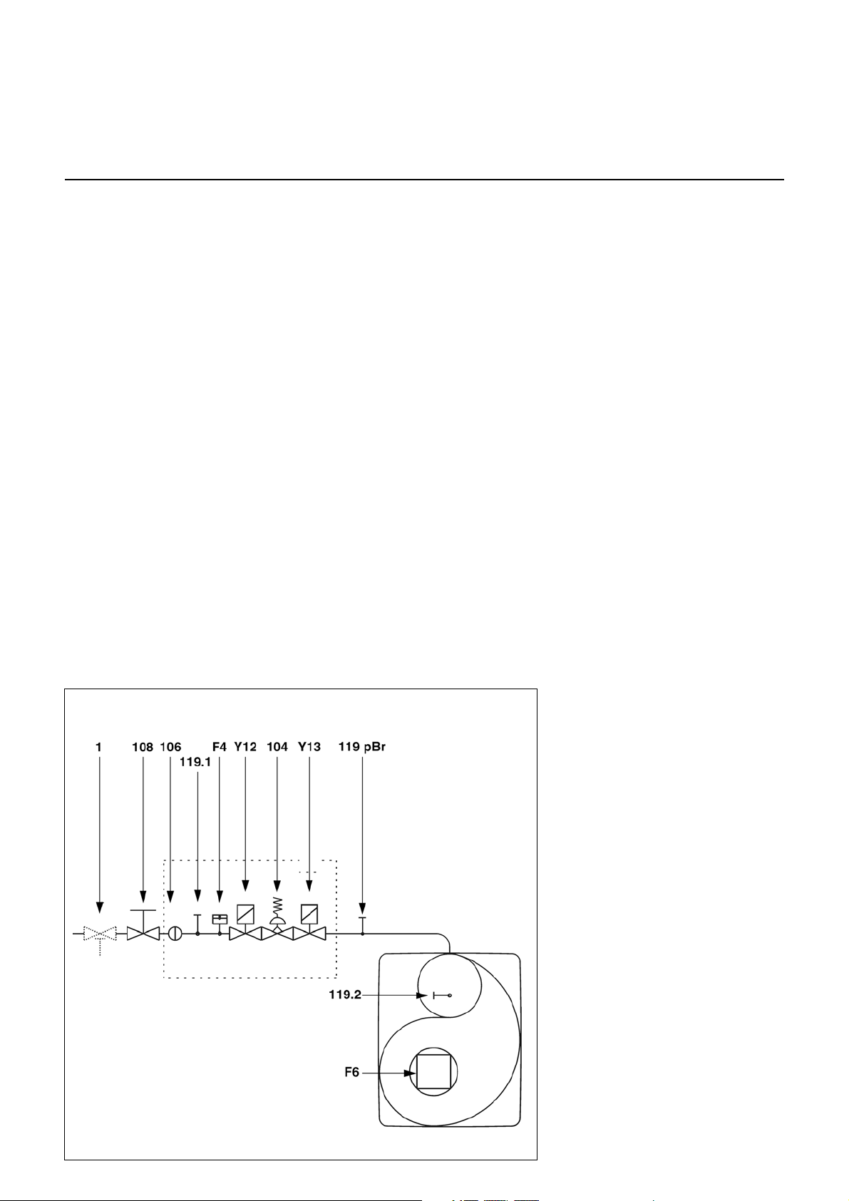
F4 Gasdrukbewaker
F6 Luchtdrukbewaker
Y12 Veiligheidsmagneetklep
Y13 Hoofdelektroklep
1 Thermische veiligheidsklep (door
de installateur te installeren)
104 Gasdrukregelaar
106 Zeef
108 Gasonderbrekingsklep (door de
installateur te installeren)
119pBrMeetpunt gasdruk bij de uitgang
van de klep
119.1Meetpunt gasdruk voor de kleppen
119.2Meetpunt luchtdruk
NB. CH
Volgens de instructies van de SSIGE, is
het verplicht een veiligheidsgasklep (nr.
1) in de leiding te installeren.
NB. DE
Volgens de standaard verordening voor
verbrandingsruimtes, moeten op
locaties met gasbranders bovendien
een thermisch in werking tredende
afsluiter worden gebruikt (nr. 1).
09/2014 - Art. Nr. 4200 1050 2800B4
Page 5

Functie
Compacte blok
nl
Werkingsfunctie met afdichtingscontrole
Veiligheidsfunctie
Functiebeschrijving
Bij het voor de eerste maal inschakelen,
na een stroomonderbreking en na een
uitschakelen in storingstoestand, na
gasgebrek of na 24 uur stilstand wordt
vóór de start van de brander een lektest
van de gasventielen doorgevoerd terwijl
de ventilatormotor draait. In aansluiting
aan de afdichtingscontrole begint de
voorventilatietijd van 24 sec.
Tijdens het voorspoelen wordt
- de ventilatordruk bewaakt
- de verbrandingskamer bewaakt op
vlamsignalen.
Na afloop van de voorspoeltijd
- wordt de ontsteking aangekoppeld
- wordt de hoofd- en
veiligheidsmagneetventiel geopend.
- Brander start
Bewaking
De vlam wordt bewaakt door een
ionisatiesonde. De sonde is geïsoleerd
op de gaskop gemonteerd en voert door
de stuwschijf naar de vlamzone. De
sensor mag niet in elektrisch contact
komen met geaarde onderdelen. Als er
tussen sonde en brandermassa
kortsluiting optreedt, schakelt de
brander op storing.
Bij branderwerking ontstaat in de
gasvlam een geïoniseerde zone,
waardoor een gelijkgerichte stroom van
de sonde naar de brandermond stroomt.
De ionisatiestroom moet ten minste 7 µA
bedragen.
Veiligheidsfuncties
- Als zich bij de start van de brander
(toelating gastoevoer) geen vlam
vormt, dan wordt na afloop van de
veiligheidstijd van max. 3 seconden
de brander uitgeschakeld en de
gasventiel wordt gesloten.
- Bij een verdwijning van de vlam
gedurende de werking wordt de
gastoevoer binnen een seconde
onderbroken. Er wordt dan een
nieuwe start uitgevoerd. Als de
brander start, wordt de werking
voortgezet. Zoniet volgt een
uitschakelen in storingstoestand.
- Bij gebrek aan lucht gedurende de
voorventilatie of de werking volgt
uitschakelen in storingstoestand.
- Bij gasgebrek gaat de brander niet in
werking of wordt uitgeschakeld. Er
volgt een wachttijd van 2 minuten.
Daarna wordt nog een startpoging
uitgevoerd. Als daarna geen gasdruk
voorhanden is, volgt nog een wachttijd
van 2 minuten. De wachttijd kan alleen
door een spanningsonderbreking van
de brander worden gereset.
Wachttijden: 3 x 2 min, daarna 1 uur.
Bij uitschakelen van de regeling
- De regelthermostaat onderbreekt de
aanvraag naar warmte
- De gasmagneetventielen gaan dicht
- De vlam dooft
- De ventilatormotor blijft in werking
gedurende een beperkte tijd
(standaard 14 sec) (in optie tot 90 sec)
- De lektest van de ventielen wordt
uitgevoerd
- De brandermotor wordt uitgeschakeld
- De brander is klaar voor werking
Optie: Snelle start met voortdurende
werking van de motor
Let op: Alleen voor goedgekeurde
warmteproducerende uitrusting
Functie:
- De ventilatormotor start, van de zodra
de brander met stroom wordt gevoed.
- De ventilatormotor werkt ook bij
werkingsgereedheid.
- Wanneer warmte wordt aangevraagd
wordt de brandermotor gedurende
korte tijd uitgeschakeld om de
ruststand van de luchtdrukschakelaar
te controleren.
- Vervolgens start de brander zonder
verdere voorventilatie binnen
ongeveer 4 sec.
Optie: Snelle start met lange
voorventilatie
Let op: Deze optie mag alleen worden
gebruikt bij warmteproducerende
uitrusting die hiertoe zijn
goedgekeurd door de fabrikant in
overleg met ELCO.
Functie:
Bij het voor de eerste maal inschakelen,
na een stroomonderbreking en na
gasgebrek of na 24 uur stilstand volgt
vóór het inschakelen van de brander
een voorventilatiefase die, naargelang
van de warmtegenerator, tot 600 sec
kan bedragen. Bij het volgende
uitschakelen van de regeling start de
brander bij een nieuwe aanvraag tot
warmte dan zonder voorventilatie
binnen 4 sec.
Bij deze optie is de automatische
afdichtingscontrole van de ventielen in
principe verplicht en mag niet worden
uitgeschakeld.
F4 Gasgebrekbeveiliging
F6 Luchtgebrekbeveiliging
Y13 Hoofdmagneetventiel
Y12 Veiligheidsmagneetventiel
1 Thermisch in werking tredende
veiligheidsafsluiter
(in het gebouw aan te brengen)
104 Gasdrukregelaar
106 Zeef
108 Gaskogelkraan (in het gebouw
aan te brengen)
119 Meetpunt gasuitgangsdruk
119.1Meetpunt luchtdruk
NB. CH
Volgens de instructies van de SSIGE, is
het verplicht een veiligheidsgasklep (nr.
1) in de leiding te installeren.
NB. DE
Volgens de standaard verordening voor
verbrandingsruimtes, moeten op
locaties met gasbranders bovendien
een thermisch in werking tredende
afsluiter worden gebruikt (nr. 1).
09/2014 - Art. Nr. 4200 1050 2800B 5
Page 6
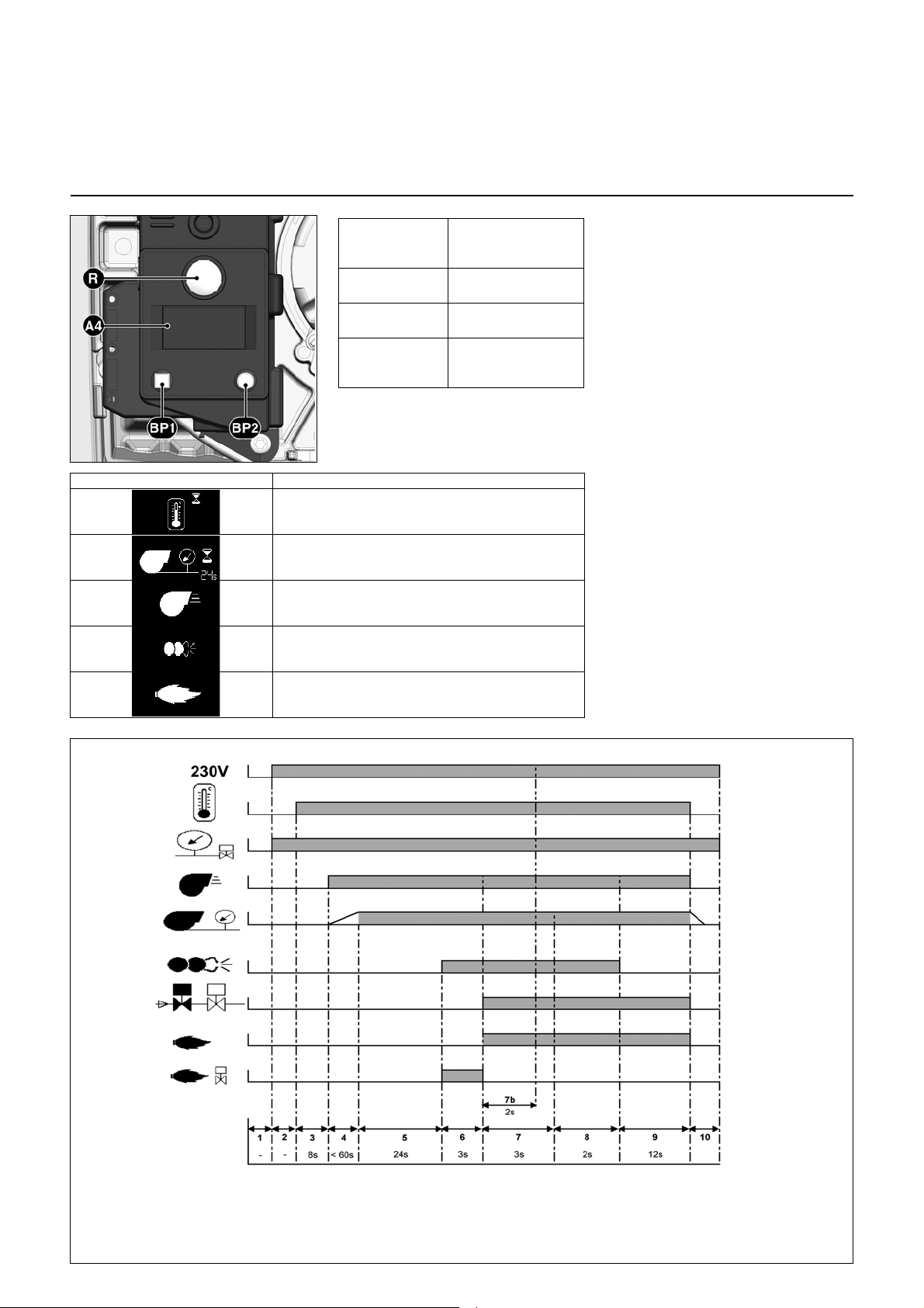
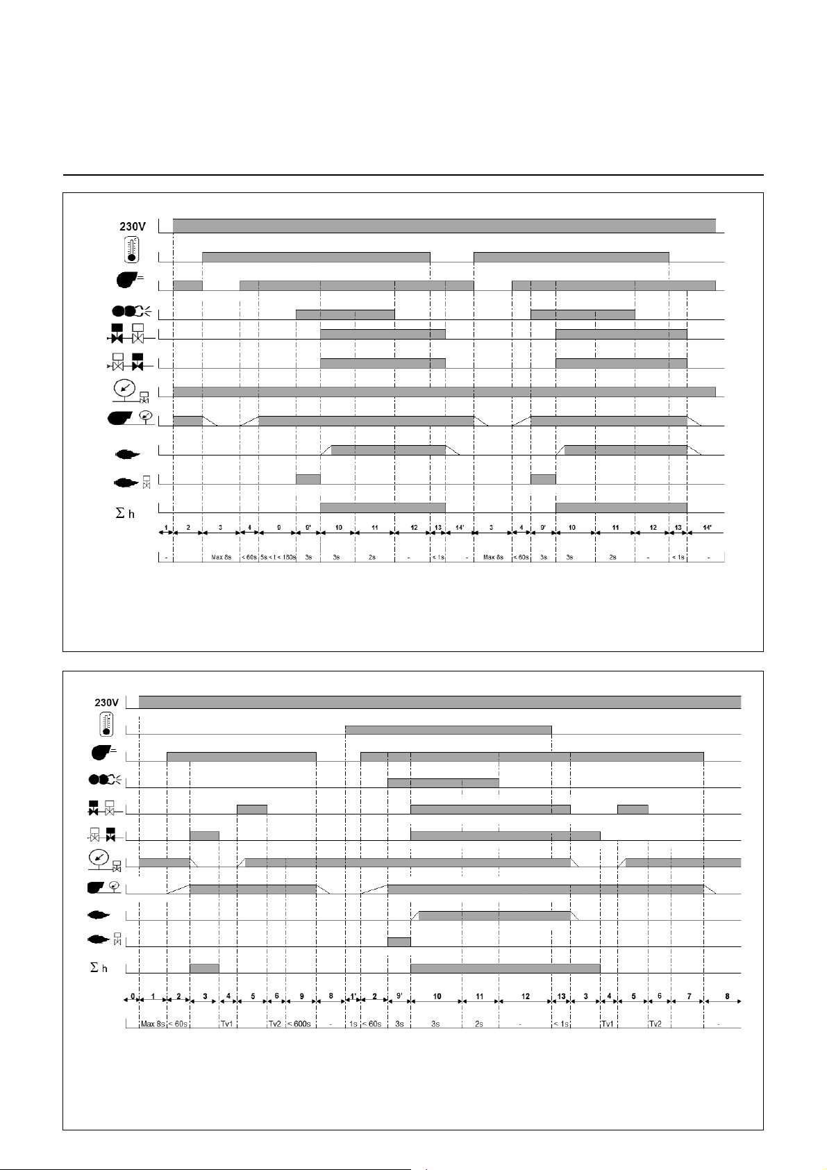
1: Geen spanning
2: Elektrische voeding aanwezig,
geen verzoek om verwarming
3: Verzoek om verwarming, controle
van de ruststand van de
luchtdrukbewaker
4: Motor gevoed, controle van de
luchtdruk
5: Voorventilatie
5': Voorontsteking, activering van de
vreemd lichtbewaking
6: Vlamvorming, veiligheidstijd
7: Tijd van de naontsteking
8: Werking
9: Stoppen van de brander
10: Stoppen van de regeling
Standaardfunctie
Functie
Branderautomaat TCG 1xx
Standaardfunctie zonder afdichtingscontrole
De knop R
indrukken tijdens
...
… 1 seconde ... Ontgrendelen van de
… 2 seconden... Vergrendelen van de
… 9 seconden... Wissen van de
A4 Scherm
BP1 Drukknop 1
Opvraging: Storingscode
BP2 Drukknop 2
Opvraging: Waarden
Symbool Naam
Wacht op warmteverzoek
Wacht op luchtpressostaat bij branderstart
Brandermotor ingeschakeld
Ontstekingstranformator ingeschakeld
… veroorzaakt ...
automaat
automaat
statistieken van de
automaat
De gasbranderautomaat TCG 1xx stuurt en
bewaakt de aangeblazen brander. Door het
microprocessorgestuurde
programmaverloop worden uiterst stabiele
tijden bereikt, die onafhankelijk zijn van
schommelingen in netspanning en
omgevingstemperatuur. De branderautomaat
is berekend op onderspanning, daardoor
komt de werking van de installatie ook bij
hevige spanningsdalingen niet in gevaar. Als
de netspanning onder de vereiste
minimumwaarde ligt, schakelt de automaat
uit zonder storingssignaal. Nadat weer een
normale spanning is bereikt, start de
automaat weer automatisch.
Vergrendeling en ontgrendeling
De automaat kan via de ontstoringsknop R
worden vergrendeld (in storingstoestand
gebracht) en worden ontgrendeld (uit
storingstoestand gehaald), op voorwaarde
dat netspanning voorhanden is aan de
automaat.
Voor het in- of uitbouwen van de
automaat moet het apparaat
spanningsvrij worden gemaakt. De
automaat mag niet geopend of
gerepareerd worden.
vlam aanwezig
09/2014 - Art. Nr. 4200 1050 2800B6
Page 7
Standaardfunctie
Functie
nl
Branderautomaat TCG 1xx
Standaardfunctie met afdichtingscontrole
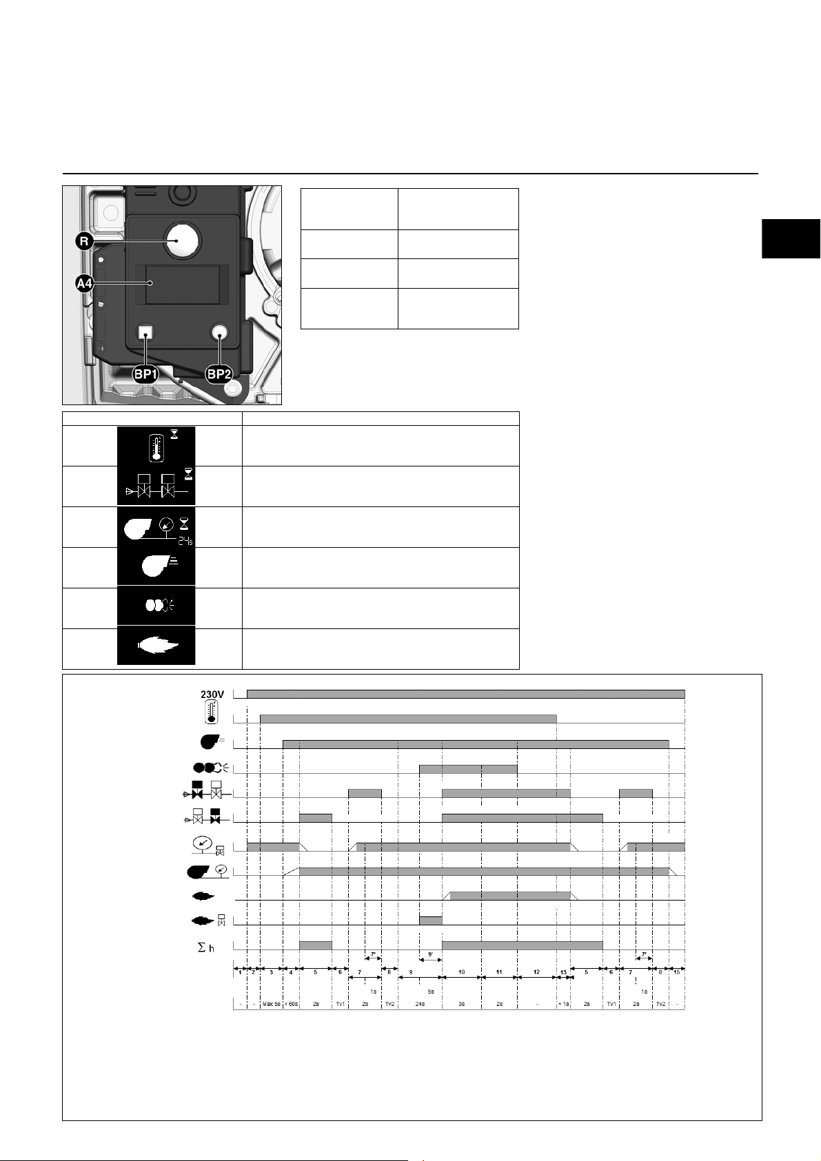
De knop R
indrukken tijdens
...
… 1 seconde ... Ontgrendelen van de
… 5 seconden... Vergrendeling van de
… 9 seconden... Wissen van de
A4 Scherm
BP1 Drukknop 1
Opvraging: Storingscode
BP2 Drukknop 2
Opvraging: Waarden
Symbool Naam
Wacht op warmteverzoek
Ventieldichtheitstest
(door gasdrukmeting in de tussenruimte van de
ventielen)
Wacht op luchtpressostaat bij branderstart
Brandermotor ingeschakeld
Ontstekingstranformator ingeschakeld
… veroorzaakt ...
automaat
automaat
statistieken van de
automaat
De gasbranderautomaat stuurt en
bewaakt de aangeblazen brander. Door
het computergestuurde
programmaverloop worden uiterst
stabiele tijden bereikt, die onafhankelijk
zijn van schommelingen in netspanning
en omgevingstemperatuur. De
branderautomaat is berekend op
onderspanning, daardoor komt de
werking van de installatie ook bij hevige
spanningsdalingen niet in gevaar. Als de
netspanning onder de vereiste
minimumwaarde ligt, schakelt de
automaat uit zonder storingssignaal.
Nadat weer een normale spanning is
bereikt, start de automaat weer
automatisch.
Vergrendeling en ontgrendeling
De automaat kan via de ontstoringsknop
R worden vergrendeld (in
storingstoestand gebracht) en worden
ontgrendeld (uit storingstoestand
gehaald), op voorwaarde dat
netspanning voorhanden is aan de
automaat.
Als de knop in normale werking of tijdens
het opstarten wordt ingedrukt, dan gaat
het apparaat over in de storingstoestand.
Als de knop bij storing wordt ingedrukt,
wordt de automaat ontgrendeld.
Voor het in- of uitbouwen van de
automaat moet het apparaat
spanningsvrij worden gemaakt. De
automaat mag niet geopend of
gerepareerd worden.
Fasen functieverloop:
1: geen spanning
2: Spanningsvoeding voorhanden, geen
3: Aanvraag tot warmte, controle
4: Motor ingeschakeld, controle luchtdruk
5: Eerste fase dichtheidscontrole (ruimte
aanvraag tot warmte
luchtdrukschakelaar ruststand
vlam aanwezig
tussen de ventielen zonder druk)
6: Tijdsduur controle 1
7: Tweede fase van de ventielcontrole
(ruimte tussen de ventielen gevuld)
8: Tijdsduur controle 2
9: Voorventilatie
9': Voorontsteking, activering
parasietlichtbewaking
09/2014 - Art. Nr. 4200 1050 2800B 7
10: Vlamvorming, veiligheidstijd
11: Naontstekingstijd
12: Bedrijf
13: Branderstilstand
14: Naventilatie
14': Voortdurende werking van de motor
15: Werkingsgereedheid
Page 8
Functie
Fasen functieverloop:
1: geen spanning
2: Spanningsvoeding voorhande n,
geen aanvraag tot warmte
3: Aanvraag tot warmte, controle
luchtdrukschakelaar ruststand
4: Motor ingeschakeld, controle
luchtdruk
9: Voorventilatie
9': Voorontsteking, activering van
de parasietlichtbewaking
10: Vlamvorming, veiligheidstijd
11: Naontstekingstijd
12: Werking
13: Branderstilstand
14: Naventilatie
14': Voortdurende werking van de
motor
Snelle start met voortdurende werking van de motor
Fasen functieverloop:
0: geen spanning
1: Spanningsvoeding voorhanden, geen
aanvraag tot warmte, controle
luchtdrukschakelaar in ruststand
1’: Aanvraag tot warmte
2: Motor ingeschakeld, controle luchtdruk
3: Eerste fase dichtheidscontrole
(ruimte tussen de ventielen zonder
druk)
4: Tijdsduur controle 1
5: Tweede fase van de ventielcontrole
(ruimte tussen de ventielen gevuld)
6: Tijdsduur controle 2
7: Einde naventilatie
8: Werkingsgereedheid
9: Voorventilatie
9’: Voorventilatie/parasietlichtbewaking/
voorontsteking
10: Vlamvorming, veiligheidstijd
11: Naontstekingstijd
12: Werking
13: Branderstilstand
Snelle start met lange voorventilatie
Branderautomaat TCG 1xx
Snelle start met voortdurende werking van de motor
Snelle start met lange voorventilatie
09/2014 - Art. Nr. 4200 1050 2800B8
Page 9
Functie
Stekker
nr.
Klem
Klem
Stekker
nr.
Vlamcontrole
Afstandsontgren
deling
Ontstekin
Brandermotor
LuchtpressostaatGaspressostaat Stroomvoeding L1
Display Storing
Magneetventiel
Aarde
Aarde
nl
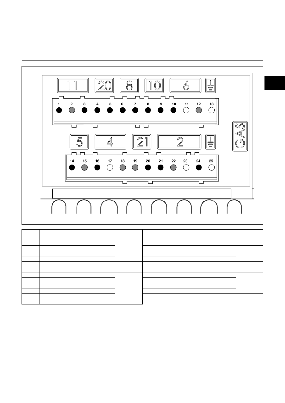
Aansluitschema
Aansluitsokkel
Klem Benaming Stekker nr. Klem Benaming Stekker nr.
1 Signaal vlamdoofveiligheid
2 Neutraal 15 Neutraal
3 Fase 16 Fase brandermotor
5 Fase 18 Neutraal
6Fase
7 Signaal gaspressostaat 20 Fase display storing
8 Signaal luchtpressostaat
9 Fase 22 Neutraal
10 Fase
11 Aarde 24 Fase hoofdgasventiel
12 Neutraal 25 Aarde
13 Aarde
11
20
8
10
6
14 Fase onstekingstransformator
17 Aarde
19 Neutraal
21 Fase veiligheidsventiel
23 Aarde
5
44 Signaal afstandsontgrendeling
21
1
09/2014 - Art. Nr. 4200 1050 2800B 9
Page 10
Functie
P2.G
P2.G/TC
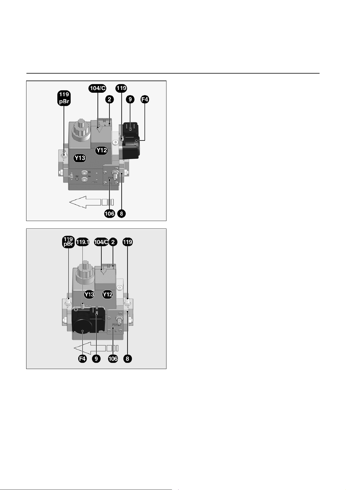
Gasblok MB-DLE
Het compacte gasblok MB-DLE ...
ingebouwde gasdrukregelaar is
bestemd voor gasbranders met
geforceerde luchttoevoer met een
snelheid.
Het compacte gasblok draagt de
goedkeuring CE 0085 AP3156.
Technische gegevens
Ingangsdruk 13-360 mbar
Omgevingstemperatuur -15 tot +60°C
Spanning 230 V / 50 Hz
Opgenomen vermogen 46 W
Beschermingsindex IP54
Gasaansluiting Rp 3/4"
met
Werking
Door het onder spanning zetten van de
magneetspoelen openen de kleppen
Y12 en Y13. De klepzetels zijn tegen vuil
beschermd door een stroomopwaarts
geplaatst zeefje. De ingebouwde
drukregelaar regelt de gewenste
uitgangsdruk.
De benodigde instelwaarden voor:
- de gasdrukbewaker
- de gasdrukregelaar
- de startgasdruk
kunnen met schroeven worden
ingesteld. De ingangs- en
uitgangsdrukken kunnen worden
gemeten op de drukaansluitingen.
F4 Drukschakelaar (instelschroef
onder de kap)
Y12 Veiligheidsklep
Y13 Hoofdklep
2 Elektrische aansluiting van de
kleppen
8 Inlaatflens
9 Elektrische aansluiting van de
drukschakelaar
104/C Instelschroef van de
drukregelaar
106 Gasfilter
119 Meetpunt gasingangsdruk
119pBr Meetpunt gasuitgangsdruk
09/2014 - Art. Nr. 4200 1050 2800B10
Page 11

Montage
nl
Montage van de brander
Montage van de brander
De branderflens 3 is uitgerust met
langgaten en kan voor een gat- van 150
- 184mm worden gebruikt. Deze maten
voldoen aan EN 226.
Door verschuiven van buizensteun 2 op
de branderbuis kan de insteekdiepte
van het mengtoestel aangepast worden
aan de afmetingen van de
verbrandingsruimte. De insteekdiepte bij
het in- en uitbouwen ongewijzigd.
Door de buizensteun 2 wordt de brander
op de aansluitflens en dus aan de ketel
bevestigd. De verbrandingsruimte wordt
hierdoor dicht afgesloten.
Inbouwdiepte van de branderbuis en
inmetselen
Bij verwarmers zonder gekoelde
voorwand is, in zoverre de ketelfabrikant
geen andere opgave doet, een
gemetselde bekleding of een isolatie 5,
zoals hiernaast afgebeeld, noodzakelijk.
Het inmetselen mag de voorkant van de
vlambuis niet overlappen en moet met
niet meer dan 60° conisch toelopen. De
luchtspleet 6 moet worden opgevuld met
een elastisch, onbrandbaar
isolatiemateriaal.
Inbouwen:
• Aansluitflens 3 met bouten 4 aan de
ketel bevestigen
• Buizensteun 2 op branderbuis
monteren en met bout 1 bevestigen.
Bout 1 met een aantrekmoment van
max. 6 Nm vastdraaien.
• Brander enigszins draaien, in de flens
invoeren en met bout 5 bevestigen.
Uitbouwen:
• Bout 5 losdraaien
• Brander uit de bajonetsluiting draaien
en uit de flens trekken.
Voor een montage van de brander
in omgekeerde positie, moet ook
de weergave worden omgekeerd.
Hiertoe houdt u, als de brander
onder spanning staat, de toetsen
BP1 en BP2 tegelijk ingedrukt tot
u de verandering constateert.
Dit is alleen mogelijk als de
brander is gestopt!
Roofgasafvoersysteem
Om eventuele geluidshinder te
voorkomen, dient bij de verbinding van
de ketel met het rookgaskanaal het
gebruik van aansluitstukken met een
rechte hoek te worden vermeden.
Bij ketels met omkeerverbranding moet
rekening gehouden worden met de
minimale insteekdiepte A van de
vlambuis conform opgave van de
ketelfabrikant.
Peilglaskoeling
Het branderhuis kan met een R1/8"aansluiting voor de opname van een
leiding voor de peilglaskoeling van de
ketel worden voorzien.
• Hiervoor gietrand 6 doorboren en 1/8"-
schroefdraad snijden.
Voor aansluitnippel en verbindingsslang
toebehoor Art. Nr. 12 056 459
gebruiken.
09/2014 - Art. Nr. 4200 1050 2800B 11
Page 12

Montage
Montage van de gasarmatuur
Controle van de branderkop voor aardgas / propaan
Montage van de gasarmatuur
• Controleren of ringafdichting J1
aanwezig is en correct op de flens ligt.
• Gasarmatuur rechts of links met
spoelen in bovenste verticale stand
bevestigen.
• Let op de circulatierichting.
Controle van het mengtoestel
• De drie dekselbouten W losmaken.
• Deksel verwijderen.
• Contramoer E van de gasbuissteun
losmaken
• Borgbout losmaken
• Mengtoestel eruit trekken.
Instelling op vloeibaar-gaswerking
• Stuwschijf 4 demonteren.
• Tussenstuk GP (bij behuizing
geleverd) monteren.
• Stuwschijf weer monteren.
Controle van het mengtoestel
• Instelling van de ionisatiesonde en de
ontstekingssonde volgens
afbeeldingen controleren.
09/2014 - Art. Nr. 4200 1050 2800B12
Page 13
Inbedrijfstelling
nl
Elektrische aansluiting
Controles vóór de inbedrijfstelling
Ionisatiestroommeting
Algemene voorschriften voor
gasverzorging
• De aansluiting van de gasarmatuur op
het gasnet mag alleen door een
erkend vakman worden uitgevoerd.
• De diameter van de gasleiding moet
zo vormgegeven zijn dat de
voorgeschreven gasstroomdruk niet
onderschreden wordt.
• Vóór de gasarmatuur moet een
handbediende gaskraan (niet
meegeleverd) worden gemonteerd.
• In Duitsland moet volgens voorbeeldverbrandingsverordening bovendien
een thermisch in werking tredende
afsluiter (door de klant te installeren)
worden gebruikt.
Bij de inbedrijfstelling van de brander
wordt de installatie gelijktijdig onder
verantwoording van de installateur of
zijn zaakwaarnemer afgenomen. Alleen
hij kan waarborgen dat de installatie
overeenstemt met de normen en
voorschriften. De installateur moet
erkend zijn en de installatie op lekkages
gecontroleerd en ontlucht hebben.
Het installeren van de elektra en de
aansluitwerkzaamheden mogen
uitsluitend worden uitgevoerd door
een erkend elektricien. Hierbij dienen
de geldende voorschriften en
richtlijnen in acht te worden genomen.
Houd u stipt aan de geldende
voorschriften en richtlijnen
en aan het bij de brander
geleverd elektrische
schema!
Elektrische aansluiting
• Controleer of de netspanning eenfasig
230 V, 50 Hz is met neutraal en aarde.
Zekering op de ketel: 10 A
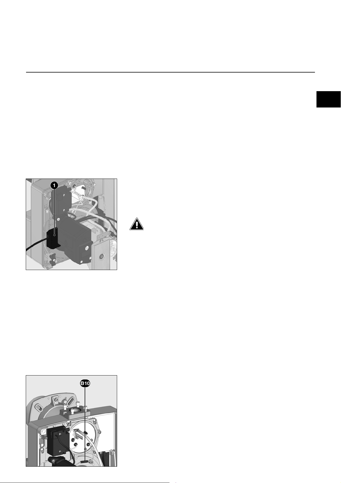
Elektrische stekkerverbindingen
De brander moet van het net
gescheiden kunnen worden met een
omnipolair uitschakeltoestel. De brander
en de verwarmer (ketel) worden via een
zevenpolige steker Wieland 1 (niet
meegeleverd) met elkaar verbonden.
De diameter van de op deze steker
aangesloten kabel moet absoluut tussen
8,3 en 11 mm liggen.
Aansluiting gasarmatuur
Aansluiting van de gasarmatuur op de
zich op de brander bevindende stekkers
(zwart op zwart, grijs op grijs) maken.
Controles vóór de inbedrijfstelling
Vóór de inbedrijfstelling moeten de
volgende punten worden gecontroleerd.
• Montage van de brander volgens de
bijgeleverde handleiding.
• Voorinstelling van de brander conform
opgave insteltabel.
• Instelling van het mengtoestel
• De warmtebron moet klaar voor
inbedrijfstelling gemonteerd zijn, de
voorschriften voor het gebruik van de
warmtebron moeten worden
opgevolgd.
• Alle elektrische aansluitingen moeten
correct uitgevoerd zijn.
• De warmtebron en het
verwarmingssysteem zijn met water
gevuld, de circulatiepompen zijn in
werking.
• De temperatuurregelaar,
drukregelaar, droogloopbeveiliging en
andere eventueel aanwezige
beveiligende
begrenzingsvoorzieningen moeten
correct aangesloten zijn en
functioneren.
• De rookgaswegen moeten vrij zijn en
de secundaire-luchtvoorziening,
indien aanwezig, moet in werking zijn.
• Voldoende toevoer van verse lucht
moet gewaarborgd zijn.
• Het verzoek om warmte moet
aanwezig zijn.
• Er moet voldoende gasdruk
Ionisatiestroommeting
Voor de meting van de ionisatiestroom,
de steker B10 losmaken en een
multimeter met een meetbereik van 0100 µA aansluiten.
De ionisatiestroom moet groter zijn dan
7 µA. Het is ook mogelijk om de
ionisatiestroomsterkte te raadplegen op
het display.
beschikbaar zijn.
• De brandstofleidingen moeten
vakkundig gemonteerd en ontlucht
zijn en op lekkages gecontroleerd zijn.
• Een meetplaats volgens de normen
voor de meting van rookgas moet
aanwezig zijn, het rookgastraject tot
en met de meetplaats moet dicht zijn,
zodat de meetresultaten niet worden
vervalst door valse lucht.
09/2014 - Art. Nr. 4200 1050 2800B 13
Page 14
Inbedrijfstelling
G20 G25 G31
30 2 0,3 0
70 20 0,7 30 9,6 12,8 5,4
75 20 0,7 12 3,8 4,3 3,1
100 20 0,9 60 6,1 6,9 5,1
115 35 1 90 7,5 8,6 6,3
185 35 1,3 80
77,55,5
P2.160
G (TC)
P r e ssi o n
fo y e r
pF
(m b a r)
Positie
lu ch tk le p
(°)
Maat Y
(m m )
In ste llin g g a skle p
gasdruk bij de kop pBr
(m b a r)
MB-...407
Brandervermogen
(k W )
P2.70
G (TC)
P2.120
G (TC)
Instelgegevens
50 10 0,5 10 5,3 7 3,1
80 10 0,7 20 1,8 2 1,5
110 25 0,9 60 4,8 5,5 4,5
140 20 0,9 70 - - -
De instelgegevens hierboven zijn ter
indicatie om de inbedrijfstelling te
vergemakkelijken. De
fabrieksinstellingen zijn vet gedrukt op
een grijze ondergrond. De definitieve
instellingen zijn absoluut noodzakelijk
om de beste werking van de brander te
garanderen.
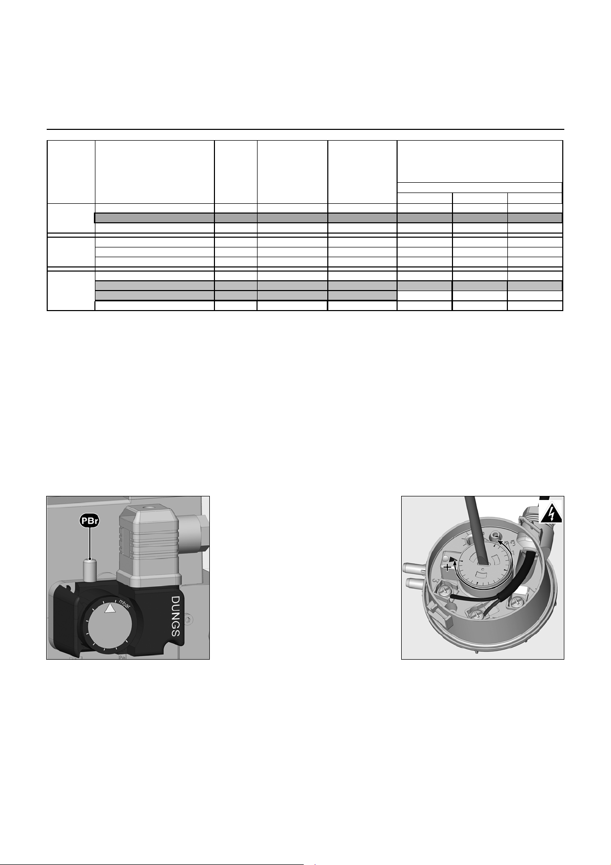
Instelling van de gasdrukbewaker
• Doorzichtig deksel verwijderen.
• Stel de waarde van de gasdruk bij de
kop in de 2
e
trap tijdelijk in 5mbar.
Instelling van de luchtdrukbewaker
• Doorzichtig deksel verwijderen.
• Tijdelijk instellen op 1 mbar.
2,4 3,1 1,5
09/2014 - Art. Nr. 4200 1050 2800B14
Page 15

Inbedrijfstelling
nl
Luchtregeling
Luchtregeling
De regeling van de verbrandingslucht
gebeurt op twee plaatsen:
• aan drukzijde via de spleet tussen de
vlammenhaker en branderbuis.
• aan aanzuigzijde via de handmatig
met de regelknop instelbare luchtklep.
De luchtregeling in de branderkop
beïnvloedt behalve de luchthoeveelheid
ook de mengzone en de luchtdruk in de
branderbuis.
- Verdraaien van de schroef A
naar links: minder lucht
naar rechts: meer lucht
• Stel de maat Y in conform de
insteltabel.
Luchtregeling via luchtklep
De luchtregeling aan aanzuigzijde
gebeurt via een luchtklep. Deze wordt
ingesteld door de knop 103B.
09/2014 - Art. Nr. 4200 1050 2800B 15
Page 16

Borg-schroef
Verzegelde
schroef
Instelbout van de
gasdrukregelaar
Inbedrijfstelling
Instelling compacte gaseenheid MB-DLE
Instelling drukregelaar
Voor het instellen van de uitgangsdruk
zijn 60 slagen van de instelschroef
mogelijk. Drie slagen rechtsom
verhogen de druk met 1 mbar, drie
slagen linksom verlagen de druk met
dezelfde waarde.
Bij de inwerkingstelling:
• Ten minste 20 slagen rechtsom (+)
• Gasdruk na de regelaar pBr moet zijn:
12-15 mbar.
Instelling nominale belasting
• De borgschroef losmaken tot de
draaiknop 6 kan worden versteld. De
verzegelde bout aan de
tegenoverliggende zijde niet losdraaien.
• De hoofddoorstroomhoeveelheid door
draaien aan knop 6 naar rechts
verminderen resp. door draaien naar
links verhogen. Het totale traject voor
verandering van minimaal tot maximaal
debiet is ongeveer 4,5 slagen.
• Wanneer de instelling met succes
voltooid is, de borgschroef weer
vastschroeven.
• Gasdruk op het meetpunt
(fabrieksinstelling op pagina 14).
119pBr
meten
Instelling startlasthoeveelheid snelslaginstelling
• Beschermkap 5 eraf draaien en over
180° gedraaid als regelgereedschap
gebruiken.
• Instelstift tot aan de aanslag naar min.stand draaien, dan in plus-stand tot
aan de middelste stand (ca. 3 halve
slagen) terugdraaien. De
startgashoeveelheid is nu ongeveer
half open.
• Om zacht opstartgedrag te bereiken
moet het gasdebiet bij het starten
worden aangepast aan de
drukverhoudingen van de
warmteproducerende uitrusting.
Verbrandingswaarden optimaliseren
Zo nodig verbrandingswaarden via
instelling van de stuwschijfstand (maat Y)
optimaliseren. Hierdoor kan het
startgedrag, de pulsatie en de
verbrandingswarmte worden beïnvloed. Bij
reductie van de schaalwaarde Y stijgt de
CO2-waarde, het startgedrag wordt echter
harder. Indien nodig
luchthoeveelheidwijziging door aanpassing
van luchtklepstand compenseren.
Let op: Minimaal noodzakelijke
rookgastemperatuur in acht nemen
volgens opgave van de ketelfabrikant
en overeenkomstig eisen
rookgaswegen ter voorkoming van
condensatie.
Controle van de regelbaarheid
• De brander op de nominale belasting
laten werken.
• Gasdruk op punt 119 en punt 119pBr
meten.
• De kogelkraan voor de compacte
eenheid langzaam sluiten, tot de
ingangsdruk van het gas bij 119 met
20daPa vermindert.
De gasuitgangsdruk bij 119pBr
mag daarbij ten hoogste met 10%
dalen.
Overigens moet de instelling
worden gecontroleerd en
gecorrigeerd.
De installatie mag niet in bedrijf
worden genomen als de
regelbaarheid onvoldoende is.
• Kogelkraan weer openen.
09/2014 - Art. Nr. 4200 1050 2800B16
Page 17

Inbedrijfstelling
nl
Instelling gaspressostaat
Instelling luchtpressostaat
Werkingscontrole
Instelling gaspressostaat
• Voor instelling van de uitschakeldruk: Het
deksel van de gaspressostaat verwijderen.
• Meetinrichting voor gasdruk pBr
aansluiten.
• Brander starten.
• Gasdruk voor blok verminderen door het
vernauwen van de kogelkraan, tot ofwel:
- gasdruk pBr na het blok vermindert tot
70%
- de stabiliteit van de vlam zichtbaar
afneemt
- de CO-waarde stijgt
- of het vlamsignaal verslechtert merkbaar
• De instelschijf rechtsom draaien, tot de
gaspressostaat de brander uitschakelt.
• Door verder rechtsom draaien de
gaspressostaat 10% hoger dan de
gemeten uitschakelwaarde instellen.
Instelling luchtpressostaat
Voorinstelling van de fabriek: 1,0mbar
Het schakelpunt moet bij het inregelen
worden getest en bijgeregeld.
• Het drukmeetapparaat installeren,
daartoe T-stuk in de drukleiding
bouwen.
• Brander in werking stellen.
• Schakelpunt ongeveer 15% onder de
nu aanwezige uitschakeldruk
instellen.
De instelwaarde van de gasdrukschakelaar
moet hoger liggen dan de ventilatordruk,
maar lager dan de gasdruk na het gasventiel.
Als de zo vastgestelde
onderbrekingswaarde hoger is dan
150 mbar, stel dan de drukbewaker in
op 150 mbar.
Controle van het uitschakelpunt:
• Manuele afsluiter openen
• Brander starten
• Manuele afsluiter sluiten
Het gasgebrekprogramma moet starten,
zonder dat de branderautomaat een
uitschakelen in storingstoestand veroorzaakt.
Werkingscontrole
Een controle van de vlambewaking moet
zowel bij het eerste gebruik als ook na
een revisie of een lange stilstand van de
installatie worden uitgevoerd.
- Opstarttest met gesloten gasventiel:
Op het einde van de veiligheidstijd
moet de branderautomaat overgaan
op gasgebrek of storing.
- Opstarten met gesloten
luchtpressostaat:
De brander gaat na een controletijd
van 8 sec. over op storing.
- Opstartpoging met geopende
luchtpressostaat:
Na een wachttijd van 60 sec. gaat de
branderautomaat over op storing.
- Opstartpoging met korte, geopende
luchtpressostaaat gedurende de
voorventilatie:
De branderautomaat start het
voorventilatieprogramma opnieuw,
wanneer de luchtdruk binnen 60 sec.
opnieuw voorhanden is, anders volgt
een uitschakelen in storingstoestand.
09/2014 - Art. Nr. 4200 1050 2800B 17
Page 18

Service
Onderhoud
Onderhoudswerkzaamheden aan de ketel
en brander mogen uitsluitend door een
erkende verwarmingsmonteur worden
uitgevoerd. Om een jaarlijkse uitvoering
van de onderhoudswerkzaamheden te
waarborgen, wordt het afsluiten van een
onderhoudscontract aanbevolen.
Afhankelijk van het type van de
installatie, kunnen kortere
onderhoudsintervallen nodig zijn.
• Vóór onderhouds- en
schoonmaakwerkzaamheden, de
elektrische voeding uitschakelen.
• Originele vervangingsonderdelen
gebruiken.
In het kader van het jaarlijks onderhoud
aan de brander aanbevolen
werkzaamheden:
- Test van de brander, meting bij aankomst in
de verwarmingsruimte
- Reinigen van het mengtoestel en zo nodig
defecte onderdelen vervangen
- Ventilatorwiel en ventilator reinigen
- Reinigen van het gasfilter; indien nodig
vervangen
- Visuele controle van de elektrische
componenten van de brander; aanwezige
storingen verhelpen
- Branderstart controleren
- Afdichtingscontrole
- Functiecontrole van de
veiligheidsvoorzieningen van de brander
(luchtdruk-/gasdrukbewaker)
- Functiecontrole van de vlambewaker en
van de branderautomaat
- Inschakelen van de brander
- Gasdoorstroming controleren
- Correctie van de instelwaarden indien
nodig
- Meetprotocol opstellen
Algemene controles
- Controle van de werking van de
noodstopschakelaar
- Visuele controle van de gasvoerende
leidingen in de verwarmingsruimte
Controle van het mengtoestel
• Branderkap verwijderen.
• Ontstekingskabel aan trafozijde
lostrekken.
• De drie dekselbouten W losdraaien.
• Deksel verwijderen.
• Contramoer E van de gasbuissteun
losdraaien
• Borgbout losdraaien.
• Mengtoestel eruit trekken.
• Toestand van de stuwschijf
controleren.
• Stand van de ontstekingselektrode en
de ionisatiesonde controleren.
• Bij het weer inbouwen op juiste
kabelgeleiding en correcte passing
van de O-ring J2 letten.
• Op lekkages controleren.
Reiniging ventilatiewiel
• Toestelplaat verwijderen en in servicepositie inhangen (zie afbeelding).
• Ventilatiewiel verwijderen en reinigen,
zo nodig vervangen en in omgekeerde
volgorde weer in elkaar zetten.
Montage van de turbine
Bij het vervangen van de motor of van
de turbine raadpleegt u het
plaatsingsschema hiernaast. De
binnenste flens A van de turbine moet
op een lijn zijn met de plaat B. Steek een
liniaal tussen de schoepen van de
turbine en breng A en B op gelijke
hoogte. Zet de puntschroef vast op de
turbine.
09/2014 - Art. Nr. 4200 1050 2800B18
Page 19

Service
nl
Onderhoud
Vervangen van de vlambuis
Voor dit proces is het noodzakelijk om
de brander uit te bouwen.
• Klembout van aansluitflens
losdraaien.
• Brander uit de bajonetsluiting draaien,
iets optillen en uit de aansluitflens
trekken.
• Brander op de vloer leggen.
• De 4 bouten S van de vlambuis
losdraaien.
• Vlambuis naar voren eruit trekken.
• Vlambuis inbouwen en bevestigen.
Vlambuis kan heet zijn
Filter vervangen
• Het filterelement van het multiblok
moet ten minste één keer per jaar
gecontroleerd en bij verontreiniging
vervangen worden.
• Bouten van het filterdeksel op het
multiblok losdraaien.
• Het filterelement verwijderen en de
houder reinigen.
• Geen onder druk staand
schoonmaakmiddel gebruiken.
• Het filterelement vervangen door een
nieuw element.
• Deksel weer vastschroeven.
• Handmatige afsluiter weer openen.
• Op lekkages controleren.
• Verbrandingswaarden controleren.
Reinigen van de kap
• Geen chloorhoudende of schurende
middelen gebruiken.
• Kap met water en een
schoonmaakmiddel schoonmaken.
• Kap weer monteren.
Belangrijk
Na iedere ingreep: de
verbrandingswaarden in de normale
bedrijfsomstandigheden controleren
(deuren gesloten, kap gemonteerd,
enz.). De gemeten waarden moeten
worden genoteerd op de formulieren
van de verbrandingskamer.
Controle van de rookgastemperatuur
•
Regelmatig de rookgastemperatuur
controleren.
• Ketel reinigen, als de
rookgastemperatuur de waarde van
de inbedrijfstelling met meer dan
30 °C overschrijdt.
• Om de controle te vereenvoudigen
een rookgasthermometer gebruiken.
Reiniging van de luchtaanzuigkast
• Bevestigingsbouten V van
luchtaanzuigkast eruit draaien.
• Luchtaanzuigkast verwijderen en
reinigen en in omgekeerde volgorde
weer in elkaar zetten.
• Op de correcte stand van luchtklep
letten.
09/2014 - Art. Nr. 4200 1050 2800B 19
Page 20

Service
Storingen verhelpen
Oorzaken en verhelpen van
storingen
Als de storing blijft bestaan, de volgende
tabel gebruiken.
Gebruik alleen originele
onderdelen van de fabrikant.
Bij storingen moeten de principiële
voorwaarden voor een goede werking
worden gecontroleerd:
1. Is er stroom aanwezig?
2. Is er gasdruk aanwezig?
3. Is de gasafsluiter geopend?
4. Is alle regel- en
veiligheidsapparatuur, zoals
ketelthermostaat, beveiliging
watertekort, eindschakelaars enz.
De componenten die met veiligheid
verband houden, mogen niet worden
gerepareerd, en moeten door onderdelen
met hetzelfde bestelnummer worden
vervangen.
Aanwijzing:
Na iedere ingreep:
• Onder de werkelijke
werkingsvoorwaarden (deuren
gesloten, kap gemonteerd enz.) de
verbranding controleren en alle
leidingen op dichtheid controleren.
• De resultaten in de betreffende
documenten noteren.
correct ingesteld?
Symbool Storing Oorzaak Verhelpen
geen aanvraag naar warmte Thermostaat defect of ontregeld. Thermostaten instellen of vervangen.
Brander start niet na
thermostaatuitschakeling.
Er is geen storingsmelding op de
branderautomaat.
De brander start bij het
inschakelen heel kort, schakelt uit
en de rode lichtdiode gaat
branden.
De brander start niet. Luchtpressostaat: niet in rusttoestand
De brander start niet.
Gasdruk normaal
De branderventilator start. De
brander start niet.
Geen of te lage netspanning.
Storing van de automaat
De automaat werd opzettelijk uitgeschakeld. Automaat ontgrendelen.
Foutieve instelling
Contact gelast
onvoldoende gasdruk
Gaspressostaat ontregeld of defect
Luchtpressostaat: het contact sluit niet. Druksensor controleren (vreemde
Oorzaak van te lage spanning of van
stroomonderbreking opsporen.
De automaat vervangen.
Pressostaat opnieuw instellen.
Pressostaat vervangen.
Gasleidingen controleren.
Filter reinigen.
Gaspressostaat controleren of
compacte gaseenheid vervangen.
voorwerpen) en bekabeling controleren.
De branderventilator start. De
brander start niet.
Brander start, ontsteking schakelt
in, dan afbreking
De brander stopt terwijl hij werkt. Luchtpressostaat: Contact opent bij de start of
Strooilicht bij de voorventilatie of
voorontsteking.
Geen vlam na afloop van de beveiligingstijd.
Het gasdebiet is foutief ingesteld.
Storing in het vlambewakingscircuit
Geen ontstekingsboog.
Elektrode(n) kortgesloten.
Ontstekingskabel beschadigd of defect.
Ontstekingstransformator defect.
Branderautomaat.
De magneetventielen openen niet.
Klemmen van de ventielen.
tijdens werking.
De vlam verdwijnt gedurende de werking.
Ventiel controleren. Vlambewaking
controleren.
Gasdebiet regelen.
Toestand en stand van de
ionisatiesonde t.o.v. de massa
controleren.
Toestand en aansluitingen van het
ionisatiecircuit controleren (kabel en
meetbrug).
Elektrode(n) instellen, reinigen of
vervangen.
De kabel(s) aansluiten of vervangen.
Trafo vervangen.
De automaat vervangen.
Kabels tussen automaat en externe
componenten controleren.
Compacte gaseenheid vervangen.
Ventielen vervangen.
Pressostaat instellen of vervangen.
Circuit van de ionisatiesonde
controleren.
Branderautomaat controleren of
vervangen.
09/2014 - Art. Nr. 4200 1050 2800B20
Page 21

Service
nl
Aanduiding onderhoudsinterval
Gedurende de werking kunnen na enige
tijd de volgende inlichtingen verschijnen:
A4 Scherm
BP1 Drukknop 1
Opvraging: Storingscode
BP2 Drukknop 2
Opvraging: Waarden
Om het telefoonnummer te wijzigen:
• Door indrukken van BP1 het
storingsmenu oproepen en de uitlezing
door verder bedienen van BP1 laten
doorlopen tot het gewenste pictogram
verschijnt.
• Op BP2 drukken om de wijziging in te
geven: het eerste cijfer knippert.
• De waarde (van 0 tot 9) door herhaald
drukken van BP1 kiezen.
• Op BP2 drukken om te bevestigen.
• De procedure herhalen tot het laatste
cijfer.
Dat betekent dat het
tijd is voor
door een vakman.
Als de installateur zijn
telefoonnummer
heeft opgetekend, dan
verschijnt dat,
alsook het
nummer van het
afgesloten
onderhoudscontract
(toegankelijk via het
storingsmenu)
onderhoud
Na het bevestigen van het laatste cijfer,
wordt het volledige pictogram gedurende
5 sec. weergegeven. Daarna verschijnt
opnieuw de werkingsuitlezing.
Om het contractnummer te wijzigen:
• Door indrukken van BP1 het
storingsmenu oproepen en de uitlezing
door verder bedienen van BP1 laten
doorlopen tot het gewenste pictogram
"Contractnummer" verschijnt.
• Op BP2 drukken om de wijziging in te
geven: het eerste cijfer knippert.
• De waarde (van 0 tot 9) kiezen door
herhaald drukken van BP1.
• Op BP2 drukken om te bevestigen.
• De procedure herhalen tot het laatste
cijfer.
Na het bevestigen van het laatste cijfer,
wordt het volledige pictogram gedurende
5 sec. weergegeven. Daarna verschijnt
opnieuw de werkingsuitlezing.
09/2014 - Art. Nr. 4200 1050 2800B 21
Page 22

Overview
Contents
Overview Contents ...........................................................................................22
Function Operating function without leakage test, safety function..................24
Assembly Burner assembly ............................................................................. 31
Commissioning Electrical connection ........................................................................33
Servicing Maintenance............................................................................... 38-39
Important information
P2.. G(TC) burners are designed for the
low-pollutant combustion of natural gas
and propane gas. The design and function
of the burners meet standard EN 676.
They are suitable for use with all heat
generators complying with standard EN
303 or for use by hot air generators
complying with standard DIN 4794 or DIN
30697 within their respective performance
range. Any other type of application
requires the approval of ELCO.
Installation, commissioning and
maintenance must only be carried out by
authorised specialists and all applicable
directives and regulations must be
complied with.
Burner description
P2.. G(TC) burners are one-stage fully
automatic monoblock devices. The special
design of the combustion head enables
combustion with low levels of nitrogen
oxide and increased output. Class 2 typeapproval in accordance with EN676
certifies that the emission values have
been achieved.
Emissions values may differ, depending on
combustion chamber dimensions,
combustion chamber load and the firing
system (three-pass boilers, boilers with
reverse firing). For specifying warranty
values, the conditions for the measuring
equipment, tolerances and humidity must
be observed.
Packaging
The burner packaging also contains:
1 Gas connection flange
1 Compact gas train with gas filter
1 Burner flange
with insulation
1 Bag containing mounting parts
1 Bag containing Technical
Documentation
Important information .......................................................................22
Burner description ............................................................................23
Operating function with leakage test, safety function.......................25
Control unit TCG 1xx, standard function without leakage test .........26
Control unit TCG 1xx, standard function with leakage test ..............27
Control unit TCG 1xx........................................................................28
Quick start with continuous motor operation ....................................28
Quick start with longer preventilation ...............................................28
Allocation chart, connection socket..................................................29
MB-DLE gas train.............................................................................30
Gas train assembly, checking the mixing unit
for natural gas / propane gas ...........................................................32
Checks before commissioning .........................................................33
Ionisation current measurement.......................................................33
Adjustment data ...............................................................................34
Air regulation ....................................................................................35
Setting the MB-DLE compact gas unit .............................................36
Setting the gas pressostat, air pressure switch adjustment .............37
Operating check ...............................................................................37
Troubleshooting ...............................................................................40
Maintenance frequency indicator .....................................................41
The following standards should be
observed in order to ensure safe,
environmentally sound and energyefficient operation:
EN 226
Connection of fuel oil and forced-draught
gas burners to a heat generator
EN 60335-1, -2-102
Specification for safety of household and
similar electrical appliances, particular
requirements for gas burning appliances
Gas lines
When installing the gas lines and trains,
the general directives and guidelines, as
well as the following national regulations,
must be observed:
CH: - G1 instruction text from SSIGE
- EKAS form no. 1942,
liquefied gas directive, part 2
- Cantonal authority guidelines (e.g.
directives for the pilot valve)
DE: - DVGW-TVR/TRGI
Installation location
The burner must not be used in rooms with
aggressive vapours (e.g. hair spray,
tetrachloroethylene, carbon tetrachloride),
high levels of dust or high air humidity (e.g.
laundry rooms).
If no connection to an air exhaust system is
provided for the air supply, there must be a
supply air inlet measuring:
DE: up to 50 kW: 150 cm
per additional kW: : + 2.0 cm
CH: QF [kW] x 6= ...cm2; but at least
150 cm2.
Variations may arise as a result of local
regulations.
2
Page
2
Declaration of conformity
for gas burners
We, certified company No. AQF030,
declare under our sole responsibility
that the products
P2.. G(TC)
conform to the following standards
EN 50165
EN 55014
EN 60335-1
EN 60335-2-102
EN 60555-2
EN 60555-3
EN 676
Belgian royal decree dated 08/01/2004
These products bear the CE mark in
accordance with the stipulations of the
following directives
2006/ 42/EC Machinery directive
2004/108/EC EMC directive
2006/ 95/EC Low voltage directive
92/ 42/EEC EEC Working
efficiency directive
25th January 2013
F. DECIO
We accept no responsibility for damage
arising from:
- inappropriate use.
- incorrect installation and/or repair on the
part of the buyer or any third party,
including the fitting of non-original parts.
Final delivery and instructions for use
The firing system fitter must supply the
operator of the system with operating and
maintenance instructions on or before final
delivery. These instructions should be
displayed in a prominent location at the
point of installation of the heat generator,
They should include the address and
telephone number of the nearest customer
service centre.
Notes for the operator
The system should be inspected by a
specialist at least once a year. Depending
on the type of installation, shorter
maintenance intervals may be necessary!
It is advisable to take out a maintenance
contract to guarantee regular servicing.
09/2014 - Art. Nr. 4200 1050 2800B22
Page 23

Overview
en
Burner description
A1 Control and safety unit
A4 Display
B10 Measuring bridge
F6 Air pressure switch
M1 Blower motor
T1 Igniter
3 Adjusting screw for dimension Y
4 Sealing washer for Liquefied
Petroleum Gas
5 Housing
6 Plate hanging device (Maintenance)
8 Burner tube
10 7-pin connector (covered)
16 Gas train connecting flange
18 Cover
19 Release knob
20 Hood securing screw
103B Air regulation
113 Air intake box
09/2014 - Art. Nr. 4200 1050 2800B 23
Page 24

Compact train
Function
Operating function without leakage test
Safety function
Operating function
A pre-ventilation time of 24 seconds
begins when first powering up, after a
power cut or a lockout, after the gas supply
has been cut or after a shutdown for 24
hours.
During the pre-ventilation time
- the air pressure is monitored
- the combustion chamber is monitored to
detect any flame signals.
At the end of the pre-ventilation time
- the ignition is switched on
- the main and safety solenoid valves are
opened.
- burner start-up
Monitoring
The flame is monitored by an ionisation
probe. The probe is fitted with insulation to
the gas head and is routed through the
turbulator into the flame zone. The probe
must not have any electrical contact with
earthed parts. The burner switches to
malfunction if a short circuit occurs
between the probe and the burner earth.
During burner operation, an ionised zone
is produced in the gas flame through which
a rectified current flows from the probe to
the burner tip.
The ionisation current must be at least 7
µA.
Safety functions
- If no flame is produced when the burner
is started (gas release), the burner is
switched off at the end of the safety time
which lasts no more than
3 seconds and the gas valve closes.
- If the flame is lost during operation, the
gas supply is cut within a second. A new
start-up sequence is activated. If the
burner starts, the operating cycle starts
running. Otherwise a lockout occurs.
- If there is an air failure during preventilation or operation, a lockout
occurs.
- If there is a gas failure, the burner either
stops or will not start. As soon as the gas
pressure recovers a sufficient value,
burner starts again.
During the regulator shutdown
- The control thermostat interrupts the
heat request.
- The gas valves close
- The flame goes out
- The burner is ready for operation
Option: quick start with continuous motor
operation
N.B.: only for approved
heat generators
Function:
- Blower motor starts up as soon as the
burner is supplied with voltage.
- Blower motor also runs in standby.
- When heat is requested, the burner
motor is switched off briefly in order to
check the idle position of the air
pressure switch.
- The burner then starts, without further
preventilation, within approximately 4
seconds.
Option: quick start with longer
preventilation
N.B.: This option may only be used on
heat generators that are approved for
the purpose by the manufacturer in
consultation with ELCO.
Function:
When the system is switched on for the
first time, after a power failure, lack of gas
or after the system has been out of
operation for 24 hours, a preventilation
phase takes place before the burner is
switched on and may last up to 600
seconds, depending on the heat
generator. At subsequent controller
shutdowns, the burner then starts within 4
seconds, without preventilation, when new
heat requests are made.
With this option, the automatic valve
tightness check is always specified and
must not be switched off.
F4 Gas pressure switch
F6 Air pressure switch
Y12 Safety solenoid valve
Y13 Main solenoid valve
1 Thermal shut-off valve (to be
installed by the installer)
104 Gas pressure regulator
106 Screen
108 Gas cut-out valve (to be installed
by the installer)
119pBrGas pressure measuring point at
the valve outlet
119.1Gas pressure measuring point
upstream of the valves
119.2Air pressure measuring point
CH note
In accordance with SSIGE instructions,
it is compulsory to install a gas safety
valve (mark 1) in the pipe
DE Note
In compliance with the reference layout
applicable to boiler rooms, sites with gas
furnaces must be fitted with a thermal
gas shut-off valve (mark 1).
09/2014 - Art. Nr. 4200 1050 2800B24
Page 25

Function
Compact train
en
Operating function with leakage test
Safety function
Description of Functions
When the system is switched on for the
first time, after a power failure or safety
shutdown, after a lack of gas or after the
system has been out of operation for 24
hours, a sealing test is performed on the
gas valves with the blower motor
running before the burner is started.
After the leak check, the pre-ventilation
period of 24 seconds begins.
During pre-purge period
- Blower pressure is monitored.
- The combustion chamber is monitored
for flame signals.
At the end of the pre-purge period
- Ignition is switched on
- main and safety valve are opened
- burner starts
Monitoring
The flame is monitored by an ionisation
sensor. The sensor is insulated and
fitted to the gas head and is routed
through the baffle plate into the flame
zone. The sensor must not have any
electrical contact with earthed parts. The
burner switches to malfunction if a short
circuit occurs between the sensor and
the burner earth.
During burner operation, an ionised
zone is produced in the gas flame
through which a rectified current flows
from the sensor to the burner tip. The
ionisation current must be at least 7 µA.
Safety functions
- If no flame is produced when the
burner is started (gas release), the
burner will be switched off at the end
of the safety period, lasting no more
than 3 seconds, and the gas valve will
close.
- If the flame goes out during operation,
the gas supply is interrupted within
one second. A restart takes place.
Once the burner starts, operation is
continued. Otherwise, a safety
shutdown is triggered.
- If there is a lack of air during preventilation or operation, a safety
shutdown is triggered.
- If there is a lack of gas, the burner
does not begin operation or switches
off. A waiting time of 2 minutes
follows. This is followed by a further
start attempt. If there is still no gas
pressure, a further waiting time of 2
minutes follows. The waiting time can
only be reset by interrupting the power
supply to the burner.
Waiting times: 3 x 2 min, then 1 hour
In the event of controller shutdown
- Controller thermostat interrupts heat
request
- Gas solenoid valves close
- Flame goes out
- Blower motor continues to run
(standard 14 sec) (optional up to 90
sec)
- Valve leak check performed
- Burner motor switches off
- Burner is ready for operation
Option: quick start with continuous
motor operation
N.B.: only for approved
heat generators
Function:
- Blower motor starts up as soon as the
burner is supplied with voltage.
- Blower motor also runs in standby.
- When heat is requested, the burner
motor is switched off briefly in order to
check the idle position of the air
pressure switch.
- The burner then starts, without further
preventilation, within approximately 4
seconds.
Option: quick start with longer
preventilation
N.B.: This option may only be used
on heat generators that are approved
for the purpose by the manufacturer
in consultation with ELCO.
Function:
When the system is switched on for the
first time, after a power failure, lack of
gas or after the system has been out of
operation for 24 hours, a preventilation
phase takes place before the burner is
switched on and may last up to 600
seconds, depending on the heat
generator. At subsequent controller
shutdowns, the burner then starts within
4 seconds, without preventilation, when
new heat requests are made.
With this option, the automatic valve
tightness check is always specified and
must not be switched off.
F4 Gas failure detection
F6 Air failure detection
Y13 Main solenoid valve
Y12 Safety solenoid valve
1 Thermally-triggered
safety shut-off valve
(installation-resident)
104 Gas pressure regulator
106 Screen
108 Gas ball valve (installation-
resident)
119 Gas outlet pressure measuring
point
119.1Air pressure measuring point
CH note
In accordance with SSIGE instructions,
it is compulsory to install a gas safety
valve (mark 1) in the pipe
DE Note
In compliance with the reference layout
applicable to boiler rooms, sites with gas
furnaces must be fitted with a thermal
gas shut-off valve (mark 1).
09/2014 - Art. Nr. 4200 1050 2800B 25
Page 26

1: No voltage
2: No heat request when the power is
on
3: Heat request, checking rest status
of the air pressure switch
4: Motor powered, air pressure check
5: Pre-ventilation
5': Pre-ignition, activation of
unauthorised flame monitoring
6: Flame formation, safety time
7: Post-ignition time
8: Operation
9: Burner shutdown
10: Regulator shutdown
Standard function
Function
Control unit TCG 1xx
Standard function without leakage test
Pressing and
holding the R
button for ...
… 1 second... Unlocking of the
... 2 seconds.... Locking of the
... 9 seconds.... Clearance of control
A4 display
BP1 push-button 1
Request: fault code
BP2 push-button 2
Request: values
Symbol Designation
Waiting for heat request
Waiting for air pressure switch during burner start
Burner motor on
Ignition transformer on
... leads to ...
control unit
control unit
unit statistics
The TCG 1xx automatic gas combustion
control unit controls and monitors the forceddraught burner. The microprocessorcontrolled programme sequence ensures
maximum stability of time periods, regardless
of fluctuations in the power supply or ambient
temperature. The automatic combustion
control unit is designed to cope with
brownouts, guaranteeing system operation
even in the event of extreme power failures.
Whenever the supply voltage drops below its
rated minimum level, the control unit shuts
down - even in the absence of a malfunction
signal. The control unit switches itself back on
again once the voltage has returned to
normal levels.
Locking and unlocking the system
The control unit can be locked (switched to
malfunction) and unlocked (malfunction
cleared) by pressing the R reset button,
provided the system is connected to the
mains power supply.
Always disconnect the power supply
before installing or removing the
control unit. Do not attempt to open or
carry out repairs on the control unit.
Flame present
09/2014 - Art. Nr. 4200 1050 2800B26
Page 27

Standard function
Function
en
Control unit TCG 1xx
Standard function with leakage test
Pressing and
holding the R
button for ...
… 1 second... Unlocking of the
... 5 seconds.... Locking of the
... 9 seconds.... Deleting of the
control unit statistics
A4 display
BP1 push-button 1
Request: fault code
BP2 push-button 2
Request: values
Symbol Designation
Waiting for heat request
Valve leak check
(by gas pressure measurement in valve space)
Waiting for air pressure switch during burner start
Burner motor on
Ignition transformer on
... leads to ...
control unit
control unit
The TCG 1xx automatic gas combustion
control unit controls and monitors the
forced draught burner. The
microprocessor-controlled program
sequence ensures maximum stability of
time periods, regardless of fluctuations in
the power supply or ambient
temperature. The automatic combustion
control unit is designed to cope with
brownouts, guaranteeing system
operation even in the event of extreme
power failures. Whenever the supply
voltage drops below its rated minimum
level, the control unit shuts down - even
in the absence of a malfunction signal.
The control unit switches itself back on
again once the voltage has returned to
normal levels.
Locking and unlocking the system
The control unit can be locked (switched
to malfunction) and unlocked
(malfunction cleared) by pressing the R
reset button, provided the system is
connected to the mains power supply.
If the button is pressed during normal
operation or start-up, the unit enters
malfunction mode. If the button is
pressed in malfunction mode following a
safety shutdown, the control unit is
unlocked.
Always disconnect the power
supply before installing or
removing the control unit. Do not
attempt to open or carry out repairs
on the control unit.
Functional sequence phases:
1: no voltage
2: Power supply on, no heat request
3: Heat request, check air pressure
4: Motor on, check air pressure
5: First phase sealing test
switch idle position
(valve space depressurised)
Flame present
6: Test time 1
7: Valve check second phase
(valve space filled)
8: Test time 2
9: Preventilation
9: Pre-ignition, activation of unauthorised
flame monitoring
10: Flame formation, safety period
09/2014 - Art. Nr. 4200 1050 2800B 27
11: Post-ignition time
12: Operation
13: Burner stop
14: Postventilation
14: Continuous motor operation
15: Standby
Page 28

Function
Functional sequence phases:
1: no voltage
2: Power supply on, no heat
request
3: Heat request, check air
pressure switch idle position
4: Motor on, check air pressure
9: Preventilation
9: Pre-ignition, activation of
unauthorised flame monitoring
10: Flame formation, safety period
11: Post-ignition time
12: Operation
13: Burner stop
14: Postventilation
14': Continuous motor operation
Quick start with continuous motor operation
Functional sequence phases:
0: no voltage
1: Power supply on, no heat request,
check air pressure switch idle position
1: Heat request
2: Motor on, check air pressure
3: First phase sealing test
(valve space depressurised)
4: Test time 1
5: Valve check second phase
(valve space filled)
6: Test time 2
7: End of postventilation
8: Standby
9: Preventilation
9: Preventilation/unauthorised flame
monitoring/pre-ignition
10: Flame formation, safety period
11: Post-ignition time
12: Operation
13: Burner stop
Quick start with longer preventilation
Control unit TCG 1xx
Quick start with continuous motor operation
Quick start with longer preventilation
09/2014 - Art. Nr. 4200 1050 2800B28
Page 29

en
Function
Connector
no.
Terminal
Terminal
Connector
no.
Flame monitor
Remote
unlocking
Firing
Burner motor
Air pressure
switch
Gas pressostat L1 power supply
Malfunction light
Solenoid valve
Earth
Earth
Allocation chart
Connection socket
Terminal Designation Connector no. Terminal Designation Connector no.
1 Flame monitor signal
2 Neutral 15 Neutral
3 Live 16 Burner motor phase
5 Live 18 Neutral
6Live
7 Gas pressostat signal 20 Fault display phase
8 Air pressure switch signal
9 Live 22 Neutral
10 Live
11 Earth 24 Main gas valve phase
12 Neutral 25 Earth
13 Earth
11
20
8
10
6
14 Ignition transformer phase
17 Earth
19 Neutral
21 Safety valve phase
23 Earth
5
44 Remote release signal
21
1
09/2014 - Art. Nr. 4200 1050 2800B 29
Page 30

P2.G
Function
P2.G/TC
MB-DLE gas train
The MB-DLE ... compact gas train
integrated gas pressure regulator is
suitable for use with single-stage forced
draught gas burners.
The compact gas train bears the CE
0085 AP3156 approval marking.
Technical data
Inlet pressure 13-360mbar
Ambient temperature -15 to +60°C
Voltage 230V/50Hz
Power consumption 46W
Protection level IP54
Gas connection Rp 3/4"
with
Operation
When the magnetic coils are switched
on, valves Y12 and Y13 open. The valve
seats are protected against impurities by
a fine screen fitted upstream. The
integrated pressure regulator regulates
the desired outlet pressure.
The adjustment values required for:
- the gas pressure switch
- the gas pressure regulator
- the starting gas pressure
may be adjusted using the screw. The
inlet and outlet pressure can be
measured at the pressure taps.
F4 Pressure switch (adjusting
screw under the cover)
Y12 Safety valve
Y13 Main valve
2 Valve electrical connections
8 Inlet flange
9 Pressure switch electrical
connection
104/C Gas pressure regulator
adjusting screw
106 Gas filter
119 Inlet gas pressure
measurement nipple
119pBr Outlet gas pressure
measurement nipple
09/2014 - Art. Nr. 4200 1050 2800B30
Page 31

en
Assembly
Burner assembly
Burner assembly
Burner flange 3 is equipped with
elongated holes and can be used with a
hole circle diameter of 150 - 184mm.
These dimensions comply with EN 226.
Sliding pipe bracket 2 on the burner pipe
makes it possible to adjust the installed
depth of the mixing unit to the geometry
of the combustion chamber concerned.
The installed depth remains the same
during fitting and removal.
Pipe bracket 2 secures the burner to the
connecting flange and therefore to the
boiler. This completely seals off the
combustion chamber.
Burner tube installation depth and
brickwork surround
Unless otherwise specified by the boiler
manufacturer, heat generators without a
cooled front wall require brickwork or
insulation 5 as shown in the illustration
opposite. The brickwork must not
protrude beyond the leading edge of the
flame tube, and should have a maximum
conical angle of 60°. Space 6 must be
filled with an elastic, non-flammable
insulation material.
Installation:
• Secure connecting flange 3 to the
boiler using screws 4
• Fit pipe bracket 2 to the burner pipe
and secure using screw 1. Tighten
screw 1 to a maximum torque of 6 Nm.
• Turn the burner slightly, guide it into
the flange and secure using screw 5.
Removal:
• Loosen screw 5
• Turn the burner out of the bayonet
socket and pull it out of the flange.
For an installation with the burner
in inverted position, the display
must also be inverted.
To do this, when the burner is
connected to the mains power
supply, press and hold buttons
BP1 and BP2 together, until the
change is seen.
This operation is only possible
when the burner is off!
Exhaust gas evacuation system
To avoid unpleasant noise emissions,
right-angled connectors should not be
used on the flue gas side of the boiler.
On boilers with reverse firing, minimum
flame tube insertion depth A should be
observed as per the boiler
manufacturer's instructions.
Inspection glass cooling
The burner housing can be equipped
with an R1/8" connection to support a
line for cooling the inspection glass of
the boiler.
• To do this, drill through boss 6 and cut
an 1/8" thread.
• Use accessories article No.
12 056 459 for the connecting nipple
and connection hose.
09/2014 - Art. Nr. 4200 1050 2800B 31
Page 32

Assembly
Gas train assembly
Checking the mixing unit for natural gas / propane gas
Gas train assembly
• Check the correct position of the
O-ring J1 in the gas connecting
flange.
• Secure the gas train on the burner
head so that the gas train coils are in
the upper vertical position.
• Pay attention to the direction of
circulation.
Checking the mixing unit
• Loosen the three cover screws W.
• Remove the cover.
• Loosen lock nut E on the gas pipe
bracket
• Loosen the retaining bolt.
• Remove the mixing unit.
Setting to liquid gas operation
• Remove turbulator 4.
• Fit adaptor GP (supplied with the
housing).
• Refit the turbulator
Checking the mixing unit
• Check the adjustment of the ionisation
sensor and the ignition electrode in
accordance with the illustrations.
09/2014 - Art. Nr. 4200 1050 2800B32
Page 33

en
Commissioning
Electrical connection
Checks before commissioning
Ionisation current measurement
General regulations applying to the
gas connection
• The gas train must only be connected
to the gas mains by a recognised
specialist.
• The cross-section of the gas line
should be of a size designed to
guarantee that the gas flow pressure
does not drop below the specified
level.
• A manual shut-off valve (not supplied)
must be fitted upstream of the gas
train.
• In Germany, a thermally triggered
shut-off valve (to be installed by the
customer side) must be fitted as
specified by the draft combustion
ordinance.
It is the responsibility of the fitter or his
representative to obtain approval for the
system at the same time as the burner is
commissioned. Only the fitter or his
representative can guarantee that the
system meets applicable standards and
regulations. The fitter should be in
possession of the corresponding official
permit, and should carry out the
corresponding sealing tests and purge
the system of air.
Electrical installation and connection
work must only be carried out by a
suitably qualified electrician. All
applicable regulations and directives
must be observed.
The applicable guidelines and
directives must be observed,
as well as the electrical circuit
diagram supplied with the
burner!
Electrical connection
• Check to ensure that the power supply
is as specified (230V, 50 Hz single
phase with neutral and earth)
Boiler fuse: 10 A
Electrical connection
It must be possible to disconnect the
burner from the mains using an
omnipolar shutdown device complying
with the standards in force. The burner
and heat generator (boiler) are
connected by a 7-pin Wieland connector
1 (not supplied). The diameter of the
cables connected to this connector must
be between 8.3 and 11 mm.
Connecting the gas train
Connect the gas train to the plugs on the
burner (black to black, grey to grey).
Checks before commissioning
The following must be checked before
initial commissioning:
• That the burner is assembled in
accordance with the instructions given
here.
• That the burner is pre-set in
accordance with the values in the
adjustment table.
• Setting the combustion components.
• The heat generator must be ready for
operation, and the operating
regulations for the heat generator
must be observed.
• All electrical connections must be
correct.
• The heat generator and heating
system must be filled with water and
the circulating pumps must be in
operation.
• The temperature regulator, pressure
regulator, low water detectors and any
other safety or limiting devices that
might be fitted must be connected and
operational.
• The exhaust gas duct must be
unobstructed and the secondary air
system, if available, must be
operational.
• An adequate supply of fresh air must
be guaranteed.
• The heat request must be available.
• Sufficient gas pressure must be
available.
Ionisation current measurement
To measure the ionisation current,
disconnect connector B10 and connect
a multimeter with a measuring range of
0-100 µA.
The ionisation current must be at least
7 µA. It is also possible to read the
ionisation current on the display.
• The fuel supply lines must be
assembled correctly, checked for
leaks and bled.
• A standard-compliant measuring point
must be available, the exhaust gas
duct up to the measuring point must
be free of leaks to prevent anomalies
in the measurement results.
09/2014 - Art. Nr. 4200 1050 2800B 33
Page 34

Commissioning
G20 G25 G31
30 2 0,3 0
70 20 0,7 30 9,6 12,8 5,4
75 20 0,7 12 3,8 4,3 3,1
100 20 0,9 60 6,1 6,9 5,1
115 35 1 90 7,5 8,6 6,3
185 35 1,3 80
77,55,5
P2.160
G (TC)
P2.70
G (TC)
M B-...407
Burner
pow er
(k W )
G a s v a l ve se ttin g
Gas head pressure pBr
(m b a r )
Furnace
pressure
pF
(m b a r )
Air flap
se ttin g
(°)
Dimension
Y
(m m )
P2.120
G (TC)
Adjustment data
50 10 0,5 10 5,3 7 3,1
80 10 0,7 20 1,8 2 1,5
110 25 0,9 60 4,8 5,5 4,5
140 20 0,9 70 - - -
The adjustment values above are guide
values and facilitate commissioning.
The factory settings are in bold set
against a grey background The final
settings are essential in ensuring that
the burner functions as well as possible
2,4 3,1 1,5
Setting the gas pressure switch
• Remove the transparent cover.
• Provisionally set to 5mbar.
Setting the air pressure switch
• Remove the transparent cover.
• Provisionally set to 1 mbar.
09/2014 - Art. Nr. 4200 1050 2800B34
Page 35

Commissioning
en
Air regulation
Air regulation
Combustion air is regulated at two
points:
• on the pressure side, by the gap
between the turbulator and the burner
tube.
• on the vacuum side, by the air flap that
can be adjusted manually using a
knob.
The regulation of air in the
combustion head influences not only
the airflow but also the mixing zone and
the air pressure in the burner tube.
- Turning screw A:
anticlockwise: less air
clockwise: more air
• Adjust dimension Y in accordance with
the settings table.
Air regulation by air flap
Air is regulated on the vacuum side by
an air flap. This is controlled by knob
103B.
09/2014 - Art. Nr. 4200 1050 2800B 35
Page 36

Adjusting screw of the
gas pressure
regulator
Commissioning
Locking
screw
Sealed
screw
Setting the MB-DLE compact gas unit
Pressure controller setting
The adjusting screw has a path of 60
turns for adjusting the output pressure.
Three turns clockwise or anti-clockwise
increases or reduces pressure by 1
mbar respectively.
At commissioning:
• Turn the screw at least 20 turns
clockwise (+)
• The gas pressure downstream of the
regulator pBr should be:
12-15 mbar.
Setting the rated load
• Loosen the locking screw until the
rotary knob 6 becomes adjustable. Do
not loosen the sealed screw on the
opposite side.
• Reduce the main flow by turning knob
6 clockwise or increase it by turning it
anti-clockwise. The total path to adjust
from minimum to maximum flow is
approximately 4.5 turns.
• Retighten the locking screw following
the adjustment.
• Measure the gas pressure at
measuring point 119pBr (for factory
setting, see page 34).
Initial load flow adjustment - rapid
stroke adjustment
• Twist off protective cap 5 and turn it
through 180° to use it as an
adjustment tool.
• Turn the adjustment spindle towards
the minus symbol, then turn it back
towards the plus symbol to the middle
position (approximately 3 half turns).
The initial gas flow is now set to
around half open.
• To achieve smooth start-up
characteristics, the initial gas flow
should be adapted to the pressure
characteristics of the heat generator.
Optimising combustion values
Optimum combustion values can be
achieved by adjusting the position of the
baffle plate (dimension Y) if necessary.
Doing this can have an effect on starting
characteristics, pulsation and
combustion values. Any reduction in
scale value Y increases the CO
However, starting characteristics
value.
2
become harsher. Compensate for the
change in airflow if necessary by
adjusting the air flap position.
N.B.: Observe the minimum required
flue gas temperature specified by the
boiler manufacturer and the
requirements demanded of flue gas
ducts for avoiding condensation.
Checking the controllability
• Operate burner at rated load.
• Measure gas pressure at point 119
and 119pBr.
• Close the ball valve upstream of the
compact unit slowly until the gas input
pressure at 119 falls to 20 daPa.
The gas outlet pressure at 119pBr
must not fall by more than 10 %.
Otherwise the setting is to be checked
and corrected.
The system must not be operated
when the controllability is
insufficient.
• Open the 90° manual shut-off valve.
09/2014 - Art. Nr. 4200 1050 2800B36
Page 37

en
Commissioning
Setting the gas pressostat
Air pressure switch adjustment
Operating check
Setting the gas pressostat
• To set the shut-off pressure: Remove the
cover of the gas pressostat.
• Connect a device for measuring gas
pressure pBr.
• Start the burner.
• Reduce the gas pressure upstream of the
train by closing the manual shut-off valve
until either:
- Gas pressure pBr downstream of the
train reduces to 70 %
- Flame stability noticeably decreases
- The CO value increases
- The flame signal worsens considerably
• Turn the dial clockwise until the gas
pressostat shuts down the burner.
• Turn it clockwise again to set the gas
pressostat 10 % above the predetermined
shutdown value.
Air pressure switch adjustment
Factory setting: 1.0 mbar
The switching point must be tested and
reset during adjustment.
• Install the pressure measuring device,
for this install a T-piece in the pressure
tube.
• Switch on the burner.
• Adjust the switching point
approximately 15 % below the
triggering pressure that is now set.
The gas pressostat adjustment value must be
higher than the blower pressure but lower
than the gas pressure downstream of the gas
valve.
If the cut-out value hereby determined
is greater than 150 mbar, set the
pressure switch to 150 mbar.
Check the switch-off point:
• Open the manual shut-off valve
• Burner start
• Close the manual shut-off valve
The gas shortage program should start
without the burner control unit triggering a
safety shutdown.
Operating check
Flame monitoring must be checked for
safety as part of initial commissioning
and also after servicing or if the system
has been out of operation for any
significant period of time.
- Start attempt with closed gas valve:
The automatic combustion control unit
must switch to gas shortage or
malfunction after the end of the safety
period.
- Start-up with air pressure switch
closed:
Burner switches to malfunction after a
test time of 8 sec.
- Start-up attempt with air pressure
switch open:
Automatic firing device switches to
malfunction after a wait time of 60 sec.
- Start-up attempt with briefly-open air
pressure switch during preventilation:
Automatic firing device starts the
preventilation program again if air
pressure builds up again within 60
seconds, otherwise a safety shutdown
is triggered.
09/2014 - Art. Nr. 4200 1050 2800B 37
Page 38

Servicing
Maintenance
Burner and boiler servicing must only be
carried out by a professionally qualified
heating engineer. The system operator is
advised to take out a maintenance
contract to guarantee regular servicing.
Depending on the type of installation,
shorter maintenance intervals may be
necessary.
• Switch off the power supply before all
maintenance and cleaning work.
• Use original spare parts.
Work recommended as part of annual
burner maintenance:
- Burner test run, input measurement in
the boiler room
- Clean the combustion components
and replace defective parts if
necessary
- Clean the fan wheel and the blower
- Clean the gas filter; replace it if
necessary
- Visual inspection of the burner's
electrical components; eliminate
malfunctions if necessary
- Check burner start characteristics
- Leakage test
- Burner safety devices function check
(air pressure/gas pressure switches)
- Flame monitor and automatic
combustion control unit function check
- Commissioning the burner
- Check the gas flow
- Correct the adjustment values if
necessary
- Draw up a measurement report
General checks
- Emergency stop button function check
- Visual inspection of gas lines in the
boiler room
Checking the mixing unit
• Remove the burner hood.
• Disconnect the ignition cable on the
transformer side.
• Loosen the three cover screws W.
• Remove the cover.
• Loosen lock nut E on the gas pipe
bracket
• Loosen the retaining bolt.
• Remove the mixing unit.
• Check the condition of the baffle plate.
• Check the position of the ignition
electrode and the ionisation sensor.
• When refitting, make sure that the
cable is routed correctly and that
O-ring J2 is correctly seated.
• Check for leaks.
Cleaning the fan wheel
• Remove the equipment plate and
attach it in the service position (see
illustration).
• Remove and clean the fan wheel and
replace it if necessary. Reassemble in
the reverse order.
Fitting the fan wheel
When changing the motor or the fan
wheel, refer to the positioning diagram
opposite. The internal flange A of the fan
wheel must be aligned with plate B.
Insert a ruler between the vanes of the
fan wheel and bring A and B to the same
height. Tighten the cone-point screw on
the fan wheel.
09/2014 - Art. Nr. 4200 1050 2800B38
Page 39

en
Servicing
Maintenance
Replacing the flame tube
It is necessary to remove the burner for
this work.
• Loosen the clamping screw on the
connecting flange.
• Turn the burner out of the bayonet
socket, lift it slightly and pull it out of
the connecting flange.
• Place the burner on the floor.
• Loosen the 4 screws S on flame tube.
• Pull the flame tube out towards you.
• Fit and secure the flame tube.
The flame tube may be very hot
Filter replacement
• The filter element of the multiblock
must be checked at least once a year
and replaced if clogged.
• Loosen the screws of the filter cap on
the multiblock.
• Remove the filter element and clean its
housing.
• Do not use any pressurised cleaning
products.
• Replace the filter element with a new
element.
• Screw the cover back into place.
• Reopen the manual shut-off valve.
• Check it is airtight.
• Check the combustion values.
Cleaning the air intake box
• Unscrew securing screws V on the air
intake box.
• Remove and clean the air intake box.
Reassemble in the reverse order.
• Note the correct position of the air flap.
Cleaning the cover
• Do not use abrasive products or
products containing chlorine.
• Clean the cover with water and a
suitable cleaning product.
• Refit the cover.
Precautions
After any operation: check the
combustion performance under real
operating conditions (doors shut,
cover fitted etc.). Record the results
in the relevant documents.
Checking the flue gas temperature
•
Check the flue gas temperature at
regular intervals.
• Clean the boiler if the flue gas
temperature is more than 30 °C above
the value measured at the time of
commissioning.
• Use a flue gas temperature gauge to
make the check easier.
09/2014 - Art. Nr. 4200 1050 2800B 39
Page 40

Maintenance
Troubleshooting
Fault diagnosis and repair
Faults
In the event of a malfunction, first check
that the prerequisites for correct
operation are fulfilled:
1. Is the system connected to the
power supply?
2. Is there any gas pressure?
3. Is the gas shut-off valve open?
4. Are all control and safety devices,
If the malfunction persists, use the
following table.
It is not permitted to repair any
components relevant to safety. These
components must be replaced by parts
with the same order number.
Only use original spare parts.
NB:
After each operation:
• Under normal operating conditions
(doors closed, hood fitted, etc.), check
combustion and check the individual
lines for leaks.
• Record the results in the relevant
documents.
such as the boiler thermostat, low
water level detector, limit switch,
etc. adjusted correctly?
Symbol Symbol Fault Cause Remedy
No heat request Thermostats defective or incorrectly adjusted Adjust the thermostats, replace if
Burner does not start after
thermostat shutdown.
No malfunction indicated on the
automatic combustion control unit.
Burner starts briefly when switched
on, switches off and the red LED
lights up.
Burner does not start. Air pressure switch: not in rest position
Burner does not start.
Normal gas pressure
Burner blower starts up. Burner
does not start.
Drop in supply voltage or power failure.
Control unit malfunction.
Control unit was deliberately shut down. Unlock the unit.
Incorrect adjustment
contact is welded
Insufficient gas pressure
Gas pressostat wrongly set or defective
Air pressure switch: the contact does not close Check the pressure transmitter (foreign
necessary.
Check the cause of the fall in voltage or
the power failure.
Replace the control unit.
Readjust the pressure switch.
Replace the pressure switch.
Check gas lines.
Clean the filter.
Check the gas pressostat or replace the
compact gas unit.
bodies) and wiring.
Burner blower starts up. Burner
does not start.
The burner starts, the ignition
switches on, then failure
The burner switches off during
operation.
Flaring during pre-ventilation or pre-ignition. Check the valve. Check flame
No flame at the end of the safety period.
Gas throughput set incorrectly.
Faulty flame monitoring circuit
No ignition arc.
Electrode(s) short-circuited.
Ignition cable damaged or defective.
Ignition transformer defective
Automatic combustion control unit.
Solenoid valves do not open.
Valves jamming.
Air pressure switch: contact opens during startup or during operation.
Flame failure during operation.
monitoring.
Adjust the gas throughput.
Check the condition and position of the
ionisation sensor in relation to earth.
Check the condition and connections of
the ionisation circuit (cable(s) and
measurement bridges).
Adjust, clean or replace electrode(s).
Connect or replace the cable(s).
Replace the transformer.
Replace the control unit.
Check the cabling between the control
unit and external components.
Replace the compact gas unit.
Replace the valves.
Adjust or replace the pressure switch.
Check the ionisation sensor circuit.
Check or replace the automatic
combustion control unit.
09/2014 - Art. Nr. 4200 1050 2800B40
Page 41

en
Servicing
Maintenance frequency indicator
After a certain period of operation, the
following information may be displayed:
A4 Display
BP1 push-button 1
Request: fault code
BP2 push-button 2
Request: values
To change the telephone number
• Call up the fault menu by pressing BP1,
then keep pressing the button to scroll
through BP1 until the desired pictogram
is displayed.
• Press BP2 to enter a change in the
pictogram: the first figure flashes.
• Select the value (from 0 to 9) by
repeatedly pressing BP1.
• Confirm by pressing BP2.
• Repeat the operation until you reach the
last figure.
This means that
maintenance must
be carried out by a
specialist.
If the fitter has
registered his
telephone number,
then this appears,
as well as the
number of the
completed service
contract (accessible
via the fault menu)
After confirming the last figure, the
complete pictogram is displayed for 5
seconds, then the control unit returns to
the operating screen.
To change the contract number
• Call up the fault menu by pressing BP1,
then keep pressing the button to scroll
through until the desired pictogram
«contract number» is displayed.
• Press BP2 to enter a change in the
pictogram: the first figure flashes.
• Select the value (from 0 to 9) by
repeatedly pressing BP1.
• Confirm by pressing BP2.
• Repeat the operation until you reach the
last figure.
After confirming the last figure, the
complete pictogram is displayed for 5
seconds, then the control unit returns to
the operating screen.
09/2014 - Art. Nr. 4200 1050 2800B 41
Page 42

09/2014 - Art. Nr. 4200 1050 2800B42
Page 43

09/2014 - Art. Nr. 4200 1050 2800B 43
Page 44

www.elco.net
Gefabriceerd in de EU. Made in EU.
Niet-contractueel document. Non contractual document.
09/2014 - Art. Nr. 4200 1050 2800B44
 Loading...