

Page 1
10/2010 - Art. Nr. 4200 1030 6900A
N6.2400 G-R
N6.2900 G-R
N7.3600 G-R
N7.4500 G-R
Operating instructions
For specialist installation engineers
Gas burners ........................................... 2-25
e
n
de, fr ..................................... 4200 1030 7000
it, nl ...................................... 4200 1031 9200
............................................. 4200 1028 8600
Page 2

10/2010 - Art. Nr. 4200 1030 6900A2
Overview
Contents
We accept no responsibility for
damage arising from:
- inappropriate use.
- incorrect installation and/or repair on
the part of the buyer or any third party,
including the fitting of non-original
parts.
Final delivery and instructions for
use
The firing system fitter must supply the
operator of the system with operating
and maintenance instructions on or
before final delivery. These instructions
should be displayed in a prominent
location at the point of installation of the
heat generator, They should include the
address and telephone number of the
nearest customer service centre.
Notes for the operator
The system should be inspected by a
specialist at least once a year.
Depending on the type of installation,
shorter maintenance intervals may be
necessary! It is advisable to take out a
maintenance contract to guarantee
regular servicing.
Overview Contents.................................................................... 2
Important information................................................2
Burner description..................................................... 3
Operation Gas start-up mode, gas operating mode ..................4
General safety functions........................................... 4
Fuel-air compound control........................................ 5
Gas valves and instruments group ...........................5
Automatic furnace controller LFL 1.../LGK... ............6
Gas valve VGD with SKP regulator .......................... 7
Gas valve MBC-SE...................................................7
Assembly Boiler lining for G-R burner, burner assembly...........8
Gas connection.........................................................9
Checking, assembling the combustion components10
Gas connection, electrical connection .................... 11
Checks before commissioning................................ 11
Commissioning Burner power adjusting sequence .......................... 12
Mechanical compound, electrical actuator.............. 13
Limit switch setting.................................................. 13
Monitoring of the flame by ionisation ...................... 14
Sensor current measurement ................................. 14
Gas pressure switch, air pressure switch ............... 15
Gas valves and instruments group
Description.............................................................. 16
Basic construction.............................................. 17-19
Gas valve leakage controller................................... 20
Servicing Maintenance ..................................................... 21-22
Exhaust gas test, trouble shooting instructions..23-24
Operating trouble .................................................... 25
Declaration of conformity
for gas burners
We,
Elco Burners GmbH, HerbertLiebsch-Straße 4a, 01796 Pirna,
Germany,
declare under our sole responsibility
that the products
N6.2400 G-R
N6.2900 G-R
N7.3600 G-R
N7.4500 G-R
conform to the following standards
EN 50165
EN 12953-7
EN 12952-8
EN 61000-6-2
EN 61000-6-4
EN 676
These products bear the CE mark in
accordance with the stipulations of the
following directives
2006/42 /EC Machinery directive
2004/108/EC EMC directive
2006/95/EC Low voltage directive
2009/142/EC Gas appliances
Directive
97/23/EC Pressure Equipment
Directive
Pirna, 26th May 2010
D. HOFFMANN
Important information
N6 and N7 G-R burners are designed for
the combustion of natural gas. The
design and function of the burners meet
standard EN 676. They are suitable for
use with all heat generators complying
with standard within their respective
performance range. Any other type of
application requires the approval of
ELCO.
Installation, start-up and maintenance
must only be carried out by authorised
specialists and all applicable guidelines
and regulations must be complied with.
Burner description
N6 and N7 G-R burners are progressive
mechanical fully automatic monoblock
devices.
Emissions values may differ, depending
on combustion chamber dimensions,
combustion chamber load and the firing
system (three-pass boilers, boilers with
reverse firing). For specifying warranty
values, the conditions for the measuring
equipment, tolerances and humidity
must be observed.
Packaging
The burner is supplied packaged in
three boxes on a pallet:
- Burner body with:
- integrated switch cabinet
- flange seal and securing screws
- operating instructions, circuit
diagram and spare parts list
- Combustion head
- Compact gas train with integrated or
external filter
The following standards should be
observed in order to ensure safe,
environmentally sound and energyefficient operation:
EN 226
Connection of fuel oil and forceddraught gas burners to a heat generator
EN 60335-1, -2-102
Specification for safety of household
and similar electrical appliances,
particular requirements for gas burning
appliances
Gas lines
When installing the gas lines and trains,
the general directives and guidelines, as
well as the following national
regulations, must be observed:
CH: - G1 instruction text from SSIGE
- EKAS form no. 1942,
liquefied gas directive, part 2
- Cantonal authority guidelines
(e.g. directives for the pilot valve)
DE: - DVGW-TVR/TRGI
Installation location
The burner must not be used in rooms
with aggressive vapours (e.g. hair spray,
tetrachloroethylene, carbon
tetrachloride), high levels of dust or high
air humidity (e.g. laundry rooms).
If no connection to an air exhaust
system is provided for the air supply,
there must be a supply air inlet
measuring:
DE: up to 50 kW: 150 cm
2
per additional kW: : + 2.0 cm
2
CH: QF [kW] x 6= ...cm2; but at least
200cm2.
Variations may arise as a result of local
regulations.
Page 3

10/2010 - Art. Nr. 4200 1030 6900A 3
Overview
Burner description
2 Power controller (option)
5 Housing
6 Gas inlet flange
8 Burner flame tube
10 Integrated electrical cabinet
11 Burner fixing flange
13 Air intake box
14 Mechanical compound
19 Hoisting eyes
F6 Air pressure switch
M1 Blower motor
Y10 Actuator for air and gas dampers
e
n
Page 4
10/2010 - Art. Nr. 4200 1030 6900A4
Gas start-up mode
As soon as the furnace system is
required to supply heat, the burner
control circuit will close and the program
flow started. When the program has
come to its end, the burner will be turned
on.
An automatic test is made for the
tightness of the gas valves prior to
each burner start.
The air damper is in its closed
position when the burner is out of
operation.
The electric actuator will open the closed
air damper to its full-load position so that
the burner will ventilate the furnace and
the exhaust hoods with the specified air
rate. Shortly after the pre-ventilation
process has been started the lack-of-air
cut-out must change over to operating
position within a certain time, i.e. the
minimum air pressure setting must be
reached and maintained until the burner
is turned off. At the end of the specified
pre-ventilation time the air damper will
be moved into its partial-load position in
a linked control concept with the gas
damper.
The ignition transformer is activated.
After the pre-ignition time, the main gas
valves are open and the gas comes out
from injectors where it is mixed in the
combustion head with air coming from
the fan. The ignition of the gas air
mixture is done directly by a high voltage
spark on a gas injector. During the
safety time, a stable flame is formed and
is monitored by an ionisation sensor.
The ignition is stopped before the end of
the safety time and the burner operates
at its minimum power. The start-up
programme is completed.
Gas operating mode
After the flame has developed the load
regulator will be enabled which brings
the burner into its operating position.
The load regulator will now control the
burner automatically between its partialload and full-load stages. Depending on
the heat demand, the electric actuator of
the compound control system will be fed
with the OPEN or CLOSE command via
the regulator and thus increase or
decrease the gas and air flow rates. This
compound control system will vary the
positions of the gas control valve and air
damper and thus regulate the gas flow
rate in a linked concept with the air flow
rate. The burner can either be controlled
by a 2-stage sliding or, if a respective
controller is provided, a stepless control
concept. The stepless control will allow
the burner to be operated at any desired
stage between its partial-load and fullload positions. The burner will always be
turned off out of its partial-load position.
The air damper will be closed when the
burner is out of operation and will thus
prevent cold air flowing through the
burner chamber, heat exchanger and
chimney. The interior cooling losses will
thus be greatly minimized.
Attention:
If there are shut-off dampers in the flue
gas tract they must be complete open.
Otherwise there will be a high danger of
low-speed detonation or explosion! The
open-position of the shut-off damper can
be assured by the integration of the
opening contact of the shut-off damper
in the safety chain of the heat generator.
General safety functions
In case a flame does not develop when
starting the burner (fuel release), the
burner controller will shut off at the end
of the safety period (shut-off on trouble).
A shut-off on trouble will also occur in
the case of flame failure during
operation, air flow failure during the preventilation phase and pressure failure
during the whole period of burner
operation. Any failure of the flame signal
at the end of the safety period and a
flame signal during the pre-ventilation
phase (external light control) will result in
a shut-off on trouble with the automatic
furnace controller being locked.
The trouble is indicated by the trouble
signal lamp lighting up. The automatic
furnace controller can be unlocked
immediately after a shut-off on trouble
by pressing the unlocking key. The
program unit will return to its starting
position and proceed with the restart of
the burner.
A voltage failure will result in a regular
shut-off of the burner. After voltage
recovery, the burner can be
automatically restarted unless another
interlock is active, e.g. one caused by
the safety circuit. In any case, the fuel oil
supply will be immediately stopped upon
occurrence of a trouble.
The control unit will stop at the same
time causing also the trouble location
indicator to stop. The symbols will
indicate the kind of trouble.
Operation
Gas start-up mode
Gas operating mode
General safety functions
Full load
Operating position
Load regulator
Release
Partial load
Ignition/Gas valves
Gas control:
2-stage sliding Stepless
ON OFF
ON OFF
Full load
Operating position
Load regulator
Release
Start load
Partial load
Ignition/Gas valves
Page 5
10/2010 - Art. Nr. 4200 1030 6900A 5
Operation
Fuel-air compound control
Gas valves and instruments group
e
n
Fuel-air compound control
This compound control system with
precision-adjustment capability has
been designed to allow the fuel and air
flow rates to be steadily varied in sliding
mode for an adjustment of the fuel-air
ratio over the whole control range.
In the two-stage sliding control concept
the partial-load and full-load positions
are within the control range. Depending
on the heat demand these two load
points will be selected in sliding mode. A
larger fuel feed will not be suddenly
turned on or off. In the stepless control
mode the load will be controlled at any
point within the control range depending
on the heat demand. The two-stage
sliding and the stepless control concepts
are different only in the control systems
used with the burners. The same mode
of operation is used for both versions.
Mechanical compound control:
The compound control system will be
operated by the steplessly reversible
electric drive unit in dependence of the
heat requirement. The air damper and
the gas damper will be controlled by the
same system.
To ensure an optimum air-to-fuel
adjustment over the full control range, it
will be possible to vary the position of the
air damper by means of stud bolts
incorporated in the compound controller.
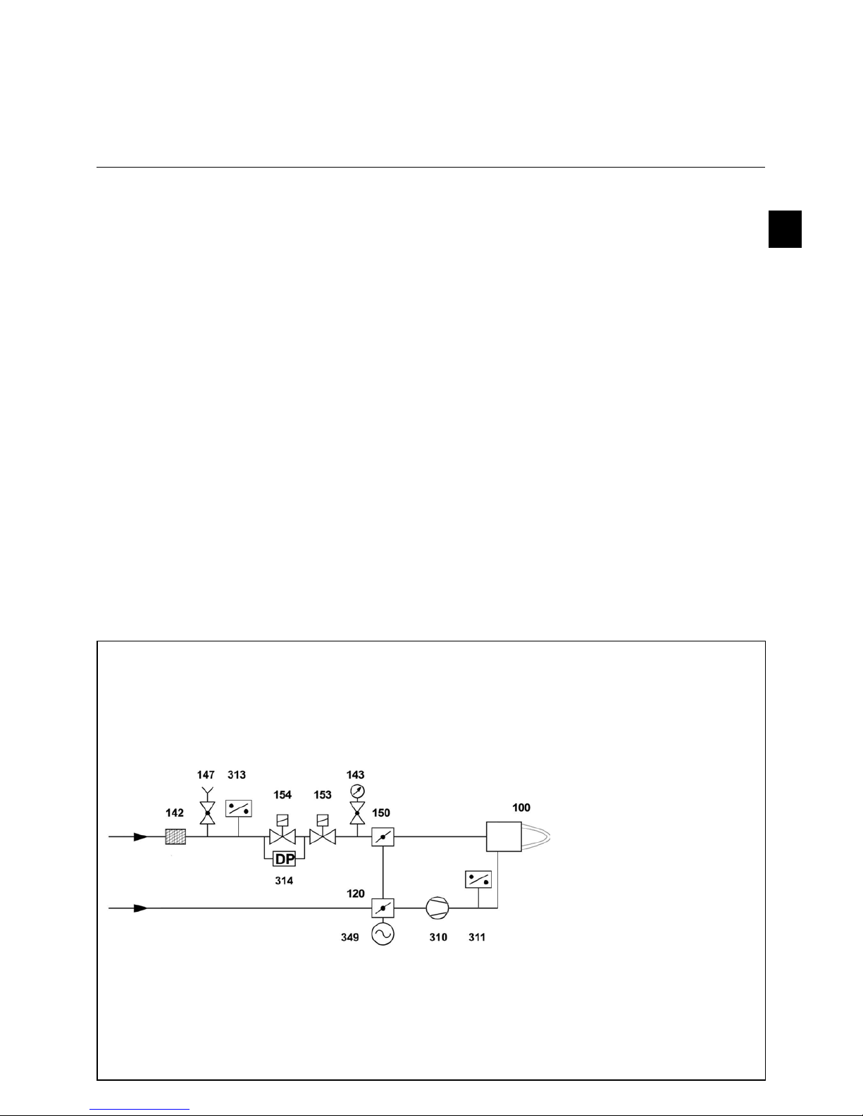
Gas valves and instruments group
The gas valves and instruments group
used with the furnace will be selected
according to the specific requirements to
be met by a burner system.
The following factors must be taken into
account:
• burner output
• furnace back pressure
• gas pressure loss of the burner head
• gas pressure losses of the gas valves
and instruments group
The total gas pressure loss must always
be smaller than the available gas flow
pressure.
NOTE: Use should only be made of gas
valves and instruments that have been
approved in accordance with the burner
test specifications.
100 Burner
120 Air damper
141 Ball valve
142 Gas filter
143 Pressure gauge with stop valve
147 Test burner with stop valve
(optional)
150 Gas damper
153 Main gas solenoid valve
154 Safety solenoid valve
310 Blower
311 Minimum air pressure switch
313 Minimum gas pressure switch
314 Leak test
349 Actuator
Page 6
10/2010 - Art. Nr. 4200 1030 6900A6
O peration
Autom atic furnace contro ller LFL 1.../LG K ...
The LFL 1…/LGK... type controller is
designed to control and monitor burners
working according to a stepwise or
modulating principle. A detailed
functional description with technical data
and project planning information with
respect to the automatic combustion
controllers can be found in the annex
and in the documents:
LFL 1...-7451/LGK...
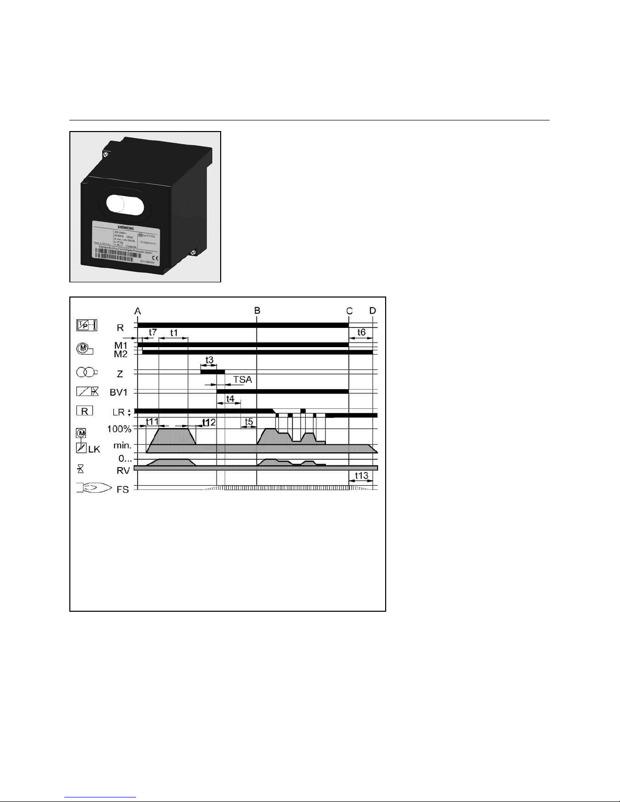
Functional diagram
LFL 1.../LGK...
A = Starting type interval
A-B= Flame development interval
B = Burner has reached operating
position
B-C= Burner operation
(heat generation)
C-D= regular shut-off
t1 Pre-ventilating time
t2 Safety time
t3 Pre-ignition time
t4 Fuel valve enable
t5 Load regulator enable
t11 „OPEN“ run time of air damper
t12 „CLOSE“ run time of air damper
R = Temperature or pressure
controller
M = Fan motor
Z = Ignition transformer
BV= Fuel valve(s)
LR= Load regulator
LK= Air damper
RV= Steadily adjustable fuel valve
FS= Signal of flame
Page 7
10/2010 - Art. Nr. 4200 1030 6900A 7
O peration
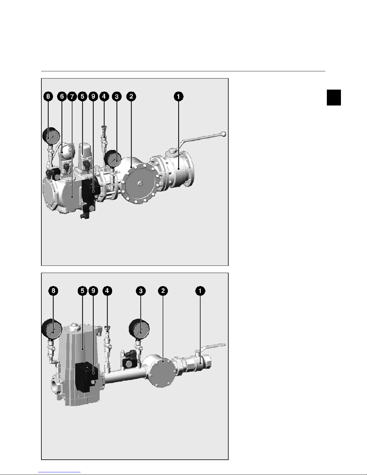
G as valve VG D with SKP actuator
G as valve M BC-SE
Technical data
Input pressure 360 mbar max.
Ambient temperature -15 to +50°C
Voltage 230 V/ 50 Hz max.
Protection rating IP 54
1 Gas ball valve (option)
2 Filter (under the cover)
3 Gas manometer with push button
(upstream) (option)
4 Test burner with push button
(option)
5 Actuator SKP 15
6 Actuator SKP 25
7 Gas main valve VGD..
8 Gas manometer with push button
(downstream) (option)
9 Gas tightness control unit
e
n
Technical data
Input pressure 360 mbar max.
Ambient temperature -15 to +50°C
Voltage 230 V/ 50 Hz max.
Absorbed output (in operation)
250 W max
Protection rating IP 54
1 Gas ball valve (option)
2 Filter (under the cover)
3 Gas manometer with push button
(upstream) (option)
4 Test burner with push button
(option)
5 Compact gas train (safety valve +
main valve)
8 Gas manometer with push button
(downstream) (option)
9 Gas tightness control unit
Page 8
10/2010 - Art. Nr. 4200 1030 6900A8
Assembly
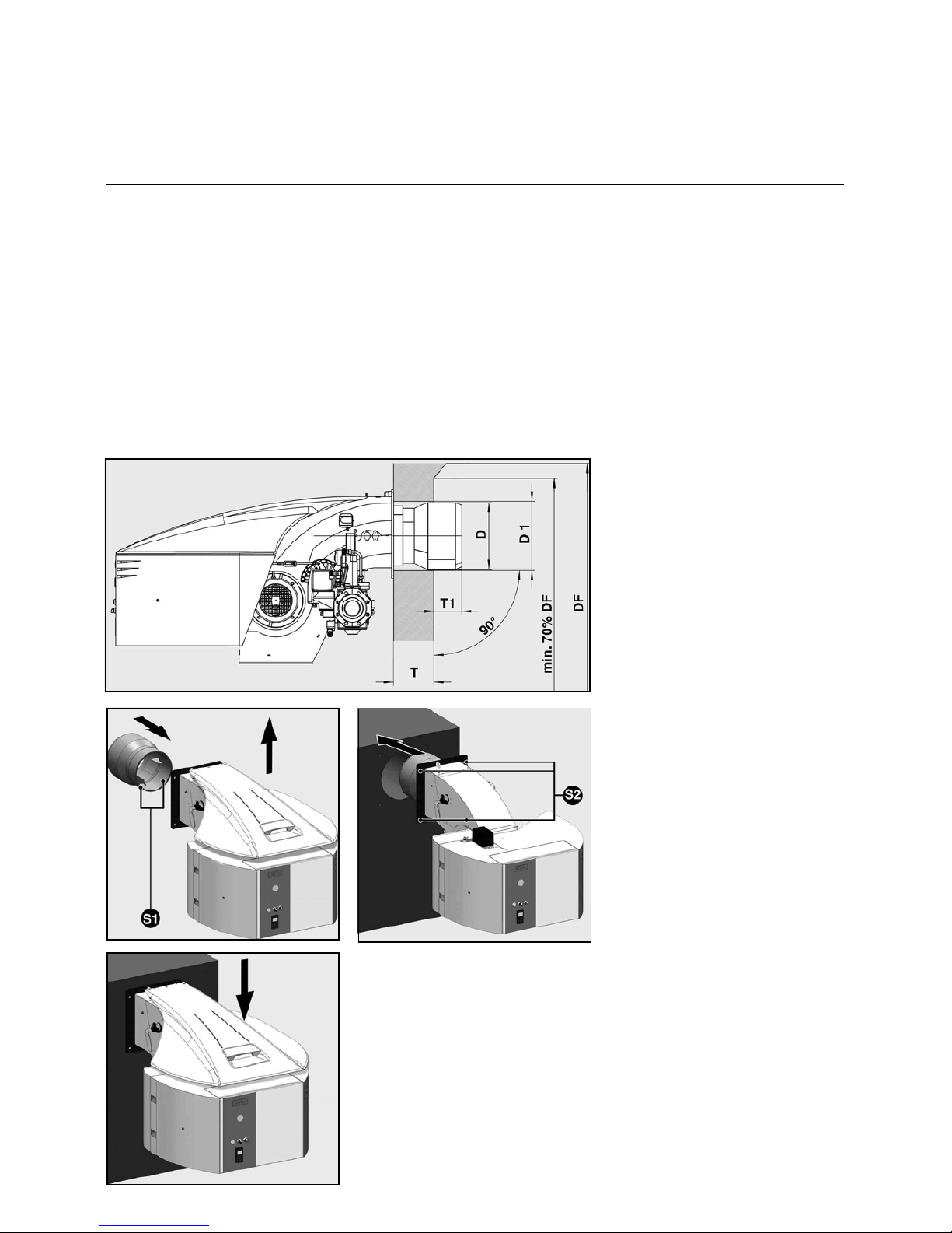
Boiler lining for G-R burner
Burner assembly
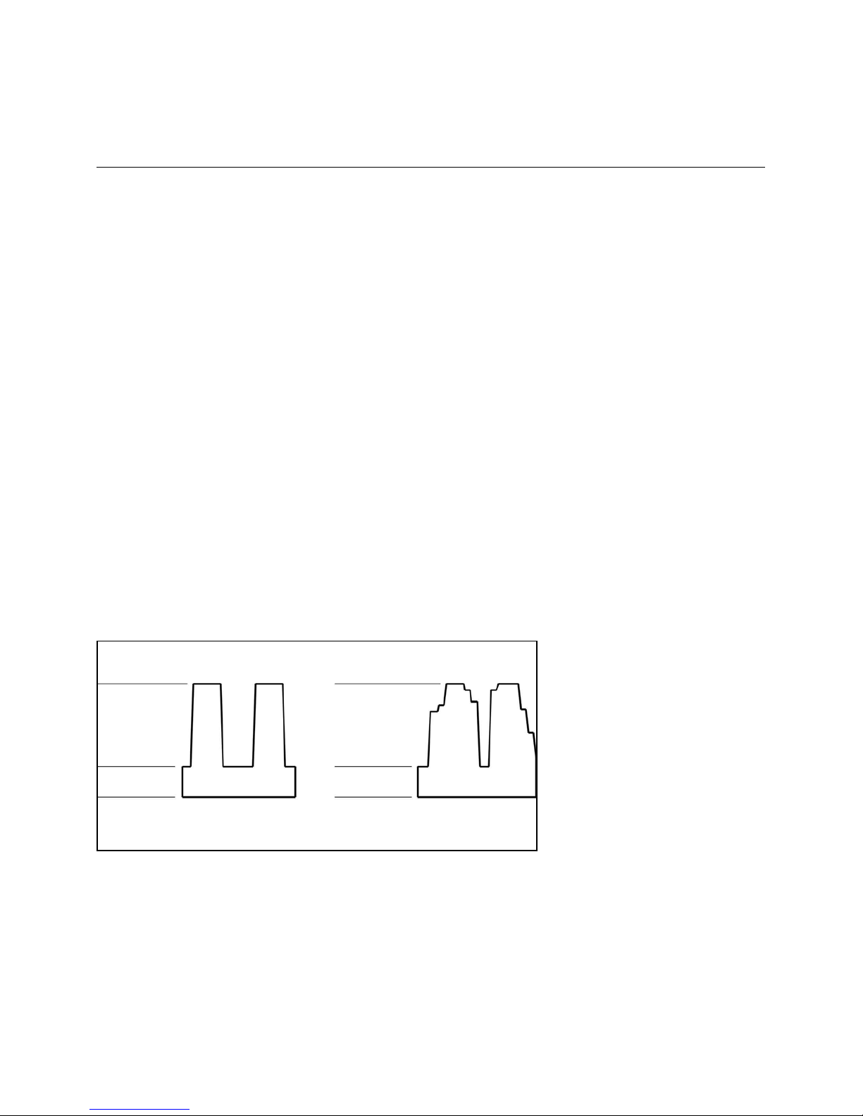
Boiler lining
The burner lining must be installed rightangled to the burner tube. Possible
trimming work (bevelling, rounding) as
required for reverse boilers, for example,
should be done at a diameter not below
70% of the combustion chamber
diameter. The space between the flame
pipe of the burner and the boiler lining
should be lined with heat resistant
material, such as Cerafelt.
This space is not allowed to be lined
with brickwork
Note for reverse flow boilers!
For reverse flow boilers the dimension
T1 is only a recommended value.
Depending on type of boiler the burner
head must stand at least 50 mm ahead
the opening for flue gas turning back.
D = see dimensioned drawings
D1 = see dimensioned drawings
DF = combustion chamber diameter
T1 > 80 mm
T = depth of boiler lining
(option: extensions: see technical data)
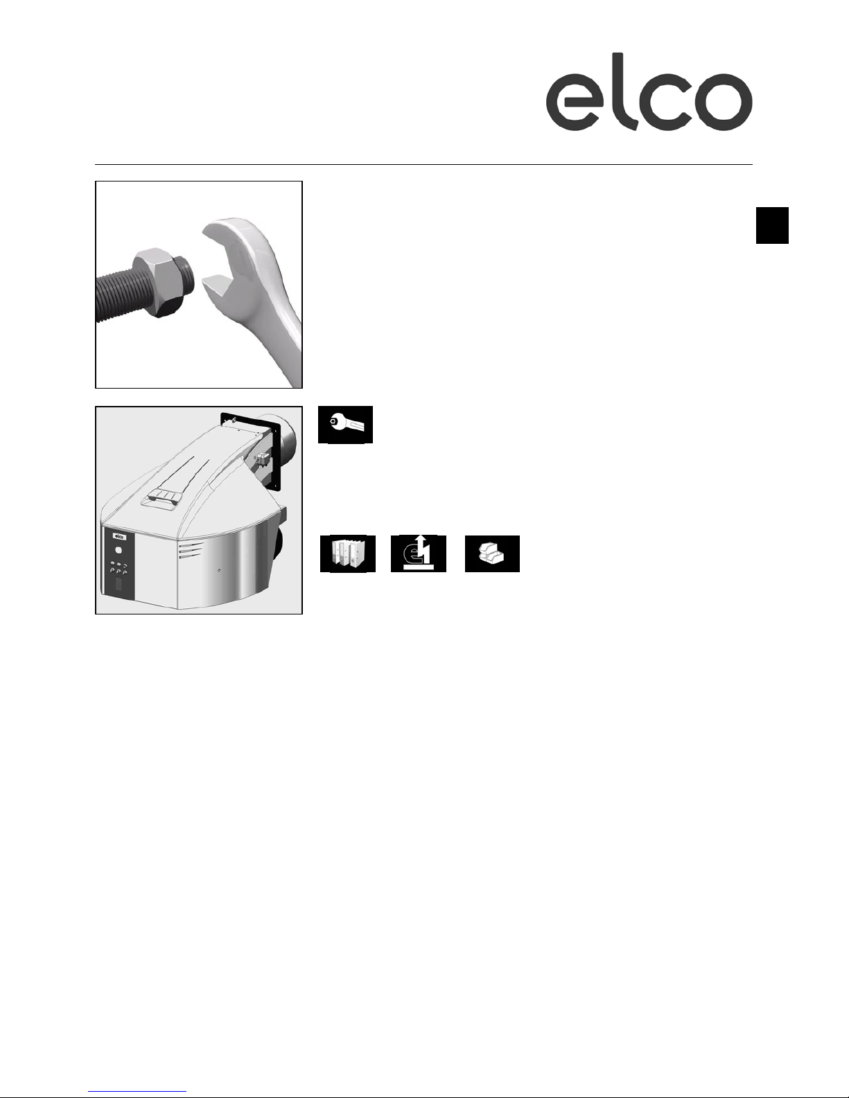
Burner assembly
• Take the burner tube (delivered in a
separate box).
• Fit it on burner body.
• Remove cover.
• Tighten the 2 fixing screws S1.
• Lift the burner, using the 2 hoisting
eyes 19 (see page 3) and fasten to the
boiler.
• Tighten the 4 fixing screws S2.
• Place cover back on.
Page 9

10/2010 - Art. Nr. 4200 1030 6900A 9
Assembly
Gas connection
Gas connection
The gas lines and valves and
instruments group should be installed
and taken into operation in accordance
with the applicable engineering
standards and regulations.
The connection between the gas
distribution network and the gas ramp
must be done by authorised persons.
The section of the pipings must be
calculated so that the loss of load
doesn’t exceed 5% of the distribution
pressure.
A quarter turn manual valve (not
supplied) must be provided for upstream
of the gas ramp and the filter.
The filter must be installed on a
horizontal nozzle with the cover in the
vertical position to enable cleaning.
The threaded unions used must be in
conformity with present standards
(tapered male thread, straight female
thread with sealing provided in the
thread).
Provide for sufficient space to access
the gas pressure switch adjustment.
Gas properties
Prior to any installation work make sure
to obtain the following data from the gas
supply company:
1. type of gas
2. calorific value H
un
=kW/m³ (kJ/m³)
3. maximum CO2 content of exhaust gas
4. gas connection pressure and rest
pressure
Type of gas test
Prior to mounting the burner to the gas
feed line check the available type of gas
and burner type against the data given
on the burner nameplate (attached to
burner). Be sure the description of the
burner and the type of gas are the same
as indicated on the nameplate.
Gas connection pressure
A minimum connection pressure must
be available upstream of the burner gas
valve to ensure the proper functioning of
the burner.
For the installation of the valves and
instruments group take care to observe
the mounting instructions supplied by
their manufacturers (these are packed
with the equipment).
The gas line installed to the burner must
be dimensioned in accordance with the
throughput rate and the available
pressure.
For selecting the nominal bore „DN“ of
the gas valves and instruments group
care should be taken to observe the
flue resistance of the boiler and the
gas pressure loss of the burner and
valves and instruments group.
Caution!
The absence of impurities and foreign
bodies must be checked before
installation and commissioning of the
gas ramp, the lever valves and unions.
Gas valves and instruments group
The gas valves and instruments group
can be connected directly to the gas
feed line. Take care to observe the
correct order of installation and
direction of flow (arrow on housing).
Check the valves and instruments and
connection pieces for absence of dirt
particles and foreign matter before
installation and initial operation. To
provide effective conditions for startup make sure the distance between
the burner and the gas stop valve is
as short as possible.
Leak test
The gas line upstream of the burner gas
valves and instruments group must be
installed in accordance with the
applicable regulations, checked for
absence of leaks, vented and certified
accordingly by the gas installation
company. The screwed unions and
flanged joints must be checked for
proper tightness (by making a pressure
test). The leak test must be made under
pressure using approved foaming
agents which do not cause corrosion.
For steam boiler furnaces the result of
the leak test must be duly certified.
Venting
Caution! Prior to taking the burner into
operation or after any repair work make
sure to vent the complete gas feed line
and the gas valves and instruments
group into the open atmosphere (e.g. by
means of a hose) taking care to avoid
any hazards.
In no case should the gas line be
vented into the heating or furnace
chambers. Make use of a test burner to
check the gas-carrying spaces are free
from an inflammable gas mixture.
Support
The valves and instruments group must
be supported with a telescopic jacking
member or similar during and after
installation (e.g. on filter and valve).
Joint
It is recommended to provide an easytodisconnect joint (with planar sealing
faces) to facilitate repair work on the
boiler (furnace) and allow the boiler door
to be swivelled out if required.
e
n
Page 10

10/2010 - Art. Nr. 4200 1030 6900A10
Assembly
Checking / assembling the combustion components
Burner A B
N6.2400 G-R 19 203
N6.2900 G-R 0 185
N7.3600 G-R 50
234.5
N7.4500 G-R 10
Assembling the combustion
components
• Check that the O-Ring J1 is in the
correct position in the gas elbow.
• Check the adjustment settings of the
ionisation probe and of the ignition
electrode as per the diagrams.
• Insert the combustion components
into the head, tighten the mounting
screws S3.
• Connect the ionisation cable IK and
the ignition cable ZK on the
combustion head.
• Connect the ignition cable ZK on the
ignition transformator T1.
Important
If there is a change to the type of gas
used, for example H or E natural gas
(G20) to L or LL gas ( G25) or vice versa,
the burner settings should be
completely overhauled.
It is not necessary to modify the
combustion head in any way.
Page 11

10/2010 - Art. Nr. 4200 1030 6900A 11
Assembly
Gas connection
Electrical connection
Checks before commissioning
Checks before commissioning
The following must be checked before
initial commissioning:
• That the burner is assembled in
accordance with the instructions given
here.
• That the burner is pre-set in
accordance with the values in the
adjustment table.
• Setting the combustion components.
• The heat generator must be ready for
operation, and the operating
regulations for the heat generator
must be observed.
• All electrical connections must be
correct.
• The heat generator and heating
system must be filled with water and
the circulating pumps must be in
operation.
• The temperature regulator, pressure
regulator, low water detectors and any
other safety or limiting devices that
might be fitted must be connected and
operational.
• The exhaust gas duct must be
unobstructed and the secondary air
system, if available, must be
operational.
• An adequate supply of fresh air must
be guaranteed.
• The heat request must be available.
• Sufficient gas pressure must be
available.
• The fuel supply lines must be
assembled correctly, checked for
leaks and bled.
• A standard-compliant measuring point
must be available, the exhaust gas
duct up to the measuring point must
be free of leaks to prevent anomalies
in the measurement results.
General regulations applying to the
gas connection
• The gas train must only be connected
to the gas mains by a recognised
specialist.
• The cross-section of the gas line
should be of a size designed to
guarantee that the gas flow pressure
does not drop below the specified
level.
• A manual shut-off valve (not supplied)
must be fitted upstream of the gas
train.
• In Germany, a thermally triggered
shut-off valve (to be installed by the
customer side) must be fitted as
specified by the draft combustion
ordinance.
It is the responsibility of the fitter or his
representative to obtain approval for the
system at the same time as the burner is
commissioned. Only the fitter or his
representative can guarantee that the
system meets applicable standards and
regulations. The fitter should be in
possession of the corresponding official
permit, and should carry out the
corresponding sealing tests and purge
the system of air.
All electrical installation and
connection work must only be carried
out by a suitably qualified electrician.
The applicable guidelines and
directives must be observed,
as well as the electrical circuit
diagram supplied with the
burner!
Electrical connection
• Check to ensure that the power supply
is as specified (230V, 50 Hz single
phase with neutral and earth)
Boiler fuse: 10 A
Electrical connection
It must be possible to disconnect the
burner from the mains using an
omnipolar shutdown device complying
with the standards in force.
Burner motor connection
The burner is delivered for a power
supply of 400V - 50Hz of triphase
current with neutral and earth.
Connect the burner motor cable to the
terminals in the electrical cabinet.
Check the direction of rotation of the
ventilation motor manually with the
burner contactor.
Connecting the gas train
Connect the gas train to the plugs on the
burner.
e
n
Page 12
10/2010 - Art. Nr. 4200 1030 6900A12
Commissioning
Burner power adjusting sequence
SQM actuator switch assignment
Description Pre setting Function
I 125° Max. power
(air and gas)
II 5° Closed flaps
(air and gas)
III 20° Gas min.
power
IV - Not used
V - Not used
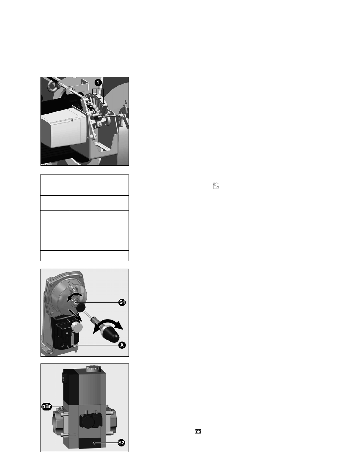
Setting sequence (short description)
• In electrical cabinet, set switch on
"local control / hand" position or
• Adjust min. power switch (minimum
flame power), for example on 20°
• Adjust max. power switch (maximum
flame power) for example on 125°
• Check air shut-off switch (0°)
• Switch burner on
• Air flow-rate setting (min. power).
Screws (Pos. 1) allow the combustion
air flow-rate setting. Rotation to the
left : less air. Rotation to the right :
more air.
• Increase power gradually up to max.
power, either using "higher - lower"
"+/-" switch, either by disengaging the
actuator. During adjustment,
continuously check emissions of CO,
CO
2
and soot!
• Adjustment of max. power by setting
the air flow-rate and adjusting the gas
pressure. Adjust the max. power
switch again. Burner power should
never exceed the max. heat generator
allowed flame power.
(see chapter entitled ’’Exhaust gas test’’)
• Decrease power gradually down to
min. power using "higher - lower" "+/-"
switch, while accurately refining the air
flow according to the new defined gas
pressure.
• Register in a measurement report the
main data (flow rates, power, gas
pressure, air pressure, combustion
values) for at least three power levels
(min. power, intermediate power,
max. power).
• Adjust min. power switch (minimum
flame power) on the desired min.
power.
• Switch burner off
• Set switch on "automatic operation /
remote control" position .
• If fitted : go on with the electrical
modulating power controller setting
Gas pressure setting
Gas train VGD
• Remove protection cap on SKP25
• Set gas pressure pBr using screw S1
(hidden by the cap)
• Check setting : position of the index in
relation with the scale X
Gas train MBC
• Set gas pressure pBr using screw S2
Caution!
Gas output pressure (regulator output
pressure) must be adjusted lower than
the input pressure, but higher than the
total gas pressure loss of the heating
plant.
Q
·
F
Q
·
N
η
--------
=
VGD ..
.
MBC ...
Page 13

10/2010 - Art. Nr. 4200 1030 6900A 13
e
n
Commissioning
Mechanical com pound
Electrical actuator
Limit sw itch setting
Technical data SQM actuator
Voltage 230 V -15%
50 / 60 Hz
240 V +10%
50 / 60 Hz
Power input 9 VA
Max. contact load250 V 10 (3) A
Mounting positionas required
Ambient
temperature -20°C + 50°C
Protection
classification IP 54, DIN 40050
Weight 1,7 kg
SQM10/11 SQM20/21
Running time at
130° turning
angle
42 Sec. 66 Sec.
Torque 10 Nm 20 Nm
Description
The SQM actuator is intended for use
with two-stage sliding or modulating oil,
gas or dual-fuel burners. The reversible
actuator is fitted with a synchronous
motor which drives a shaft via a
gearbox. The shaft end carries a
coupling to drive the fuel and
combustion air controlling element.
The SQM actuator has been designed
for dual-wire control by controller or
switching units with change-over
contacts. Potentiometers can be
installed for a range of applications on
customer's request.
The 60 Hz frequency will reduce the
running times by approx. 17 %.
Limit switch factory setting
Description Pre setting Function
I 125° Max. power
(air and gas)
II 5° Closed flaps
(air and gas)
III 20° Gas min.
power
IV - Not used
V - Not used
The limit and auxiliary switches are set
by means of manually adjustable
latching cam plates. Scales are fitted
between the disks to facilitate the
selection of the switching points.
The cam plates are provided with a
small pointer for indicating the switching
point of a scale between the setting
ranges.
An additional scale fitted to the end of
the cam roller serves to indicate the
position of the actuator.
The drive unit may be disconnected from
the controlling element by changing over
a rocker arm mounted to the gearbox.
This will allow any desired position of the
controller plate to be selected by hand.
Drive and output will be coupled in the
vertical position of the rocker arm.
The fuel-air curve should be set over the
full range of the cam plate so that
operating safety will be retained also
when the limit switch is overrun.
Positions
1 Terminals
2 Cam setting key
3 Scales for switching point setting
4 Rocker arm for uncoupling
5 Scale for actuator position
6 Actuator position indicator
7 Shaft end to fit a return
potentiometer
8 Power supply
Important
A l'issue du réglage des manostats,
ceux-ci doivent être protégés contre tout
dérèglement. Ceci peut par exemple
être réalisé par le marquage, à l'aide
d'un vernis, d'au moins une vis sur le
couvercle de protection des appareils.
A l'issue de la mise en service du
brûleur, il est nécessaire de vérifier le
fonctionnement correct des systèmes
de sécurité du brûleur. De même, après
la mise en service, il est nécessaire de
vérifier le fonctionnement correct de la
chaîne de sécurité de la chaudière par
rapport à la réglementation en vigueur.
Cette vérification doit avoir lieu en
accord avec l'exploitant.
Page 14

10/2010 - Art. Nr. 4200 1030 6900A14
Commissioning
M onitoring of the flam e by ionisation
Sensor c u rre n t m easurem ent
Ionisation monitoring
Detection of the flame using an
ionisation device. Flame detection is
achieved using the conductivity and the
rectification effect of the hot flame
gases. An alternating voltage is applied
to the sensor (in refractory material),
which is dipped into the flame. When a
flame is present, the current (ionisation
current) circulates and forms the flame
signal. This signal is transmitted to the
input of the flame signal amplifier. The
flame signal amplifier is designed to
react only to the continuity of the flame
signal. This eliminates the possibility for
confusion of a potential short-circuit
between the sensor electrode and earth
with a flame signal (as an alternating
current would be used in this scenario).
Use a microammeter to measure the
signal (take into account the
measurement range). This device is
placed between the control box and the
ionisation electrode. Make sure the
polarity of the device is observed (see
connection examples for the control box
LFL 1…/LGK...).
During ionisation monitoring, it is
important that the signal is transmitted
without wastage. The connection cable
must not lie adjacent to a multicore
cable. A soiled sensor electrode bracket
or faulty ceramics encourage leakage
currents, which reduce the flame signal.
The burner (as a counter electrode)
must be earthed in conformity with the
directives. If this is not the case, an
ionisation current cannot flow. Earthing
of the boiler only is often inadequate.
The ionisation current must be
monitored when the burner is set to
ensure combustion hygiene, i.e. when
switching from partial load to full load.
The ionisation current must not fall
below the minimum monitoring current
required. A large drop in the ionisation
current indicates either a lack or an
excess of air. These malfunctions must
be corrected using appropriate
methods. A consistently high ionisation
current indicates a stable flame and the
correct combustion hygiene.
Sensor currents
* See technical data for automatic
furnace controller LFL 1.../LGK...
Automatic
controller
Minimum
required
Maximum
possible
* LFL 1...
LGK...
6 µA-µA
Recommended instrument range:
0 - 150 µA
Page 15

10/2010 - Art. Nr. 4200 1030 6900A 15
e
n
Commissioning
Gas pressure switch
Air pressure switch
Determining the differential preflushing pressure and adjusting the
differential pressure switch
• Burner in the pre-aeration phase.
• Measure pressure on test
connection (2).
• Measure vacuum on test
connection (3).
• Add the measured pressures.
• Set the scale to 90% of the calculated
value.
Switch function test
• Test buttons are provided to check the
switch functions for proper operation
(with safety cut-out and interlock). The
burner is normally run in partial-load
condition when testing the safety
functions. On pressing button (4) the
vacuum will be removed which causes
the differential pressure to drop below
the required level. If it is necessary to
test the pressure switch functions
under full-load conditions this may be
done by pressing button (1).
Gas pressure switch A6
Technical data:
Type of gas:
Gases according to DVGW Worksheet
G 260/1, gas families 1, 2, 3
Degree of protection: IP 54
Ambient temperature: -15°C to +50°C
Mounting position: any
Operating pressure up to:
GW 50/150 A5A6 500 mbar
GW 500/ A5/A6 600 mbar
Gas pressure switch GW...A5/A6
The gas pressure switch is designed to
monitor the gas flow pressure. It can be
used for monitoring either falling
pressure (minimum) or rising pressure
(maximum, specified for equipment
according to TRD 604).
The types GW...A5/A6 may be used as
pressure switches of specific design
according to VdTÜV Leaflet "Pressure
100/1" for application in furnace systems
complying with TRD 604. The setpoint
(switching point) may be selected by
means of a setting disk with scale.
Air pressure switch
The air pressure switch is provided for
monitoring the pressure of the
combustion air fan.
The pressure switch „Dungs“ LGW...
has been designed for switching on, off
or over an electric circuit in the case of
changes of the actual pressure levels
from the setpoint setting. The pressure
switch LGW... can be used as
overpressure, vacuum or differential
pressure monitor for air and nonaggressive gases but not for gases
according to DVGW Worksheet G 260/l.
Certification
The pressure switch has been tested in
accordance with DIN 3398 Part 2 and is
registered by CE/DIN-DVGW. It has
been registered in other important gas
consumption countries.
Important
Once the pressure switches have
been set, they must be protected to
prevent settings from being altered.
For example, this can be done by
placing a spot of varnish on at least
one of the screws on the equipment's
protective cover.
Gas pressure switch A5
Setting the min. gas pressure switch
• Remove the protective cover.
• At the rated output, measure the gas
flow pressure and calculate the
switch-off pressure by reducing by
approximately 20%.
• Adjust the graduated disc to the
desired switch-off pressure opposite
the arrow (the graduations are
approximate values).
• Operate the burner at minimum power.
• Close the gas cut-off valve slowly to
obtain the desired switch-off pressure.
• Turn the graduated disc until the
burner switches off.
• Refit and screw down the protective
cover.
Max. gas pressure switch
• Remove the protective cover.
• At the rated output, measure the gas
flow pressure and calculate the
switch-off pressure by increasing by
approximately 20% (no more than
30% under any circumstances).
• Adjust the graduated disc to the
desired switch-off pressure opposite
the arrow (the graduations are
approximate values).
• Operate the burner at minimum power.
If the max. gas pressure switch
switches off the burner, increase the
adjustment value but not to more than
130% of the flow pressure at the rated
output.
Page 16

10/2010 - Art. Nr. 4200 1030 6900A16
Specifications for the design,
construction and safety features of gas
furnace systems in heating installations
are contained in DIN 4756 and TRD 412.
Heating installations with higher
operating pressures are subject to the
DVGW Worksheets G 460 and G 461.
The gas pipes must meet the
specifications of DVGW-TRGI in the
case of installations with operating
pressures up to 100 mbar or higher
than100 mbar.
Gas connection pressure
To ensure the proper functioning of the
burner, a minimum connection pressure
must be available.
The gas feed pipe to the burner must be
dimensioned according to the
throughput rate and the available
pressure.
The nominal bore (DN) of the gas valves
and instruments group must be selected
on the basis of the resistance of the
boiler on its flue-gas side and the gas
pressure loss of the burner and
valves and instruments group.
Gas valves and instruments group
The gas valves and instruments group
may be connected directly to the gas
supply line. Care should be taken to
install the valves and instruments in the
specified order and according to the
direction of flow (arrow on housing).
Prior to installation and operation, check
the valves and instruments and the
connecting elements for possible
accumulated dirt particles and foreign
matter. To ensure proper conditions
for start-up, the distance between the
burner and the gas shut-off valve
must be as low as possible.
On completion of installation the gas
valves and instruments group must be
subjected to a leak test in accordance
with DVGW Worksheet G 600 and G
490 in the furnace system.
Gas valves and instruments group
Description
Gas valves and instruments group type
VGD
Technical data:
Types of gas:
Gas types of gas families 1, 2 and 3
according to DVGW Worksheet
G 260/1
Max. inlet pressure:
500 mbar
Electrical connection: 230-240V, 50Hz
Protection classification: IP 54
Ambient temperature:
-15°C to +50°C
Description
The gas valves and instruments groups
type VGD (screwed and flanged valves)
are provided for gas supply, main shutoff, gas filtration and gas supply
pressure control and monitoring. They
can be used for all types of gases in the
gas families 1, 2 and 3 according to
Worksheet G 260/1. The valves and
instruments groups are constructed as
specified by EN 676 and DIN 4788, Part
2. All functional parts have been
checked by individual tests and
approved by a CE and DIN-DVGW
registration number.
A detailed description of the valves and
instruments used is contained in the
Technical Datasheet for the Gas Valves
and Instruments Groups Type VGD.
The premounted gas valves and
instruments group is subjected to a leak
test at the manufacturer's works.
For the installation and start-up of the
gas pipes take care to observe the rules
and regulations set forth by DVGW,
especially DVGW-TRGI and TRF.
Page 17

10/2010 - Art. Nr. 4200 1030 6900A 17
e
n
Gas valves and instruments groups
Basic construction
100 Burner
101 Impulse pipe gas pressure
120 Air flap
141 Ball valve
142 Gas filter
150 Gas control butterfly
151 Gas double valve (Siemens system illustrated)
155 Ignition unit
313 Min. gas pressure switch
314 Gas pressure switch for valve leak check or valve leak
checker
349 Actuator
Options in accordance with country-specific requirements:
143 Pressure gauge with pushbutton valve
147 Test burner with pushbutton valve
148 Compensator
154 Gas safety valve (additional)
313a Max. gas pressure switch
The burner's scope of delivery may
include a gas train. In this case, the
burner and the gas train are issued with
a CE Declaration of Conformity. If the
gas train is not delivered with the burner,
the conformity of the burner is valid only
if the gas fittings and instruments and
the design of the gas train satisfy the
burner test specified by EN 676 and
meet the Pressure Equipment Directive.
Individual testing will be necessary
where this is not the case.
The gas train delivered has its own
documentation including operating
instructions and a spare parts list. There
follows a general description of the gas
train.
Gas trains with a double valve are
intended for the supply, main shut-off,
gas filtration, gas pressure regulation
and monitoring of the gas supply. They
are compatible for use with gases
conforming to the specifications of the
gas fittings and instruments. They are
built in accordance with EN 676. All
function parts have been individually
tested and awarded the CE marking and
number of the Notified Body. The
preassembled gas train is checked for
leaks in the factory.
Low- and high-pressure gas trains
If the outlet side of the regulator, i.e.
individual fittings and instruments
downstream of the gas pressure
regulator, has not been designed to be
compatible with the maximum supply
pressure that occurs in the event of a
fault, the gas train must be equipped
with a safety shut-off valve (SSV) and a
safety relief valve (SRV) in accordance
with EN 676. This equipment is
generally required for maximum supply
pressures of >360 mbar and > 500 mbar
respectively. These are known as
highpressure gas trains.
If all fittings and instruments of the gas
train have been designed/approved for
the maximum supply pressure that
occurs in the event of a fault, the gas
train is known as a low-pressure gas
train. This is the case, depending on
component selection, for maximum
supply pressures of 360 and 500 mbar.
Page 18

10/2010 - Art. Nr. 4200 1030 6900A18
Gas valves and instruments groups
Basic construction
100 Burner
101 Impulse pipe gas pressure
120 Air flap
141 Ball valve
142 Gas filter
144 Gas pressure regulator
145 Safety shut-off valve (SSV)
148 Safety relief valve (SRV)
150 Gas control butterfly
151 Gas double valve with integrated gas pressure
regulator (Siemens system illustrated)
155 Ignition unit
313 Min. gas pressure switch
314 Gas pressure switch for valve leak check or valve
leak checker
349 Actuator
Options in accordance with country-specific requirements:
143 Pressure gauge with pushbutton valve
147 Test burner with pushbutton valve
148 Compensator
154 Gas safety valve (additional)
313a Max. gas pressure switch
Gas valves and instruments group
The gas trains must be dimensioned to
suit the throughput required and the
available gas pressure. The gas valves
and instruments group is defined on a
system-specific basis.
The following must be taken into
consideration:
• Burner output,
• Combustion chamber counterpressure,
• Gas pressure loss in the burner head,
• Gas pressure losses in the gas fittings
and instruments.
The total drop in gas pressure must
always be lower than the available gas
flow pressure.
Page 19

10/2010 - Art. Nr. 4200 1030 6900A 19
Gas valves and instruments groups
Basic construction
Installation and mounting of the gas
filter
The gas filter may be installed in any
desired position. Take care only to
observe the direction of flow of the gas
(arrow on filter housing). Make sure
there is adequate clearance to facilitate
the removal of the cover and
replacement of the filter cartridge.
Filter replacement
The filter cartridge should be replaced
by a new one as soon as a high pressure
drop is noticed. If a new filter cartridge is
not at hand it will be possible to wash the
filter mat in 40°C water adding some
light-duty detergent. Allow the mat to dry
before reinstallation.
NOTE: For the installation of the filter
mat take care to observe the marking or
sticker.
e
n
Test burner
Depending on the country-specific
requirements, when installing steam
boilers it may be necessary to fit a test
burner to the gas train (e.g. in line with
directive TRD 412). This is used to vent
the gas pipes. The gas supply is
switched on by pressing the button (1).
The flow of gas brings in the required
amount of combustion air via the hole in
the body (3). The gas/air mixture is
routed towards the burner head (4) and
ignited manually at its opening. Gas is
supplied for as long as the button is
pressed and cut off when it is released.
Technical features:
• Types of gas:
Gas in accordance with sheet G 260/1
of the DVGW, gas families 1, 2, 3
• Ambient temperature: -15°C to +70°C
• Assembly position: vertical, facing
upwards
• Operating pressure up to: 500 mbar
Page 20

10/2010 - Art. Nr. 4200 1030 6900A20
Gas valves and instruments group
Gas valve leakage controller
Leakage controller VPS 504 S02
Working principle :
Prior to each burner start-up, the
controller checks for possible leaks
between safety and main valves by
increasing distribution pressure.
Electrically, the leakage controller is
serially connected between the
thermostatic circuit and burner control
and safety unit.
Installation :
Directly on valve.
Program stages :
On stoppage, safety and main valves
are closed.
On thermostat stoppage, the leakage
controller is turned on and booster
increases distribution pressure by
20mbar.
After no more than 30 seconds
operation :
- If leakage test is OK; yellow light
comes on and current is released to
feed the burner’s control and safety
unit, which then starts its cycle.
- If leakage test is NOK; red light comes
on and no power is fed to the control
and safety unit.
Control cycles have to be restarted
manually. Change valve if defect
persists.
Setting :
The controller requires no on-site
setting.
Working test :
While controller is working :
• Open pa pressure take-off. Leak
caused prevents superpressure from
building up and safety unit locks after
30 seconds.
• Reclose pa pressure take-off.
• Release controller safety by pressing
red indicator light.
Leakage test restarts and, after 30
seconds, yellow indicator lights up and
powers up the control and safety unit,
which begins its cycle.
1 Wieland 7P socket
3 Filter element
4 O-ring Ø10.5x2.25
5 Fuse T6.3 250V Ø 5x20
6 Yellow indicator On :
Leakage test OK
7 Red indicator On :
Leakage test NOK
Manual clear
8 Spare fuses
9 pa (p2) pressure take-off Ø 9
pe + 20mbar
10 pe (p1) pressure take-off Ø 9
i nlet pressure (distribution)
Page 21

10/2010 - Art. Nr. 4200 1030 6900A 21
Servicing
Maintenance
Burner and boiler servicing must only
be carried out by a professionally
qualified heating engineer. The system
operator is advised to take out a
maintenance contract to guarantee
regular servicing. Depending on the
type of installation, shorter
maintenance intervals may be
necessary.
1. Turn off the power supply and protect
the system from accidental start-up.
2. Cut the gas supply.
3. Make sure there is no residual power in
the system and that the actions in points
1 and 2 have been completed.
4. Before opening the burner casing,
ensure that the fan motor has stopped
completely.
Failure to observe any of these
instructions will result in the risk of
death or injury!
• Use original spare parts.
Work recommended as part of annual
burner maintenance:
- Burner test run, input measurement in
the boiler room
- Clean the combustion components
and replace defective parts if
necessary
- Clean the fan wheel and the blower
- Clean the gas filter; replace it if
necessary
- Visual inspection of the burner's
electrical components; eliminate
malfunctions if necessary
- Check burner start characteristics
- Leakage test
- Burner safety devices function check
(air pressure/gas pressure switches)
- Flame monitor and automatic
combustion control unit function check
- Commissioning the burner
- Check the gas flow
- Correct the adjustment values if
necessary
- Draw up a measurement report
General checks
- Emergency stop button function check
- Visual inspection of gas lines in the
boiler room
Checking the combustion
components
• Loosen the 2 screws S to remove the
burner hood.
• Remove the 7 screws W to remove the
combustion components access
cover.
• Remove the combustion components.
• Check the ignition electrodes and the
ignition cable; replace if necessary.
• Clean the baffle plate.
• Check adjustments and settings
during assembly.
Cleaning the fan
• Disconnect the motor by unplugging it
from the power supply.
• Remove the motor.
• Thoroughly clean the fan.
• Do not use pressurised materials.
• Reassemble.
e
n
Page 22

10/2010 - Art. Nr. 4200 1030 6900A22
Servicing
Maintenance
Filter replacement
• The filter element of the must be
checked at least once a year and
replaced if clogged.
• Loosen the screws of the filter cap.
• Remove the filter element and clean its
housing.
• Do not use any pressurised cleaning
products.
• Replace the filter element with a new
element.
• Screw the cover back into place.
• Reopen the manual shut-off valve.
• Check it is airtight.
• Check the combustion values.
Cleaning the cover
• Do not use abrasive products or
products containing chlorine.
• Clean the cover with water and a
suitable cleaning product.
• Refit the cover.
Precautions
After any operation: check the
combustion performance under real
operating conditions (doors shut,
cover fitted etc.). Record the results
in the relevant documents.
Important
Once the pressure switches have
been set, they must be protected to
prevent settings from being altered.
For example, this can be done by
placing a spot of varnish on at least
one of the screws on the equipment's
protective cover.
Following maintenance on the
burner, and after its safety system
settings have been modified (e.g. the
pressure switches), the burner's
safety systems must be checked to
ensure they are operating correctly.
Likewise, following burner
maintenance, it is necessary to check
that the boiler's safety chain is
operating correctly in accordance
with the regulations in force. This
check must be carried out with the
user's agreement.
Checking the flue gas temperature
• Check the flue gas temperature at
regular intervals.
• Clean the boiler if the flue gas
temperature is more than 30 °C above
the value measured at the time of
commissioning.
• Use a flue gas temperature gauge to
make the check easier.
Page 23

10/2010 - Art. Nr. 4200 1030 6900A 23
Servicing
Exhaust gas test
Trouble shooting instructions
Exhaust gas loss
Exhaust gas loss by way of free heat will
occur as a result of the temperature
difference between the fuel-air mixture
entering the furnace chamber and the
gases discharged. Any increase in the
excess of air and the resultant higher
exhaust gas volume will cause the
exhaust gas loss to rise. The exhaust
gas loss can be calculated as follows:
q
A
= exhaust gas loss in %
t
A
= exhaust gas temperature in °C
t
L
= combustion air temperature in °C
CO
2
= volumetric content of carbon
dioxide in %
O
2
= volumetric content of oxygen
in %
q
A
tAt
L
∠()
A
1
CO
2
------------B+
⋅=
In any case of trouble proceed with
checking the basic conditions for a
proper operation of the boiler
system:
1. Is electric power available?
2. Is ther any gas pressure?
3. Are the shut-off valves opened?
4. Are all control and safety instruments
such as boiler thermostat, water
supply failure cut-out, limit switches,
etc. properly set?
1. Ignition failure
Cause Remedy
Ignition
electrode short
circuit.
Adjust
electrodes.
Wide ignition
electrode
spacing.
Adjust
electrodes.
Dirty and wet
electrodes.
Clean
electrodes.
Cracked
insulator.
Replace
insulator.
Defective
ignition
transformer.
Replace
transformer.
Defective
automatic
furnace
controller.
Replace
controller.
Burnt ignition
cable.
Replace cable;
search for cause
and eliminate.
Pilot burner
failure.
Adjust ignition
gas pressure
Ignition gas
valve does not
open.
Search for cause
and eliminate
Defective
solenoid.
Replace
2. Motor running failure
Cause Remedy
Motor protection
relay and fuses.
Check and
replace if
required.
Air pressure
switch not
changed over or
defective.
Check and
replace if
required.
Defective motor. Replace motor.
Defective power
contactor.
Replace
contactor.
Air fan motor
starts but stops
after 20-25 secs.
Check for
solenoid leaks
Air fan motor
starts, but stops
after about 10
secs in preventilating mode.
Air pressure
switch fails to
change over;
replace switch if
defective; clean
switch if dirt has
accumulated;
check electrical
connections.
3. No response to flame by
automatic furnace controller
with flame sensor
Cause Remedy
Dirty flame
sensor.
Clean flame
sensor.
Burner fails to
start.
Check
connection of
automatic
furnace
controller.
Trouble lamp
lights; flame
trouble.
Unlock and
search for cause
Ionisation
current too
weak.
Check
combustion
setting.
Burner starts
without flame
formation.
Solenoid valve
fails to open.
Defective coil or
rectifier.
Check
connection.
Lack of gas or
gas pressure too
low.
Check gas
pressure
controller, gas
valve, gas filter.
Is the equipment
gas cock open?
Example:
Data measured in natural gas mode:
CO
2
content of exhaust gases 10,8%
Exhaust gas temperature 195°C
Air intake temperature 22°C
The exhaust gas loss can be calculated
as follows:
Natural
gas
Town
gas
L.P.G.
A
1
= 0,370 0,350 0,420
B = 0,009 0,011 0,008
e
n
Page 24

10/2010 - Art. Nr. 4200 1030 6900A24
Servicing
Exhaust gas test
Trouble shooting instructions
6. Cleaning and lubricating
instructions
Depending on the amount of dirt
introduced by the combustion air it will
be necessary to clean the fan impeller,
ignition electrodes, flame sensors and
air dampers as required.
For burner with mechanical compound
controller:
Lubricate the compound controller
setting screws with grease.
The bearing points of the burner moving
parts require no maintenance. Damages
of ball bearings should be detected and
eliminated at an early stage to avoid
greater subsequent trouble. Listen to the
motor bearing noise to identify possible
irregularities.
4. Mixing unit gives poor
combustion data
Cause Remedy
Incorrect
settings.
Correct settings.
Incorrect mixture
ignition unit.
Replace unit.
High or low
combustion air
flow rate.
Readjust burner.
Furnace
chamber not
sufficiently
ventilated.
Furnace
chamber to be
ventilated
through a nonclosed opening
with a cross
section of min.
50 % of all
chimney cross
sections of the
furnace system.
Take care to
observe the
application
regulations.
5. Solenoid valve fails to open
Cause Remedy
Defective coil or
SKP actuator.
Replace coil or
SKP actuator.
Defective
automatic
furnace
controller.
Replace
automatic
furnace
controller.
Valve does not
close tightly; dirt
accumulated on
sealing surfaces.
Open valve;
remove foreign
matter; replace
valve if required.
Page 25

10/2010 - Art. Nr. 4200 1030 6900A 25
Servicing
Operating trouble
In case of operating trouble it should
be checked whether the system is in
proper working order.
Make a check for the following:
1. Availability of fuel. Availability of gas
in the line at sufficiently high
pressure. Availability of fuel oil in the
tank (for dual fuel burner). Correct
position of fuel selector switch.
2. Availability of electric power in the
burner system.
3. Proper functional order and setting of
all control and safety instruments
such as temperature controller,
safety limiter, water failure cut-out,
electrical limit switches, etc. If the
trouble is not found to be due to any
of the above-mentioned points it will
be necessary to test the burner
functions very carefully.
Prevailing conditions:
The burner will be found to be out of
operation and in faulty and interlocked
position.
Proceed with searching for the cause of
the trouble and eliminate it. Unlock the
automatic furnace controller by pressing
the fault eliminate key and start the
burner.
Do not press the fault eliminate key
longer than 10 seconds.
The start-up program will be initiated
and should be carefully monitored.
The possible cause of the fault may be
quickly found by reference to the fault
indicator of the automatic furnace
controller and watching the start-up and
operating program.
Control program in the case of
trouble and fault indicator LFL 1... /
LGK...
a - b Starting program.
b-b' In a number of time versions; idle
steps of the program unit to selfstop after burner start-up
(b' = operating position of program
unit).
b(b')-aAfter-flushing program after
regular stop. In the starting
position „a“ the program unit will
automatically stop or initiate an
immediate restart of the burner,
e.g. after a fault has been
eliminated.
• Duration of the safety period for
single-tube burners.
•• Duration of the safety period for
burners with ignition gas valve.
Basically, any type of trouble will
result in the immediate stop of the
fuel supply. At the same time, the
program unit and consequently the fault
indicator will stop. The type of trouble
can be identified by the symbol opposite
to the reading mark of the indicator:
No start, e.g. because the
„CLOSED“ signal from the „Air
Damper CLOSED“ limit switch is
missing or a contact is not closed
between terminals (12) and (4) or
(4) and (5); or the contacts of all
control and safety units in the
controlled system are not closed
(e.g. gas pressure or air pressure
switches, temperature or pressure
switches, temperature or pressure
regulators).
Operating stop because the
„OPEN“ signal from the „Air
Damper OPEN“ limit switch is
missing. Check and adjust the limit
switch concerned.
Shut-off on trouble because
there is not air pressure signal at
the beginning of the air pressure
check. Any air pressure failure
after this time will also lead to a
shut-off on trouble.
I Shut-off on trouble because of a
fault in the flame monitoring circuit.
Operating stop because the
position signal of the „Partial Load“
limit switch (air damper in „Partial
Load“ position) is not available on
terminal (8). Check and adjust the
limit switch concerned.
1 Shut-off on trouble because a
flame signal is not available on the
expiry of the (1st) safety time.
Any failure of the flame signal on the
expiry of the safety time will also lead
to a shut-off on trouble.
2 Shut-off on trouble because the
flame signal has not occurred on
the expiry of the (2nd) safety time
(flame signal of main flame with
burners having an ignition gas
valve).
Shut-off on trouble because the
flame signal failed during burner
operation or a lack of air has
occurred.
Shut-off on trouble during or after
the control program flow due to
external light (e.g. by flame not
extinguished, leaking fuel valves)
or a faulty flame signal (e.g. fault in
flame monitoring circuit, or similar);
see flame monitor.
If the shut-off on trouble occurs at
any other time between start and preignition that is not identified by a
symbol as above, this will normally
be due to an early flame signal which
is considered to be a faulty flame
signal.
The automatic furnace controller may
be unlocked immediately after a shut-
off on trouble using the unlock button
with integrated fault signal lamp or an
external switch. After it has been
unlocked (and after a defect with
resultant operating stop has been
eliminated and after a voltage failure),
the program unit will in any case return
to its starting position with voltage being
only supplied to terminals 7, 9, 10 and
11 as preset by the control program. It is
only at this stage that the program of the
automatic furnace controller will restart
the burner.
LFL 1.../LG K ...
e
n
Page 26

10/2010 - Art. Nr. 4200 1030 6900A26
Page 27

10/2010 - Art. Nr. 4200 1030 6900A 27
Page 28

10/2010 - Art. Nr. 4200 1030 6900A28
Made in EU.
Non contractual document.
www.elco.net
Hotline
ELCO Austria GmbH
Aredstr.16-18
2544 Leobersdorf
0810-400010
ELCO Belgium nv/sa
Z.1 Researchpark 60
1731 Zellik
02-4631902
ELCOTHERM AG
Sarganserstrasse 100
7324 Vilters
0848 808 808
ELCO GmbH
Dreieichstr.10
64546 Mörfelden-Walldorf
0180-3526180
ELCO Italia S.p.A.
Via Roma 64
31023 Resana (TV)
800-087887
ELCO Burners B.V.
Amsterdamsestraatweg 27
1411 AW Naarden
035-6957350
OOO «Ariston Thermo RUS LLC»
Bolshaya Novodmitrovskaya
St.bld.14/1 office 626
127015 Moscow -Russia
+7 495 783 0440
 Loading...