

elco N6.2400 GL-RZ3/LFL, N6.2900 GL-RZ3/LFL, N7.3600 GL-RZ3/LFL, N7.4500 GL-RZ3/LFL Operating Instructions Manual
Page 1
09/2011 - Art. Nr. 4200 1040 7900A
N6.2400 GL-RZ3/LFL
N6.2900 GL-RZ3/LFL
N7.3600 GL-RZ3/LFL
N7.4500 GL-RZ3/LFL
............................................. 4200 1035 0600
Operating instructions
For specialist installation engineers
Dual fuel burners
de ......................................... 4200 1035 0500
fr ........................................... 4200 1040 8000
it ........................................... 4200 1041 4900
nl .......................................... 4200 1041 5000
Page 2

09/2011 - Art. Nr. 4200 1040 7900A2
General information
Contents
General information Contents ............................................................................................................................ 2
Important notes .................................................................................................................3
Burner description ............................................................................................................. 4
Installation General information regarding burner assembly ............................................................... 5
Boiler lining for GL-RZ3/LFL burner ..................................................................................6
Burner assembly................................................................................................................7
Burner head setting data GL-RZ3/LFL ..............................................................................8
Gas train
Gas train description .............................................................................................. 9
Basic design....................................................................................................... 10
Description of gas train with MBC... .....................................................................11
Description of Dungs MBC double gas valve... (gas multiblock)..........................12
Changing MBC-300-700-1200 filter ..................................................................... 13
Setting MBC-300-700-1200-SE pressure regulating component ....................... 13
Setting MBC-1900-5000-SE pressure regulating component .............................14
Description of double gas valve VGD... with servomotors SKP ........................... 15
Gas filters ............................................................................................................ 16
Gas/air pressure switch...................................................................................... 17
Leakage controller, test burner............................................................................ 18
Hydraulics
General information regarding fuel oil system, fuel oil hydraulics diagram ......... 19
Fuel oil pressure switch ....................................................................................... 20
General information regarding fuel oil system .....................................................21
Pump...............................................................................................................22-25
Nozzle line 3-stage..........................................................................................26-27
Commissioning Control and safety unit LFL 1.../LGK... ............................................................................ 28
Electrical servomotor..................................................................................................29-30
Flame monitor, probe current measurement .............................................................31-32
Connecting the gas train, electrical connection, checks before commissioning.............. 33
Gas connection................................................................................................................ 34
Fuel-air coupler control....................................................................................................35
Design of switch cabinet door.......................................................................................... 36
Dual fuel load regulator ..............................................................................................37-38
Control .............................................................................................................................39
Preventilation................................................................................................................... 40
Fuel oil start-up mode, fuel oil operating mode ............................................................... 41
General safety functions..................................................................................................41
Gas start-up mode, gas operating mode......................................................................... 42
General safety functions..................................................................................................42
Servicing Maintenance ..............................................................................................................43-45
Checking, assembling the combustion components ....................................................... 45
Setting for ignition electrodes .......................................................................................... 46
Exhaust gas analysis..................................................................................................47-48
Diagnosing and remedying faults ...............................................................................49-50
Faults .............................................................................................................................51
Declaration of conformity ...........................................................................................52-53
Page 3

09/2011 - Art. Nr. 4200 1040 7900A 3
Important information
Burners
N6 and N7 GL-RZ3/LFL
are
designed for the combustion of natural
gas and light oil. The design and
function of the burners comply with
EN676 and EN 267. They are designed
for use with systems that are approved
for the use of burners in accordance with
EN 676 and EN 267.. To use the burner
with heat generators in conformity with
Pressure Equipment Directive 97/23/
EU, special burner components are
required (not supplied with standard
equipment). Before using the burner
with equipment of this type, the
equipment characteristics must be
checked. Burners that comply with
Pressure Equipment Directive 97/23/EU
come with a declaration of conformity to
this effect and are labelled on the identification plate. Any other type of application requires the approval of ELCO. The
burner may only be used in accordance
with the instructions set out in this documentation and the relevant technical
data. If not used properly, it could cause
damage to property and the environment and personal injury. Furthermore,
the burner would no longer be CE compliant. Installation, commissioning and
maintenance may only be carried out by
authorised specialists and all applicable
guidelines and regulations must be
complied with.
Burner description
The burners
N6 and N7 GL-RZ3/LFL
are
progressive, fully automatic mechanical
monoblock-type burners for gas and 3stage for fuel oil. Emissions rates may
differ, depending on combustion
chamber dimensions, combustion
chamber load and the furnace (threepass boilers, boilers with reverse firing).
For specifying warranty values, the conditions for the measuring equipment, tolerances and humidity must be observed.
Scope of delivery
The burner is supplied packaged in
three boxes on a pallet:
- Burner with:
- integrated switch cabinet
- flange seal and securing screws
- operating instructions, circuit
diagram and spare parts list
- Burner head
- Compact gas train with gas filter
Before commissioning, a check must be
carried out to ensure that the product
delivered complies with the scope of
delivery.
The following standards should be
observed in order to ensure safe, environmentally sound and energy-efficient
operation:
EN 226
Connection of fuel oil and forceddraught gas burners with fan to a heat
generator
EN 60335-1, -2-102
Specification for safety of household
and similar electrical appliances, particular requirements for gas burning appliances
DIN EN 60204-1
Safety of machinery. Electrical
equipment of machines
DIN EN 50156-1
Electrical equipment for furnaces
Gas lines
When installing the gas lines and trains,
the general directives and guidelines, as
well as the following national regulations, must be observed:
CH: - SVGW-Gasleitsätze G1
- Vorschriften der kantonalen
Instanzen (SVGW Gas Direc tives G1 - Cantonal specifi cations) (e.g. fire authority
specifications)
DE: - DVGW-TVR/TRGI
Installation location
The burner must not be used in rooms
with aggressive vapours (e.g. hair spray,
tetrachloroethylene, carbon tetrachloride), high levels of dust or high air
humidity (e.g. laundry rooms). The limitations of use set out in the technical
data must be complied with.
Adequate provision must be made for
the supply of combustion air. Given
standard conditions, the combustion air
requirement may be calculated as
follows:
Vl [Nm³/h] = QF [kW] *1.25 [Nm³/(h*kW)]
We can accept no warranty liability
whatsoever for loss, damage or injury
caused by any of the following:
- inappropriate use
- incorrect installation and/or repair on
the part of the buyer or any third party,
including the fitting of non-original
parts
Final delivery and instructions for
use
The furnace fitter must supply the
operator of the system with operating
and maintenance instructions on or
before final delivery. These instructions
should be displayed in a prominent
location at the point of installation of the
heat generator. They should include the
address and telephone number of the
nearest customer service centre.
Notes for the operator
The system should be inspected by a
specialist at least once a year. It is
advisable to take out a maintenance
contract to guarantee regular servicing.
Warning:
When in operation, the burner produces
an electromagnetic field. In certain circumstances, this field could affect
medical implants (e.g. pacemakers).
Before working with the machine,
anyone who has a medical implant
should consult their doctor and the manufacturer of the medical implant in order
to reduce the risk of serious or fatal
injury.
Transport \ packaging \ storage
Safety measures
The burner and accessories must be
transported and stored using suitable
lifting equipment, means of transport
and tools. The safety instructions must
be complied with.
Transport
Depending on the size and weight of
packaging, burners and accessories
must be transported manually or with the
use of suitable aids. The transport
instructions on the packaging must be
complied with. The burner must be
properly secured for transport. If
measures to secure the burner have not
been taken at the factory, suitable
measures to secure it during transportation must be taken.
Packaging
The burner and accessories are placed
on a wooden pallet and shrink-wrapped.
When unpacking the product, suitable
lifting equipment and tools must be used
to remove the screw connections and
clamping devices between the burner
and the packaging. Suitable protective
clothing must be worn (gloves, safety
shoes).
Storage
In order to protect the burner from environmental influences, it must be placed
in a dry, locked room when stored temporarily. For the maximum storage temperatures, please refer to the technical
data sheet.
Disposal
The current local legislation must be
complied with without
fail.
General information
Important notes
Page 4
09/2011 - Art. Nr. 4200 1040 7900A4
General information
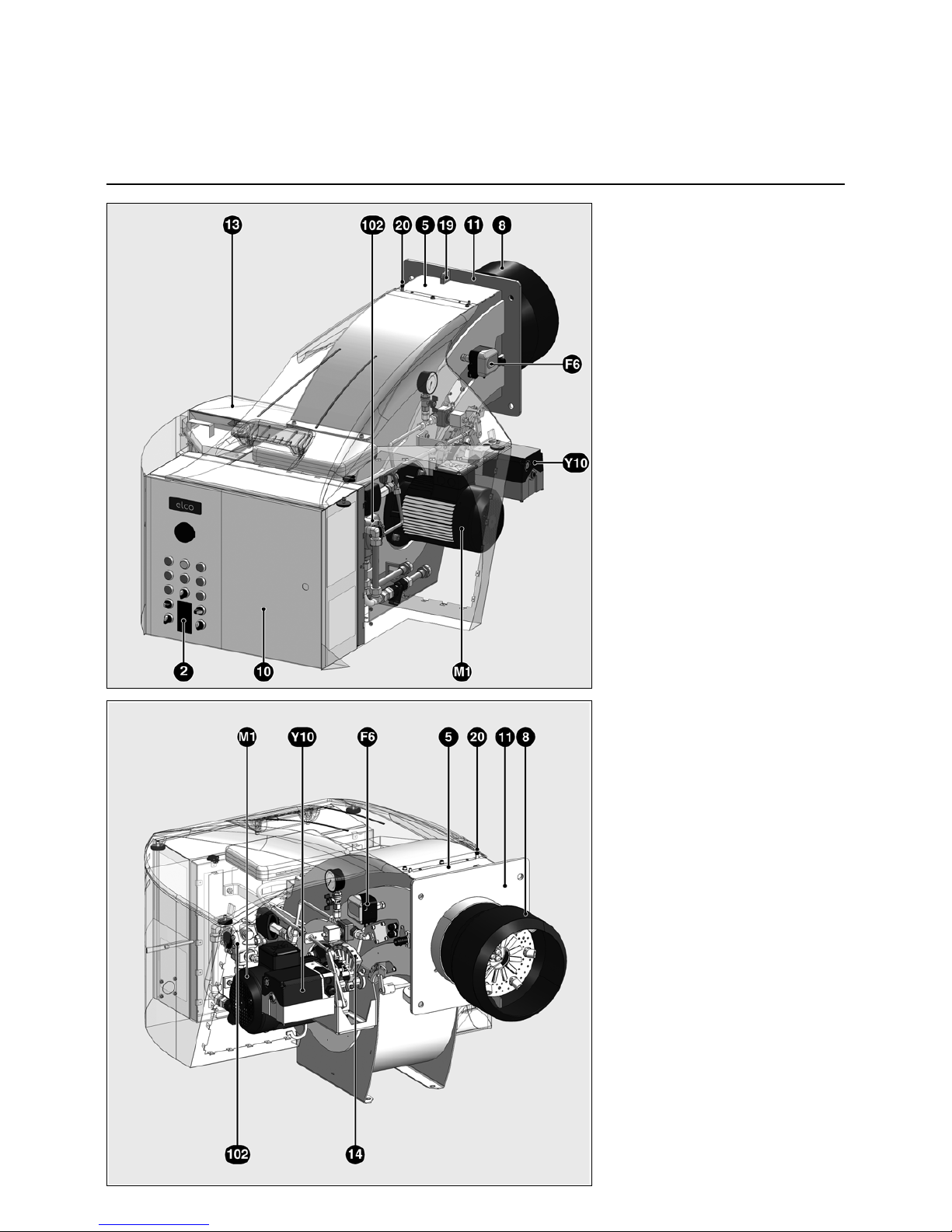
Burner description
2 Load regulator (option)
5 Body
6 Gas inlet flange
8 Burner tube
10 Integrated switch cabinet
11 Burner fixing flange
13 Air intake box
14 Mechanical coupler
19 Hoisting eyes
20 Connector for inspection glass
cooling
F6 Air pressure switch
M1 Fan motor
Y10 Servomotor for air and gas flaps
102 Pump
Page 5
09/2011 - Art. Nr. 4200 1040 7900A 5
Installation
General information regarding burner assembly
Tightening torques
During installation, commissioning and
maintenance, the following torques for
unions must be complied with.
Recommended tightening torques
Standard unions
M4 M5 M6 M8 M10 M12 M16 M20
2 6 10 25 48 85 210 415 Nm
N.B.:
In general, the correct tightening torques have been applied when the unions are
tightened hand-tight using a screwdriver (ISO 272) or angled Allen key.
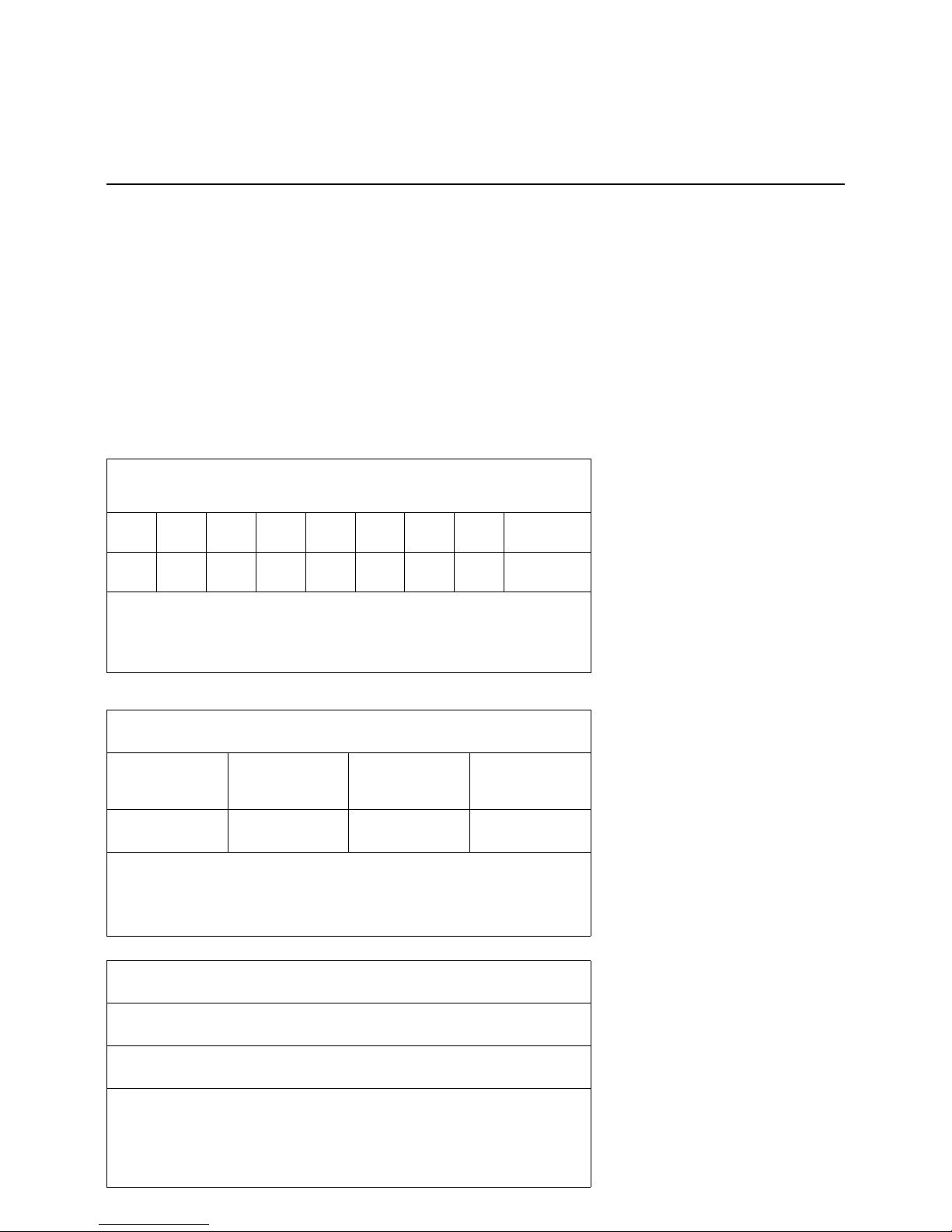
Tightening torques for root connector for fan impeller
SM16 (Ø28)
No.: 1615
SM20 (Ø38 and 42)
No.: 2012
SM25 (Ø42 and 48)
No.: 2517
Bushing
20 30 50 Nm
N.B.:
For more information regarding installation/dismantling of the fan impeller, please
refer to the relevant chapter in the operating instructions.
Tightening torque for gas train flange connector
M16 / DN 65 - DN 125
Max. 50 Nm
N.B.:
The unions must be tightened crosswise. The union must be checked to ensure it
is tight. If it is not sufficiently tight, the fitting must be removed and checked (tightening surfaces).
Page 6
09/2011 - Art. Nr. 4200 1040 7900A6
Installation
Boiler lining for GL-RZ3/LFL burner
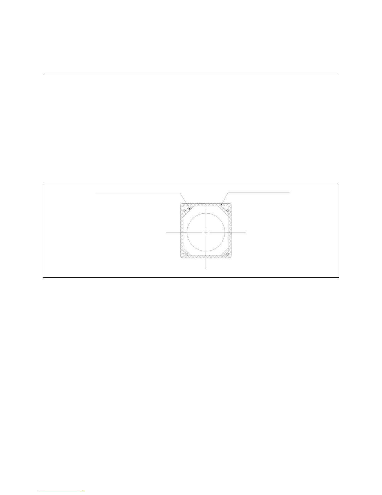
Boiler lining
The burner lining must be installed rightangled to the burner tube. Possible
trimming work (bevelling, rounding) as
required for reverse boilers, for example,
should done at a diameter not below
70% of the combustion chamber
diameter. The space between the flame
tube of the burner and the boiler lining
should be lined with heat resistant
material, such as Cerafelt.
This space is not allowed to be lined
with brickwork
Sealed area
must cover the
entire
circumference
Seal corners with
sealing tape
Warning!
Owing to the fibre diameter, the mineral
fibre tightness thermocord may cause
reversible mechanical irritation to the
eyes and skin. In the event of high dust
concentrations, the upper respiratory
tract may suffer mechanical irritation.
When working with the tightness thermocord, the operator should wear loosefitting, long-sleeved clothing. In the
event of high fibre dust concentrations,
the operator should wear an FFP1 mask
and well-sealed protective goggles
(when carrying out overhead work too).
Page 7
09/2011 - Art. Nr. 4200 1040 7900A 7
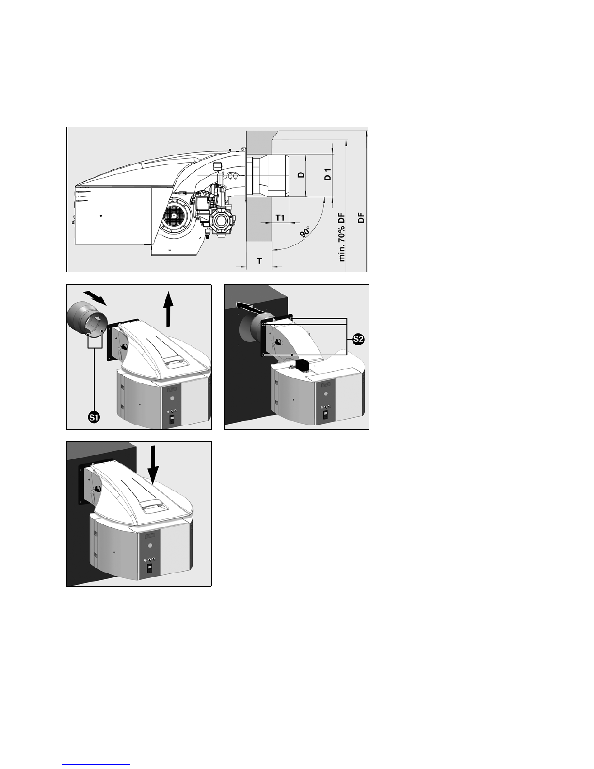
Burner assembly
• Remove cover.
• Take the flame tube (delivered in a
separate box).
• Fit it on the burner body.
• Tighten the 2 fixing screws S1.
• Fit the boiler seal to the burner.
• Raise the burner with the aid of
hoisting eyes 19 and fix it to the
boiler.*
• Tighten the 4 fastening screws S2
(comply with tightening torques).
• Place cover back on.
* Alternatively a forklift truck may be
used for fixing it if the burner is fixed
to the transport pallet supplied with it.
Provision must be made for adequate
transport safety. It may be necessary
to use suitable materials for transportation (lashing straps).
The burner boiler must be tested while in
operation to ensure it is leak-proof.
Every effort must be made to ensure that
exhaust gases cannot leak in harmful
amounts. Poorly sealed burner boiler
connections may result in combustion
problems
D = see dimensioned drawings
D1 = see dimensioned drawings
DF = combustion chamber diameter
T1 = 70 to 200 mm
T = standard muffle depth
(option : extensions: see technical
data)
Note for reverse flow boilers!
For reverse flow boilers, the dimension
T1 is only a recommended value.
Depending on type of boiler the burner
head must stand at least 70 mm ahead
the opening for exhaust gas turning
back.
Installation
Burner assembly
Page 8

09/2011 - Art. Nr. 4200 1040 7900A8
Installation
Burner head setting data GL-RZ3/LFL
Ø a Ø b Ø c d e f g
X
min max
N6.2400 320 270 240 29 121 60.5 380 148 137
N6.2900 320 270 240 29 121 60,5 380 148 137
N7.3600 320 270 240 40 150 60 425 202 182
N7.4500 340 270 240 30 150 60 425 195 130
Page 9

09/2011 - Art. Nr. 4200 1040 7900A 9
Installation
Gas train
Gas train description
Gas train installation
To install the gas train supplied in the
burner, the unions and seals intended
for this must be used (supplied with the
product).
Warning: in order to prevent injury, heavy
gas train components should only be fitted
using suitable aids and lifting equipment
(crane, cable slings, assembly supports).
The max. tightening torques must be
complied with (see chapter on Installation/
tightening torques). The unions must be
tightened crosswise and evenly. The union
must be checked to ensure that it is tight.
For further information, please refer to the
chapter on commissioning the gas connection.
Gas valve group selection
The gas trains must be dimensioned to suit
the throughput required and the available
gas pressure. The gas valve group is
defined on a system-specific basis.
The following must be taken into consideration:
• Burner output,
• Combustion chamber counterpressure,
• Gas pressure loss in the burner head,
• Gas pressure losses in the gas fittings.
The total drop in gas pressure must always
be lower than the available gas flow
pressure.
The burner's scope of delivery may include a
gas train. In this case, the burner and the gas
train are issued with a CE Declaration of Conformity. If the gas train is not delivered with
the burner, the conformity of the burner is
valid only if the gas fittings and the design of
the gas train satisfy the burner test specified
by EN 676 and meet the Pressure Equipment
Directive. Individual testing will be necessary
where this is not the case. The gas train
delivered has its own documentation
including operating instructions and a spare
parts list. There follows a general description
of the gas train.
Gas trains with a double gas valve are
intended for the supply, main shut-off, gas filtration, gas pressure regulation and monitoring of the gas supply. They are compatible for
use with gases conforming to the specifications of the gas fittings. The design complies
with EN 676. All function parts have been
individually tested and awarded the CE mark
and number of the notified body. The prefitted
gas train is subjected to a leak test at the
manufacturer's works.
Low- and high-pressure gas trains
If the outlet side of the regulator, i.e. individual
fittings and instruments downstream of the
gas pressure regulator, has not been
designed to be compatible with the maximum
supply pressure that occurs in the event of a
fault, the gas train must be equipped with a
safety shut-off valve (SSOV) and a safety
relief valve (SRV) in accordance with EN 676.
This equipment is generally required for
maximum supply pressures of >360 mbar
and > 500 mbar respectively. These are
known as high-pressure gas trains. If all
fittings and instruments of the gas train have
been designed/approved for the maximum
supply pressure that occurs in the event of a
fault, the gas train is known as a low-pressure
gas train. This is the case, depending on
component selection, for maximum supply
pressures of 360 and 500 mbar.
Page 10
09/2011 - Art. Nr. 4200 1040 7900A10
Installation
Gas train
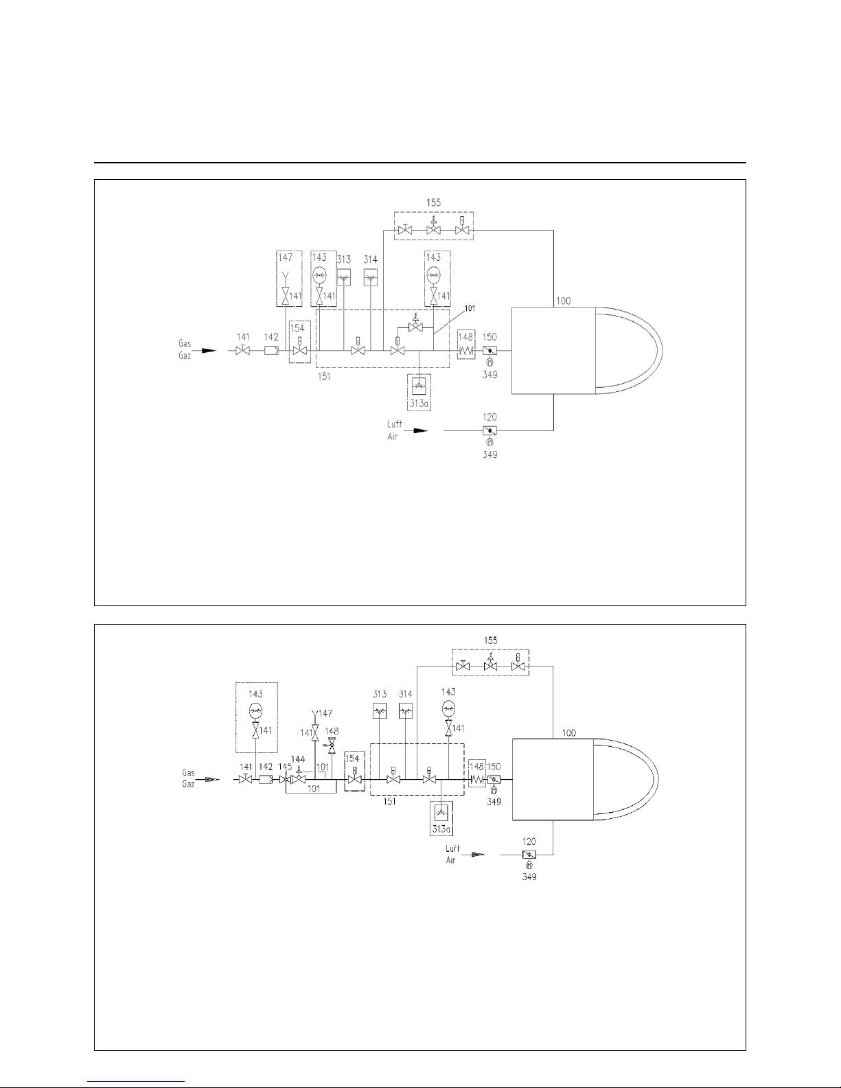
Basic design
100 Burner
101 Gas pressure impulse pipe
120 Air flap
141 Ball valve
142 Gas filter
144 Gas pressure regulator
145 Safety gate valve (SGV)
148 Safety relief valve (SRV)
150 Gas control butterfly
151 Double gas valve or 2 single valves
155 Ignition unit
313 Min. gas pressure switch
314 Gas pressure switch for checking valve tightness
349 Servomotor
Options in accordance with country-specific requirements:
143 Pressure gauge with pushbutton valve
147 Test burner with pushbutton valve
148 Compensator
154 Gas safety valve (additional)
313a Max. gas pressure switch
High pressure
100 Burner
101 Gas pressure impulse pipe
120 Air flap
141 Ball valve
142 Gas filter
150 Gas control butterfly
151 Double gas valve with integrated regulation
(Siemens VGD system shown)
155 Ignition unit
313 Min. gas pressure switch
314 Gas pressure switch for checking valve seals or valve
tightness control device
349 Servomotor
Options in accordance with country-specific requirements:
143 Pressure gauge with pushbutton valve
147 Test burner with pushbutton valve
148 Compensator
154 Gas safety valve (additional)
313a Max. gas pressure switch
Low pressure
Page 11

09/2011 - Art. Nr. 4200 1040 7900A 11
Description
The gas trains with Dungs MBC ...
double gas valves MBC... are used for
gas supply, as the main isolation valve,
for gas filtering, gas pressure regulation
and monitoring of the gas supply. They
can be used for all gases in the 1, 2, 3
gas families in accordance with DVGW
worksheet G 260/1 and/or EN 437. The
design complies with EN 676. All the
functional components have been
tested individually and awarded the CE
mark and number of the Notified Body.
The premounted gas valve group is
subjected to a leak test at the manufacturer's works.
Minimum scope of delivery for
gas trains
in accordance with
EN 676:
- 1 Ball valve
- 1 Gas filter
- 1 Double gas valve with spring 580 mbar
- 1 Min. gas pressure switch
- 1 Leakage controller or 1 gas pressure
switch for valve leak test
Options:
- Springs for other outlet pressures
- Test burner with pushbutton valve
- Pressure gauge with pushbutton valve
- Compensator
- Max. gas pressure switch
- Gas meter
- Pipe parts and connection parts
- Ignition gas device
- Installation support
- High-pressure regulator with safety
shut-off valve (SSOV)
- Settling section with pulse lines for
high-pressure regulator
- Safety relief valve (SRV)
- Additional gas safety valve
Low and high-pressure gas trains
If the outlet side of the regulator, i.e.
individual fittings and instruments downstream of the gas pressure regulator,
has not been designed to be compatible
with the maximum supply pressure that
occurs in the event of a fault, the gas
train must be equipped with a safety
shut-off valve (SSOV) and a safety relief
valve (SRV) in accordance with EN 676.
This equipment is generally required for
maximum supply pressures of
>360 mbar and > 500 mbar respectively. These are known as highpressure gas trains. If all gas train
fittings and equipment have been
designed and/or approved for the
maximum supply pressure that occurs in
the event of a fault, the gas train is
known as a low-pressure gas train. This
is the case, depending on component
selection, for maximum supply
pressures of 360 and 500 mbar.
Gas valve group
The gas valve group is defined on a
system-specific basis.
The following must be taken into consideration:
• Burner output
• Furnace counterpressure
• Gas pressure loss in the burner head
• Gas pressure losses in the gas fittings
The total drop in gas pressure must
always be lower than the available gas
flow pressure.
The section of the pipings must be calculated so that the loss of load doesn’t
exceed 5% of the supply pressure.
Warning!
With burners that have the CE mark,
only the use of gas fittings that have
been approved on the basis of burner
type-testing is permitted.
If alternative gas fittings are used, the
burner must undergo individual testing
by the relevant testing body.
Subject to change without notice due
to ongoing technical developments.
Gas train with MBC
Technical data:
Types of gas:
Gas types of gas families 1, 2 and 3
according to DVGW Worksheet
G 260/1
Max. inlet pressure:
MBC700-1200 with CG15 ignition gas
fittings: 360 mbar
without ignition gas fittings: 360 mbar
MBC1900-5000 with CG15 ignition
gas fittings: 360 mbar
MBC1900-5000 with FRS 505/ MVD
505 ignition gas fittings: 500 mbar
without ignition gas fittings: 500 mbar
Elect. connection: AC 220-240 V,
50 Hz
Protection level: IP 54
Ambient temperature:
-15 °C to +60 °C
Installation
Gas train
Description of gas train with MBC...
Page 12
09/2011 - Art. Nr. 4200 1040 7900A12
Technical data
Gas multiblock MBC-.../SE:
Type of gas:
Gases in accordance with DVGW
worksheet
G 260/1, gas families 1, 2, 3
Electrical data:
230 V -15% + 10%, other voltages on
request
50...60 Hz
Protection level: IP 54
Ambient temperature:
-15C to +60C
Installation position:
MBC-300-1200: magnet vertically
upright or magnet horizontal
MBC-1900-5000: magnet vertically
upright
Max. operating pressure:
MBC-300-1200: 360 mbar
MBC-1900-5000: 500 mbar
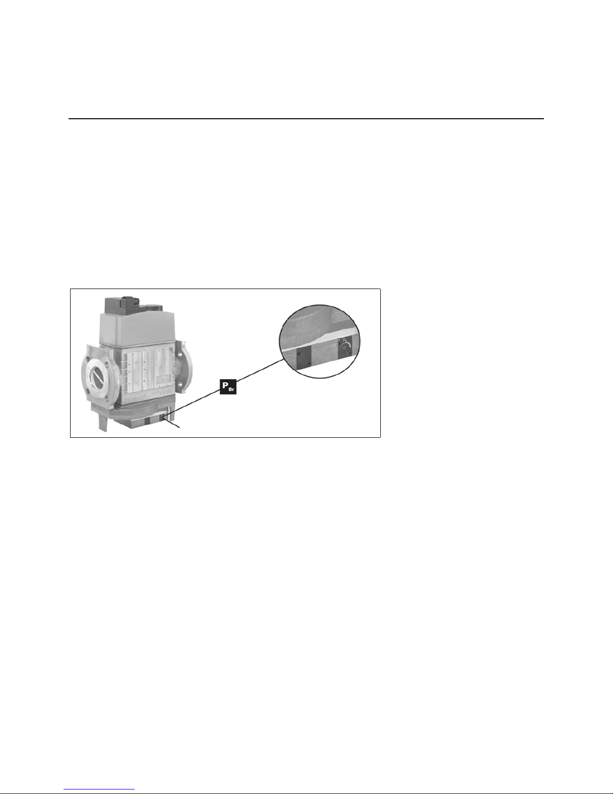
The MBC...SE gasmultibloc integrates
the filter, valves and servo pressure
regulator into one compact unit:
- Dirt trap: fine filter (MBC-300-1200
only)
- 2 solenoid valves up to 360 mbar in
accordance with DIN EN 161 Class A
Group 2 fast-closing, fast-opening
(MBC-300-1200)
- 2 solenoid valves up to 500 mbar in
accordance with DIN EN 161 Class A
Group 2 fast-closing, fast-opening
(MBC-300-1200)
- Servo-pressure regulation component
in accordance with DIN EN 88 Class A
Group 2, EN 12067-1
- Outlet pressure: 0 - 300 mbar (MBC300-1200), 4 - 300 mbar (MBC-1900-
5000)
- Sensitive adjustment of the outlet
pressure with the SE version for
optimum outlet pressure sensitivity
- Sensitive adjustment of the gas and
air pressure ratio with the VEF version
- Flanged connections with pipe
threads in accordance with ISO 7/1 or
NPT (MBC-300-1200)
- Flanged connections in accordance
with EN 1097-1 / ISO 7005 (MBC1900-5000)
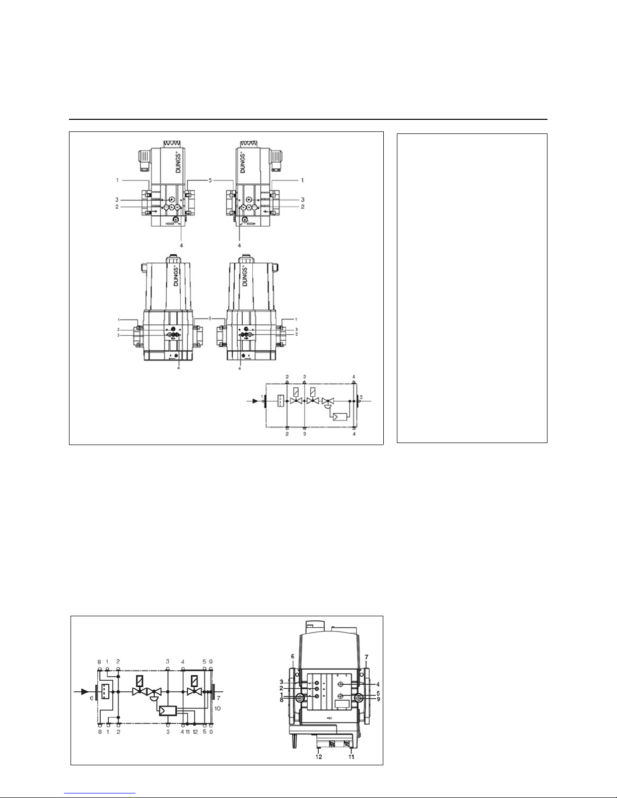
1, 2, 3
Seal plug G 1/8
4, 5, optional
Connection system accessories (optional)
6, 7
Seal plug G 1/4
8, 9, optional
Seal plug G 1/2 (optional)
10
Impulse line p
Br
(integrated)
11
Breather plug G 1/8
Installation
Gas train
Description of Dungs MBC double gas valve... (gas multiblock)
Pressure switches
MBC-300/
700...
MBC-1200...
1, 2, 3, 4, 5
Seal plug G 1/8
MBC-...-SE 1900-5100
Pressure switches
Page 13
09/2011 - Art. Nr. 4200 1040 7900A 13
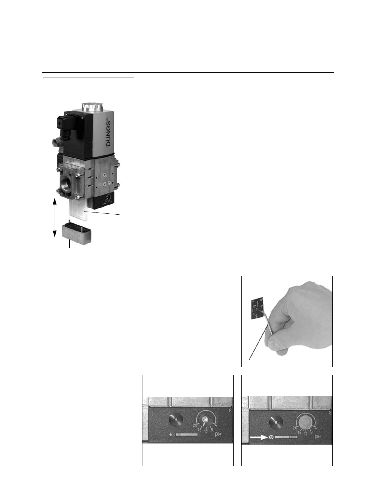
Filter inspection must be carried out
at least once a year
Replace filter if p between pressure
port 1 and 2 > 10 mbar.
Replace filter if p between pressure
port 1 and 2 is twice as high as the last
measurement.
1. Interrupt gas supply: close ball valve.
2. Unscrew screws 1-2.
3. Replace fine-filter element 3.
4. Screw in and gently tighten screws 1-
2.
5. Carry out a function test
and a test to check the water tightness
p
max.
= 360 mbar.
Space required for filter replacement:
MBC-300-...: 150 mm
MBC-700-...: 170 mm
MBC-1200-...: 230 mm
Adjusting the MBC-300-700-1200-SE
pressure regulating component
1. Open the slide.
2. Start the burner, correction of set
values possible while burner in
operation (fig. 1).
3. Check ignition safety of the burner.
4. If necessary repeat the setting steps.
Check intermediate values.
5. Apply a security seal to the adjusting
screw, see right.
Optimum combustion and ignition
safety must be ensured.
Security seal
After you have set the desired nominal
pressure value:
1. Close the slide.
2. Secure the slide in closed position
using the screw (fig. 3).
Installation
Gas train
Changing MBC-300-700-1200 filter
Setting the MBC-300-700-1200-SE pressure regulating component
3
1
2
1
Allen key no. 2.5
Open2Closed
3
Page 14
09/2011 - Art. Nr. 4200 1040 7900A14
Installation
Gas train
Setting the MBC-1900-5000-SE pressure regulating component
Allen key no. 2.5
Adjusting the MBC-1900-5000-SE
pressure regulating component
1. Open the protective caps.
2. Start the burner, correction of set
values possible while burner in
operation (see figure).
3. Check ignition safety of the burner.
4. If necessary repeat the setting steps.
Check intermediate values.
5. Apply a security seal to the adjusting
screw (see below).
Optimum combustion and ignition
safety must be ensured.
Page 15
09/2011 - Art. Nr. 4200 1040 7900A 15
Installation
Gas train
Description of double gas valves VGD... with servomotors SKP
VGD 20
VGD 40
SKP 15
SKP 25
SKP 75
Technical data
Double gas valves VGD with servomotors SKP:
Type of gas:
Gases in accordance with DVGW
worksheet
G 260/1, gas families 1, 2, 3 and
biogas (H
2
S-content 0.1 Vol.% max.),
H
2
Electrical data:
220 V -15%...240 V +10%
100 V -15%...110 V +10%
50 to 60 Hz
Protection level: IP 54
Media temperature :-15°C to +60°C
Ambient temp.: -10°C to +60°C
Installation position:
Magnet vertically upright or on its side,
magnet horizontal
Max. operating pressure:
VGD20: 500 mbar
VGD40: 700 mbar (DN 40 and DN 50
to 1000 mbar)
Double gas valve VGD with
servomotors SKP
The combined servomotor and valve
perform the following functions:
• safety shut-off valve Class A Group 2
in accordance with EN 161 (SKP15...)
• safety shut-off valve Class A Group 2
in accordance with EN 161 with gas
pressure regulator (SKP25...,
SKP55..., SKP75...)
The electrohydraulically operated servomotors with valve are designed for
gases of families I to III and air, and are
intended mainly for use in gas-fired
furnaces.
They are slow-opening and fast-closing.
The servomotor can be combined as
desired with any of the valves and
nominal widths specified above.
The servomotor can be supplied with a
limit switch (closed position signalling).
Valve dimension information is provided
on the "Throughput diagram" in the
relevant valve datasheet.
The SKP25... operates as a constantpressure regulator with setpoint spring.
It is mainly intended for use with forced
draught burners
- with mechanical coupler;
- with electronic coupler.
The SKP75... operates as a constantratio pressure regulator and regulates
gas pressure in proportion to the
pressure of the combustion air. This
keeps the gas/air ratio constant across
the entire load range. It is intended
mainly for use with modulating forced
draught gas burners with pneumatic
coupler.
System accessories available for the
double gas valve include the VPS 504
leak testing system and the GW...A5
pressure switch.
Page 16
09/2011 - Art. Nr. 4200 1040 7900A16
Installation
Gas train
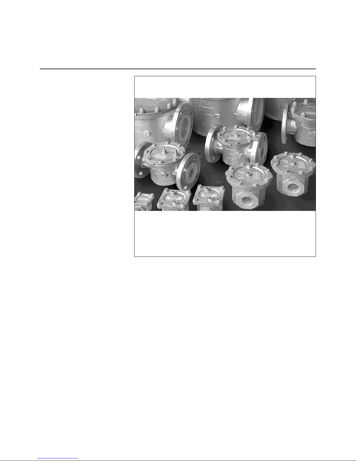
Gas filter
Installation and mounting of the gas
filter
The gas filter may be installed in any
desired position. Take care only to
observe the direction of flow of the gas
(arrow on filter housing). Make sure
there is adequate clearance to facilitate
the removal of the cover and replacement of the filter cartridge.
Filter replacement
The filter cartridge should be replaced
with a new one as soon as a high
pressure drop is noticed. If a new filter
cartridge is not at hand it will be possible
to wash the filter mat in 40°C water
adding some light-duty detergent. Allow
the mat to dry before reinstallation.
Warning: when installing the filter mat,
comply with the marking or adhesive
label.
Page 17
09/2011 - Art. Nr. 4200 1040 7900A 17
Installation
Gas train
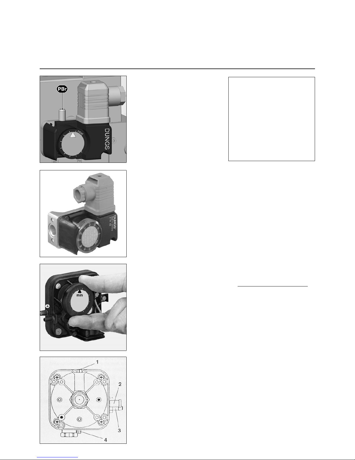
Gas/air pressure switch
Determining the differential preflushing pressure and adjusting the
differential pressure switch
• Burner in the pre-aeration phase.
• Measure pressure on test
connection (2).
• Measure vacuum on test
connection (3).
• Add the measured pressures.
• Set the scale to 90% of the calculated
value.
Switch function test
• Test buttons are provided to check the
switch functions for proper operation
(with safety cut-out and interlock). The
burner is normally run in part-load
condition when testing the safety functions. On pressing button (4) the
vacuum will be removed which causes
the differential pressure to drop below
the required level. If it is necessary to
test the pressure switch functions
under full-load conditions this may be
done by pressing button (1).
Technical data:
Type of gas:
Gases according to DVGW Worksheet
G 260/1, gas families 1, 2, 3
Protection level: IP 54
Ambient temp.: -15°C to +50°C
Installation position: any
Operating pressure up to:
GW 50/150 A5A6 500 mbar
GW 500/ A5/A6 600 mbar
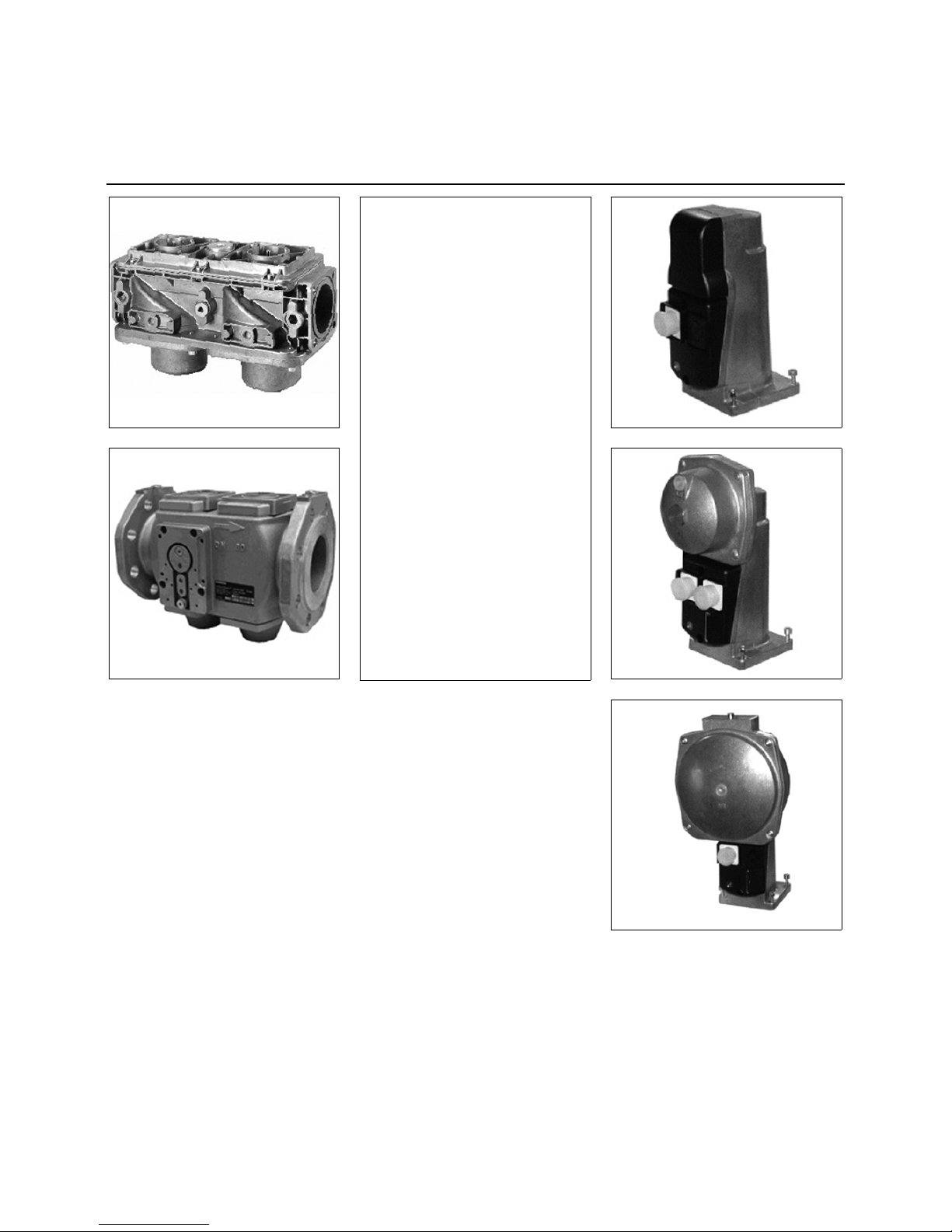
Gas pressure switch GW...A5/A6
The gas pressure switch is designed to
monitor the gas flow pressure. It can be
used for monitoring either falling
pressure (minimum) or rising pressure
(maximum, specified for equipment
according to TRD 604).
The types GW...A5/A6 may be used as
pressure switches of a specific construction according to VdTÜV leaflet
"Pressure 100/1" for application in
furnaces complying with TRD 604.
The setpoint (switching point) may be
selected by means of a setting disk with
vessel.
Air pressure switch
The air pressure switch is provided for
monitoring the pressure of the combustion
air fan.
Pressure switch LGW... is suitable for
switching an electrical circuit or for
switching it on or off if the actual pressure
values
are changing vis-a-vis the setpoint.
The pressure switch LGW... can be used
as overpressure, vacuum or differential
pressure switch for air and non-aggressive
gases but not for gases according to
DVGW Worksheet G 260/l.
Certification
The pressure switch has been tested in
accordance with EN1854 and is CE/DIN-
DVGW-registered. It has been registered
in other important gas consumption countries.
N.B.(Gas and air pressure switches)
The pressure switches must be set in
accordance with the specifications.
Furthermore, each time they are set, a
function test must be carried out. Noncompliance could result in personal
injury or damage to property!
Once the pressure switches have been
set, they must be protected to prevent
settings from being altered. For
example, this can be done by placing a
spot of varnish on at least one of the
screws on the equipment's protective
cover.
Setting the min. gas pressure switch
Remove the protective cover. At the
rated output, measure the gas flow
pressure and calculate the switch-off
pressure by reducing by approximately
20%. Adjust the graduated disc to the
desired switch-off pressure opposite the
arrow (the graduations are approximate
values). Operate the burner at minimum
power. Close the gas shut-off valve
slowly to obtain the desired switch-off
pressure. Turn the graduated disc until
the burner switches off. Refit and screw
down the protective cover.
Max. gas pressure switch
Remove the protective cover. At the
rated output, measure the gas flow
pressure and calculate the switch-off
pressure by increasing by approximately
20% (no more than 30% under any circumstances). Adjust the graduated disc
to the desired switch-off pressure
opposite the arrow (the graduations are
approximate values). Operate the
burner at minimum power. If the max.
gas pressure switch switches off the
burner, increase the adjustment value
but not to more than 130% of the flow
pressure at the rated output.
Gas pressure switch A5
Gas pressure switch A6
Page 18

09/2011 - Art. Nr. 4200 1040 7900A18
Gas train
Leakage controller
Test burner
1 Wieland 7P socket
3 Filter element
4 O-ring Ø10.5x2.25
5Fuse
T6.3 250V Ø 5x20
6 Yellow indicator On :
Leakage test OK
7 Red indicator On :
Leakage test NOK
Manual clear
8 Spare fuses
9 pa (p2) pressure switch Ø 9
pe + 20mbar
10 pe (p1) pressure switch Ø 9
inlet pressure (distribution)
Leakage controller VPS 504 S02
Working principle :
Prior to each burner start-up, the controller checks for possible leaks between
safety and main valves by increasing
supply pressure.
Electrically, the leakage controller is
serially connected between the thermostatic circuit and burner control and
safety unit.
Installation :
Directly on valve.
Program stages :
On stoppage, safety and main valves
are closed.
On thermostat stoppage, the leakage
controller is turned on and booster
increases supply pressure by 20 mbar.
After no more than 30 seconds
operation :
- the leakage test has been passed; the
yellow light comes on and current is
released to feed the burner’s control
and safety unit, which then starts its
program cycle.
- If the leakage test is not passed; the
red light comes on and the power
supply to the control and safety unit for
the burner is not released. Control
cycles have to be restarted manually.
Change valve if fault persists.
Setting :
The controller requires no on-site
setting.
Working test :
While controller is working :
• Open pa pressure switch. The precip-
itated leak prevents superpressure
from building up and safety unit locks.
• Reclose pa pressure switch.
• Release controller safety by pressing
red indicator light.
The leakage test is restarted; after 30
seconds, yellow indicator lights up and
powers up the burner's control and
safety unit, which then starts its program
cycle.
Test burner
Depending on the country-specific
requirements, when installing steam
boilers it may be necessary to fit a test
burner to the gas train (e.g. in line with
directive TRD 412). This is used to vent
the gas pipes.
The gas supply is switched on by
pressing the button (1). The flow of gas
brings in the required amount of combustion air via the hole in the burner tube
(3). The gas/air mixture is routed
towards the burner head (4) and ignited
manually at its opening. Gas is supplied
for as long as the button is pressed and
cut off when it is released.
Technical data:
• Type of gas:
gases in accordance with DVGW
worksheet G 260/1, gas families 1, 2, 3
• Ambient temp.: -15°C to +70°C
• Installation position: vertical, facing
upwards
• Operating pressure to: 500 mbar
Page 19

09/2011 - Art. Nr. 4200 1040 7900A 19
Installation
Hydraulics
General information regarding fuel oil system
Fuel oil hydraulics diagram
100 Burner
101 Fan
118 Nozzle
120 Air flap
143 Pressure gauge (optional)
175 Filter
176 Pump
178 Solenoid valve, supply line
349 Servomotor
Page 20

09/2011 - Art. Nr. 4200 1040 7900A20
Installation
Hydraulics
Fuel oil pressure switch
Fuel oil pressure switch
Fuel oil pressure switches are used to
monitor burners to ensure that they do
not exceed or fall below specific fuel oil
pressures.
Depending on the burner variant,
pressure switches may be specified for
backflow only
or for backflow and the supply line. The
shut-off pressure in question is set
depending on the system parameters
(ring line pressure, fuel oil nozzle etc.).
Fuel oil pressure damping
To reduce fluctuations in fuel oil
pressure, a throttle screw (2) or a
capillary tube may be screwed into the
connection nozzle.
Adjustment of switching pressure
To adjust the switching pressure, the
adjustment button (1) can be pulled
upward and reinserted the opposite way
around.
Setting the fuel oil pressure switch
min.:
The shut-off pressure is the fuel oil
supply pressure at full load, minus
approx. 20%.
Setting the fuel oil pressure switch
max. (only for burners with a return
nozzle):
The shut-off pressure is the ring line
pressure with a full load plus approx.
2...3 bar.
The set shut-off pressure should also
take cognisance of the set switch difference.
When the setting procedure is complete,
the setting button must be returned to its
original orientation
for safety.
A seal must be applied to the pressure
switch to secure the setting (Item 4).
Switching difference
The switching difference may be set at
the limits of the pressure switch in
accordance with the values in the table.
To do this, the set screw must be rotated
in the adjusting screw (3) for the
switching point. 1 turn modifies the
switching difference by approx. 20% of
the total switching difference range.
Model Adjustment
range
Switching
difference
Application
DSB 158 F ... 0-25 bar 1.0... 7.5 bar
Standard EN 267 supply line
and backflow
Page 21

09/2011 - Art. Nr. 4200 1040 7900A 21
Installation
Hydraulics
General information regarding fuel oil system
Fuel oil connection
Hoses are used to make a connection to
the fuel oil tubes or the gate valves. To
prevent kinks and therefore any risk of
rupture, the hoses must be fed correctly
(no tension or distortion). When installing the fuel oil tubes or the gate valves,
care must be taken to ensure that the
lines terminate as close to the burner as
possible and that they are positioned in
such a way that the boiler door and the
burner can be swivelled out without
obstruction.
Gate valve
In the fuel supply feed line, manual gate
valves must be fitted before the burner
(supply line and backflow). These must
be installed in such a way that they are
easily accessible. The manual gate
valves are not included in the scope of
delivery.
Gas and air separators
Air or gas In the fuel supply line could
cause noise and operational problems.
In order to avoid this, a suitable gas air
separator must be fitted in the fuel
supply line.
Fuel oil filter
To protect the oil pressure pump and the
hydraulic system, a filter must be
installed before the pump.
A filter with ≤ 200 µm is recommended.
Installation options
• Two-line installation (separate supply
line and return line with no delivery
pump)
• Ring line system (with delivery pump
and gas-air separator)
Fuel oil pressure regulator (supply
line)
The supply pressure is regulated by the
pressure regulator fitted in the pump
and, depending on the burner output
and make of nozzle, it is set to 1015 bar. The pressure regulator is
actuated by rotating screw 3.
Before commissioning, the pump must
be filled with fuel oil.
Venting
With the ring line, if any, in operation,
open the supply line and return gate
valves. Reduce the oil pressure on the
pressure regulation valve. Switch on the
pump by depressing the contactor.
Check whether the direction of rotation
is correct, the pump is supplying fuel oil
and the fuel oil hydraulics system is
leak-proof. Vent the pump, e.g. at the
pressure gauge connector. When commissioning the burner, the oil pressure
must be increased slowly until it reaches
the operating value.
Pressure regulation (fuel oil intake
pressure)
The maximum possible vacuum is
0.2 bar. If the vacuum pressure is
greater than this, gas emissions are
produced from the fuel oil and this could
cause problems.
In the case of ring line operation, the oil
pressure at the pump must not exceed
the maximum permissible pressure. For
the maximum pressure, please refer to
the technical data.
Connecting test devices
Before setting the burner, test pressure
gauges must be fitted to determine
supply pressure 1 and possibly intake
pressure 2.
N.B.:
When commissioning is complete, the
pressure gauges must be removed and
the connections must be duly sealed.
If the pressure gauges are left on the
burner, they must all be shut off with
shut-off valves.
Oil hoses for burner connection
Burner type DN Length [mm] Connection on
both sides
Minimum bending radii R
[mm]
N6.2400 20 1500 R 1/2" 145
N6.2900 20 1500 R 1/2" 145
N7.3600 20 1500 R 3/4" 145
N7.4500 20 1500 R 3/4" 145
Connection to the test point
Burner Test point for
intake
pressure
Test point for
pump pressure
(at pump)
Test point for pump pressure (bef. 1st safety valve)
N6.2400 G1/2 G1/4 Ø10 pipe connector acc. to DIN EN ISO 8434-1*
N6.2900 G1/2 G1/4 Ø10 pipe connector acc. to DIN EN ISO 8434-1*
N7.3600 G1/4 G1/4 Ø10 pipe connector acc. to DIN EN ISO 8434-1*
N7.4500 G1/4c G1/4 Ø10 pipe connector acc. to DIN EN ISO 8434-1*
*In order to be able to use the test components, a cutting ring in acc. with DIN EN ISO 8434-1 is
required.
If the pressure gauge is not left on the burner, a union nut in acc. with DIN EN ISO 8434-1 is also
required.
N6
N7
Page 22

09/2011 - Art. Nr. 4200 1040 7900A22
Installation
Hydraulics
Pump type J7
Areas of application
- Light, medium-grade oil
- Two-line system.
- Generally connected to the solenoid
valve in the nozzle line
Description of Functions
The gearbox draws the fuel oil from the
tank through the built-in filter and
supplies it under pressure to the valve
which controls the oil pressure for the
nozzle line.
In the case of two-line installations, fuel
oil which exceeds the nozzle capacity
flows back to the tank through the valve
via the return opening.
Description of how the integrated valve
works: a flat section on the pressure regulation piston assists drainage of the fuel
oil*. If rotation of the gearbox is
increased when pumping commences,
all the fuel oil flows to the backflow via
the flat section and the hydraulic valve
remains closed. It is only when a specific
rotational gearbox speed is reached that
the fuel oil can no longer be returned via
the flat section. The pressure before the
control piston increases rapidly and
opens the valve as soon as it is higher
than the force of the valve springs.
When switched off, the valve closes as
soon as the gearbox capacity is lower
than the outflow via the flat section on
the piston on account of the lower rotational speed.
Opening and closing of the valve
depends on the size of the gearbox and
the set pump pressure.
Venting
In the two-line system, venting is carried
out automatically. However, venting can
be speeded up by opening the pressure
connection.
*In the J 1002 models, the bypass hole
in the nozzle plug prevents shut-off. For
shut-off, a separate solenoid valve must
be installed in the nozzle line.
Pumping capacity
Pump power requirements
Capacity (l/hr)
Power (W)
Pressure (bar)
Pressure (bar)
Viscosity = 5 cSt - pump speed = 2850 rpm
Allowance has already been made for gearbox wear in the
curves shown. In selecting the gearbox capacity, you
should therefore ensure that the pump is not over-dimensioned.
Viscosity = 5 cSt - pump speed = 2850 rpm
Page 23

09/2011 - Art. Nr. 4200 1040 7900A 23
Installation
Hydraulics
Pump type J7
General
Attachment Flange attachment as per EN 225.
Model 1000 Model 1001/1002
Connections Conical Cylindrical in acc. with ISO 228/1
Supply line and backflow 1/4" NPTF G 1/2
Nozzle outlet 1/8" NPTF G 1/4
Pressure test connection 1/8" NPSF G 1/8
Vacuum test connection 1/4" NPTF G 1/2
Valve function Pressure regulation and shut-off (apart from J 1002).
Filter Filter area: 45 cm²
Mesh size: 170 µm
Shaft Ø 11 mm in acc. with EN 225.
Bypass-plug Installed in the return opening
For two-line installaiton
Weight 4 kg
Hydraulic data
Pressure range C : 10 - 21 bar
E : 10 - 30 bar
Pressure setting
when delivered
12 bar
Viscosity range 2 - 75 mm²/s (cSt)
Fuel oil temperature 0 - 90°C in the pump
Supply pressure 1.5 bar max.
Return pressure 1.5 bar max.
Intake height 0.45 bar max. vacuum in order to avoid air separation
Rotational speed 3600 rpm max.
Torque (at 45 rpm) 0.30 Nm
Fuel oil under vacuum
Fuel oil under
pressure
Excess fuel oil
returned to the tank
or to the section side
Supply
Vacuum test
connection
Gearbox
Pressure
regulation
To the nozzle
Bypass
plug
screwed down
firmly
Pressure test
connection
Backflow
TWO-LINE
INSTALLATION
Page 24

09/2011 - Art. Nr. 4200 1040 7900A24
Installation
Hydraulics
Pump type TA3
Areas of application
- Domestic oil and heavy-grade oil (for
use with kerosene, please contact
SUNTEC)
- Two-line system.
Description of Functions
The gearbox draws the fuel oil from the
tank and supplies it under pressure to
the valve which controls the oil pressure
for the nozzle line.
In the case of two-line installations, fuel
oil which exceeds the nozzle capacity
flows back to the tank through the valve
via the return opening.
Venting
Pump venting is speeded up by opening
a pressure connection.
Note:
All TA pumps supplied are for two-line
installation (bypass plug screwed into
the vacuum connection).
To convert to single-line operation, the
bypass plug must be removed and the
return opening must be sealed off with a
gasket and metal plug.
Pumping capacity
Pump power requirements
Capacity (l/hr)
Power (W)
Pressure (bar)
Pressure (bar)
The values specified in the curves apply to new pumps
(with no evidence of wear)
The values specified in the curves apply to new pumps
(with no evidence of wear)
Viscosity
Viscosity
- Rotational pump speed = 2850 rpm
- Rotational pump speed = 2850 rpm
Page 25

09/2011 - Art. Nr. 4200 1040 7900A 25
Installation
Hydraulics
Pump type TA3
General
Attachment Flange attachment
Connections Cylindrical in acc. with ISO 228/1
Supply line and backflow G 1/2
Nozzle outlet G 1/2
Pressure test connection G 1/4
Vacuum test connection G 1/4
Shaft Ø 12 mm
Bypass-plug Used in the vacuum connection
for two-line installaiton
Weight 45.4 kg (TA2) - 5.7 kg (TA3)
6 kg (TA4) - 6.4 kg (TA5)
Hydraulic data
Pressure range 30 : 7 - 30 bar
40 : 7 - 40 bar
Pressure setting
when delivered
30 bar
Viscosity range 3 - 75 mm²/s (cSt)
(Fuel oil with a higher viscosity may be used if the fuel oil is supplied under pressure and is heated in such a way
that the viscosity falls below 75 cSt. For use with kerosene, please contact SUNTEC)
Fuel oil temperature 0 - 150°C in the pump
Supply pressure Light oil operation: vacuum 0.45 bar max.
in order to avoid air separation
Heavy-grade oil operation: 5 bar max.
Return pressure Light oil operation : 5 bar max.
Heavy-grade oil operation: 5 bar max.
Rotational speed 3600 rpm max.
Torque (at 40 rpm) 0.30 Nm
Selecting the heating element
Heating cartridge Ø 12 mm
Thread connection In acc. with EN 50262
Power 80-100 W
Fuel oil under vacuum
Fuel oil under pressure
Excess fuel oil
returned to the tank
or to the section side
Supply
Pressure
control
To the nozzle
Bypass
plug
screwed down
firmly
Backflow
TWO-LINE
INSTALLATION
Vacuum or
boost pressure
test connection
Pressure test
connection
Page 26

09/2011 - Art. Nr. 4200 1040 7900A26
Installation
Hydraulics
Nozzle line, 3-stage
3-stage nozzle line
The nozzle line consists of three pipes
each of which carries the fuel oil to a
nozzle. The flow of the fuel oil is controlled by the upstream fuel oil safety
valves. These are normally closed. Each
of the three valves controls a nozzle in
the fuel line. When the valves are
engaged, load stages 1, 2 and 3 are
implemented. In load stage 3, i.e. at
maximum burner output, all the valves
are open and all the nozzles are
operating simultaneously. To the front of
the nozzle line there is a nozzle plate
designed to hold the nozzles.
The table (see below) lists the standard
fuel oil nozzles for the lowest and
highest output range. Intermediate gradations are possible. The nozzle configuration selected must ensure that the
burner output falls within the specified
working field (see technical data). It
must not fall below or exceed this.
It is essential to have stable, hygienic
and reliable combustion. The fuel oil
pressure set must be taken into account
when selecting the nozzle.
Valve block
The valve block collects the oil and distributes it to the three fuel oil valves fitted
directly onto the block.
The fuel oil is supplied through the fuel
oil pump on the burner. Before it reaches
the fuel oil block, the fuel oil first passes
through the first fuel oil safety valve. The
valve block is fixed to the rear of the
nozzle line with two screws. In this way,
the entire burner head can be dismounted along with the nozzle line and
valve block.
The connections to be unscrewed
have been kept to a minimum.
The nozzles for the 3-stage nozzle line
are selected so as to meet the maximum
performance requirements of the boiler
with the best possible control range and
high combustion quality overall.
This means that in selecting the nozzles,
not only is the nominal capacity of the
relevant boiler crucial, so is the minimum
performance and the quality of combustion during each load stage.
The nozzle for the first stage must be
selected in such a way that it is within the
range of the permissible working field of
the burner. For the working field and the
minimum permissible outputs, please
refer to the technical data.
All the Monarch and Steinen nozzles
have permanent labels containing the
following information (subject to change
and based on CEN standards):
- Flow (in USGPH at 100 Psi = 6,895
bar)
- Manufacturer's code
- Spray angle
- Nozzle series ID
- Manufacturer's logo
Standard configuration for fuel oil nozzles for domestic fuel oil
Burner 1st stage 2
nd
stage 3rd stage
Model Size Model Size Model Size Fuel oil
pressure
supply line
[basic load]
N6.2400 min. Steinen SS60° 15.0 GPH Monarch PLP 60° 15.5 GPH Monarch PLP 60° 19.5 GPH 11.5 bar
N6.2400 max. Steinen SS60° 18.0 GPH Monarch PLP 60° 21.5 GPH Monarch PLP 60° 24.0 GPH 11 bar
N6.2900 min. Steinen SS60° 18.0 GPH Monarch PLP 60° 19.5 GPH Monarch PLP 60° 21.5 GPH 10 bar
N6.2900 max. Steinen SS60° 18.0 GPH Monarch PLP 60° 19.5 GPH Monarch PLP 60° 24.0 GPH 12 bar
N7.3600 min. Steinen SS60° 22 GPH Monarch PLP 60° 30 GPH Monarch PLP 60° 30 GPH 12 bar
N7.3600 max. Steinen SS60° 24 GPH Monarch PLP 60° 30 GPH Monarch PLP 60° 30 GPH 13.5 bar
N7.4500 min. Steinen SS60° 22 GPH Monarch PLP 60° 30 GPH Monarch PLP 60° 30 GPH 14 bar
N7.4500 max. Steinen SS60° 26 GPH Monarch PLP 60° 35 GPH Monarch PLP 60° 40 GPH 16 bar
Page 27

09/2011 - Art. Nr. 4200 1040 7900A 27
Installation
Hydraulics
Nozzle line, 3-stage
Oil throughput with pump pressure in bar
STEINEN
Oil through-
put at 7 bar
Kg/hr
Pressure in bar
GPH1012141820
10.00 38.28 41.93 45.29 51.36 54.14
11.00 42.11 46.13 49.82 56.50 59.56
12.00 45.94 50.32 54.36 61.64 64.98
13.00 49.77 54.52 58.89 66.77 70.40
14.00 53.6 58.71 63.42 71.91 75.81
15.00 57.43 62.91 67.95 77.05 81.23
16.00 61.26 67.10 72.48 82.19 86.65
17.00 65.08 71.29 77.00 87.31 92.05
18.00 68.91 75.48 81.53 92.45 97.47
20.00 76.57 83.87 90.60 102.7 108.3
22.00 84.23 92.27 99.66 113 119.14
24.00 91.88 100.7 108.7 123.27 129.96
26.00 99.54 109.04 117.8 133.5 140.8
28.00 107.2 117.4 126.8 143.8 151.6
Fuel oil, standard: 3.4 cst viscosity, .84 voluminal mass @ 20° C EN 293
Nozzle size Flow in l/hr at a pressure of (bar):
MONARCH
7 8.8 10.4 12.2 14
10.5 39.7 44.3 48.8 52.6 56.4
12 45.2 50.7 55.6 60.2 64.3
13.5 51.1 57 62.6 67.8 72.5
15.5 58.66 65.6 71.7 77.8 82.8
17.5 66.2 74.2 81 87.8 93.9
19.5 73.9 82.5 90.5 97.6 104.5
21.5 81.4 90.9 99.9 107.5 115
24 90.9 101.4 111.3 120.4 128.7
28 106 118.5 129.8 140 149.9
30 113.5 127.2 139.3 150.3 160.9
35 132.5 148 162.4 175.2 187.4
40 151.4 169.2 185.5 200.6 213.8
45 170.3 191 209 225.2 241.1
50 189.2 211.6 232 250.2 267.6
55 208.2 232.8 255.1 275.2 294.1
Page 28

09/2011 - Art. Nr. 4200 1040 7900A28
Commissioning
Control and safety unit LFL 1.../LGK...
LFL 1.../LGK... is designed for controlling and monitoring burners that operate
on the basis of a stepped or modulating
principle.
The following control and safety units
are installed as standard:
• Hot water applications - LFL 1.333
series 02
• Steam and hot water applications LGK 16.333A27
The safety times for these control and
safety units are listed in the table below.
Before commissioning, a check must be
carried out to determine whether the
safety times comply with national and
regional regulations. Other control and
safety unit variants can be obtained on
request.
N.B.
Do not press the reset button for
more than 10 sec!
R Reset button
R = Temperature or pressure
controller
M = Fan motor
Z = Ignition transformer
BV= Fuel valve(s)
LR= Load regulator
LK= Air flap
RV= continually adjustable fuel valve
or load stage valve
FS= Signal of flame
A = Starting type interval
A-B= Flame development interval
B = Burner has reached operating
position
B-C= Burner operation (heat genera-
tion)
C-D= regular shut-off
Functional diagramLFL 1.../LGK... Safety times
(sec)
t1 Pre-ventilating time 31,5
t3 Pre-ignition time 6
t4 Fuel valve enable 11.5
t5 output regulation release LR 11.5
t6 Post-ventilation time 17
t7 Interval between start command and voltage on terminal 7 3
t11 "OPEN" run time of air flap any
t12 "CLOSE" run time of air flap any
t13 Permissible post-combustion time 17
TSA Start-up safety time 3
Page 29

09/2011 - Art. Nr. 4200 1040 7900A 29
Commissioning
Electrical servomotor
Field of application
The SQM5... series servomotors are
designed for driving gas and air flaps in
medium to high output fuel oil and gas
burners. It is primarily designed for use
in the regulation of gas and combustion
airflow depending on the load.
• In conjunction with regulation with 3point or continuous (e.g. 4 ... 20 mA)
control signals or by the control and
safety units directly.
Technical documentation
SQM5... L&G 7815 D
Limit switches
The limit switches are actuated by
control cams which are set to a basic
position in the factory.
Disengaging mechanism
The drive shaft and camshaft can be disengaged separately.
A = Disengaging of drive shaft
N = Disengaging of camshaft
Warning!
The drive shaft and camshaft must not
be disengaged at the same time.
Page 30

09/2011 - Art. Nr. 4200 1040 7900A30
Commissioning
Electrical servomotor
Technical data SQM servomotor
Voltage 230 V -15%
50 / 60 Hz
240 V +10%
50 / 60 Hz
Power input 20 VA
Max. contact load 250 V 7.5 (3) A
Installation position as required
Ambient temperature- 20°C + 60°C
Protection level IP 54
Weight 3.3 kg
SQM 50.381A2
Duration with
130° rotation angle
22 sec
Torque 10 Nm
Description
The "SQM" servomotor is designed
for use in fuel oil, gas or two-stage
burners that operate in accordance with
the sliding or modulating principle. The
reversible servomotor comes with a synchronous motor which drives a shaft via
a gearbox. The shaft end carries a
coupling to drive the fuel and combustion air actuator.
The SQM servomotor has been
designed for dual-wire control by controller or switching units with changeover contacts.
Suitable potentiometers can be fitted for
a very wide range of applications.
The 60 Hz frequency will reduce the
running times by approx. 17 %.
Limit switch factory setting
The limit and auxiliary switches are set
by means of manually adjustable
latching cam plates. Scales are fitted
between the disks to facilitate the
selection of the switching points.
The cam plates are provided with a
small pointer for indicating the switching
point of a scale between the setting
ranges.
An additional scale fitted to the end of
the cam roller serves to indicate the
position of the servomotor.
The drive unit may be disengaged from
the controlling element by changing over
a rocker arm mounted to the gearbox.
This will allow any desired position of the
controller plate to be selected by hand.
Drive and output will be coupled in the
vertical position of the rocker arm.
The fuel-air curve must be set over the
entire adjustment range of the cam disk
so that safe operation can still be guaranteed even if the limit switch is overridden.
SQM servomotor, standard configuration of limit switch
Limit switch Function Standard setting [°]
1
Full load setting, gas,
Pre-ventilation setting gas/fuel oil
120
2
Basic load, gas,
Zero setting if burner is shut down, gas/fuel
oil
18
3 Ignition position, gas 20*
4
Air flap position, stage 1. Fuel oil
release stage 1, fuel oil
45
5 Fuel release stage 2, fuel oil 60
6 Air flap position, stage 2. Fuel oil 78
7 Fuel release, stage 3, fuel oil 90
8 Air flap position, stage 3. Fuel oil 120
9 Vessel, red part for anti-clockwise, black part for clockwise
P Potentiometer kit for further control functions (optional)
* The angle of limit switch 3 must be set a little higher than that of limit switch 2
Page 31

09/2011 - Art. Nr. 4200 1040 7900A 31
Commissioning
Flame monitor
Probe current measurement
Using a UV probe for flame monitoring
For the monitoring method, the UV
radiation from hot flame gases is used to
create the flame signal. A radiation
detector is a UV-sensitive tube with two
electrodes to which voltage is constantly
applied. When illuminated with light from
the 190...270 nm range of the spectrum,
it fires and applies current to the flame
signal amplifier. The UV tube does not
react to the after-glow of fireclay in the
furnace, sunlight, daylight or the lighting
used to illuminate the boiler room. The
tubes have a service life of approx.
10,000 hours at ambient temperatures
of up to 50°C; higher ambient temperatures reduce the service life considerably.
Burners used for constant or intermittent
operation for more than 24 hours without
a break (e.g. boiler sequence control) or
burners used in conjunction with steam
boilers must be fitted with control and
safety unit LGK 16... and the self-monitoring flame monitoring circuit (QRA
5...).
UV current measurement with QRA 5
In order to carry out accurate UV current
measurement, we recommend the use
of test device KF 8832. For UV current
measurements with normal test
equipment (microammeter) we
recommend that the measurement be
carried out as shown in the diagram. A
suitable capacitor must be integrated
into the test circuit (for details see the
table entitled "Probe currents and test
devices").
Connect the test device between the
control and safety unit and the UV flame
probe QRA 5... (terminals 22 (-) and 5
(+)).
Flame probe current test device KF8832
must not be left in constant use because
self-monitoring is not guaranteed during
the test process.
Ensure that the polarity is correct!
Flame probe current test device
KF8832 must not be left in constant
use because self-monitoring is not
guaranteed during the test process.
Alignment of UV probe QRA 5...
The movable connecting flange on the
probe tube facilitates precise alignment
of the probe window with the direction of
incidence of UV radiation.
Please note!
The terminal (22) must always be
earthed.
Cleaning the probe
The UV probe window must be regularly
inspected for dirt and cleaned. The
probe window must be kept free of dust.
If this measure proves unsuccessful, the
tubes must be replaced.
Test circuit for probe
current measurement
QRA2…, QRA10…,
QRA5… series D and
QRA5… series G
QRA2.
QRA5.
QRA2.
QRA5.
Page 32

09/2011 - Art. Nr. 4200 1040 7900A32
Commissioning
Flame monitor
Probe current measurement
Probe currents and test equipment
Min. required or max. achievable probe current in µA (DC)
QRA2 Ionisation
QRA5x.C...
QRA5x.E…
QRA5x.D...
QRA5x.G…
Automatic control unit min max min max min max min max
LFL1… 70 700 6 200 - - - -
LGK16… - - 12 100 35 50 120 270
Test
equipment
Recommended Tester KF 8832
Alternative
M1 - microammeter Ri max. 5000 Ω;
0 - 1000 µA
C - electrolyte capacitor 100...470 µF;
DC 10...25 V
-
M1 - microammeter Ri max.
5000 Ω; 0 - 1000 µA
C - electrolyte capacitor 470 µF; DC 25
V
Page 33

09/2011 - Art. Nr. 4200 1040 7900A 33
Commissioning
Gas train connection
Electrical connection
Checks before commissioning
Checks before commissioning
The following must be checked before
initial commissioning:
• That the burner is assembled in
accordance with the instructions given
here.
• That the burner is pre-set in accordance with the values in the adjustment
table.
• Setting the combustion components.
• The heat generator must be ready for
operation, and the operating regulations for the heat generator must be
observed.
• All electrical connections must be
correct.
• The heat generator and heating
system must be filled with water and
the circulating pumps must be in operation.
• The temperature regulator, pressure
regulator, low water detectors and any
other safety or limiting devices that
might be fitted must be connected and
operational.
• The exhaust gas duct must be unobstructed and the secondary air
system, if available, must be operational.
• An adequate supply of fresh air must
be guaranteed.
• The heat request must be available.
• Sufficient gas pressure must be available.
• The fuel supply lines must be
assembled correctly, checked for
leaks and bled.
• A standard-compliant measuring point
must be available, the exhaust gas
duct up to the measuring point must
be free of leaks to prevent anomalies
in the measurement results.
All electrical installation and connection work must only be carried out by
a suitably qualified electrician.
The applicable guidelines and direc-
tives must be observed, as
well as the electrical circuit
diagram supplied with the
burner!
Before connecting the burner,
it is essential to ensure that the entire
burner has reached the ambient temperature. Otherwise, there is a risk
that condensation will form on electronic components resulting in
damage to property and personal
injury!
Gas train connection
The connectors on the burner must be
used for connecting the gas train. Cognisance must be taken of the equipment
labelling and the electrical circuit
diagram.
Electrical connection
The electrical connections, i.e. the
installation materials and all the connectors and earth/ground connections, must
be installed in compliance with the specifications.
The electrical installation of the burner
must be carried out in accordance with
the circuit diagram drawn up for the
furnace.
The electrical connection of the burner
may only be performed by authorised
professionals.
Please note:
When installing the connection cable,
the cable loops selected must be large
enough to allow the boiler door to swivel
open.
When electrical connection work is
complete, the wiring for the burner
electrics must be checked.
This includes checking the direction of
rotation of the fan or the fuel oil pump
motor.
Page 34

09/2011 - Art. Nr. 4200 1040 7900A34
Commissioning
Gas connection
Gas connection
The gas lines and valve groups should
be installed and taken into operation in
accordance with the applicable engineering standards and regulations.
The connection between the gas distribution network and the gas ramp must
be done by authorised persons.
All the gas ramp components must be
fitted and installed without bending or
distortion or any other form of mechanical stress.
The section of the pipings must be calculated so that the loss of load doesn’t
exceed 5% of the supply pressure.
A quarter turn manual valve (not
supplied) must be provided for
upstream of the gas ramp and the filter.
The max. operating pressure for the
shut-off device must be 1.5 times the
max. connection pressure. Ease of
access must be guaranteed. Precautions must be taken to prevent unintentional actuation. The operating position
of the gate valve must be quite obvious.
The manually operated valve should
have fixed stops in the "OPEN" and
"SHUT" positions.
The filter must be installed on a horizontal nozzle with the cover in the vertical
position to enable cleaning.
Depending on the current specification,
a thermally triggered gate valve must be
provided for on site (not supplied).
All the gas ramp components must be
protected against condensation and if
necessary, a condensate trap (not
supplied) must be provided for on site.
The threaded unions used must be in
conformity with present standards
(tapered male thread, straight female
thread with sealing provided in the
thread).
Sufficient space must be provided for
setting and maintaining the gas ramp
components (gas pressure switch,
valves, pressure regulator, gas filter,
test burner etc.) (see technical data).
Gas properties
Prior to any installation work make sure
to obtain the following data from the gas
supply company:
1. Type of gas
2. Calorific value Hu
n
= kWh/m3 (kJ/m3)
3. Max. CO
2
content of exhaust gas
4. Gas connection pressure and rest
pressure
Type of gas test
Prior to mounting the burner to the gas
feed line check the available type of gas
and burner type against the data given
on the burner nameplate (attached to
burner).
Be sure the description of the burner
and the type of gas are the same as
indicated on the nameplate.
Gas connection pressure
A minimum connection pressure must
be available upstream of the burner gas
valve to ensure the proper functioning of
the burner.
For the installation of the valves and
instruments group take care to observe
the mounting instructions supplied by
their manufacturers (these are packed
with the equipment). The gas line
installed to the burner must be dimensioned in accordance with the throughput rate and the available pressure.
For selecting the nominal bore "DN" of
the gas valve group care should be
taken to observe the flue resistance
of the boiler and the gas pressure
loss of the burner and valve group.
Warning!
The absence of impurities and foreign
bodies must be checked before installation and commissioning of the gas ramp,
the lever valves and unions.
Gas valve group
The gas valve group can be connected
directly to the gas feed line. Take care
to observe the correct order of installation and direction of flow (arrow on
housing).
Check the valves and instruments and
connection pieces for absence of dirt
particles and foreign matter before
installation and initial operation. To
provide effective conditions for startup make sure the distance between
the burner and the gas stop valve is
as short as possible.
Leak test
The gas line upstream of the burner gas
valve group must be installed in accordance with the applicable regulations,
checked for absence of leaks, vented
and certified accordingly by the gas
installation company. The screwed
unions and flanged joints must be
checked for proper tightness (by making
a pressure test). The leak test must be
made under pressure using approved
foaming agents which do not cause corrosion. For steam boiler furnaces the
result of the leak test must be duly certified.
Venting
Please note!
Prior to taking the burner into operation
or after any repair work make sure to
vent the complete gas feed line and the
gas valve group into the open atmosphere (e.g. by means of a hose) taking
care to avoid any hazards.
In no case should the gas line be
vented into the heating or furnace
chambers.
Make use of a test burner to check the
gas-carrying spaces are free from an
inflammable gas mixture.
Support
The valve group must be supported with
a telescopic jacking member or similar
during and after installation (e.g. on filter
and valve).
Joint
It is recommended to provide an easyto-disconnect joint (with planar sealing
faces) to facilitate repair work on the
boiler (furnace) and allow the boiler door
to be swivelled out if required.
Page 35

09/2011 - Art. Nr. 4200 1040 7900A 35
Commissioning
Fuel-air coupler control
Fuel-air coupler control
This finely tuned coupler control system
allows the relevant fuel-air ratio to be set
across the entire control range. For use
in gas mode, fuel and air are evenly
varied in sliding mode. For use in fuel oil
mode, 3 output stages are available.
The output stages are switched on or off
depending on the air supply.
With the sliding, two-stage regulator,
part and full load are available within the
regulation range. These two load points
are started up in sliding mode depending
on the heat request. Large volumes of
fuel are not switched on or off suddenly.
In continuously adjustable regulation
mode, the system starts up at any point
within the control range depending on
the heat requirement.
The only difference between the sliding
two-stage burners and the stepless
burners is the burner's electrical control
system. There are no mechanical differences.
The 3-stage regulator has 3 distinct
output stages which are started up
depending on the system's heat requirement (temperature or pressure level).
The fuel volumes of the stages are
switched on or off once. As with the
other regulators, the mechanics remain
the same.
Mechanical coupler
When using the 3-stage fuel oil system,
only the air flap is moved via the drive.
Depending on the drive or air flap
setting, the output stages can be
switched on or off via the limit switch on
the servomotor.
In order to ensure optimum matching of
air and fuel over the entire control range,
the air flap can be set using the adjustable set screw on the coupler control.
N.B.:
The air curve is first set in gas mode.
With the same air curve setting, oil mode
is set up via the limit switch on the servomotor.
BURNER
BOILER
AIR
GAS
FUEL
OIL
Page 36

09/2011 - Art. Nr. 4200 1040 7900A36
Commissioning
Switch cabinet door layout
-K02 load regulator
27
-P210 Ignition transformer lamp
71
-P144 Main oil valve lamp
71 Supply line
-P146 Fuel oil valve lamp
71 Stage 1
-P147 Fuel oil valve lamp
71 Stage 2
-P148 Fuel oil valve lamp
71 Stage 3
-P244 Gas valve lamp
71
-P246 Gas valve lamp
71
-SP051 Switch /control voltage-
71 lamp
-S051 Burner switch 230V/50Hz
71
-S057 Burner switch LOCAL-0-
71 REMOTE
-S061 Load regulator +/-
71
-S063 Load regulator 1-2-3
71
-S064 Fuel selector switch
72
-SP070 Unlocking burner
71 fault
-P064.1 Fuel: fuel oil
72
-P064.2 Fuel: gas
72
Page 37

09/2011 - Art. Nr. 4200 1040 7900A 37
Commissioning
Dual fuel load regulator (gas)
Commissioning of the burner
General warnings:
The drive can be disengaged both from
the camshaft and the drive shaft (see
chapter on servomotor). The camshaft
can be disengaged to move the drive
display to where it can be seen.
Normally, however, this should not be
necessary since the settings have
already been made at the factory.
Warning: if the camshaft is moved, this
also modifies all the switching positions
of the limit switch. Therefore, each time
a change is made, the switching
positions must be checked and may
need to be reset; the burner may also
need to be checked to ensure it is
working properly! If this warning is
ignored, the possibility of dangerous
operating conditions and faulty combustion cannot be ruled out! This may result
in damage to property and the environment and personal injury.
Therefore, the camshaft should only be
set before the system is commissioned
for the first time. During commissioning,
only the drive shaft may be disengaged
to facilitate a manual coupler control procedure! The camshaft and drive shaft
must not be disengaged at the same
time.
Note on setting the ignition position:
The ignition position must be set so as to
ensure that the burner ignites
evenly and noiselessly. The ignition
power should not exceed a max.
of 33% of the maximum possible burner
power (see technical data)
1. Commissioning, gas
• Set the Local-0-Remote switch (S057)
on the switch cabinet to local
(manually).
• Set limit switches [1], [2] and [3] to the
setpoints (empirical or standard
values). Set limit switch [3] for the
ignition position just above limit switch
[2] (~ +2°). The standard settings for
the limit switch are shown in the table
below.
• Set the fuel selection via remote
control (S064) to gas .
• Switch on the burner, set the burner
switch (S051) to 1.
The burner program begins and
following ignition, the basic load
position is started up. Set the air
pressure switch in accordance with
the chapter on commissioning the gas
pressure switch/ air pressure switch.
• Adjustment of the air rate (O2 value) in
basic load. The combustion air rate is
set by rotating the set screw (item 1).
Clockwise: less air (O2). Counterclockwise: more air (O2).
• With switch""+/-"" (S061) or with the
servomotor disengaged [A], gradually
raise the system to full load while presetting the air rate using the set screw
(item 1); check combustion!
N.B.: For satisfactory regulation, the
curve characteristic must be set in
such a way that where possible, the
entire adjustment range of the curve
characteristic, from part load to full
load, can be utilised.
Warning: Be careful when disengaging the drive: it is spring-loaded! Only
disengage the drive shaft!"
• Adjusting the full load by adjusting the
air rate (O2 value) and matching the
gas pressure (burner output).
Resetting the full load limit switch. The
burner output must not be higher than
the equivalent of the maximum combustion heat output of the heat
generator (see chapter on the exhaust
gas test). The maximum burner output
must come within the permissible
working field (see technical data).
Set the gas pressure switch in accordance with the chapter on commissioning the gas pressure switch / air
pressure switch
• Use the "+/-" switch (S061) to
gradually increase to basic load while
adjusting the air rate precisely in line
with the change in gas pressure.
• The most important data (flow, output,
gas pressure, burner air pressure,
emission rates, ...) must be logged in
at least three output items (low load,
medium load, full load)*
• Set limit switch [2] for basic load
(minimum combustion heat output) to
the desired minimum load
• Switch off the burner, set the burner
switch (S051) to 0
• Proceed to 2. Fuel oil commissioning
VGD ...
MBC ...
Gas pressure setting
Gas train VGD
• Remove protection cap on SKP25
• Set gas pressure pBr using screw S1
(hidden by the cap)
• Check setting : position of the index in
relation with the scale X
Gas train MBC
• Set gas pressure pBr using screw S2
Please note!
Gas output pressure (regulator gas
pressure) must be adjusted lower than
the input pressure, but higher than the
total gas pressure loss of the heating
plant.
Page 38

09/2011 - Art. Nr. 4200 1040 7900A38
Commissioning
Dual fuel load regulator (fuel oil)
2. Fuel oil commissioning
• Set limit switches [4], [5], [6], [7] and [8]
to the setpoints (empirical or standard
values).
N.B.: The limit switch positions [4], [6]
and [8] for the three load stages are
approximately located at the points at
which the same output is produced in
gas mode. For switching the oil stage,
limit switches [5] and [7] are located
between the positions for [4] and [6] or
[6] and [8]. The standard setting
values for the limit switch are shown in
the table below.
• Set the fuel selection via remote
control (S064) to fuel oil .
• Set the timed fuel oil circuit breaker
(S063) to 1.
• Switch on the burner, set the burner
switch (S051) to 1.
• The burner program starts up.
When the burner pump starts up,
check the fuel oil supply pressure and
pre-set it (see chapter on fuel oil
supply, fuel oil pump).
After preventilation, the system ignites
in load stage 1.
• Adjustment of air rate and fuel oil
output in stage 1. The fuel oil output is
preset by the fuel oil pressure regulation valve (see chapter on fuel oil
supply, fuel oil pump). The combustion air rate is set via the position of
limit switch [4]. The curve characteristic for the air flap is not adjusted.
O2 rate too low: gradually move the
limit switch to a higher position until
the required rate is reached.
O2 rate too high: disengage the servomotor [A] and move forwards until the
required O2 rate is reached; set the
limit switches [4] to the new position.
Check whether the new limit switch
position starts up correctly.
Warning: Be careful when disengaging the drive: it is spring-loaded!
Only disengage the drive shaft! The
output release of the output stages
does not depend on the output stage
set at the timed fuel oil circuit breaker
(S063). In the case of the manual
drive procedure, limit switches [5] and
[7] may be started up for fuel release
for load stages 2 and 3. When these
limit switches are started up, the fuel
oil valve, and consequently the output
of the corresponding stage, are
released! In order to avoid early
switching, limit switches [5] and [7]
must be set correspondingly high.
• Set the timed fuel oil circuit breaker
(S063) to 2.
• Adjustment of the air rate in stage 2.
The combustion air rate for the 2nd
stage is set using the limit switch [6] in
the same way as for stage 1.
• Set the timed fuel oil circuit breaker
(S063) to 1 and check the performance of the burner at the switching
point for stage 2 fuel release. If necessary, readjust the limit switch [5] and
check it again by changing the load
stage between stages 1 and 2. The
switching point must be selected so as
to ensure that there is adequate
stability in stage 1 at precisely the
switching point and that acceptable
characteristic emission rates (soot)
are achieved at stage 2. An O2 rate of
approx. 7....9 % at the switching point
has been proven reliable (O2 rate
shortly before switching to the next
highest stage). In order to set the
switching point for the next load stage
change, it can be approximated from
the next lowest stage. From the next
lowest load stage, the drive is
gradually increased (disengage servomotor [A], note the spring tension!)
until the desired O2 rate is reached
(7 ...9 % O2 or possibly higher). The
flame should still be sufficiently
steady. The limit switch [5] switching
position is set to this point.
When switching to the next load stage,
the characteristic combustion values
must be checked. It may be necessary
to readjust the limit switch [5] at the
switching point.
N.B.: If switching occurs before the
desired O2 rate is reached, limit
switch [5] must be set higher.
• Set the timed fuel oil circuit breaker
(S063) to 3
• Air rate adjustment in stage 3. The
combustion air rate for the 3rd stage is
set using the limit switch [8] in the
same way as for stages 1 and 2
The burner output must not be higher
than the equivalent of the maximum
combustion heat output of the heat
generator (see chapter on the exhaust
gas test) The maximum burner output
must come within the permissible
working field (see technical data)
Set the fuel oil pressure switch min. in
accordance with the chapter on commissioning the fuel oil pressure switch.
• Check the burner's combustion performance at the switching point for
stage 3 combustion release. The
procedure is in line with that applied in
stages 2 and 1.
• The most important data (flow, output,
gas pressure, burner air pressure,
emission rates, ...) must be logged for
the 3 load stages*
• Set the timed fuel oil circuit breaker
(S063) to 1
• Switch off the burner
• Set the Local-0-Remote switch ( S057)
to remote (automatic)
* The following values must be recorded
at a minimum:
- Type of fuel, type of gas
- Wobbe index (heat value); calorific
value
- Volumetric gas flow, fuel oil mass flow
- Lowest and highest combustion efficiency; also 1 to 2 intermediate values
- Gas, fuel oil and air pressures (gas
connection, gas regulator, burner
head, setting pressure, fan pressure,
furnace pressure, fuel oil pressures)
- Exhaust gas emissions (NOx, O2, CO,
CO2, soot) as a percentage/ ppm
- Temperature and humidity of the combustion air
- Flue gases temperature
- Atmospheric air pressure
The following table lists the standard
values (equipment on delivery) for the
control cam setting of the limit switches:
Limit
switch
Standard setting [°]
1 120
218
320
445
560
678
790
8 120
Page 39

09/2011 - Art. Nr. 4200 1040 7900A 39
Before commissioning the system for
the first time, the following controls
must be carried out:
• Observe the operating instructions of
the boiler manufacturer. The boiler
must be fitted and ready to operate
• The heating system must be filled with
sufficient water
• The entire system must be checked to
ensure that the electrical wiring of all
the system components is correct
• Check the direction of rotation of the
burner motor
• Ensure that the temperature or
pressure regulator, the limiter, the
safety switches and electrical limit
switches are set correctly
• Check the gas connection pressure
• Check for leaks in the gas supply
elements
• Check venting of the fuel supply lines
(no trapped air)
• Is there fuel oil in the tank, in the lines
and the fuel oil pump, has the correct
fuel oil nozzle been installed?
• Check the fuel oil hydraulics for leaks
• Are exhaust gas ducts open and is
there an adequate supply of fresh air?
• Is the burner in the start position: air
flap in the "CLOSED" position?
• The control and safety unit for the electronic coupler is unlocked and in the
starting position
Before the first fuel release, a
function test must be carried out on
the burner program sequence.
Fuel oil system:
• Open the fuel oil gate valve
• First disable the fuel oil solenoid valve
(see burner/hydraulics diagram)
• Start the burner and monitor the
program sequence to ensure that the
correct start-up sequence is followed:
1. Fan on
2. Preventilation of air flaps
3. Air pressure regulation
4. Part load of air flap
5. Ignition
6. Valves open (disconnected valve
remains shut)
7. Lockout after safety time expires
(see control and safety unit)
• Valve closes again
• Unlock the control and safety unit for
the electronic coupler
Gas system:
• Open the gas shut-off valve on the
valve group briefly until there is
pressure, then shut it again
• Start the burner and monitor the
program sequence to ensure that the
correct start-up sequence is followed:
1. Fan
2. Preventilation of air flaps
3. Air pressure regulation
4. Part load of air flap
5. Ignition
6. Open the valves
7. Lockout after safety time expires
(see control
and safety unit) or system shuts
down for a lack of gas
• Unlock the control and safety unit for
the electronic coupler.
Gas commissioning
Please note! Adjust the gas section
before adjusting the fuel oil section.
Set the fuel selection switch via
remote control to "gas".
• Connect the test devices for the gas
head pressure on the test connection
after the gas control butterfly and the
air pressure on the test connection for
the burner.
• Connect the test devices for
measuring the flame monitoring
current.
• Open the gas shut-off valve before the
gas trains and check the gas pressure
from the pressure gauge.
• Set the "Manual-automatic" selector
switch to "Manual" or "Manual operation".
If a valve leak test is being carried out,
wait until there is a positive result from
the leak test. If the valves prove to be
leaky, the system does not move on to
the control and safety unit. The burner
starts up in accordance with the program
sequence for the control and safety units
for the electronic coupler.
Fuel oil commissioning
Open all the gate valves on the fuel oil
supply system.
• Set the fuel selection via remote
control to "Fuel oil"
• Fill the pump with fuel oil
• Set the pressure gauge for supply line
and possibly for return pressure regulation (only in the case of burners with
return nozzles)
• Set the pressure gauge for pressure
regulation on the intake side of the
pump or check the ring line pressure.
Venting
Switch on the burner briefly and check
whether the direction of rotation is
correct. Vent the fuel oil tube and the
fuel oil pump.
Warning!
At the factory, the hydraulic system is
filled with test oil. When commissioning
the unit for the first time, this may cause
ignition problems. When delivered from
the factory, the fuel oil pressure
regulator is released to protect the
pump, i.e. no pressure is set. When
commissioning the burner, the fuel oil
pressure must be raised slowly to the
operating value.
Commissioning
Control
Page 40

09/2011 - Art. Nr. 4200 1040 7900A40
Commissioning
Preventilation
Preventilation:
Care must be taken to ensure that the
boiler system is adequately ventilated.
The system-specific instructions must
be complied with. The burner is
designed so that it is preventilated when
the full load setting is selected. The preventilation times depend on the control
and safety units and can be referred to in
the relevant chapter.
Assuming the conditions in the area or
the boiler unit are the same for preventi-
lation and standard burner operation
(loss of boiler pressure, temperatures),
the air rate delivered by the burner for
preventilation may be calculated as
follows:
amb
Luft
LN
Lüft
p
mbart
Hi
VQ
V
273
1013)273(
min
air
air
hBm
mbarK
mbarKC
NmkWh
NmNmkW
V
Lüft
/³35 97
98 0273
1013)27320(
³/35,10
17,1³/³56,93000
air
Example
Nominal heat output setting QN 3000 kW
Combustion air requirement VL min 9,56 Nm
3
/Nm3; Nm3/kg
Calorific fuel value Hi 10,35 kWh/Nm
3
; Nm3/kg
Intake air temperature tair 20 °C
Barometer level pamb 980 mbar
Excess air λ 1,17
Preventilation rate Vair ? Bm
3
/h
Guide values
Calorific value
Hi
Combustion air requirement VLmin
Natural gas E 10.35 kWh/Nm
3
9.56 Nm3/Nm
3
Natural gas L 8.83 kWh/Nm
3
8.45 Nm3/Nm
3
Fuel-oil EL 11.86 kWh/Nm
3
11.1 Nm3/kg
Page 41

09/2011 - Art. Nr. 4200 1040 7900A 41
Commissioning
Fuel oil start-up mode
Fuel oil operating mode
General safety functions
Fuel oil start-up mode
As soon as the furnace is required to
supply heat, the burner control circuit will
close and the program flow started.
When the program has come to its end,
the burner will be turned on.
When the burner is not shut down, the
air flap is at zero (basic load setting
for gas).
The control and safety unit controls and
monitors start-up. The burner fan starts
up and the electrical servomotor opens
the air flap to the full load position so the
furnace and the exhaust hoods are ventilated at the specified air rate. Shortly
after the preventilation process has been
started the safety device used to detect
an absence of air is switched to the
operating position within a certain time,
i.e. the minimum air pressure setting
must
be reached and maintained until the
burner is shut down. At the end of the
specified preventilation time, the air flap
is moved to the part load position in a
linked control concept with the gas
control butterfly. The ignition transformer
is activated. Pre-ignition takes place and
the fuel oil is then released. The solenoid
valves open and supply the fuel oil under
pressure to the nozzle. The fuel oil is
nebulised, mixed with the combustion air
and ignited. A normal, steady flame must
be formed within the safety time. When
the safety time elapses, a flame signal
must be sent to the control and safety
unit via the flame monitor and must
remain in place until the control system
is switched off. The start-up programme
for the burner is completed.
Fuel oil operating mode
After the flame has developed the load
regulator will be enabled
This brings the burner to its operating
position. From this point on,
the regulation automatically controls the
burner between part load and full load.
The 3 stage load regulator for fuel oil is
implemented with two temperature
switches or pressure switches. These
are calibrated to two different values for
temperature and pressure respectively.
The high temperature / pressure switch
value controls the transition from the 1st
to the 2nd load stage while the low value
controls the transition from the 2nd to the
3rd stage.
When the system reaches the low temperature or pressure value on account of
the relevant heat requirement, the 2nd
and 3rd output stages are released and
the burner starts up the 3rd output stage.
Alternatively, the burner may also be
fitted with PID regulation for fuel oil operation; in this case, however, the
regulator is still 3-stage as before and
only the proportional function of the PID
regulation is used.
Only the proportional function of the regulation is used.
The burner is always shut down from the
part load setting.
As far as possible, the air flap is closed
when the burner is shut down (basic gas
mode load setting) in order to reduce the
flow of cold air through the combustion
chamber, heat exchanger and chimney.
The interior cooling losses will be greatly
minimised.
Warning: If gate valves have been
installed in the exhaust gas tract, they
must be fully opened during the start-up
phase, otherwise there is a risk of a lowspeed detonation or an explosion! The
open-position of the flue damper can be
assured by the integration of the opening
contact of the shut-off damper in the
safety chain of the heat generator.
General safety functions
In case a flame does not develop when
starting the burner (fuel release), the
burner controller will shut off at the end
of the safety period (lockout).. A lockout
will also occur in the case of flame failure
during operation, air flow failure during
the preventilation phase and pressure
failure during the whole period of burner
operation. Any flame signal failure that
occurs after the safety time elapses, and
any signal during preventilation (external
light control) will result in a lockout and
the control and safety unit is locked. The
fault is indicated by the fault signal lamp
lighting up. The Control and safety unit
can be unlocked immediately after a
lockout by pressing the unlocking key.
The program unit will return to its starting
position and proceed with the restart of
the burner. If there is a power failure, the
control system is shut down. After
voltage recovery, the burner can be
automatically restarted unless another
interlock is active, e.g. one caused by
the safety circuit. The fuel oil supply will
always be stopped immediately upon
occurrence of any fault. At the same
time, the program unit and consequently
the fault indicator will stop.
The symbols indicate the type of fault.
Full load
Operating position
Load regulator
Release
Part load
Ignition valves
Pump
Fuel oil regulation:
3-stage, sliding
ON OFF
Page 42

09/2011 - Art. Nr. 4200 1040 7900A42
Gas start-up mode
If the furnace is required to
supply heat, the burner control circuit
closes and the program sequence commences.
When the program sequence ends, the
burner starts up.
An automatic test is made for the
tightness of the gas valves prior to
each burner start.
When the burner is shut down, the air
flap is at zero (basic load setting for
gas).
The electric servomotor opens the air
flap to the full load position so that the
burner ventilates the furnace and the
exhaust hoods at the specified air rate.
Shortly after the preventilation process
has been started the lack-of-air cut-out
must change over to operating position
within a certain time, i.e. the minimum air
pressure setting must be reached and
maintained until the burner is turned off.
At the end of the specified preventilation
time the air flap is moved to the part load
position in a linked control concept with
the gas control butterfly. The ignition
transformer is activated.
After the pre-ignition time, the main gas
valves are open and the gas comes out
from injectors where it is mixed in the
combustion components with air coming
from the fan. The gas-air mixture is
ignited by the high-voltage ignition
sparks directly. A steady flame must be
formed within the safety time. The
ignition is stopped before the end of the
safety time and the burner operates at its
minimum power. The start-up
programme is completed.
Gas operating mode
After the flame has developed the load
regulator will be enabled
This brings the burner to its operating
position. From this point on,
the regulation automatically controls the
burner between part load and full load.
Depending on the heat demand, the
electric servomotor of the compound
control system will be fed with the OPEN
or CLOSE command via the regulator
and thus increase or decrease the gas
and air flow rates. This coupler control is
used
to set the gas control butterfly and the air
flap so that it controls the gas rate in the
coupler with the air.
For burner regulation, a two-stage
sliding system or a suitable continuously
adjustable regulator may be used. The
continuously adjustable control makes it
possible to operate the burner at any
desired stage between its part-load and
full-load positions. The burner is always
switched off from the Part load setting.
As far as possible, the air flap is closed
when the burner is shut down (basic gas
mode load setting) and this reduces the
flow of cold air through the combustion
chamber, heat exchanger and chimney.
The interior cooling losses will be greatly
minimised.
Warning: If gate valves have been
installed in the exhaust gas tract, they
must be fully opened during the start-up
phase, otherwise there is a risk of a lowspeed detonation or an explosion! The
open-position of the shut-off damper can
be assured by the integration of the
opening contact of the shut-off damper
in the safety chain of the heat generator.
General safety functions
In case a flame does not develop when
starting the burner (fuel release), the
burner controller will shut off at the end
of the safety period (lockout).
A lockout will also occur in the case of
flame failure during operation, air flow
failure during the preventilation phase
and pressure failure during the whole
period of burner operation. Any failure of
the flame signal at the end of the safety
period and a flame signal during the preventilation phase (external light control)
will result in a lockout with the Control
and safety unit being locked.
The fault is indicated by the fault signal
lamp lighting up. The Control and safety
unit can be unlocked immediately after a
lockout by pressing the unlocking key.
The program unit will return to its starting
position and proceed with the restart of
the burner.
A voltage failure will result in a regular
shut-off of the burner. After voltage
recovery, the burner can be automatically restarted unless another interlock
is active, e.g. one caused by the safety
circuit. The fuel oil supply will always be
stopped immediately upon occurrence
of any fault.
The control unit will stop at the same
time causing also the fault indicator to
stop. The symbols will indicate the kind
of fault.
Commissioning
Gas start-up mode
Gas operating mode
General safety functions
Full load
Operating position
Load regulator
Release
Part load
Gas valves
Ignition
Gas control:
2-stage sliding Stepless
ON OFF
ON OFF
Full load
Operating position
Load regulator
Release
Start load
Part load
Gas valves
Ignition
Page 43

09/2011 - Art. Nr. 4200 1040 7900A 43
Servicing
Maintenance
Burner and boiler servicing must only be
carried out by a professionally qualified
heating engineer. The system operator is
advised to take out a maintenance
contract to guarantee regular servicing.
Depending on the type of installation,
shorter maintenance intervals may be
necessary.
Warning:
If maintenance is not carried out properly in
accordance with these instructions, system
malfunctions and dangerous operating conditions could ensue. This may result in a breakdown, damage to property and the
environment and personal injury.
A log must be kept of all maintenance and
servicing work.
All wear parts must be replaced in accordance with the specified cycle times (see table
below).
Before carrying out any maintenance or
cleaning work on the burner, the following
steps must be followed.
For maintenance work, the floor of the work
area must be free of dirt and slip-resistant.
Provision must be made for adequate
lighting. When maintaining heavy components (e.g. the fan motor), suitable lifting
equipment must be used.
1. Turn off the power supply and protect the
system from accidental start-up
2. Interrupt the supply of fuel
3. Check the system for residual power and
ensure that steps 1 and 2 have been effective
4. Before opening the burner casing, ensure
that the fan motor has stopped completely.
Failure to observe these instruction may
result in severe or fatal injuries and/or
damage to property.
• Use original spare parts.
If original spare parts are not used, the
system may no longer be CE-compliant!
Warning:
Each time maintenance work is carried out, it
is essential to ensure that no tools, cleaning
cloths or other items are left in the burner
body. Any items left behind could affect the
functionality of the burner and could result in
damage to property or personal injury!
Work recommended as part of annual
burner maintenance:
- Burner test run, input measurement in the
boiler room
- Clean the combustion components and
replace defective parts if necessary
- Clean the fan wheel and the fan
- Clean the gas filter; replace it if necessary
- Visual inspection of the burner's electrical
components; eliminate malfunctions if
necessary
- Check burner start-up (combustion performance, emissions, burner output)
- Leakage test
- Function tests on the burner's safety equipment, the safety chain for the boiler system
(air pressure, gas pressure and fuel oil
pressure switches, the flame monitor, the
leak detection device, the safety valves,
the safety chain components). The maintenance and safety specifications for the
boiler system must be complied with.
- Flame monitor and automatic combustion
control unit function check
- Checking the gas circulation pressure
upstream and downstream of the gas train
and checking the static gas pressure
- Check the gas flow
- Correct the adjustment values if necessary
- Draw up a measurement report*
* The following values must be recorded at a
minimum:
- Type of fuel, type of gas
- Wobbe index (heat value); calorific value
- Volumetric gas flow, fuel oil mass flow
- Lowest and highest useful combustion efficiency; also 1 to 2 intermediate values
- Gas, fuel oil and air pressures (gas connection, gas regulator, burner head, setting
pressure, fan pressure, furnace pressure,
fuel oil pressures)
- Exhaust gas emissions (NOx, O2, CO,
CO2, soot) as a percentage/ ppm
- Temperature and humidity of the combustion air
- Flue gases temperature
- Atmospheric air pressure
General checks
- Emergency stop button function check
- Visual inspection of gas lines in the boiler
room
The list contains the minimum number of switching cycles and the shortest possible service life for wear parts* and safety-related
components. The actual service life could be much higher and this depends on the operating conditions. For reasons of operational and functional safety, the recommended periods of use should not be exceeded.
* Wear parts in the case of 25 years of machine usage
Safety-related components Recom. useful
service life
Min. operating cycles
Valve testing systems 10 years 250 000
Gas and air pressure switches 10 years -
Safety and control unit with flame monitor for the burner 10 years 250 000
Flame monitor (UV cells) 10,000 hours of operation
Flame monitor (not UV cells) 10 years 250 000
Gas pressure regulator 15 years -
Gas valve with valve testing system after a fault is detected
Gas valve without valve testing system 10 years 250 000
Pressure relief valve 10 years -
Fuel-air ratio control 10 years -
Servomotor SQM 1../2.. (Siemens) Depends on usage 150 000
Servomotor SQM 5... (Siemens) Depends on usage 250 000
Servomotor STM 30/40 (Schneider Elektrik) 10 years 500 000
Servomotor 01-15/30 Schimpf 10 years 2 000 000
Oil hoses 5 years -
Fuel oil valves 10 years 250 000
Pressure relief valve 10 years -
Useful service life of wear parts *
Auxiliary relay Depends on usage 50 000
Cooling fan frequency converter 25,000 hours of operation
Motor 37,000 hours of operation
Page 44

09/2011 - Art. Nr. 4200 1040 7900A44
Servicing
Maintenance
Checking the combustion components
• Unscrew the 2 screws S, remove the
burner cover.
• Remove the 7 screws W to remove the
combustion components access
cover.
• Remove the combustion components.
• Check the ignition electrodes and
ignition leads, replace them if
necessary (see chapter on control /
maintenance, combustion components).
• Clean the baffle plate.
• Check adjustments and settings
during installation.
Cleaning the fan
• Disconnect the motor by unplugging it
from the power supply.
• Remove the fan wheel.
• Clean the fan wheel.
• Do not use pressurised materials.
• Reassemble.
N.B.:
To install and dismantle the air fan, refer
to the chapter on maintenance/ air fan.
Page 45

09/2011 - Art. Nr. 4200 1040 7900A 45
Servicing
Maintenance
Checking / assembling the combustion components
Filter replacement
• The multiblock filter screen (only
applies to MBC...) must be checked at
least once a year and if it is clogged it
must be replaced (see page 13).
• Loosen the screws on the multiblock
cover.
• Remove the filter element and clean its
housing.
• Do not use any pressurised cleaning
products.
• Replace the filter element with a new
element.
• Screw the cover back into place.
• Reopen the manual gate valve.
• Check it is airtight.
• Check the combustion values.
Cleaning the cover
• Do not use abrasive products or
products containing chlorine.
• Clean the cover with water and a
suitable cleaning product.
• Refit the cover.
Important
After every operation: check the combustion parameters and real
operating condition (doors closed,
cover fitted etc.). Record the results
in the relevant documents.
Important
Once the pressure switches have
been set, they must be protected to
prevent settings from being altered.
For example, this can be done by
placing a spot of varnish on at least
one of the screws on the equipment's
protective cover.
After the burner is maintained or after
safety device equipment settings for
the burner have been changed (e.g.
pressure switches), the safety
equipment for the burner must be
checked to ensure it is working
properly. After burner
maintenance, the boiler safety chain
must also be checked to ensure that
it is working properly in accordance
with the current specifications. This
check must be carried out with the
user's agreement.
Checking the flue gases temperature
• Check the flue gases temperature at
regular intervals.
• Clean the boiler if the flue gases temperature is more than 30 °C above the
value measured at the time of commissioning.
• Use a flue gases temperature gauge to
make the check easier.
Assembling the combustion components
• Check that the O-Ring J1 is in the correct
position in the gas elbow.
• Check the deflector (if it is dirty or sooty,
clean it).
• Check the nozzles (if they are clogged, dirty
or damaged replace them).
• Check the ignition transformers
• Check the electrode settings
• Check the ignition leads
• Check the quick-action coupling for the fuel
oil connection
• Connect the ignition lead to the electrodes
and the transformers (warning: do no mix
up the connections for the fuel oil and gas)
• Install the connection with the fuel oil supply
system (valve block - fuel oil system)
• Connect the electrical lead wire to the
solenoid valves
• Insert the combustion components into the
flame tube, tighten the mounting screws
S3.
• Connect the ionisation cable and the
ignition lead to the combustion
components
• Connect the ignition lead to the ignition
transformer T1.
Important
If the system is converted from natural gas
type E to L or LL or vice versa, the burner
must be reset.
It is not necessary to modify the combustion components in any way.
Page 46

09/2011 - Art. Nr. 4200 1040 7900A46
en
Servicing
Setting for ignition electrodes
Cleaning and replacing nozzles
Only use suitable box spanners for
installing and removing the nozzles; it is
important to ensure that the electrodes
are not damaged.
Fit the new nozzle with the same care.
N.B.: Always check the position of the
electrodes after fitting the nozzles (see
figure). Positioning them incorrectly
could result in a faults during ignition.
Burner V [mm] W [mm] X [mm] Y [mm] Z [mm]
N6.2400 2 2 8 13 3... 5
N6.2900 2 2 8 13 3... 5
N7.3600 2 2 8 13 3... 5
N7.4500 2 2 8 13 3... 5
Page 47

09/2011 - Art. Nr. 4200 1040 7900A 47
Servicing
Air fan setting
The air fan can be stopped at any
position on the motor shaft.
To achieve a high slipping torque, the
surface of all the parts to be inserted into
one another must be clean and greasefree.
Removing the air fan
N.B.:
Before removing the air fan, a mark
must be made on the shaft in order to
ensure that the wheel is in the same
position after reinstallation. If the
wheel position on the shaft is
changed axially, efficiency may be
reduced and this could result in
reduced air output.
To remove the wheels, undo the screws
(items 1 and 2); screw one of them into
the hole in the bushing to half a thread
fitting (item 3) as a lever screw and pull.
This loosens the bushing. The loosened
disc unit can now be removed by hand
without force and without causing
damage.
Air fan installation
- Clean all the bare surfaces and
degrease them
- Insert the discs and bushings into one
another, align the holes.
- Align the screws on opposite sides
(items 1 and 2) and tighten them
evenly.
The following tightening torques
must be complied with:
SM 16, bushing no. 1615 - hub bore 28 :
Tightening torque 20 Nm
SM 20, bushing no. 2012 - hub bore 38
and 42 mm:
Tightening torque 30 Nm
SM 25, bushing no. 2517 - hub bore 42
and 48 mm:
Tightening torque: 50 Nm
SM30 bushing no. 3030 - hub bore 55
mm
Tightening torque: 90 Nm
Page 48

09/2011 - Art. Nr. 4200 1040 7900A48
Servicing
Exhaust gas test
Exhaust gas test
In order to ensure efficient and fault-free
operation, the burner must be adjusted with
reference to the specific system. The fuel
combustion air coupler controller, which is
used to set the burner to clean combustion, is
used for this. To do this, exhaust gas tests
must be carried out. To determine the efficiency and quality of combustion, the percentage of CO
2
or O2 and the flue gases
temperature must be measured.
Before the test is carried out, it is essential to
ensure that the boiler and/or the exhaust gas
system are properly sealed.
False air distorts the measurement
If possible, the exhaust gases should not
have any residual oxygen content (O
2
) and/or
they should contain as much carbon dioxide
(CO2) as possible.
In all load stages, the carbon monoxide
content of the exhaust gases must be below
the limit values specified in the relevant
current specifications.
If fuel oil is being used, the permissible smoke
spot number in the exhaust gas must not be
exceeded.
Calculating the volumetric flow rate for
gas
The combustion output (Q
F
) of a boiler is the
amount of heat supplied by the gas in a time
unit.
When commissioning the system, the fuel
volume flow must be set in accordance with
the nominal heat output of the boiler.
Example:
Volumetric flow for gas in its normal
state:
Volumetric flow for gas in the
operating state:
Nominal heat output
Q
N
1000 kW
Efficiency rating of the
boiler
n
K
0,88
Calorific value of the
gas
H
u
9.1 kWh/m³
Gas pressure
p
u
100 mbar
Barometer level
p
amb
980 mbar
Gas temperature
t
gas
15 °C
Standard pressure pn 1013 mbar
Mean barometer readings
Height
above
sea
level
[m]
Mean
barometer
readings
[mbar]
Aachen 205 991
Berlin 50 1009
Dresden 120 1000
Erfurt 315 978
Frankfurt/M. 104 1004
Hamburg 22 1011
Cologne 45 1009
Leipzig 130 998
Magdeburg 79 1005
Munich 526 955
Nuremberg 310 980
Rostock 4 1013
Stuttgart 297 984
Schwerin 59 1010
Ulm 479 960
Relationship between O2 and CO2 rate
for natural gas H (CO
2
max =11.86%)
Relationship between O
2
and CO2 rate
for domestic fuel oil (CO
2
max
=15.40%)
O221
CO
2max
CO
2gem
–
CO
2max
------------------------------------------------ -
%==
measured
CO
2
%O2 %CO2 %O2 %CO2
0,00 11,86 3,00 10,16
0,10 11,80 3,10 10,10
0,20 11,75 3,20 10,04
0,30 11,69 3,30 9,99
0,40 11,63 3,40 9,93
0,50 11,58 3,50 9,87
0,60 11,52 3,60 9,82
0,70 11,46 3,70 9,76
0,80 11,41 3,80 9,70
0,90 11,35 3,90 9,65
1,00 11,29 4,00 9,59
1,10 11,24 4,10 9,53
1,20 11,18 4,20 9,48
1,30 11,12 4,30 9,42
1,40 11,07 4,40 9,36
1,50 11,01 4,50 9,31
1,60 10,95 4,60 9,25
1,70 10,90 4,70 9,19
1,80 10,84 4,80 9,14
1,90 10,78 4,90 9,08
2,00 10,73 5,00 9,02
2,10 10,67 5,10 8,97
2,20 10,61 5,20 8,91
2,30 10,55 5,30 8,85
2,40 10,50 5,40 8,80
2,50 10,44 5,50 8,74
2,60 10,38 5,60 8,68
2,70 10,33 5,70 8,63
2,80 10,27 5,80 8,57
2,90 10,21 5,90 8,51
% O2 % CO2 % O2 % CO2
0,00 15,40 3,00 13,19
0,10 15,33 3,10 13,12
0,20 15,25 3,20 13,04
0,30 15,18 3,30 12,97
0,40 15,11 3,40 12,89
0,50 15,03 3,50 12,82
0,60 14,96 3,60 12,75
0,70 14,88 3,70 12,67
0,80 14,81 3,80 12,60
0,90 14,74 3,90 12,53
1,00 14,66 4,00 12,45
1,10 14,59 4,10 12,38
1,20 14,52 4,20 12,31
1,30 14,44 4,30 12,23
1,40 14,37 4,40 12,16
1,50 14,29 4,50 12,08
1,60 14,22 4,60 12,01
1,70 14,15 4,70 11,94
1,80 14,07 4,80 11,86
1,90 14,00 4,90 11,79
2,00 13,93 5,00 11,72
2,10 13,85 5,10 11,64
2,20 13,78 5,20 11,57
2,30 13,71 5,30 11,49
2,40 13,63 5,40 11,42
2,50 13,56 5,50 11,35
2,60 13,48 5,60 11,27
2,70 13,41 5,70 11,20
2,80 13,34 5,80 11,13
2,90 13,26 5,90 11,05
Height in meters above the sea
Medium air pressure in mbar
Page 49

09/2011 - Art. Nr. 4200 1040 7900A 49
Example:
Data measured in natural gas mode:
CO
2
content of the exhaust
gases 10.8 %
Flue gases temperature 195°C
Air intake temperature 22°C
The exhaust gas loss can be calculated
as follows:
Measured values in fuel-oil operation:
CO
2
content of the exhaust
gases 12.8 %
Flue gases temperature 195°C
Air intake temperature 22°C
The exhaust gas loss can be calculated
as follows:
Fuel-oil EL Fuel-oil S
Natural
gas
Town
gas
Liquid gas
A
1
= 0.50 0.490 0.370 0.350 0.420
B = 0.007 0.007 0.009 0.011 0.008
Servicing
Exhaust gas test
Diagnosing and remedying faults
Exhaust gas loss
Exhaust gas loss by way of free heat will
occur as a result of the temperature difference between the fuel-air mixture
entering the furnace chamber and the
gases discharged. Any increase in the
excess of air and the resultant higher
exhaust gas volume will cause the
exhaust gas loss to rise.
It is calculated as follows:
q
A
= exhaust gas loss in %
t
A
= flue gases temperature in °C
t
L
= combustion air temperature
in °C
CO2 = carbon dioxide content in %
q
A
tAt
L
–
A
1
CO
2
------------
B+
=
In a fault occurs, proceed with
checking the basic conditions for
proper operation of the boiler
system:
1. Is electric power available?
2. Is there fuel oil in the tank?
3. Is there any gas pressure?
4. Are the shut-off valves opened?
5. Are all control and safety devices,
e.g. boiler thermostat, low water
detector, limit switches, etc. properly
set?
1. Ignition - ignition failure
Cause Remedy
Ignition electrode
short circuit.
Adjust.
Wide ignition
electrode
spacing.
Adjust.
Dirty and wet
electrodes.
Clean.
Cracked
insulator.
Replace.
Defective ignition
transformer.
Replace.
Defective control
and safety unit.
Replace.
Burnt ignition
cable.
Replace; search
for cause and
eliminate.
Pilot burner
failure.
Adjust ignition
gas pressure
Ignition gas
valve does not
open.
Search for cause
and eliminate
Defective
solenoid.
Replace
2. Motor is not running
Cause Remedy
Motor protection
relay and fuses.
Check and
replace if
required.
Air pressure
switch not
changed over or
defective.
Check and
replace if
required.
Defective motor. Replace.
Defective power
contactor.
Replace
contactor.
Air fan motor
starts but stops
after 20-25 secs.
Check for
solenoid leaks
Air fan motor
starts, but stops
after about 10
secs in pre-ventilating mode.
Air pressure
switch does not
switch, defective :
replace,
clogged:
clean,
electrical connections:
check
3. Pump not supplying fuel oil
Cause Remedy
Gate valves
closed
Open
Filter clogged Clean or replace
the filter cartridge
Filter not properly
sealed
Replace
Leak in fuel oil
tube
Tighten the unions
Leak in intake
valve
Remove and
clean or replace
Direction of
rotation of pump
Check
Gearbox
damaged
Replace
pump
Capacity has
deteriorated
Replace
pump
- Loud mechanical noises
Pump is taking in
air
Tighten the unions
Fuel oil tube
vacuum too high
Clean the filter,
open valves
completely
For heavy-grade
fuel oil:
incorrect oil temperature
Check reheater:
Thermostat
setting,
cracked
dirt
Page 50

09/2011 - Art. Nr. 4200 1040 7900A50
Servicing
Exhaust gas test
Diagnosing and remedying faults
8. Cleaning and lubricating instructions
Depending on the cleanliness status of
the combustion air, the fan impeller,
ignition electrodes, flame probes and air
flaps must be cleaned as required.
For burner with mechanical coupler:
lubricate ball heads on the adjusting
screws for the coupler controller.
The bearing points of the burner moving
parts require no maintenance.
Damage to ball bearings should be
detected and eliminated at an early
stage to avoid greater consequential
damage. Listen to the motor bearing
noise to identify possible irregularities.
4. Nozzle - uneven
atomisation
Cause Remedy
Nozzle loose Tighten
Bore partially
clogged
Remove and
clean or replace
worn as a result
of prolonged
usage
Replace
- No fuel oil supply:
Nozzle clogged Remove
clean
Nozzle leak Replace
Leak in nozzle
line shut-off
Replace
5. No response to flame by
Control and safety unit
with flame sensor
Cause Remedy
Dirty flame
sensor.
Clean.
Burner fails to
start.
Check connec-
tion with the
control and
safety unit
Control and
safety unit
warning light on;
flame fault
Unlock and
search for cause
Ionisation
current too
weak.
Check combus-
tion setting
Burner starts
without flame
formation:
solenoid valve
not opening
Coil, detector
defective, check
connection
Lack of gas or
gas pressure too
low.
Check gas
pressure regulator,
gas valve, gas
filter.
Is the equipment
gas cock open?
6. Combustion components (due
to poor combustion values)
oiled too much internally
or heavy coke deposits
(fuel oil mode)
Cause Remedy
Incorrect
settings.
Correct settings.
Incorrect burner
head
Replace
Nozzle too big or
too small
Replace
Incorrect nozzle
spray angle
Replace nozzle
High or low combustion air flow
rate.
Readjust burner.
Furnace
chamber not
sufficiently ventilated.
The boiler room
must be
ventilated
through an
unlockable
opening with a
cross section of
at least 50 % of
all chimney
cross sections in
the furnace.
7. Solenoid valve fails to open
Cause Remedy
Defective coil. Replace coil or
valve
Defective
Control and
safety unit.
Replace Control
and safety unit.
Will not close
properly: dirt on
sealing surfaces
Open valve;
remove foreign
matter; replace
valve if required.
Page 51

09/2011 - Art. Nr. 4200 1040 7900A 51
Smell of gas, danger of gas
• Shut down the burner
• Close the gas shut-off valve
• Keep away fire and naked flames
• Switch off the emergency switch
• Ensure there is adequate ventilation
• Notify the gas company and customer
services
• According to DIN 4788, components
with technical safety-related functions
may not be repaired. On the other hand,
they may be replaced by original parts
or parts of equal quality.
How to proceed in case of danger
• Switch off the emergency switch
• Close fuel valves
• If there is a smell of gas, notify the gas
supply company
• Use suitable extinguishing equipment, e.g.
fire extinguisher in acc. with DIN 14 406,
fire class B,C.
• Servicing work on pressure switches,
automatic actuators, limiters and control
and safety units or other safety devices
may only be carried out by the relevant
manufacturer or by service engineers
authorised to service the individual items of
equipment on their behalf.
• If third parties work on the system, our obligations under our warranty become void.
If system faults occur, proceed with
checking the basic conditions for proper
operation of the system.
Make a check for the following:
1. Is fuel available, is it flowing through the
lines and is the supply pressure
adequate?
2. Is power being supplied to the system?
3. Are all the control and safety
instruments, e.g. temperature controller,
safety limiter, low water detector, electri-
cal limit switches etc. in proper working
order and set correctly? If it is found that
none of the above reasons for the fault
applies, the burner functions must be thoroughly checked.
Prevailing conditions:
The burner will be found to be out of operation
and in faulty and interlocked position. Identify
the cause of the fault and rectify it. Unlock the
Control and safety unit by pressing the fault
eliminate key and start the burner.
Do not press the fault eliminate key longer
than 10 seconds.
The start-up program will be initiated and
should be carefully monitored.
The possible cause of the fault may be
quickly found by reference to the fault
indicator of the Control and safety unit and
watching the start-up and operating program.
Servicing
Faults
Control program if faults occur
and fault indicator LFL 1... /LGK...
a - b Starting program.
b-b' In the case of some time variants;
spaces in the application up to
automatic cut-out after the burner is
started up
(b‘= application operating position).
b(b')-aAfter-flushing program after
regular stop. In starting position "a",
the application automatically stops
or initiates an immediate restart of
the burner, e.g. after rectification of
faults.
Duration of the safety times for
single-tube burners.
Duration of the safety period for
burners with ignition gas valve.
Basically, any type of fault will result
in the immediate stop of the fuel
supply. At the same time, the program
unit and consequently the fault indicator
will stop. The type of fault can be identified by the symbol opposite to the
reading mark of the indicator:
Does not start, because the "Off"
limit switch for the "Closed" air flap
does not have a signal on terminal
(8) or because a contact has not
closed between terminals (12) and
(4) or (4) and (5); the contacts for all
the control and safety units in the
control loop have failed to close
(e.g. gas or air pressure switch,
temperature or pressure switch,
temperature or pressure regulator).
Operating stop because the
"OPEN" signal from the "air flap
OPEN" limit switch is missing on
terminal (8). Control and adjustment of the relevant limit switch is
required.
Lockout because the air pressure
was not displayed at the start of air
pressure regulation. Any air
pressure failure after this time
will also lead to a lockout.
Lockoutbecause of a fault in the
flame monitoring circuit.
Operating stop because the
position signal of the "Part load"
limit switch (air flap in "Part load"
position) is not available on
terminal (8). Check and adjust the
limit switch concerned.
1 Lockout because a flame signal is
not available on the expiry of the
(1st) safety time.
Any failure of the flame signal on the
expiry of the safety time will also lead
to a lockout.
2 Lockout because the flame signal
has not occurred on the expiry of
the (2nd) safety time (flame signal
of main flame with burners having
an ignition gas valve).
Lockout because the flame signal
failed during burner operation or a
lack of air has occurred.
Lockout after the control program
ends; caused by external light (e.g.
by unextinguished flame, leaking
fuel valves) or a faulty flame signal
(e.g. fault in flame monitoring circuit
or similar); see flame monitor.
If the lockout occurs at any other time
between start and pre-ignition that is
not identified by a symbol as above,
this will normally be due to an early
flame signal which is considered to
be a faulty flame signal.
The Control and safety unit may be
unlocked immediately after a lockout
using the unlock button with integrated
fault signal lamp or an external switch.
After it has been unlocked (and after a
defect with resultant operating stop has
been eliminated and after a voltage
failure), the program unit will in any case
return to its starting position with voltage
being only supplied to terminals 7, 9, 10
and 11 as preset by the control program.
It is only at this stage that the program of
the Control and safety unit will restart the
burner.
LFL 1.../LGK...
Page 52

09/2011 - Art. Nr. 4200 1040 7900A52
Page 53

09/2011 - Art. Nr. 4200 1040 7900A 53
Page 54

09/2011 - Art. Nr. 4200 1040 7900A54
Page 55

09/2011 - Art. Nr. 4200 1040 7900A 55
Page 56

09/2011 - Art. Nr. 4200 1040 7900A56
Made in EU. Non contractual document.
www.elco.net
Hotline
ELCO Austria GmbH
Aredstr.16-18
2544 Leobersdorf
0810-400010
ELCO Belgium nv/sa
Z.1 Researchpark 60
1731 Zellik
02-4631902
ELCOTHERM AG
Sarganserstrasse 100
7324 Vilters
0848 808 808
ELCO GmbH
Dreieichstr.10
64546 Mörfelden-Walldorf
0180-3526180
Elco Industry Italy
Corte degli Speziali 10/14
28100 Novara
+39 0321 338600
ELCO Burners B.V.
Amsterdamsestraatweg 27
1411 AW Naarden
035-6957350
OOO «Ariston Thermo RUS LLC»
Bolshaya Novodmitrovskaya
St.bld.14/1 office 626
127015 Moscow -Russia
+7 495 783 0440
 Loading...