

Page 1

1
COMPACT, WALL MOUNTED, PRESSURISATION MANAGER
INSTRUCTIONS FOR INSTALLATION, SERVICING &
MAINTENANCE OF THE PISCES MINIFILL MODEL
M1/1 (Mechanical Single Pump) Unit,
PISCES
MINIFILL
Mechanical Model
L250-M1/1
Page 2

2
page
section
page
section
PISCES
MINIFILL
MECHANICAL
M1/1
4
3.0
Technical Data and Dimensions
9
11.1
Introduction of Water
4.0
Delivery Consignment /
Unpacking
12.0
Treatment
Commissioning
5.0
Locating the Pisces Minifill
12.1
First Fill and Setting To Work
5
6.0
Installation Clearances
10
13.0
Fault Diagnosis
7.0
Wall Mounting
11 14.0
Internal Components & Short
6
8.0
Water Connections
Parts List
9.0
Electrical Connections
12 15.0
Commissioning Form
7
9.1
Wiring Diagram
1.0 General Notes
Installation Requirements
2
3
1.0
2.0
General Notes
Product Description
8 10.0
11.0
Determining the Cold Fill
Pressure
Filling the System
These instructions are intended to assist the installer, commissioning engineer, maintenance engineer and the
end user with the usage of the Pisces Minifill (M1/1 Mechanical) pressurisation manager.
Please read this manual fully before commencing the installation of the unit. The Pisces Minifill
pressurisation manager should only be installed by persons deemed to be competent. This manual shall be
handed to the unit user following completion of the installation. The unit shall not be left to operate without being
correctly commissioned.
The installation of Pisces Minifill pressurisation manager shall be in accordance with the relevant requirements of
all current Water Regulations, such as;
Water Supply (Water Fittings) Regulations 1999 (Amended Dec 2000)’,
Water Byelaws 2000-Scotland,
Local Water Authority Byelaws,
IEE Electrical Regulations,
Health & Safety at Work Act,
Building Regulations,
Construction (Design & Management) Regulations 1994,
National, Fire Regulations, and
Insurance Company requirements.
The following British Standards / Codes of Practice are also applicable:-
•
•
•
•
BS 6644: 2011 Specification for gas fired hot water pressurisation units of rated inputs between 60kW
and 2MW.
BS 6880: 1988 Code of Practice for low temperature hot water heating systems of output greater than
45kW. Parts 1, 2 & 3.
BS 7593: 1992 Code of Practice for treatment of water in domestic hot water central heating systems.
BS 7671: 1992 Requirements for electrical installations. IEE Wiring Regulations. Sixteenth edition.
Page 3

3
MECHANICAL M1/1
2.0 Product Description
PISCES
MINIFILL
Wall/Floor mounted with compact dimensions
Versatility of Use
Building Management System (BMS) Compatible
Guarantee
The Pisces Minifill compact cabinet housed pressurisation manager is suitable for maintaining the cold fill
pressure in sealed heating, cooling, or chilled water systems.
The unit may be wall or floor mounted, and has been designed to meet the needs of the commercial/large
domestic installations, where plant room space may be restricted.
At 600mm High, 382mm Wide, and 280mm Deep, the Pisces Minifill pressurisation managers allows for site
installation where space is of a premium, without compromising serviceability.
With the use of a powerful turbine peripheral pump the Pisces Minifill pressurisation managers can be
configured to achieve and maintain a system Cold Fill Pressure from as low as 0.8bar up to 3.0bar.
The unit detailed in this manual utilizes a Type AF Air Gap, and is therefore compatible for use with both
Fluid Category 3 (C-3) In-House, and Fluid Category 4 (C-4) Other Than In-House systems.
The Pisces Minifill pressurisation manager is supplied as standard with Volt Free Pressure Switches to provide
remote indication of both High and Low Pressure faults. These switches are rated to accept up to 240Volts AC,
with a maximum current of 0.5Amps.
The warranties available on the Pisces Minifill pressurisation manager is as follows;
Supply Only - Parts Only Warranty, against manufacturing or material
Supply and
Commissioned
(By an Elco Engineer)
defects for a period of 12 months from the date of delivery.
- Parts and Labour Warranty, against manufacturing or material defects
for a period of up to 15 months from the date of delivery.
Page 4
4
PISCES
MINIFILL
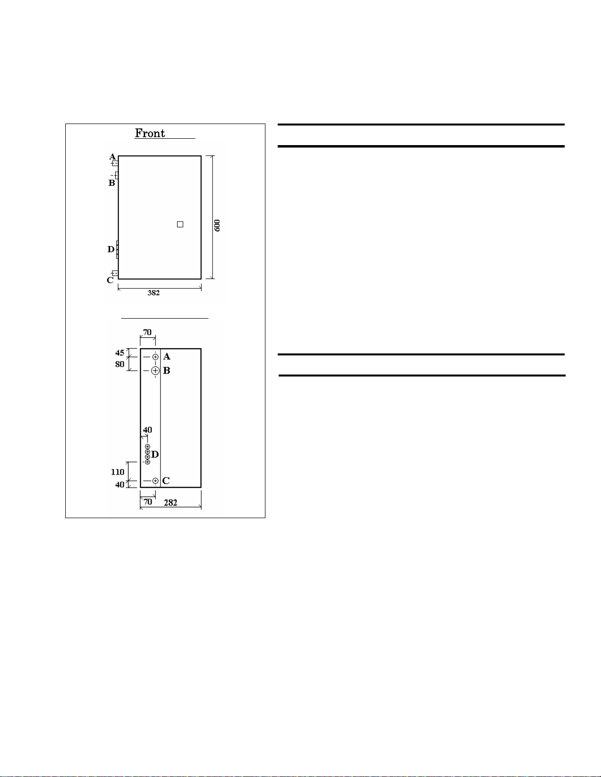
3.0 Technical Data & Dimensions
Technical Data
MECHANICAL
M1/1
Connections
4.0 Delivery Consignment / Unpacking
5.0 Locating the Pisces Minifill
View
Cold Fill Pressure Min
Minimum Mains Cold Water Supply 12 ltrs/min
Max
0.8bar
3.0bar
Power Supply (240V, 50Hz)
Motor Rated Fuse Required
Start Current 9.0 Amps
Full Load Current 2.8 Amps
Break Tank Air Gap AF
Break Tank Capacity (Max) 7.6 Ltrs
Side View (Left)
Weight (Empty) M1/1
(Filled) M1/1
10 Amps
22.0 kg
30.0 kg
Mains Cold Water Inlet (A) 15mm BSP
Waste water Outlet/Overflow (B) 28mm COMP
Water Outlet (C) 15mm COMP
Electrical Cable Glands (D) 3 x 10mm
The Pisces Minifill pressurisation manager is delivered as a single carton containing the Pisces Minifill and associated fittings.
The Pisces Minifill unit carton contains:-
•
•
•
To unpack the Pisces Minifill press urisation manager, carefully cut along the t aped seams of the carton. The carton will then
un-fold to reveal the unit. Do not discard of the packaging as this can be used as a template to assist with the inst al lation of the
unit
Assembled and Tested Pisces Minifill unit.
Wall mounting bracket. (Supplied attached to the front of the water tank.)
Installation Template (part of the carton).
The Pisces Minifill pressurisation manager is not suitable for installation external to a building. The position chosen for the
appliance shall be a structurally sound wall capable of supporting the filled weight of the appliance and all associated
ancillary equipment. The wall shall be truly plumb vertical to ensure correct operation.
Page 5

5
MECHANICAL M1/1
6.0 Installation Clearances
PISCES
MINIFILL
7.0 Wall Mounting
Important Notice
Fig 7
For ease of installation, commissioning, servicing and maintenance the following clearances should be observed.
NOTE: Thes e distances ar e M INIMUM and MUST NOT be redu ced. Failure to observe these
clearances could result in the warranties on the ap p liance becoming VOID.
The Pisces Minifill pressurisation manager can be floor
mounted, however it is recommended to be wall mounted, via
the wall-mounting bracket supplied. This bracket interlocks
into the cutout on the rear of the appliance.
A template, detailing the fixing positions and clearances, is
printed onto the appliance packaging, cut along the dotted
lines and position the template in the desired location to
ensure that all minimum clearances can be achieved.
The wall-mounting bracket should be securely fixed to the
wall using suitable fixings for the wall construction and
appliance filled weight. The w all-mounting bracket positioning
detail is shown in fig 7.
The Pisces Minifill pressurisation manager should be carefully
lifted so that the cutout on the rear of the Pisces Minifill
unit is just above the mounting bracket, and then gently
lowered to engage the bracket into the c utout. DO NOT lift the
Pisces Minifill unit by any of the internal parts or components.
When viewed from the side, the North / South axis of the
Pisces Minifill unit must be vertical
Page 6

6
PISCES
MINIFILL
MECHANICAL
M1/1
Fig 8.1
Fig 8.2
Fig 9.0
8.0 Water Connections
The Mains Cold Water Supply connection (A) shall be able
to supply at least 12 litres per minute of clean water;
otherwise the operation of the a pplianc e m ay empty the break
tank of water.
If the appliance is allowed to be operated without sufficient
water, air will be drawn into the pump assembly, which
could result in an Air Lock, and ul t im at ely damage t o the pump
assembly, which would not be covered by the manufacturing
warranty. See Fig 8.1
The Waste Water Outlet/Overflow (B) shall be routed to a
safe discharge location that will not cause harm to persons,
nor property, but shall be clearly visible, so that any water
discharge will be identified and remedial action taken,
ensuring that any wasted water i s kept to a m inimum. See Fig
8.1
The Waste Water Outlet/Overflow shall not be connected
directly to any foul water system without a suitable warning
method being incorporated, as above.
After the warning method, and before connect ion to the foul
water system a suitable trap shall be incorporated to prevent
the release of any vapour/effluent from the foul water system.
The Waste Water Outlet/Overflow shall be rout ed
in such a way to minimize the risk of blockage
through freezing. If any part of the Waste Water
Outlet/Overflow is to be run external to the
building or is at risk of freezing, then the pipe shall
be suitably insulated to protect against freezing.
The System Connection (C) shall be connected to the
system pipework in such a manner so that the
suction/discharge pressure of any circula tion pumps shall not
influence the appliance. It is recommended that the System
Connection be routed in such a manner to include/incorporate
the supply connection to any system expansion vessels. See
Fig 8.2
9.0 Electrical Connection
The Pisces Minifill pressurisation manager is supplied with a
fly lead for the Mains Power Connection; this cable should not
be replaced.
The appliance power supply, fused spur or fused plug
socket, shall be positioned within 1 metre of the unit, See Fig
9.0.
The cable size serving the unit shall be sized in accordance with
the IEE Electrical Regulation.
After the outer casing has been removed, th e Electrical
Connection rail can be located on the front-hinged inner door.
See Fig 9.1 & 9.2, on Page 7, for connections Details.
Please Note the Appliance Serial Number when
referring to these Connection Details.
Page 7

7
MECHANICAL
M1/1
PISCES
MINIFILL
9.1
Wiring Details
Drawn by:
Date:
Title.
Version:
Drg Nr
Pages:
1.1
MHS 1.1
1
Jim Wyborn
27
th
August 2015
Elco Heatin g Solu tions
3 Jun ipe r West, Fenton Way
Southfields Business Park
Basildon, Essex
SS15 6SJ Te l 0126 8 54670 0
Pisces
Minifill Wiring
Mechanical
1
2
3
4
5
6
7
8
9
10
11
12
Healthy
Healthy
Live from Pressure
Switch
Input
Input
Live to Pump
Fault
Fault
Neutral from Pump
Live
Neutral
Earth
Low
Pressure
Alarm
Volt Free
240v 0.5 amp
High
Pressure
Alarm
Volt Free
240v 0.5 amp
Used for P ump
Supply
Do not wi re to
these terminals
Mains
Supply
240v 50 Hz
10 amps
Charging
Pump
Chassis Base
Earth Tag
Front Door
Earth Tag
Rd
Pp
Pk
Yw
Or
Gy
Br
Or
Wh
Bl
Bk
GY
Bk
Bk
Scal e
Scal e
Scal e Scal e
Co ld F ill
Pressure Switch
(Fact ory set ti ng 1.0 bar)
High Pressure
Alarm Switch
(Fact ory set ti ng 2.5 bar)
Low Pressure
Alarm Switch
(Fact ory set ti ng 0.5 bar)
Connection
Details on
Pressure
Switches
BOR MOR
COM
Hours Run Meter
The High and Low Pressure Alarm switches on this model have been wired to allow Volt Free indication of Faults.
If Power Interruption of the associated Boiler / Chiller plant is required, the 240v 50Hz power s upply for the associated
Boiler / Chiller plant should be routed as follows;
Interlock Circuit In - Term 2
Link Wire Required - Terms 1 & 5
Interlock Circuit Out - Term 6
In this manner if one of the Alarm Switches are activated, the power supply to t he associated Boiler / Chiller plant will be
interrupted.
Page 8

8
PISCES
MINIFILL
10.0 Determining the Cold Fill Pressure
MECHANICAL
M1/1
Static Pressure
0.8 bar
(Height of 8.0metres, divided by 10)
Venting Allowance
0.3 bar
(Allowance from Table below)
Vapour Pressure
0.0 bar
(Allowance from Table Below)
Cold Fill Pressure
1.1 bar
(Summation of Static, Venting & Vapour Pressure)
Venting and Vapour Pressure Allowances
Allowance to ensure system can be correctly
vented.
0.0
Max Operating Temp up to 90ºC
0.2
Max Operating Temp 90ºC to 95ºC
0.5
Max Operating Temp 95ºC to 100ºC
0.8
Max Operating Temp 100ºC to 105ºC
1.2
Max Operating Temp 105ºC to 110ºC
1.6
Max Operating Temp 110ºC to 115ºC
2.0
Max Operating Temp 115ºC to 120ºC
11.1
Filling the System
i.e.
Domestic (In-House)
Fluid Category 3 (C-3)
Non Domestic (Other than In-House)
Fluid Category 4 (C-4)
The Cold Fill Pressure is critic al to the correct operation of any Pressurisation Unit and associated system. This pressure
needs to be calculated from the Static Pressure of the system (measured height in metres from the base of Pressurisation Unit
to the top of the highest part of the heating system, divided by 10 to convert to bar pressure), and an allowance for venting and
vapour pressure.
Therefore the Cold Fill Pressure, for a system with a maximum operating temperature up to 90ºC, c an be calculated as per
the example below:
Venting Allowance
Vapour Pressure
Allowance
0.3
The Pisces Minifill Mechanical M1/1 pressurisation manager cannot be used to fill the system; however, the Pisces
Minifill Electronic E1/1 and E1/2 pressurisation managers can be used to fill the system, as these appliances incorporate an
Anti-Water Wastage program.
Before the Pisces Minifill Mechanical M1/1 pressurisation manager can be commissioned, the entire Heating / Cooling /
Chilled Water system shall be filled, vented and completely flooded by a m ethod approved by the Water Regulation Advisory
Scheme (WRAS) for the type of heating system installed.
For Category 3 systems, the approved method of filling must comprise of the following components in the arrangement
shown;
•
•
•
For more information on the Pisces Minifill Electronic please contact MHS Boilers Sales Department.
Control Valve incorporating a Double Check Valve on
the Mains Cold Water pipework.
Temporary Connecting Hose, which must be
disconnected after use.
Control Valve, on the heating system.
For Category 4 systems, the approved method of filling must comprise of the following components in the arrangement
shown;
•
Control Valve.
•
Strainer.
•
Verifiable Backflow Device with Reduced Pressure
Zone (RPZ Valve)
•
Incorporating a ‘Type BA’ Air Gap.
•
Tundish.
•
Control Valve.
Page 9

9
MECHANICAL M1/1
11.2
Introduction of Water Treatment
PISCES
MINIFILL
12.1
Commissioning
12.2
First Fill and Setting to Work
before opening the isolation valve and flooding the Pisces Minifill pressurisation manager.
system will need to be treated with a suitable Water Treatment for the prevention of corrosion, scale formation and microbiological growth.
appliance as detailed below in Sect ion 12, and in t he abs ence of a suitable dos ing pot, the Wat er Treatment Chemicals may
be added to the water in the Break Tank in small doses.
that the system pressure drops and the Treated Water in the Break Tank is introduced into the system.
until the appliance turns off.
minimum of 1 hour, and then undertake a water analysis to ensure the correct dosage level has been obtain. See Section
12.0 Commissioning.
The Mains Cold Water Supply pipework MUST be thoroughly cleaned and flushed to remove debris, flux residues, etc.
After the Heating / Chilled Water system has been filled, flushed, and cleaned in accordance with BS 7593:1992, the
Some Water Treatments are supplied in a concentrated liquid form; following the successful commissioning of the
Drain an amount of water from the system (at a position some distance from the Pisces Minifill pressurisation manager), so
As the Break Tank is replenished wit h fresh water, gradually add the water treatm ent chemical (at the correct concentration)
Repeat this process until the entire water treatment chemical has been fully introduced. Let the system circulate for a
2) T he Quart er Turn Isolation Valve on the underside of the Break Tank is in the CLOSED position.
3) The Quarter Turn Isolation Valve on the Water Outlet (on the end of the flexible pipe) is in the CLOSED position.
4) The Mains Water Supply has been connected, vented, and the appliance Break Tank has been filled with clean
water. Any foreign bodies/debris are to be removed before the appliance is set to work.
5) T he Electrical Supply has been connected and tested for correct polarity.
6) T he Heating / Chilled Water system has been fully flooded and vented as detailed in Section 11.1 above.
The commissioning of a Press urisation Manager shall only be undertaken b y a competent pers on, as various safety
items associated with the safe operation of the heating / cooling / chilled water system need to be checked and
confirmed. We would therefore recommend that a Qualified Gas Safe registered engineer undertake these works.
The following Items 11.0 Filling the System, and 11.1 Set Up, needs to be completed.
Before attempting the Set Up procedure, please ensure that the following checks have been completed;
1) Check the Heating / Chilled Water system expansion vessel air charge. This vessel charge should be equal to the
calculated Cold Fill Pressure (+/- 0.2 bar) when the vessel is empty of water. See Section 10.0.
Power should not be appl ied to the appliance at t his stage.
On completion of the above checks the unit is ready to be Set Up to the system requirements, and the following procedure
shall be followed.
To Prevent duplication of setting activities, it is advisable to undertake the testing/setting of the High and Low Pressure
Alarm Switches prior to setting the Cold Fill Pressure. To prevent potential over pressurizing or loss of water treatment,
the following test shall be undertaken with the outlet value of the appliance CLOSED.
Page 10

10
PISCES
MINIFILL
12.1 First Fill and Setting to Work (cont’d)
MECHANICAL
M1/1
13.0 Fault Diagnosis
1) Open the Quarter Turn Isolation Valve on the underside of the Break Tank.
2) Vent The Pump. Located on the top of the center pipe connection of the pump assembly, is a vent valve. Undo this vent
valve with a Vent Key and release any air. When all the air has been released, securely close the vent valve.
3) To Check/Set the operation of the LOW WATER PRESSURE ALARM Switch. Turn the COLD FILL PRESSURE
adjuster to the Minimum pos ition (f ully clockwise). Turn ON the Elec tric al Power Suppl y to the applianc e, the P UMP will
operate for a short period of time. Whilst monitoring the appliance Pressure Gauge, slowly turn the COLD FILL
PRESSURE adjuster, clockwise, and the PUMP will operate t o increase the pressure. Continue th is procedure until the
appliance pressure gauge is recording the desired water pressure required for LOW WATER PRESSURE ALARM
activation. Safely remove any Electrical W ires that has been c onnec t ed to Terminals 1, 2 & 3, and make safe. Connect
a Multi-meter across Terminals 1 & 2, and check for a Closed Circuit. Using the LOW WATER PRESSURE ALARM
adjuster, turn the adjustment knob ANTI-CLOCKWISE to increase, and CLOCKWISE to de-crease, until the Circuit
Closes at the pressure displayed on the appliance pressure gauge. Record the Pressure Setting on the Commissioning
Form on Page 12. Re-connect any Electrical Wires previo usly removed from Term inals 1, 2 & 3. Factory Setting Cut-
Out 0.5 Ba r, Cut-In 0.9bar (+/- 0.1 bar).
4) To Check/Set the operation of the HIGH WATER PRESSURE ALARM Switch. Gradually turn the COLD FILL
PRESSURE adjuster slowly towards the Maximum position (anti-clockwise). The PUMP will operate for a sho rt period of
time with every adjustment. Whilst monitoring the appliance Pressure Gauge, continue to slowly turn the COLD FILL
PRESSURE adjuster (anti-clockwise) until the appliance pressure gauge is recording the desired water pressure
required for HIGH WAT ER PRE SSURE ALAR M act ivation. Safely remove any Electrical Wires that has been connected
to Terminals 4, 5, & 6, and make safe. Connect a Multi-meter across Terminals 5 & 6, and check for a Closed Circuit.
Using the HIGH WATER PRESSURE ALARM adjuster, turn the adjustment knob ANTI-CLOCKWISE to increase, and
CLOCKWISE to de-crease, until the Circuit Closes at the pressure dis played on the appliance pressure gauge. Record
the Pressure Setting on t he Commissioning Form on Page 12. Re-connect any Electrical Wires previously removed from
Terminals 4, 5 & 6. Factory Set t ing Cut -Out 2.7 Ba r, Cut-In 2. 3 ba r (+/- 0.1 bar).
5) To Set the COLD FILL PRESSURE, firstly turn OFF the Electrical Power Supply to the Appliance and connect a
small tube to the Drain Valve. Slowly loosen the bleed screw to drain water from the Drain Valve. Continue to drain the
appliance until the pressure gauge indicates the desired COLD FILL PRESSURE. Turn the COLD FILL PRESSURE
adjuster to the minimum position (clockwise). Turn ON the Electrical Power Supply to the appliance, the PUMP should
not be running at this point. Gradually turn the COLD FILL PRESSURE adjuster until the PUMP turns ON. The PUMP
should continue to operate until a pressure increase of 0.4 bar has been detected and the PUMP should then turn OFF.
Record the Pressure Setting on the Comm issioning Form on Page 12. Fac t ory Sett in g Cut -In 1 .4 ba r, Cut-Out 1.0 Bar
(+/- 0.1 bar).
6) Open the Quarter Turn Isolation Valve on the Water Outlet (on the end of the Flexible Hose). The Pressure Gauge will
now be recording the Current System Pressure (+/- 0. 1 bar). Care should be take n to ensure t he appliance is not
exposed to a backpressure in excess of 3.0 bar from the Heating / Chilled Water System.
7) Open a drain facility on the system (as close to the Pressurisation Management Unit as possible) so that a gradual
pressure loss is achieved. Monitor the Pressure Gauge on the Appliance and check that the Pump Cuts-In/Cuts-Out to
replenish the system water at the required pressure, as set/recorded in Item 5 above. Repeat Item 5 if the pressure
maintained is incorrect.
8) Close the drain facility on the system, and check that the Pump Cuts-Out as required.
Should a problem occur with the operation of the appliance, the following procedures should be referenced. Further
technical assistance is available from our MHS Boilers Technical Services Department, on 01268 546700, during normal office
hours.
Symptom Remedial Action
Pump Running, pressure not
rising, but NO new water
input into Break Tank
• Pump Impeller Failure, replace Pump Assembly.
•
Mains Cold Water Supply turned OFF.
•
Quarter Turn Isolation Valve on the underside of the Break Tank
closed / blocked.
•
Quarter Turn Isolation Valve on the Water Outlet closed / blocked.
•
Break Tank empty of water.
•
Pump Assembly Air Locked.
•
Non Return Valve on outlet of Pump Assembly blocked.
Page 11

11
MECHANICAL M1/1
13.0 Fault Diagnosis (cont’d)
PISCES
MINIFILL
14.0 Internal Components & Short Parts List
1 2 3 4 5
Symptom Remedial Action
Pump Running, pressure not rising, but water input into Break Tank
Pressure Low and Pump will
not run.
Pressure High and Pump
won’t turn OFF.
High Pressure Alarm, pump
not running.
needed.
•
Turn OFF Quarter Turn Isolation Valve on the Water Outl et , If
pressure rises and pu mps turns OFF, System h as a leak equal
or greater than the applianc e c an replenish. Check System.
•
Check Mains Power Supply.
•
Check Power Supply to Pump Unit (Term 8)
If power - PUMP faulty, inspect / replace as needed.
If NO power - check operation of COLD FILL pressure switch and
adjust / replace as needed.
•
Check COLD FILL PRESSURE switch for correct operation, and
adjust / replace as needed.
•
Check system expansion vessel for correct air charge.
•
Check COLD FILL PRESSURE switch for correct operation, and
adjust / replace as needed.
•
Check Setting of HIGH PRESSURE ALARM switch and adjust as
1
2
3
6
7
2x M10
Bolts
Please Note:
5
8 4
Description Part No
Item
No
Cold F i ll Pressure
Switch
High Pressure
Alarm Switch
Low Pressure
Alarm Switch
Pump Assembly
(Complete)
Pump Inlet
Isolation Valve
6
Outlet Drain Valve
Multi-way
7
Pressure
Connector
Plastic Pipework
8
Assembly Including
Isolation Valve
Outlet Isolation
Valve Complete
with F lexib le Pipe.
(Not Shown)
Ball Float Valve
(Not Shown)
Hour Run Meter
(Not Shown)
The Pump Assembly (Item 4) is mounted onto a removable pump tray. To remove, disconnect all wa t e r joints,
remove the two M10 bolts (A), slightly lift the front of the pump tray and slide the tray forward, this will dis- engage
the three location posts at the top of the tray. The tray and pump assembly can then be removed from the
appliance.
PM840002
PM840002
PM840002
PM010044
CP920011
PF920005
PM070004
PM010034
PF940005
CP000001
EL930001
Page 12

12
PISCES
MINIFILL
15.0 Commissioning Form
MECHANICAL
M1/1
Comments:
The comm issionin g engineer s hould com plete this section o n the day of S etting Up the appliance;
so that a record is kept of the set tings made for future reference.
ENGINEER: COMPANY:
DATE: SERIAL NO:
RESULTS SETTING
System Static Height metres
Cold Fill Pressure
System Vessel Size litres
System Vessel Air Charge
Maximum System Operating Temperature
System Safety Valve Setting
bar
bar
ºC
bar
Final W orking Pressure of Syst em (Hot) bar
High Pressure Alarm Switch Setting
Low Pressure Alarm Switch Setting
bar
bar
High Pressure F ault Test Yes/No
Low Pressure F ault Test Yes /No
Hour Run Meter Reading Hours
3 Juniper West, Fenton Way, Basildon, Essex, SS15 6SJ Tel: 01268 546700. Fax: 01268 888250
This publication is issued subject to alterat io n or withdraw al witho ut notice. The il lustrations and specifications are n ot binding in detail. All
offers and sales are subject to the Company’s current terms and condition of sale.
05/01/16
 Loading...