

elco Low-NOx N10.12000.37 G-EU2, Low-NOx N10.14000.37 G-EU2, Low-NOx N10.12000.30 G-EU2, Low-NOx N10.14000.45 G-EU2 FQ, Low-NOx N10.16000.45 G-EU2 FQ Operation Manual
Page 1

Operation manual
for the authorized specialist
Gas forced draught burner Low-NO
x
N10... G-EU2
12/2011 14 072 205
Page 2

2
Inhalt
Overview Contents ................................................................................................................ 2
Important information Warranty, safety instructions .............................................. 3
Safety instructions Installation, start-up, maintenance .......................................... 4
Technical data .............................................................................................................................. 5
Important components, burner description ............................................................ 6
Operation fields ..................................................................................................... 7
Operation fields ..................................................................................................... 8
Gas pressure loss burner head Gas pressure loss gas butterfly .......................... 9
Dimensional drawing ........................................................................................... 10
Installation conditions .......................................................................................... 11
Installation Mounting to boiler Electrical connection Presetting ............................................ 12
Burner head settings ........................................................................................... 13
Gas connection ................................................................................................... 14
Gas train description ........................................................................................... 15
Start-up Checking procedure ............................................................................................ 17
Disassembling firing head ................................................................................... 18
Gas start-up mode Gas operating mode General safety function ....................... 19
Fuel-air compound control .................................................................................. 20
Electronic burner controller ................................................................................. 21
Servo motor type SAD 15 ................................................................................... 22
Electrical actuator STM 40 .................................................................................. 22
Flame sensor ...................................................................................................... 23
Gas pressure switch Air pressure switch ............................................................ 24
Adjustment Combination controls CG 15 -30 ...................................................... 25
Exhaust gas test .................................................................................................. 27
Servicing instructions Burner maintenance ............................................................................................ 29
Fan impeller ........................................................................................................ 30
Trouble shooting instructions Cause and removal of disturbance ..................................................................... 31
Manufacturer’s declaration ............................................................................................................................ 33
Overview
Contents
12/2011 14 072 205
Page 3

3
Overview
Important information
Warranty, safety instructions
General information
These operating instructions are a fixed
component of the system which should
be displayed in a prominent location at
the point of installation of the heat generator and should include the address
and telephone number of the nearest
customer service centre.
They are directed solely at authorised
expert personnel.
These operating instructions cont ain
the most important information for
installing, commissioning and maintaining the burner safely and must
be observed by any personnel who
work on the system.
Important information
The burners are designed in accordance with the specification in the Technical data section (alternative fuels on
request).
The burners should be installed and
taken into operation carefully by qualified personnel. The work should be
done in accordance with the applicable
regulations and guidelines.
Only a duly authorised specialist should
be entrusted with the installation of the
gas system, and all applicable directives and regulations must be observed.
Any repair work on monitors, limiters
and automatic furnace controllers and
on the other safety facilities are allowed
to be done on the single items only by
the manufacturers themselves or specialists authorized by them.
Original parts should only be exchanged by a duly qualified specialist.
Standards and regulations
The following standards should be
observed in the interest of a safe, easyon-the-environment and energy-saving
operation of the burner:
The operator must, in accordance with
country-specific standards and legislation, be given instruction on how the
heating installation operates.
National requirements and building regulations must be taken into consideration during installation of a gas-fired
system.
Screwed unions of metal used in gas
lines should be fitted with approved
sealing elements.
Prior to taking the burner into operation
make sure to vent the gas line, but this
should in no case be done through the
furnace chamber.
Place of installation
The burner must not be operated in
rooms containing corrosive vapours
(e.g. spray, perchloroethylene, hydrocarbon tetrachloride, solvent, etc.) or
tending to heavy dust formation or high
air humidity.
Adequate ventilation must be provided
at the place of installation of the furnace
system to ensure a reliable supply with
combustion air.
Maintenance
The furnace system should be serviced
at least once a year by an authorized
specialist. It is recommended to conclude a maintenance agreement to this
effect.
Guarantee
The guarantee does not cover damage resulting from:
- failure to commission and maintain the
burner in accordance with the operating instructions;
- damage or loss arising from incorrect
installation;
- damage or loss arising from incorrect
adjustment;
- damage or loss arising from unauthorised tampering and
- damage or loss arising from improper
operation (e.g. operating the system
at excessive pressure).
Subject to change without notice due to
ongoing technical developments.
EN 676 Gas burners with
blowers
Safety instructions
The burner has been built and tested to
applicable standards and directives and
recognised rules of technical safety
and, depending on the burner type, has
either been type tested (see declaration
of conformity in the Technical data
section) or must be tested individually
(see manufacturer's declaration in the
Technical data section). Risks to
persons or property may arise if the
burner is not operated correctly or used
for its intended purpose.
To eliminate these risks, the burner
may only be installed and operated
• in accordance with its intended
purpose
• in a technically safe condition
• in compliance with all guidelines and
information contained in these
operating instructions
• in compliance with all inspection and
maintenance guidelines, as specified
in the operating instructions or
components documentation, or as
defined by applicable national
legislation, standards or requirements.
Safety measures and rules of
conduct
1. Burner only to be operated in an
undamaged, defect-free and
technically safe condition.
2. Assembly, commissioning /
adjustments, repair and maintenance
carried out only by experts trained and
authorised for the work concerned.
This also applies to work on the
electrical system and the gas/oil
supply.
3. All safety devices of the system must
be checked on a regular basis as
specified by applicable regulations.
4. Protective clothing must be worn
while work is being carried out on the
system.
5. The information in the operating
instructions must be observed as well
as the applicable requirements or
regulations of accident prevention and
relevant national construction and
safety regulations, requirements,
standards and legislation.
6. The markings on the system must be
maintained in a clearly readable
condition and restored if necessary.
12/2011 14 072 205
Page 4

4
Overview
Important information
Safety instructions
Installation, start-up, maintenance
7. Equipment to be operated only with
safety devices activated and in good
working order.
8. The system must be checked
annually – or more frequently if
necessary, depending on system
conditions - for externally visible
damage and for the correct operation
of safety devices.
9.Safety functions and safety times
must not be impaired, rendered
inoperational or modified by additional
external wiring.
Tasks carried out on the electrical system
• All tasks involving the electrical
system must be carried out by expert
electricians.
• Before any work is carried out, the
system must be disconnected from
the power supply and secured against
unexpected reconnection.
• Work on live systems may only be
carried out under the supervision of a
second person who would be able to
disconnect the power supply in the
event of danger.
• The electrical system must be
routinely checked as part of
maintenance. Damage of any kind
(e.g. loose connections, damaged
cable insulation) must be rectified
immediately.
Safety instructions for assembly
Always disconnect the system from
the power supply!
Before assembly work begins, switch
off the master and emergency switches
and secure them against the possibility
of being switched back on.
Danger! Failure to comply could result
in a harmful or fatal electrical shock.
Risk of severe injury and danger of
death.
Safety instructions for initial
commissioning
The initial commissioning of the heating
installation must only be carried out by
the constructor, manufacturer or
another of the experts described. All
regulating, control and safety devices
must be checked for correct operation
and – where adjustment is possible –
for correct adjustment.
Before initial commissioning, it is
necessary to check electrical circuits for
correct fusing, and the measures for
protection against accidental contact
with electrical equipment and wiring.
Safety instructions for
maintenance
• The operator must be informed of all
work to be carried out before it begins.
• Assembly, commissioning /
adjustments, repair and maintenance
carried out only by experts trained and
authorised for the work concerned.
This also applies in particular to work
on the electrical system and the gas/
oil supply.
• Protective clothing must be worn while
work is being carried out on the
system.
• Specified adjustment, maintenance
and inspection work must be carried
out at the specified intervals.
• Before any work is carried out on the
system, the system must be
disconnected from the power supply
and secured against unexpected
reconnection.
• The fuel supply must be closed before
work is carried out on the system.
• All safety devices of the system must
be checked on a regular basis as
specified by national requirements,
regulations, standards and legislation.
• Damaged system parts must be
replaced immediately. If parts are to
be replaced, it is only permitted to use
genuine parts, or replacement parts
that have been approved or
authorised by the manufacturer.
• The installation of additional
components that were not subjected
to model series or individual testing at
the same time as the system is not
permitted.
• Do not modify the system or fit
attachment or conversion parts
without the authorisation of the
manufacturer.
• Loose connections must be checked
for firm seating after they have been
reconnected.
• If seal connections are opened, the
sealing surfaces must be cleaned
thoroughly at the time of reassembly.
Ensure a perfect connection;
damaged seals must be replaced with
new ones. Check for leaks once
reassembly is complete.
• Repairs to limiting devices, automated
equipment, flame monitoring
equipment and other safety devices
must only be carried out by the
manufacturer or its appointed
representatives. The expert charged
with carrying out maintenance work
must replace complete components or
assemblies with those of the same
type.
• Safety devices must be checked for
correct operation following their
replacement or repair and after any
maintenance work has been
completed.
• Only use the burner with furnaces that
are suitable for the flame dimension
concerned, i.e. in which the flame may
burn out unhindered.
• Any change to the furnace pressure
(e.g. as a consequence of
modifications to the flue system), and
any modification that would result in a
change in the supply of air to the
burner (e.g. a retrofitted
soundproofing shroud), requires
reconfiguration of burner regulation.
• Persons present in the proximity
during burner operation must be
equipped with suitable measures for
protection against harmful noise
levels.
After all maintenance and repair
work:
1. Function test.
2. At all load points, check O
2
- (CO2-) /
CO -/ NOx- values, soot emissions
and exhaust gas losses.
3. Create a measurement report, leave
a copy with the system.
12/2011 14 072 205
Page 5
5
Technical data
Burner type
N10.12000.30
G-EU2
N10.12000.37
G-EU2
N10.14000.37
G-EU2
N10.14000.45
G-EU2 FQ
N10.16000.45
G-EU2 FQ
Combustion power
output
(*FQe=frequency converter
for motor externally)
1.500* - 12.000 kW
*(1.750 kW without
FQe or Natural gas
LL)
1.500* - 12.000 kW
*(1.750 kW without
FQe or Natural gas
LL)
1.750* - 14.000 kW
*(2.000 kW without
FQe or Natural gas
LL)
1.750 - 14.000 kW 2000 - 16.000 kW
Max. control ratio 1:8 for Natural gas E and with FQe
1:7 without FQe or Natural gas LL
Deviating values on request
(N.B.: the lower operating point must also be within the working field.)
Boiler furnace
pressure
Selection of the nominal burner capacity within the nominal capacity area marked in the working
field. Deviating nominal capacities on request. At burners with FQ higher furnace back pressure by
rise of the motor frequency to > 50 Hz up to the max. capacity limit.
Fuels Natural gas E, LL
Operation type Continuously modulating
Electronic air-fuel-
compound-control,
automatic firing
device
Etamatic OEM or BCS 300 on burner
Alternative electronic burner controls in separate cabinet
Electrotechnical
equipment
Attached to the burner is an IP54 control cabinet that contains the terminal block and, where applicable, the combustion manager and other components
Optional electrotechnical equipment
BCS or Etamatic OEM as burner controller
Power controller with protection, soft start or Y-D start externally in a separate control cabinet
Power regulation by external 4-20 mA nominal value input
Frequency converter externally in a separate control cabinet
Preparation for controller-specific O
2
regulation, probe fitted externally
Profibus DP, Modbus RT, Ethernet
Fan motor 400/690 V, 50/ 60 Hz / 2950 U/min, IP55
30 kW 37 kW 37 kW 45 kW 45 kW
Gas connection DN100, PN16, Natural gas E p
min
=250 mbar, Natural gas LL p
min
=300 mbar
Protection class IP40, IP54 as option
NOx-emissions Emission class 3 according EN 676, 70-150mg/kWh (0% O
2
acc. EN 676)
Precise values on request.
Flame length max. at
3% O
2
6,0 m 6,0 m 6,4 m 6,4 m 6,8 m
Flame diameter
min. 1,3 - 1,6 m
(depending on combustion output
and NOx requirements)
min. 1,4 - 1,75 m
(depending on combustion output and NOx requirements)
Acoustic
Emissions, Sound
Pressure
< 97 dB(A) (average value on enveloping surface at 1 m distance)
Site Closed rooms or weatherproof on site; non-aggressive atmosphere
Ambient temperature
(including impact of heat
radiation)
0°C - 60°C with BCS or Etamatic on burner,
-10°C - 60°C with alternative electronic burner controls in switch cabinet,
relative humidity max. 60% (special corrosion protection on request)
Burner weight Approx. 550 kg plus 100 kg for transport rack
12/2011 14 072 205
Page 6
6
Technical data
Important components, burner description
important
components:
Flame monitor QRA 2, QRA 53 / FFS 06
Ignition transformer EBI
Servo motor SAD15 / STM 30/40
Air pressure switch DL 50 A
Burner type
N10.12000.30
G-EU2
N10.12000.37
G-EU2
N10.14000.37
G-EU2
N10.14000.45
G-EU2 FQ
N10.16000.45
G-EU2 FQ
Operating mode
The burner is designed as an automatic
controllable gas blast burner to EN 437
Gasfamily 2. It is tested according to
EN 676 and fitted with a delta burner
head, a system for the low NO
x
combu-
stion of fuel.
Application
The burners are applicable for the operation at heating boilers, steam boilers
and air heater with 3-pass, draft or
reverse furnace.
Design
The burner is supplied with connection
leads fixed to a terminal block ready for
connection to the boiler system.
BCS and Etamatic OEM design
The burner is equipped with an electronic burner control system (automatic
furnace controller, electronic compound
controller, gas valve leak detector).
Other electronic burner controller
Electronic burner control (automatic furnace controller, electronic compound
controller, gas valve leak detector) is
placed in the separated switch cabinet.
Combustion air
An overpressure fan impeller with a
steep characteristic is provided to
ensure a high pressure build-up. This
ensures a pulsation-free and steady
combustion behaviour also on boilers
with a high exhaust gas resistance.
Control
The fuel-air ratio is controlled by an
electronic compound controller with
actuators provided for positioning the
following control elements:
- air damper,
- gas damper.
- event. frequency inverter.
Sensors
A flame sensor and an approved automatic furnace controller are provided for
flame monitoring. An differential pressure switch is fitted for fan air monitoring. A speed monitor is installed if an
automatic speed control system is
used.
Ignition
Electrical high voltage ignition of the
enclosed ignition burner.
Heat capacity of the ignition flame
< 10% of the main flame.
Internal exhaust gas return
As a primary precaution to minimize the
generation of nitric oxides, the delta
burner head will internally extract combustion gases from the furnace chamber and feed them to the fuel mixture.
This concept does away with the equipment otherwise required for the external
return of the exhaust gases.
12/2011 14 072 205
Page 7
7
Technical data
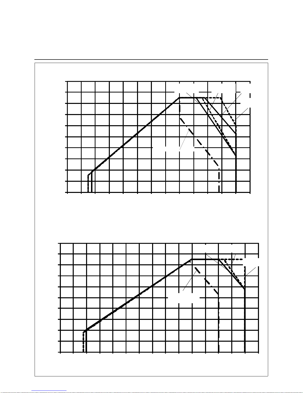
Operation fields
0
4
8
12
16
20
24
28
32
36
40
012345678910111213
A rbei tsfel der N10.12000 G- EU2 nach EN 676
0
4
8
12
16
20
24
28
32
36
40
0 1 2 3 4 5 6 7 8 9 10 11 12 13 14 15
Arbeitsfelder N10.14000 G-EU2 nach EN 676
Combustion power output [MW]
Limit full load range
Boiler furnace pressure [mbar]
Operation fields N10.12000 G-EU2 according EN 676
Operation fields N10.14000 G-EU2 according EN 676
Combustion power output [MW]
Boiler furnace pressure [mbar]
FQe=frequency converter for motor externally
FQe=frequency converter for motor externally
N10.14000.45
G-EU2 FQe
N10.14000.37
G-EU2 FQe
Limit full load range
N10.14000.37
G-EU2
N10.12000.30
G-EU2
N10.12000.30
G-EU2 FQe
N10.12000.37
G-EU2
N10.12000.37
G-EU2 FQe
12/2011 14 072 205
Page 8
8
0
5
10
15
20
25
30
35
40
45
50
55
01234567891011121314151617
Arbeitsfeld N10.16000.45 G-E FQ
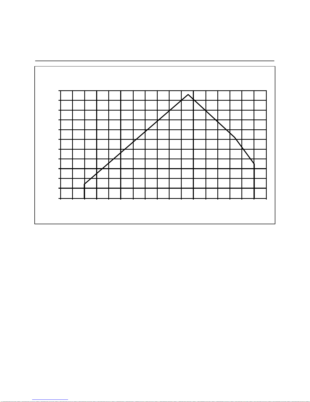
Operation fields N10.16000 G-EU2 FQe according EN 676
Technical data
Operation fields
Combustion power output [MW]
Boiler furnace pressure [mbar]
FQe=frequency converter for motor externally
12/2011 14 072 205
Page 9
9
Technical data
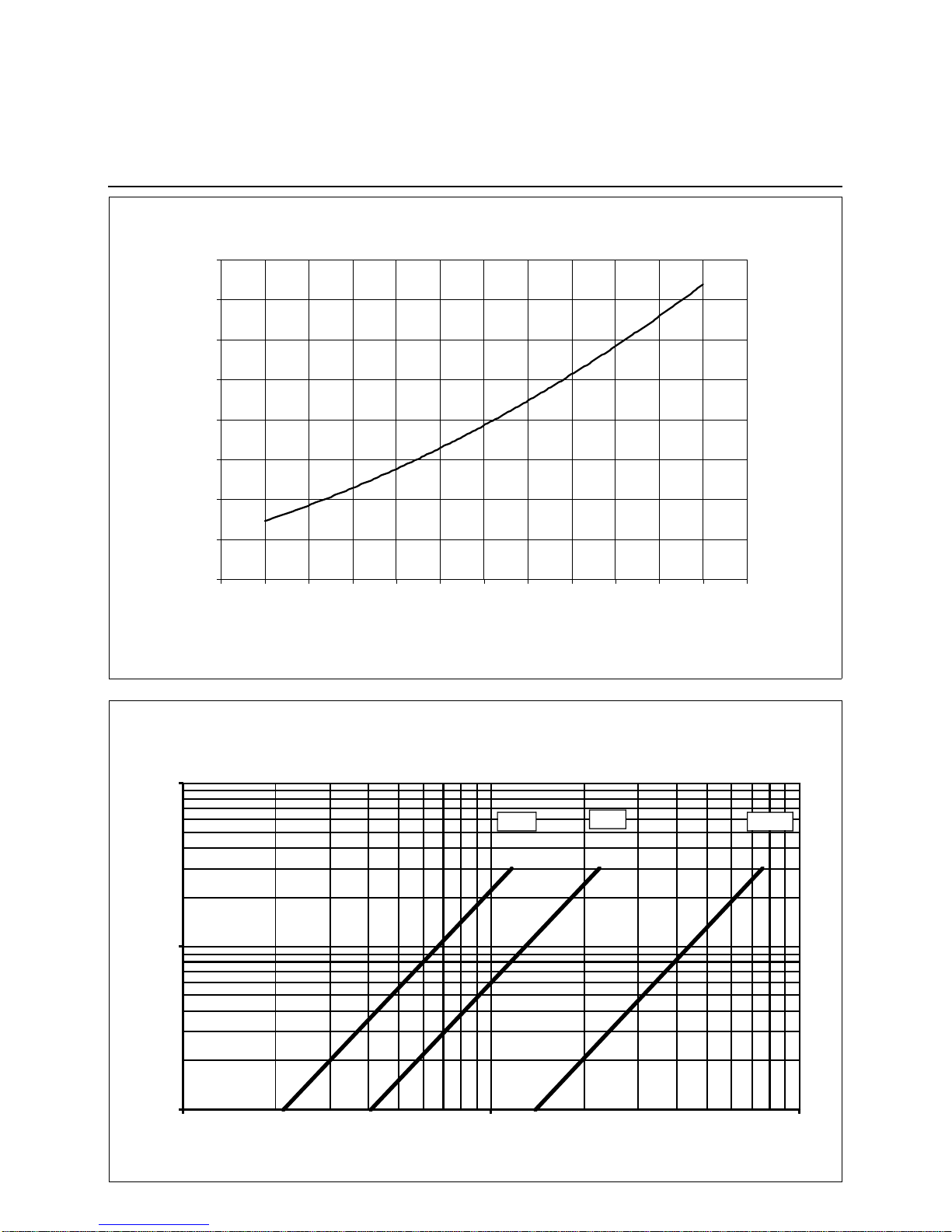
Gas pressure loss burner head
Gas pressure loss gas butterfly
Druckverluste G as Mischeinrichtung E10 G-EU 2
0
20
40
60
80
100
120
140
160
700 800 900 1000 1100 1200 1300 1400 1500 1600 1700 1800 1900
Volumenstrom Erdgas [m³ /h], 15° C, 1013 mbar, dv 0,61
Druckverl u st [ m bar]
Operation volume flow natural gas [m3/h], t=15°C, 1013 mbar, dv=0,61
p p
diagr
T
288
----------
1013
p
-------------
dv
061,
-------------
=
Pressure loss [mbar]
Pressure loss gas mixed unit N10 ... G-EU2
1
10
100
100 1000 10000
D
r
u
c
k
v
e
r
l
u
s
t
[
m
b
a
r
]
Vol um enst r om V [m ³ /h ], Erdgas, 15 ° C, 1013 mbar, dv = 0,62
Druckverlust b ei voll geöffneter Gasklappe DN 100 Typ DKG / BVG
Ø 100 Ø 65
Ø 80
Pressure loss gas butterfly (full open) DN 100 type DKG/BVG
Operation volume flow natural gas [m3/h], t=15°C, 1013 mbar, dv=0,62
Pressure loss [mbar]
12/2011 14 072 205
Page 10
10
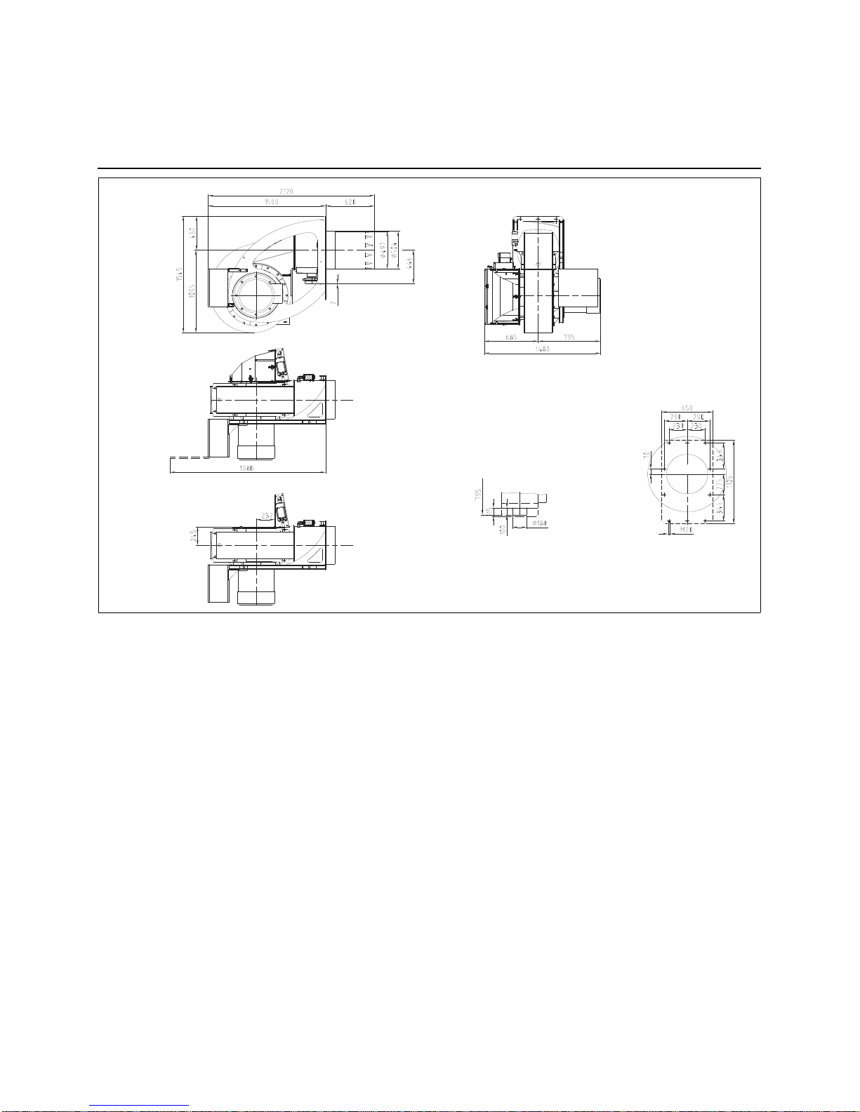
Technical data
Dimensional drawing
N 10... G-EU2
The cover of motor is
removable in case of opening boiler door for revision
Motor with disassembled protection grid
Drilling Template
Air intake box cover with
dismantled home
12/2011 14 072 205
Page 11

11
Technical data
Installation conditions
ad 1) Boiler lining
D = 497
D
1
= 525
DF= combustion chamber
diameter
T
1
= 150-250
A = 620
(option: extensions
of 100 and 200 mm)
The burner lining must be installed at
right angles to the burner tube.
Possible trimming work (bevelling, rounding) as is required for reversing boilers, for example, should done at a
diameter not below 70 % of the combustion chamber diameter.
The space between the flame pipe of
the burner and the boiler lining should
be lined with heat resistant material,
such as Cerafelt.
This space is not allowed to be lined
with brickwork.
Minimum distance on double
flame tube boilers
ad 3)
Note:
In special cases, the air infake box can
be mounted in a way that the opening
shows to another direction. The dimensioned drawing will the differ slightly.
The air intake box can be rotated in
steps of 22,5 °..
3)
1)
2)
12/2011 14 072 205
Page 12

12
Installation
Mounting to boiler
Electrical connection
Presetting
Check before burner installation
Check the mixing unit for correct setting; see dimensioned drawing.
Deviations from the burner head adjustment data may be acceptable following
a type test or individual testing by
arrangement with the test authority in
order to adapt the burner to the boiler
and flue gas system. However, these
deviating adjustments must be carried
out by an authorised expert and all
modified dimensions must be documented in the adjustments and measurements log containing the flue gas
measurement and combustion stability
evaluation. This must be handed over
to the test authority on request.
- Set the ignition electrodes according
to the sketch.
- Check the burner pipe mounting
according to Section “Boiler lining for
burners” and the boiler manufacturer’s
specifications.
Electric connection:
The electric connection including all
installation materials as well as joints
and earth terminals must be made in
accordance with the applicable regulations. For the electrical installation of the
burner reference should be made to the
circuit diagram of the furnace system.
The electric connection of the burner
and gas valves and instruments is allowed to be entrusted to authorized specialists only.
Burner installation
For mounting the burner to the boiler
make sure the connection plate is prepared in accordance with the dimensions given in the technical datasheets.
• Install the stud bolts in the connection
plate.
• Put the insulating base and burner in
place and fasten with bolts.
Arrangement of sealing tape on
the boiler (1)
- Evenly stick on self-adhesive tape (2)
according to Figure.
- Adapt the flat gasket by cutting to the
boreholes in the area of the four. vertically arranged boiler fastening holes.
(3)
- In case of butt joints make sure the
bordering is fitting closely. (4)
Attention:
After the completion of the electric connection work make a check of the wiring
of the burner electric system. This includes a check for the direction of rotation
of the burner motor (fan).
Boiler inspection glass cooling
For cooling and cleaning the boiler
inspection glass, a cooling line (e.g. a
hose) may be installed from the burner
to the inspection glass. A connection
piece is provided on the burner for this
purpose.
Burner plate with gasket strip
12/2011 14 072 205
Page 13

13
Installation
Burner head settings
N 10.... G-EU2
Burner ABC D D1EXY
N10.12000 G-EU2 620 155 118 491/497 375 65 30 10
N10.14000 G-EU2 620 155 118 491/497 338 65 30 10
N10.16000 G-EU2 620 155 118 491/497 338 65 30 10
Adjustment electrical Ignition Operation Gas ignition burner ZB 2
Ignition burner gas pressure [mbar]
Blower pressure p [mbar]
12/2011 14 072 205
Page 14

14
Installation
Gas connection
Gas connection
The gas lines and valves and instruments group should be installed and
taken into operation in accordance with
the applicable engineering standards
and regulations.
The connection between the gas distribution network and the gas ramp must
be done by authorised persons.
The section of the pipings must be calculated so that the loss of load doesn’t
exceed 5% of the distribution pressure.
A quarter turn manual valve (not supplied) must be provided for upstream of
the gas ramp and the filter.
The filter must be installed on a horizontal nozzle with the cover in the vertical position to enable cleaning.
The threaded unions used must be in
conformity with present standards
(tapered male thread, straight female
thread with sealing provided in the
thread).
Gas properties
Prior to any installation work make sure
to obtain the following data from the gas
supply company:
1. type of gas
2. calorific value Hu
n
=kW/m³ (kJ/m³)
3. maximum CO
2
content of exhaust
gas
4. gas connection pressure and rest
pressure
Type of gas test
Prior to mounting the burner to the gas
feed line check the available type of gas
and burner type against the data given
on the burner nameplate (attached to
burner). Be sure the description of the
burner and the type of gas are the
same as indicated on the nameplate.
Gas connection pressure
A minimum connection pressure must
be available upstream of the burner gas
valve to ensure the proper functioning
of the burner.
For the installation of the valves and
instruments group take care to observe
the mounting instructions supplied by
their manufacturers (these are packed
with the equipment).
The gas line installed to the burner
must be dimensioned in accordance
with the throughput rate and the available pressure.
For selecting the nominal bore „DN“ of
the gas valves and instruments group
care should be taken to observe the
flue resistance of the boiler and the
gas pressure loss of the burner and
valves and instruments group.
Caution!
The absence of impurities and foreign
bodies must be checked before installation and commissioning of the gas
ramp, the lever valves and unions.
Gas valves and instruments
group
The gas valves and instruments group
can be connected directly to the gas
feed line.
T a ke care to observe the
correct order of installation and
direction of flow (arrow on housing).
Check the valves and instruments and
connection pieces for absence of dirt
particles and foreign matter before
installation and initial operation.
T o provide effective conditions for start-up
make sure the distance between the
burner and the gas stop valve is as
short as possible.
Leak test
The gas line upstream of the burner gas
valves and instruments group must be
installed in accordance with the applicable regulations, checked for absence of
leaks, vented and certified accordingly
by the gas installation company. The
screwed unions and flanged joints must
be checked for proper tightness (by
making a pressure test). The leak test
must be made under pressure using
approved foaming agents which do not
cause corrosion. For steam boiler furnaces the result of the leak test must be
duly certified.
Venting
Caution! Prior to taking the burner into
operation or after any repair work make
sure to vent the complete gas feed line
and the gas valves and instruments
group into the open atmosphere (e.g.
by means of a hose) taking care to
avoid any hazards.
In no case should the gas line be
vented into the heating or furnace
chambers.
Make use of a test burner to check the
gas-carrying spaces are free from an
inflammable gas mixture.
Support
The valves and instruments group must
be supported with at least one telescopic jacking member or similar during
and after installation (e.g. on filter and
valve).
Joint
It is recommended to provide an easyto-disconnect joint (with planar sealing
faces) to facilitate repair work on the
boiler (furnace) and allow the boiler
door to be swivelled out if required.
12/2011 14 072 205
Page 15

15
Installation
Gas train description
The burner's scope of delivery may
include a gas train. In this case, the burner and the gas train are issued with a
CE Declaration of Conformity. If the gas
train is not delivered with the burner, the
conformity of the burner is valid only if
the gas fittings and instruments and the
design of the gas train satisfy the burner test specified by EN 676 and meet
the Pressure Equipment Directive. Individual testing will be necessary where
this is not the case.
The gas train delivered has its own
documentation including operating
instructions and a spare parts list.
There follows a general description of
the gas train.
Gas trains with a double valve are
intended for the supply, main shut-off,
gas filtration, gas pressure regulation
and monitoring of the gas supply. They
are compatible for use with gases conforming to the specifications of the gas
fittings and instruments. They are built
in accordance with EN 676. All function
parts have been individually tested and
awarded the CE marking and number
of the Notified Body. The preassembled
gas train is checked for leaks in the factory.
Low- and high-pressure gas
trains
If the outlet side of the regulator, i.e.
individual fittings and instruments
downstream of the gas pressure regulator, has not been designed to be compatible with the maximum supply
pressure that occurs in the event of a
fault, the gas train must be equipped
with a safety shut-off valve (SSV) and a
safety relief valve (SRV) in accordance
with EN 676. This equipment is generally required for maximum supply pressures of >360 mbar and > 500 mbar
respectively. These are known as highpressure gas trains.
If all fittings and instruments of the gas
train have been designed/approved for
the maximum supply pressure that
occurs in the event of a fault, the gas
train is known as a low-pressure gas
train. This is the case, depending on
component selection, for maximum
supply pressures of 360 and 500 mbar.
101
100 Burner
101 Impulse pipe gas pressure
120 Air flap
141 Ball valve
142 Gas filter
150 Gas control butterfly
151 Gas double valve (Siemens system illustrated)
155 Ignition unit
313 Min. gas pressure switch
314 Gas pressure switch for valve leak check or valve leak
checker
349 Actuator
Options in accordance with country-specific requirements:
143 Pressure gauge with pushbutton valve
147 Test burner with pushbutton valve
148 Compensator
154 Gas safety valve (additional)
313a Max. gas pressure switch
Gas train to EN 676, low pressure
12/2011 14 072 205
Page 16

16
Installation
Gas train description
Gas valves and instruments
group
The gas trains must be dimensioned to
suit the throughput required and the
available gas pressure. The gas valves
and instruments group is defined on a
system-specific basis.
The following must be taken into consideration:
• Burner output,
• Combustion chamber counterpres
sure,
• Gas pressure loss in the burner head,
• Gas pressure losses in the gas fit
tings and instruments.
The total drop in gas pressure must
always be lower than the available gas
flow pressure.
100 Burner
101 Impulse pipe gas pressure
120 Air flap
141 Ball valve
142 Gas filter
144 Gas pressure regulator
145 Safety shut-off valve (SSV)
148 Safety relief valve (SRV)
150 Gas control butterfly
151 Gas double valve with integrated gas pressure
regulator (Siemens system illustrated)
155 Ignition unit
313 Min. gas pressure switch
314 Gas pressure switch for valve leak check or valve
leak checker
349 Actuator
Options in accordance with country-specific requirements:
143 Pressure gauge with pushbutton valve
147 Test burner with pushbutton valve
148 Compensator
154 Gas safety valve (additional)
313a Max. gas pressure switch
Gas train to EN 676, high pressure
12/2011 14 072 205
Page 17

17
Start-up
Checking procedure
Check the following prior to the
initial operation of the boiler system:
• Take care to observe the operating
instructions supplied by the boiler
manufacturer. The boiler must be
mounted ready for operation.
• Ensure that the heating system is
filled with water to capacity.
• Check the complete system for correct electrical wiring.
• Check the burner motor for correct
direction of rotation.
• Check for the proper setting of the
temperature and pressure controllers,
limiters, safety switches and electrical
limit switches.
• Check the gas connection pressure.
• Make a test of the all gas-carrying elements for absence of leaks.
• Bleed the fuel-carrying lines (make
sure they are free of air).
• Check the exhaust gas ports are opened and adequate fresh air intake is
ensured.
• With burner in starting position check
that air damper is in „CLOSED“ position.
• Check that automatic furnace controller is unlocked and that it is in original
position.
Gas butterfly valve:
The position indicator can be altered on
the system without the use of tools. As
a result, the position indicator is not
always a definitive indication of flap
position. The position of the gas flap is
always determined by the pin that forms
a positive connection with the valve
shaft and is arranged at a 90° angle to
the position of the valve.
Gas start-up
• Connect the measuring instruments
for the gas head pressure on the test
connection downstream of the gas
damper and the air pressure on the
burner test connection.
• Open the gas shut-off valve before the
gas-armatures and test the gas pressure on the pressure gauge.
Prior to the initial fuel feed start
make a functional test of the burner
program flow:
• Shortly open the gas shut-off valve in
the valve group until pressure is available and close again.
• Start burner and check program flow
for correct start-up sequence:
1. Valve tightness check.
2. Fan.
3. Pre-ventilation damper.
4. Check air pressure.
5. Partial-load damper.
6. Ignition.
7. Valves open (disconnected valve
remains closed).
8. Shut-off upon trouble after expiry
of safety period (see automatic
furnace controller) or shut-off
because of gas supply failure.
• Reset the Electronic Burner Controller
12/2011 14 072 205
Page 18

18
Start-up
Disassembling firing head
• Isolate the system from power
source. Set the main switch to
„OFF“.
• Close all shut-off valves upstream
of the burner.
To disassemble the combustion head,
the cover on the housing must be removed. In order to make it easier to
disassemble the combustion head, it is
recommended that the air intake box is
removed.
Disassembling the air intake box
(Image 1):
Only a few steps are required to disassemble the air intake box:
- Detach the hose (1) from the air pressure switch on the pressure tap located on the air intake box
- Open the manual locking system
- Remove the cover
Removing and closing the casing
cover
(Figure 2)
The casing cover is removed as follows:
- Screw out the screws (8) to (13).
- Remove the casing cover.
When closing the casing cover do the
following steps:
- Screw in the screws (8) to (13) by
doing only a few turns.
Tighten the screws beginning with the
screws (8) and (9), followed by the
screws (10) and (11) and finally by the
screws (12) and (13).
3
4
7
6
5
1
Figure 1
Figure 1
1
2
9
11
13
8
10
12
Figure 2
Removal of the firing head
(Figure 3 and 4)
For replacing and adjusting the baffle
plate and ignition system make sure to
remove the complete gas head from the
burner according to the following procedure:
- Withdraw the flame sensor (14) after
loosening the screw (15).
- Disconnect ignition cable (16).
- Loosen nut (17) and remove the gas
pilot burner.
- Screw out the gas head fastening
screws (18), lift up the gas head (19)
from the locking pins (20) and take it
out backwards. Make sure the gasket
(21) is not damaged.
- Prior to reassembly, check the gasket
(21) and replace it if required.
- Reassemble in reversed order.
16
17
14
15
Figure 3
19
20
21
18
Figure 4
12/2011 14 072 205
Page 19

19
Start-up
Gas start-up mode
Gas operating mode
General safety function
Gas starting function
If there is a demand for heat by the furnace system the burner control circuit
will be closed and the program flow
started. At the end of the program flow
the burner will start.
Prior to any burner start and after
burner stop the gas valve will be
automatically tested for proper tightness. The necessity results from the
legal provisions that apply to the
heating system.
The air damper will be closed at burner stop.
The electric actuator will move the closed air damper into its full-load position
so that the burner ventilates the furnace
and the exhaust ducts with the specified air flow rate. Shortly after pre-ventilation start the air failure cut-out must
change over to working position, i.e. the
preset minimum air pressure must be
reached and maintained until the burner
is turned off. After the expiry of the preset pre-ventilation time the air damper
and the gas control damper are set to
their partial-load positions.
The ignition transformer is commissioned. Following the pre-ignition
period, the ignition gas solenoid valves
are opened and gas flows into the pilot
burner. The ignition gas is ignited by the
ignition electrodes on the pilot burner.
The UV radiation of the pilot light is now
monitored by the flame sensor (1st
safety period), and the safety shut-off
valves are opened. The gas is supplied
to the gas nozzles by way of the gas
control butterfly, the combustion air by
the ventilator. Both media are thoroughly mixed in the mixing unit and
ignited by the pilot light.
The ignition gas solenoid valves then
close and the pilot light goes out. By the
end of the 2nd safety period, the radiation of the main flame must have been
detected by the flame sensor.
Gas operating function
After flame formation, the burner will
shortly remain in the separately set ignition load und is then run at minimum
output.This brings the burner to its operating position. The controller will now
automatically control the burner between its partial-load and full-load positions.
Depending on the heat demand the output controller will actuate the electronic
compound controller which in turn will
control the actuators of the gas control
damper and air control dampers and
increase or decrease the flow rates
according to a specific program.
The stepless control makes it possible
to operate the burner at any desired
stage between its partial-load and fullload positions.
For turning off the burner this must
always be in its partial-load position.
The air damper will be closed when the
burner is in its off position so as to prevent cold air from flowing through the
furnace chamber, heat exchanger and
chimney. The interior cooling losses will
be greatly minimised.
Attention:
If there are shut-off dampers in the flue
gas tract they must be complete open.
Otherwise there will be a high danger of low-speed detonation or
explosion!
The open-position of the
shut-oft damper can be assured by the
integration of the opening contact of the
shut-off damper in the safety chain of
the heat generator.
General safety functions
In case a flame does not develop when
starting the burner (fuel release), the
burner controller will shut off at the end
of the safety period (shut-off on trouble).. A shut-off on trouble will also
occur in the case of flame failure during
operation, air flow failure during the preventilation phase and pressure failure
during the whole period of burner operation. Any failure of the flame signal at
the end of the safety period and a flame
signal during the pre-ventilation phase
(external light control) will result in a
shut-off on trouble with the automatic
furnace controller being locked. The
trouble is indicated by the trouble signal
lamp lighting up. The automatic furnace
controller can be unlocked immediately
after a shut-off on trouble by pressing
the unlocking key. The program unit will
return to its starting position and proceed with the restart of the burner. A
voltage failure will result in a regular
shut-off of the burner.
After voltage recovery, the burner can
be automatically restarted unless
another interlock is active, e.g. one
caused by the safety circuit. In any
case, the fuel oil supply will be immediately stopped upon occurrence of a
trouble.
When using the burner control system
(electronic compound control) all operational and fault messages may be indicated in plain text on an optionally
available operating and display module.
12/2011 14 072 205
Page 20

20
Start-up
Fuel-air compound control
Fuel-air compound control
This compound pneumatic control
system with precision-adjustment capability has been designed to allow the
fuel and air flow rates to be steadily
varied in sliding mode for an adjustment
of the fuel-air ratio over the whole control range.
In the stepless control mode the load
will be controlled at any point within the
control range depending on the heat
demand.
Electronic compound control
The air flap and the gas flap are each
fitted with a servomotor that controls
the position of these servo components.
At the factory, the air curve of the compound controller is configured in such a
way that the air flap is closed at the
minimum setting and open at the maximum setting.
As part of burner commissioning, the
servo components for the fuel and air
are assigned permanently defined positions in relation to burner output. During
burner operation, the servo components move into these positions with
great accuracy. This precision is a fundamental prerequisite for permanently
ensuring low-emission combustion.
The gas pressure should be corrected
at the gas pressure regulator if necessary.
Please note!
The gas outlet pressure (gas regulating
pressure) must always be less than the
gas inlet pressure but higher than the
total pressure loss of the system.
Proceed in accordance with the commissioning instructions for the electronic compound control system
when making gradual adjustments to
the load points (fuel flow rate, air
flow rate).
Where possible, a combustion measurement should be carried out at each
point.
Equipment option: speed control
The burners can be equipped with a
speed controller as an option.
During long burner operating periods in
the partial load range in particular, the
reduction in blower speed helps to conserve electrical energy and reduce
noise emissions from the burner blower
itself.
The speed of the blower is measured
by a Namur sensor
and controlled to the programmed reference value for the current output level.
Equipment option:
O
2
control / CO control
To improve the efficiency of the system,
the combustion manager can be
equipped with residual oxygen or CO
control (CO control available only with
the use of a Lamtec burner controller).
The residual oxygen is measured in the
flue gas of the heating system by an O
2
measuring probe with zirconium oxide
sensor and sent to the combustion
manager as a correction factor. Thanks
to O2 control, it is possible to eliminate
variations in ambient conditions (e.g.
combustion air temperature and humidity, calorific value fluctuations, etc.) and
significantly reduce the air surplus
required for calibration. Reference
value deviations are controlled by corrections to the blower speed or the air
flap position. With the use of CO control
(only possible with gas operation), the
CO content is measured in addition to
the residual oxygen. The air surplus is
reduced to the “CO edge” by a correction to the blower speed or the air flap
position. The correction factors are
determined in a system-specific “learning process” and stored temporarily in
the combustion manager. This makes it
possible to maximise the system's heating efficiency across the entire output
range and optimally manage the combustion process. For further information, please refer to the manufacturer's
documentation for the electronic combustion manager.
1a Gas damper with actuator
1b Air dampers with actuators
2Burner
3Boiler
4 Comustion air fan
4
Luf
t
G
as
1
b
1a
3
2
M
M
M
Gas
Air
12/2011 14 072 205
Page 21

21
Start-up
Electronic burner controller
Description
The electronic burner controller is a
programmable automatic combustion
control unit with an integrated electronic
coupled controller. There may be additional functions, depending on the
equipment and model.
The following burner-specific controllers
are used:
Additionally, some burners are delivered without a controller and all components are connected to a terminal
block. The burner controller in this case
does not form part of the burner's scope
of delivery.
Commissioning
Commissioning must be carried out by
trained and expert personnel only. For
the wiring of the system, the relevant
electrical diagram for the burner and all
local standards and legal regulations
must be observed.
The procedure described in the relevant
operating instructions for the burner
controller must be observed.
The burner controller has a burner-specific factory setting. At the time of initial
commissioning, it must be checked
whether the parameters have been
appropriately configured to meet the
requirements of the system. The actuators must similarly be chekked for correct adjustment.
During the I/O test, the manual gas
shut-off valves must be kept closed at
all times. It is not permitted to extend
fixed safety times using external circuitry.
Burner controller BCS 300 Etamatic OEM
Manufacturer Dungs Lamtec
Technical Data
Operating voltage: 230 VAC Operating voltage: 230 VAC
Frequency: 50/ 60 Hz Frequency: 50/ 60 Hz
Power consumption: <16,5 VA Power consumption: ca. 50 VA
Ambient temperature Ambient temperature:
during operation: 0-60°C during operation: 0-60°C
Storage: -20-70°C Storage: -25-60°C
Mode of operation:
Continuous operation
Mode of operation:
Continuous operation
Components and integrated
functions
Flame monitor module FLW05
for connecting various
flame sensors
Actuator STM 30/40
Actuator SAD15 Customer interface
integrated power regulator integrated power regulator
integrated valve leak check integrated valve leak check
optional equipment Operating and display module Programming unit
Expansion module EM1 for speed
regulation and O
2
-regulation
Installation kit for speed control
O
2
-regulation
12/2011 14 072 205
Page 22

22
Start-up
Servo motor type SAD 15
Electrical actuator STM 40
The electronic compound control
system type BCS makes use of digitally
activated servomotors type SAD 15
These consist of a stepping motor with
electronic trigger and power pack.
A driver with digital feedback via encoder disk is provided for monitoring the
function and direction of rotation.
Take care to observe the instruction for
operation for the burner control system
type BCS 300.
The connection is documented in the
wiring diagram for burners.
NOTE: Check the zero position of the
servomotors prior to start-up.
Technical documentation:
BCS 300, Dungs
P3 P2 closed
N L PE
P 1
The STM 40 servomotor is used in conjunction with various electronic compound control systems. Priority with
products supplied by “Lamtec” (Etamatic, Etamatic OEM, VMS, FMS).
With some types of burner, the motor is
also used as a servomotor for other
servo components independently of the
compound control system (e.g. nozzle
linkage safety adjustment). Please refer
to the appropriate section of the operating instructions.
The electrical diagram for the burner
shows how to establish the servomotor's electrical connection.
Observe the documentation issued by
the manufacturer.
T e chnical data:
Voltage: 230 V AC
Frequency: 50 Hz
Angle of rotation: 90°
Running time: 40 sec. for 90°
Torque: 15 Nm
Static holding
moment: 8 Nm
Dimensions
(a x b x c): 93 mm x 144 mm x 149 mm
Potentiometer
(integrated): 5 k
12/2011 14 072 205
Page 23

23
Start-up
Flame sensor
The flame sensor is a component of the
flame monitoring system.
In interaction with the automatic combustion control unit, it suppresses stray
flame during burner start-up and monitors the presence of flame during bur-
ner operation.
Depending on the requirements of the
burner and fuels, the flame sensor may
be an optical sensor that monitors light
radiation in the ultraviolet, infrared or
visible spectrum emitted by the flame.
In some gas burners, flame monitoring
is achieved by means of ionisation. In
this case, no optical flame sensor is
present.
The flame sensors used are listed in the
table below.
Table: Flame sensor
The appropriate type of flame sensor is
selected based on the spectral range of
the flame radiation, the mode of operation required and the burner controller
used.
For the electrical connection, please
refer to the electrical diagram and the
supplementary information for the individual flame sensors contained in the
manufacturer's documentation.
N.B.:
The flame sensors must be regularly
inspected for dirt and cleaned as
necessary. The sensor windows of the
optical flame sensors must be kept free
of dust. The ionisation rods must be
checked for burn-up and replaced if
necessary.
Name Spectral
range
Area of use Connection Mode of
operation
Producer Note
D-LX 100 EK-S (IR) IR oil, gas, dual fuel
burner
BCS continuous
service
Durag LED display for settings
and operating status,
sensitivity setting
FFS 06 IR oil, gas, dual fuel
burner
EVR of the
firm Lamtec
(Etamatic,
Etamatic
OEM)
continuous
service
Lamtec Sensitivity setting
FFS 06 UV-1 UV oil, gas, dual fuel
burner
F 150 and
Etamatic
continuous
service
Lamtec Senisitivity setting
QRA-2 KPL UV gas-, dual fuel
burner
BCS, LFL1,
LFE1
intermittent Siemens
QRA-53 C 27 UV gas, dual fuel
burner
BCS, LGK,
LGI
continuous
service
Siemens
RAR-7 light oil burner BCS, LAL,
LAE1, LOK 16,
LAE10
continuous
service
Siemens
12/2011 14 072 205
Page 24

24
Start-up
Gas pressure switch
Air pressure switch
Gas pressure switch GW...A5/A6
The pressure switch can be used to
monitor either falling pressure (min.) or
increasing pressure (max.).
Types GW...A5/A6 are EC-type-tested
and certified in accordance with the EC
Gas Appliances Directive and EC Pressure Equipment Directive. Class “S” as
defined by EN 1854 and TÜV-tested as
a pressure switch of special type for
use in heating installations of steam
and hot-water boilers in accordance
with TRD 604 and VdTÜV information
sheet pressure 100/1.
The nominal value (switch point) is
adjusted using an adjustment wheel
with scale.
Use:
GW ... A5 for dual solenoid valves
GW ... A6 for individual solenoid or
motor valves
Verbundregler für EK
Gas pressure switch A5
Verbundregler für EU
Gas pressure switch A6
T e chnical data:
Type of gas:
Gases according to DVGW Worksheet
G 260/1, gas families 1, 2, 3
Degree of protection: IP 54
Ambient temperature: -15°C to +60°C
Mounting position: any
Operating pressure up to:
GW 50/150 A5A6 500 mbar
GW 500/ A5/A6 600 mbar
Adjusting range:
GW 50 A5/ A6 5-50 mbar
GW 150 A5/ A6 10-150 mbar
GW 500 A5/ A6 100-500 mbar
Air pressure switch
The air pressure switch is provided for
monitoring the pressure of the combustion air fan.
The pressure switch DL 50A has been
designed for switching on, off or over an
electric circuit in the case of changes of
the actual pressure levels from the setpoint setting. The pressure switch DL
50A can be used as overpressure,
vacuum or differential pressure monitor
for air and non-aggressive gases but
not for gases according to DVGW
Worksheet G 260/l.
Determining the differential preflushing pressure and adjusting the
differential pressure switch
• Burner in the pre-aeration phase.
• Measure pressure on test
connection (2).
• Measure vacuum on test
connection (3).
• Add the measured pressures.
• Set the scale to 90% of the calculated
value.
Certification
The pressure switch is registered by
CE/DIN-DVGW.
Switch function test
Test buttons are provided to check the
switch functions for proper operation
(with safety cut-out and interlock). The
burner is normally run in partial-load
condition when testing the safety
functions. On pressing button (4) the
vacuum will be removed which causes
the differential pressure to drop below
the required level. If it is necessary to
test the pressure switch functions under
full-load conditions this may be done by
pressing button (1).
12/2011 14 072 205
Page 25

25
Start-up
Adjustment
Combination controls CG 15 -30
Combination controls CG 15-30
Complete with strainer,
two safety valves (Class A) and servogovemor für maximum control
accuracy
Application
The combination controls are typetested and certitied pursuant to the Gas
Appliance Directive (90/396/EEC) in
conjunction with
EN 126 and EN 12067-1.
Function
The incorporated, power-saving linear
compressor increases the inlet gas
pressure level for opening and controlling the valves. In conjunction with
the servogovernor, this results in a high
control accuracy over a wide inlet press
ure range up to 360 mbar at low control
pressures and with only slight pressure
difference between inlet
and outlet pressure.
The first valve can be controlled separately (e.g. in conjunction with a pilot
gas supply connection in the intermediate space).
Features
CG ... D1 with constant governor
General technical data
Type of gas: natural gas, propane and
butane gas.
Inlet pressure range: 10 to 360 mbar.
Ambient temperature: -15 to +60°C.
Storage temperature: -20 to +80°C.
Threaded connection: Rp to ISO 7-1 .
Pressure test points at the inlet downstrearn of the strainer and at the outlet.
Housing parts: AlSi.
Diaphragms: Perbunan.
Strainer: plastic.
Option:
- With four connections and screw
plugs on both first and second valve
(e.g. for connection of a pressure
switch or pilot gas).
- May also be supplied prepared for
tightness control TC 1 .
Connections on
1st valve: 1/8"
2nd valve: on CG 15,20: 1/8",
on CG 25,30: 1/4".
Safety vatves (Class A) with springloaded vatve disc, normaIty closed
(when de-energsed).
Switching frequency: any.
Persistence time: approx. 0.5 seconds.
Full opening time: max. 10 seconds.
Glosing time: >
1 second.
Mains voltage:
230 V AG, +10/-15 %,50/60 Hz,
24 VAG, +10/-15 %, 50/60 Hz.
The electrical power is the same on
switch-on and in continuous operation:
20 VA, 17 W. CG for TC 1: 22 VA, 19W.
Duty cycle: continuous duty (100 %).
Enclosure IP 54 to lEG 529.
Fusing: max. 6.3 A slow-blow.
Electrical connection:
ISO 4400 plug with connection type:
Pg 11.
Installation
Fitting position:
CG..D1, D2, Z (Fig. 5)
in ver1ical pipework: any,
in horizontal pipework: tilted up to max.
90° to left/right, not upside down.
12/2011 14 072 205
Page 26

26
Start-up
Adjustment
Combination controls CG 15 -30
Adjustment
After fitting, the governor must bechekked for proper functioning in conjunction with the gas consuming
installation, because the governorsetpoint set at the factory might notbe the
same as the setpoint requiredfor the
gas consuming installation.
- The scale readings are approximate.
- All adjustments are to be carriedout
with a 2.5 mm!
Governor CG..D1
The gas outlet pressure pG can beset
from
1 to 20 mbar (standard) or
4 to 50 mbar (CG..-50),being pre-set at
the factory to: p
G
=10 mbar.
Pre-setting:
• Measure gas pressure p
G
at testpoint
B.
• Set gas pressure at p
G
in accord-ance
with the burner manufacturer’sspecifications and flue gas analysis.
• Set pressure switch for gas (seebelow).
• Close off all test points.
Testing contol capacity
Set burner to high fire.
Measure gas pressure at A and B.
Slowly close manual valve up-stream of
the combination controluntil the gas
inlet pressure at Adrops by 2 mbar.
- The gas outlet pressure at Bshould
not drop by more than10%. Otherwise, the settingshould be re-checked
and ad-justed.If the control capacity is
insuffi-cient, the device may not
beoperated.
- Open manual valve.
12/2011 14 072 205
Page 27

27
Start-up
Exhaust gas test
Exhaust gas test
To ensure an economically efficient and
trouble-free operation of the system it
will be necessary to adjust the burner
specifically in accordance with the furnace system. This is achieved by means
of a fuel-combustion air compound control unit which adjusts the burner to
ensure a proper combustion. Exhaust
gas tests are required for this purpose.
The percentage CO
2
and O2 and the
exhaust gas temperature will have to be
measured to determine the efficiency
and combustion quality.
Prior to any measurement make sure to
check the boiler and exhaust gas system
for absence of leaks.
Secondary air will falsify the measured results
Check that the exhaust gases have a
residual oxygen (O
2
) content as low as
possible and a carbon dioxide (CO
2
)
content as high as possible.
The carbon monoxide content of the
exhaust gases must be below the currently applicable specifications in all load
stages.
In the fuel oil combustion mode the permissible soot number in the exhaust
gas is not allowed to be exceeded.
Determining the volumetric gas flow
rate
The thermal furnace output of a boiler
(Q
F
) is the amount of heat supplied with
the gas in a unit of time.
When taking the burner into operation
the volumetric fuel flow rate should be
selected according to the nominal thermal capacity of the boiler.
Example:
Nom. thermal output
QN
1000 kW
Boiler efficiency
nK
0,88
Calorific value of gas
H
u
9,1 kWh/m³
Gas pressure p
u
100 mbar
Barometer reading
p
amb
980 mbar
Gas temperature
t
gas
15 °C
Standard pressure
p
n
1013 mbar
Q
F
Q
N
n
K
-------
1000
088
----------- -
1136kW===
Ratio between O2 - and CO2- for
natural gas H (CO
2max
=11,86%)
Ratio between O
2
- and CO2 -
for light oil EL (CO
2
max=15,40%)
Mean barometer readings
%O
2
%CO2 %O2 %CO2
0,00 11,86 3,00 10,16
0,10 11,80 3,10 10,10
0,20 11,75 3,20 10,04
0,30 11,69 3,30 9,99
0,40 11,63 3,40 9,93
0,50 11,58 3,50 9,87
0,60 11,52 3,60 9,82
0,70 11,46 3,70 9,76
0,80 11,41 3,80 9,70
0,90 11,35 3,90 9,65
1,00 11,29 4,00 9,59
1,10 11,24 4,10 9,53
1,20 11,18 4,20 9,48
1,30 11,12 4,30 9,42
1,40 11,07 4,40 9,36
1,50 11,01 4,50 9,31
1,60 10,95 4,60 9,25
1,70 10,90 4,70 9,19
1,80 10,84 4,80 9,14
1,90 10,78 4,90 9,08
2,00 10,73 5,00 9,02
2,10 10,67 5,10 8,97
2,20 10,61 5,20 8,91
2,30 10,55 5,30 8,85
2,40 10,50 5,40 8,80
2,50 10,44 5,50 8,74
2,60 10,38 5,60 8,68
2,70 10,33 5,70 8,63
2,80 10,27 5,80 8,57
2,90 10,21 5,90 8,51
O221
CO
2max
CO
2gem
–
CO
2max
-----------------------------------------------
%==
% O2 % CO2 % O2 % CO2
0,00 15,40 3,00 13,19
0,10 15,33 3,10 13,12
0,20 15,25 3,20 13,04
0,30 15,18 3,30 12,97
0,40 15,11 3,40 12,89
0,50 15,03 3,50 12,82
0,60 14,96 3,60 12,75
0,70 14,88 3,70 12,67
0,80 14,81 3,80 12,60
0,90 14,74 3,90 12,53
1,00 14,66 4,00 12,45
1,10 14,59 4,10 12,38
1,20 14,52 4,20 12,31
1,30 14,44 4,30 12,23
1,40 14,37 4,40 12,16
1,50 14,29 4,50 12,08
1,60 14,22 4,60 12,01
1,70 14,15 4,70 11,94
1,80 14,07 4,80 11,86
1,90 14,00 4,90 11,79
2,00 13,93 5,00 11,72
2,10 13,85 5,10 11,64
2,20 13,78 5,20 11,57
2,30 13,71 5,30 11,49
2,40 13,63 5,40 11,42
2,50 13,56 5,50 11,35
2,60 13,48 5,60 11,27
2,70 13,41 5,70 11,20
2,80 13,34 5,80 11,13
2,90 13,26 5,90 11,05
Sea
level
[m]
Mean
barometer
[mbar]
Aachen 205 991
Berlin 50 1009
Dresden 120 1000
Erfurt 315 978
Frankfurt/M. 104 1004
Hamburg 22 1011
Cologne 45 1009
Leipzig 130 998
Magdeburg 79 1005
Munich 526 955
Nuremberg 310 980
Rostock 4 1013
Stuttgart 297 984
Schwerin 59 1010
Ulm 479 960
600
700
800
900
1000
0 1000 2000 3000 4000 5000
Höhe in m.ü.M.
Mittlerer Luftdruck in mbar
45
0
96
0
1013,2
5
Mean atmospheric pressure in mbar
Altitude in m above sea level
Volumetric gas flow rate at STP:
Volumetric gas flow rate in
operating condition:
V
Bn
Q
N
HUnK
------------------ -
1000
91 088
---------------------- -
125m
3
h===
V
BBVBn
T
273
-------- -
p
n
p
ambpu
+
----------------------
m
3
h==
125
273 15+
273
-------------------- -
1013 25
980 100+
----------------------- -
123 9m3h==
12/2011 14 072 205
Page 28

28
Start-up
Exhaust gas test
Flue gas loss
Flue gas loss caused by free heat
arises as a consequence of the temperature difference between the fuel-air
mixture entering the combustion chamber and the gases that leave it. The
higher the air surplus and thus the
greater the flue gas volume, the higher
the loss.
It is calculated as follows:
q
A
= flue gas loss in %
t
A
= flue gas temperature in °C
t
L
= combustion
air temperature in °C
CO
2
= carbon dioxide
content in %
Examples:
Measured values in natural gas operation:
CO
2
content of the flue gases10.8 %
Flue gas temperature 195 °C
Air intake temperature 22 °C
Flue gas loss is calculated thus:
Measured values in fuel-oil operation:
CO
2
content of the flue gases12.8 %
Flue gas temperature 195 °C
Air intake temperature 22 °C
Flue gas loss is calculated thus:
q
A
tAtL–
A
1
CO
2
-----------
B+
=
Fuel oil ELFuel oil SNatural
gas
City gas Liquid
gas
A
1
= 0,50 0,490 0,370 0,350 0,420
B = 0,007 0,007 0,009 0,011 0,008
qAf195 22–
037
10 8
----------- -
0 009+
7 48pr==%q
Af
195 22–
049
12 8
----------- -
0007+
783pr==
%
12/2011 14 072 205
Page 29

29
Servicing instructions
Burner maintenance
To ensure a high operational readiness, functionality, safety and economic efficiency, the user should
have the boiler system inspected by
an authorized person of the manufacturer or other specialist once a
year. The whole system must be
checked for proper operation and
faults detected should be rectified
without delay. It is advisable however to make another inspection of
the system in addition to the one
specified herein. The inspection
should comprise the following work:
1. Inspect the boiler internals and
insulating packages and replace
by new ones if required. Check
boiler for possible accumulation of
dirt.
2. Remove the nozzle, check it and
replace it by new one if required.
3. Clean the ignition electrodes.
4. Check the ignition electrode and
spark functions and readjust if
required.
5. Clean the burner interior and
exterior.
6. Clean the fan impeller.
7. Check the fan impeller for possible deformation and cracks.
8. Clean the UV flame sensor.
9. Clean the filters and screens.
10. Check the electrical connections.
11. Check the burner head setting.
Check the flat sealing between
gas head and burner tube for
absence of leaks.
12. Check the gas valves and instruments group for absence of leaks.
13. Check the gas valves for absence
of leaks and clean condition.
14. Check the control equipment for
proper operation, setting and
safety period.
15. Check the pressure switch for
proper setting and operation.
16. Clean the air damper and check
for smooth operation.
17. Check the combustion process
and make exhaust gas tests:
• Fuel throughput rate adjustment
• Heating chamber temperature
(intake temperature)
• Exhaust gas temperature
• Pressure in combustion
chamber and exhaust gas pipe
•CO
2
and O2 contents of exhaust
gases
• CO test, soot test
• UV sensor current measurement
18. Enter measured data in test
record.
N.B.: Before maintenance and adjustment work
- switch off the power supply to the sys-
tem. Master switch to "OFF".
- Close all shut-off valves upstream of
the burner.
12/2011 14 072 205
Page 30

30
Servicing instructions
Fan impeller
Note:
Prior to removing the fan impeller, the
shaft or the fan impeller must be marked on the edge of the suction funnel so
that the fan impeller is in the same position when reassembling, or the same
overlapping of the suction funnel
(dimension in Fig.) can be readjusted
as initially. An axial displacement of the
impeller on the shaft may result in a
lower efficiency, thus having a reduced
air flow.
Prior to removing the bush from the
disk, the position of the bush in the disk
must be marked so that a rotating
against one another can be prevented.
Rotating the bush deteriorates the
balance of the fan impeller.
To demount the impeller, remove the
screws (1) and (2), screw in one of
them as separating screw into the hole
(3) having half a thread in the bush and
tighten it.
This causes the bush to loosen. Open
the bush by means of a wedge if required. Remove the loose impeller ran without striking a blow and without
damage by hand.
- Clean and degrease all bright-finished
surfaces. A requirement for achieving
a high slipping moment is always a
clean and fat free surface of all parts
to be fitted into one another.
- For reassembly: Place the disk and
the bush into their initial position (without rotating) into one another, make
sure that the holes are congruent.
- Screw the bush into or out from the
disk until about 2..3 mm of the bush
are protruding.
- For new installation: Mark the dimen-
sion x on the inside of the fan impeller.
- Mount the fan impeller onto the shaft.
For this, open the bush by means of a
wedge if required. Adjust the position
to maintain the dimension x using the
marking(s).
- Align the two opposing screws (1) and
(2) and tighten them evenly step by
step. In doing so, start with the first
step of the torque (max. 10 Nm) by
tightening one screw, then rotate the
fan impeller by half a rotation and tighten the other screw with the same torque, afterwards rotate the fan impeller
to the initial position. Increase the torque by one step and proceed until the
specified torque is reached as described above. The torque steps should
not be larger than 10 Nm.
- check the dimension X.
The following torques must be
followed:
SM 25, Bushes No. 2517 – centre bore
42 and 48 mm:
Torque: 50 Nm.
WM30 Bushes No.3030 – centre bore
48 mm:
Torque: 90 Nm.
Overlapping of suction funnel above
fan impeller: 6 mm
x=6 mm
12/2011 14 072 205
Page 31

31
Trouble shooting instructions
Cause and removal of disturbance
Important note: defective safety
boxes must always be replaced. It is
prohibited to open them and attempt
to repair them yourself.
In case of operating trouble it should
be checked whether the system is in
proper working order.
Make a check for the following:
1. Availability of fuel. Availability of gas
in the line at sufficiently high pressure.
Availability of fuel oil in the tank (for
dual fuel burner). Correct position of
fuel selector switch.
2. Availability of electric power in the
burner system.
3. Proper functional order and setting of
all control and safety instruments such
as temperature controller, safety
limiter, water failure cut-out, electrical
limit switches, etc. If the trouble is not
found to be due to any of the abovementioned points it will be necessary
to test the burner functions very
carefully.
Prevailing conditions:
The burner will be found to be out of
operation and in faulty and interlocked
position.
Proceed with searching for the cause of
the trouble and eliminate it. Unlock the
automatic furnace controller by pressing the fault eliminate key and start the
burner.
Do not press the fault eliminate key
longer than 10 seconds.
The start-up program will be initiated
and should be carefully monitored.
The possible cause of the fault may be
quickly found by reference to the fault
indicator of the automatic furnace controller and watching the start-up and
operating program.
In any case of trouble proceed with
checking the basic conditions for a
proper operation of the boiler
system:
1. Is electric power available?
2.Is fuel oil contained in the tank?
3. Is there any gas pressure?
4. Are the shut-off valves opened?
5. Are all control and safety instruments
such as boiler thermostat, water
supply failure cut-out, limit switches,
etc. properly set?
1. Ignition failure
Cause Remedy
Ignition electrode short circuit.
Adjust
electrodes.
Wide ignition
electrode
spacing.
Adjust
electrodes.
Dirty and wet
electrodes.
Clean
electrodes.
Cracked
insulator.
Replace
insulator.
Defective ignition transformer.
Replace
transformer.
Defective automatic furnace
controller.
Replace
controller.
Burnt ignition
cable.
Replace cable;
search for cause
and eliminate.
Pilot burner failure. Adjust ignition gas
pressure
Ignition gas valve
does not open.
Search for cause
and eliminate
Defective
solenoid.
Replace
2. Motor running failure
Cause Remedy
Motor protection
relay and fuses.
Check and
replace if
required.
Air pressure
switch not
changed over or
defective.
Check and
replace if
required.
Defective motor. Replace motor.
Defective power
contactor.
Replace
contactor.
Air fan motor
starts but stops
after 20-25 secs.
Check for
solenoid leaks
Air fan motor
starts, but stops
after about 10
secs in pre-ventilating mode.
Air pressure
switch fails to
change over;
replace switch if
defective; clean
switch if dirt has
accumulated;
check electrical
connections.
3. Pump oil delivery failure
Cause Remedy
Shut-off valves
closed.
Open valves.
Filter blocked by
dirt.
Clean filter or
replace cart-
ridge.
Filter leaks. Replace filter
Oil lines leak. Retighten scre-
wed unions;
tighten oil lines.
Suction valve
leaks.
Remove and
clean or replace.
Direction of rota-
tion of pump.
Check irection of
rotation.
Damaged gear-
box.
Replace pump.
Reduced pump
output.
Replace pump.
- Strong mechanical noise
Pump takes in
air
Retighten scre-
wed unions.
High vacuum in
oil pipe
Clean filter; fully
open valves.
For heavy oil:
Incorrect oil temperature.
Check pre-hea-
ter:
thermostat set-
ting, dirt
12/2011 14 072 205
Page 32

32
Trouble shooting instructions
Cause and removal of disturbance
8. Cleaning and lubricating
instructions
Depending on the amount of dirt introduced by the combustion air it will be
necessary to clean the fan impeller,
ignition electrodes, flame sensors and
air dampers as required.
For burner with mechanical compound
controller:
Lubricate the ball heads of the compound controller setting screws with
grease.
The bearing points of the burner
moving parts require no maintenance.
Damages of ball bearings should be
detected and eliminated at an early
stage to avoid greater subsequent trouble. Listen to the motor bearing noise to
identify possible irregularities.
4. Unsteady atomization
Cause Remedy
Loosened
nozzle.
Tighten nozzle
Hole partly clogged.
Remove and
clean or replace.
Worn by longtime use.
Replace by new
one.
-
Oil flow blokkage :
Due to clogged
nozzle.
Remove and
clean.
Nozzle leaking. Replace nozzle.
Shut-off valve in
nozzle rod leaking.
Replace valve.
5. No response to flame by
automatic furnace controller
with flame sensor
Cause Remedy
Dirty flame sensor.
Clean flame
sensor.
Burner fails to
start.
Check
connection of
automatic fur-
nace controller.
Trouble lamp
lights; flame
trouble.
Unlock and
search for cause
UV-Radiation
too weak.
Check combus-
tion setting.
Burner starts
without flame
formation.
Solenoid valve
fails to open.
Defective coil or
rectifier.
Check connec-
tion.
Lack of gas or
gas pressure too
low.
Check gas pres-
sure controller,
gas valve, gas
filter.
Is the equip-
ment gas cock
open?
6. Mixing unit gives poor
combustion data
Cause Remedy
Incorrect
settings.
Correct settings.
Incorrect mixture ignition unit.
Replace unit.
Nozzle too large
or too small.
Replace nozzle.
Incorrect angle
of spray.
Replace nozzle.
High or low combustion air flow
rate.
Readjust burner.
Furnace
chamber not
sufficiently ventilated.
Furnace chamber to be ventilated through a
non-closed
opening with a
cross section of
min. 50 % of all
chimney cross
sections of the
furnace system.
Take care to
observe the
application regulations.
7. Solenoid valve fails to open
Cause Remedy
Defective coil. Replace coil.
Defective auto-
matic furnace
controller.
Replace automatic furnace
controller.
Valve does not
close tightly; dirt
accumulated on
sealing surfaces.
Open valve;
remove foreign
matter; replace
valve if required.
12/2011 14 072 205
Page 33

34
Manufacturer’s declaration
Page 34

34
Customer Service:
ELCO GmbH
D - 64546 Mörfelden-Walldorf
ELCO Austria GmbH
A - 2544 Leobersdorf
ELCOTHERM AG
CH - 7324 Vilters
ELCO Rendamax B.V.
NL - 1410 AB Naarden
ELCO Belgium n.v./s.a.
B - 1731 Zellik
ELCO Italia S.p.A
I - 31023 Resana (TV)
12/2011 14 072 205
 Loading...