

Page 1
03/2005 12 042 390
Operating Manual
for operators
LOGON SOL plus
Solar controller in wall-mount enclosure
Page 2

Table of Contents
2
Safety instructions ..........................................................................................3
Product description and technical data ...........................................................3
Accessories and package contents................................................................. 3
Wall-mount enclosure installation ...................................................................4
Relay connection diagram ..............................................................................5
Sensor connection diagram ............................................................................6
Domestic water backup heating using a boiler................................................7
System-related sensor/relay connections ....................................................... 8
Controller operation........................................................................................ 9
Information level ..........................................................................................11
User level .....................................................................................................18
Page 3

3
Table of Contents
Safety instructions
Product description, specifications
Accessories, package contents
Safety instructions
All electrical work shall be carried out
exclusively by licensed electricians.
When installing or repairing electrical
equipment, always be sure that it is
completely isolated from the supply. Do
not work on live parts.
Install the controller in a dry room and
at a location where it is not exposed to
temperatures > 50°C.
Temperatures can reach as high as
90°C in the connected storage tanks.
As a result, boiling protection must be
provided for domestic hot water storage
tanks (Heizungsanlagenverordnung
Section 8, Clause 2 (heating systems
directive).
The supplied wall-mount enclosure
shall only be used for a stationary installation.
Product description
Solar controller installed in wallmount enclosure to control solar
heating systems for domestic hot
water heating and backup heating.
Ausstattung des Reglers:
Controller features:
Installation
The assembly and initial start-up
shall be done exclusively by authorized professionals who assume
responsibility for proper installation
and start-up.
Following initial startup, the operator will be given instructions regarding user-related features of the controller.
This training is the responsibility of
the authorized professional installer.
Details regarding warranty conditions
The warranty does not cover damage resulting from any of the following:
• improper use
• improper installation or start-up by the
purchaser or third parties, including
the use of third-party components
Adhering to the following will ensure that the warranty applies:
• operating the equipment as it was
designed to be used.
Technical data
• supply voltage: 230 V (AC) 50...60
Hz, power consumption 3 VA
• enclosure type 2 according to EN
60730, enclosure type IP 40 per DIN
40050
• electrical connection via a RAST 5
connector inside the wall-mount enclosure (controller can be plugged in)
• 10 sensor inputs for NTC temperature
sensors
(range: -20 to +149 °C) and solar
sensor
• 1 input for measuring volume flow
• 6 relay outputs: 3 standard (2A) and 3
solid-state relays (1 A) for variable
speed control
• 1 relay output (low voltage) for ba-
ckup heating enable
• auxiliary module for e-Bus connection
or two additional relay outputs
Package contents
• wall-mount enclosure
• LOGON SOL plus controller
• collector sensor (NTC red cable)
for temperatures up to 250°C
temperature measuring range
-20°C to 150°C
rated temperature range
-20°C to 250°C
• two sensors (NTC white cable)
for installation as storage tank and
return-line sensor
temperature range
-20°C to 150°C
rated temperature range
-20°C to 250°C
• thermowell – 100 mm / ½ "
for installation in the collector
• adjustable thermowell, maximum
length 350 mm / ½ " for installation of
the return-line sensor
• thermowell – 150 mm / ½"
for installation of the storage tank
sensor
• large, clearly arranged LCD screen
displays all key system temperatures at a glance
• controller can be plugged into so-
cket in wall-mount enclosure
• seven timer channels for backup
heating using a conventional boiler
or auxiliary heater and for special
functions
• differential temperature control for
solar systems with up to two collector panels and three storage tanks
• twelve predefined system circuits to
configure the solar system and facilitate start-up
• speed control for up to three circula-
ting pumps
• solar system heat gain calculation
• priority selection for multiple storage
tank systems
• backup heating via heating circuit
return flow boosting
• bypass circuit for large collector
surfaces and long piping runs
• external heat exchanger for large
systems with several buffer storage
tanks
• low flow concept ideal for stratified
heat transfer technology
• freeze protection and overheating
protection features for collector and
storage tank
• hot water destratification and Legio-
nella protection functions
• thermostat, temperature compari-
son and timer functions
• connection port for data logger
• oscillation heating to utilize residual
heat
Page 4
4
Wall-mount enclosure installation
Tools and installation
The following tools are required to
install the controller:
• drill
• 6 mm drill bit
• Screwdriver
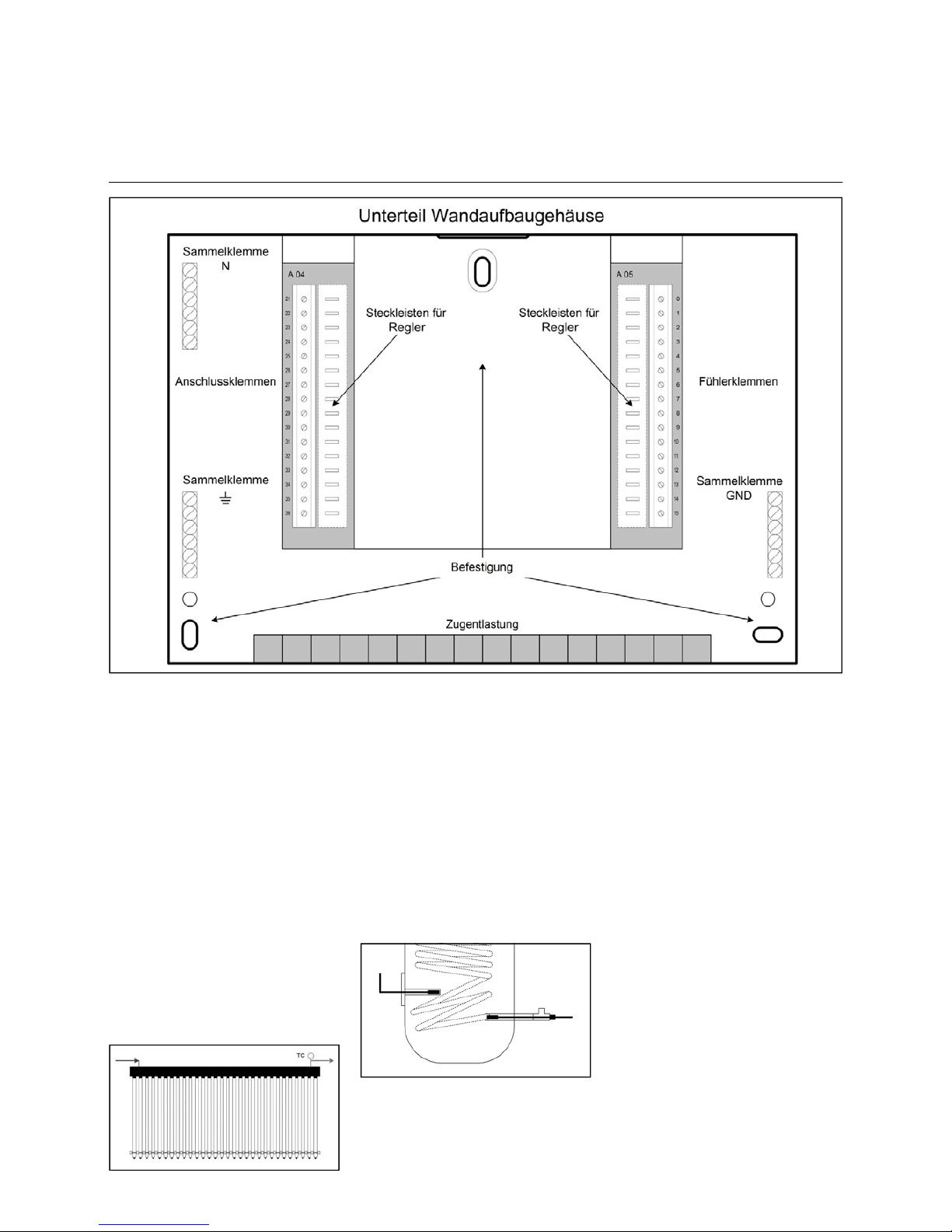
Open up the enclosure. You can
use the bottom part as a template
to locate the mounting holes. Drill 6
mm holes at the marked locations.
Fasten the bottom part of the enclosure to the wall using the anchors
and screws provided. Connect the
sensor, supply and pump wiring to
the terminals as shown in the diagram below.
Mount the controller on the connector provided. You can now refasten
the bottom cover of the enclosure.
Ensure that the electrical wiring is
connected properly and use the
strain relief provision when fastening the wires.
Sensor location
The collector sensors shall be mounted
in the supply connection (hot side) of
the collector.
Some solar system components can
become very hot (risk of burn injuries).
The return-line sensors can be mounted
in the lower part of the storage tank or the
return line from the solar heating system.
Thermowells are installed about halfway
up the storage tank to mount the upper
storage tank sensors.
Page 5
5
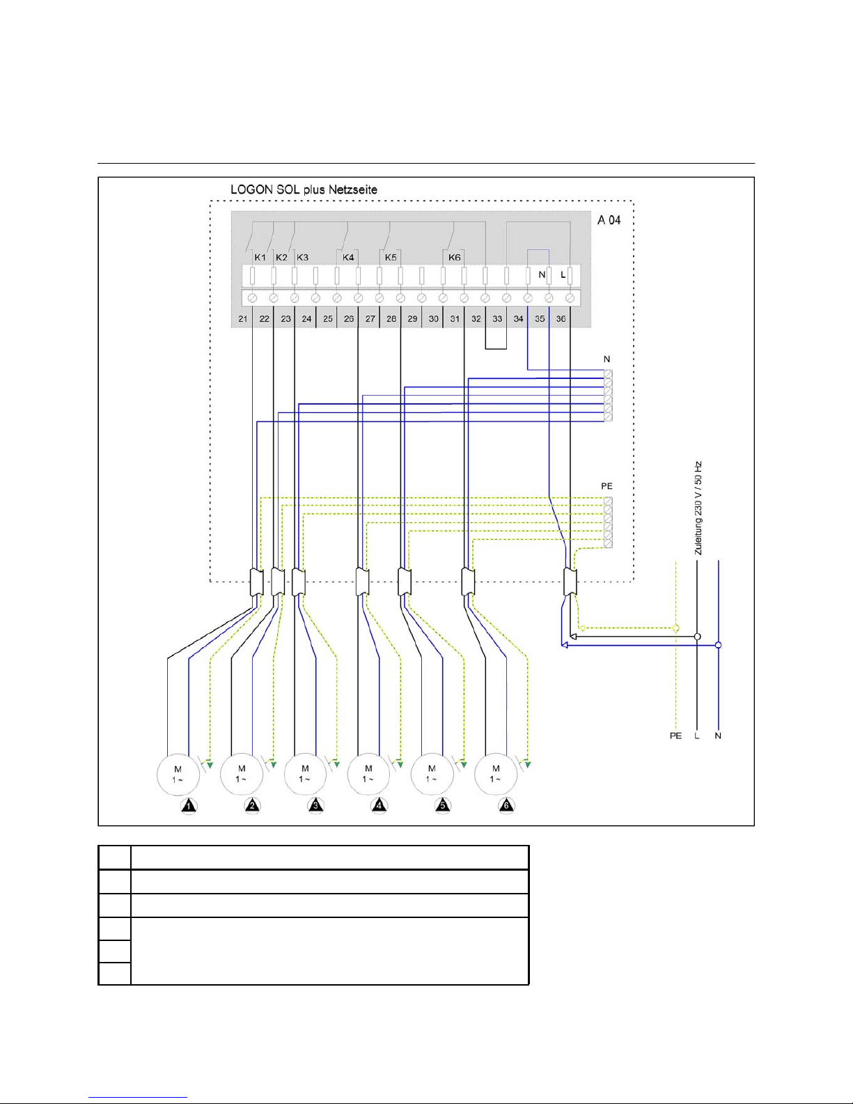
Wiring diagram
LOGON SOL plus
Relay assignment
K1
solar circuit pump 1
K2
solar circuit pump 2 (application dependent)
K3
solar circuit pump 3 (application dependent)
K4
K5
K6
application-specific relay connections
Page 6

6
Wiring diagram
LOGON SOL plus
Sensor assignment
VM
volume flow sensor
S1 TC1
collector temperature, collector panel 1
S2 TC2
collector temperature, collector panel 2
S3 TSP1
upper storage tank temperature, storage tank 1
S4 TSR1
lower storage tank temperature, storage tank 1
S5 TSP2
upper storage tank temperature, storage tank 2
S6 TSR2
lower storage tank temperature, storage tank 2
S7 TSP3
upper storage tank temperature, storage tank 3
S8 TSR3
lower storage tank temperature, storage tank 3
S9 AW
S10 ES
GND
common terminal
application dependent
radiation sensor
Page 7
7
Domestic water backup heating using a boiler
When the LOGON SOL plus
controller is used to control a boiler
that provides supplemental heat for
the domestic water, it must be interconnected with the boiler controller
(sensor-side terminals 14 and 15,
see connection diagram). The following LOGON SOL plus features
make it capable of interacting flexibly with the boiler controller. A
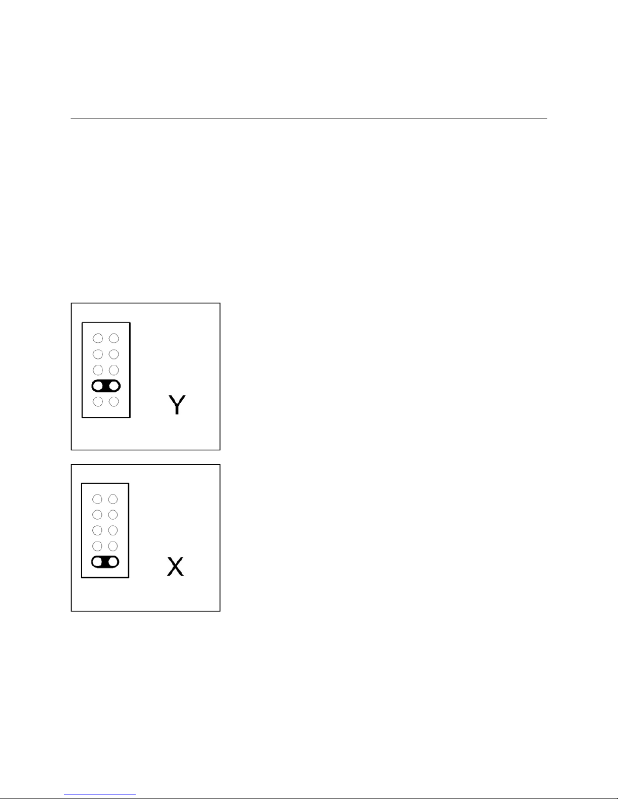
jumper located on the back of the
controller can be used to choose
between a changeover switch with
resistors and a zero-resistance
changeover switch.
Place the jumper in position Y to
use LOGON SOL plus in conjunction with LOGON controllers
(SYSTRON, UNON, VARION) to
control domestic water backup
heating (see diagram).
The connected resistors are used
to simulate temperatures.
Off = 1320 ohms = 70°C
On = 8200 ohms = 25°C
Place the jumper in position X to
use LOGON SOL plus in conjunction with non-LOGON controllers
(THISION, TRIGON, STRATON or
third-party boilers) to control domestic water backup heating. This selects a changeover switch with zero
resistance.
The jumper is in position X when
the controller leaves the factory.
Page 8
After installing the controller, choose the
correct system configuration (number of
collectors/storage tanks) from the system circuit diagrams provided.
The manual shows the wiring for the
required sensors and relays for the
selected circuit schematic.
The respective "Sensor assignment"
tables identify which additional sensor
inputs can be connected.
The respective "Relay assignment"
tables identify which relays are available for additional functions.
The connections and settings for the
most important auxiliary functions are
summarized in the manual. If it becomes necessary to choose settings for
the system that deviate from the factory
settings, the changed values should be
noted in this manual. This will be useful
for later servicing of
the installation.
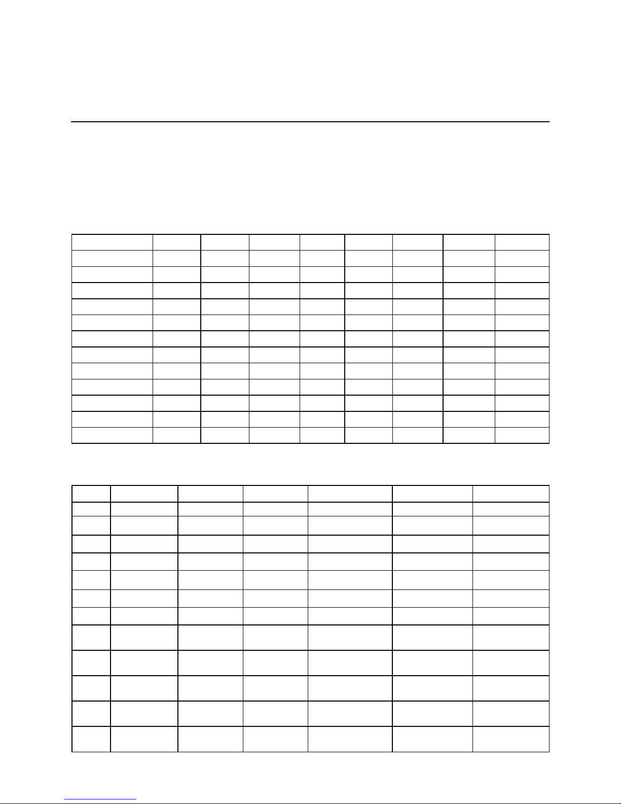
Sensor/Schematic S 1 S 2 S 3 S 4 S 5 S 6 S 7 S 8
1 TC 1 TSP 1 TSR 1
2 TC 1 TSP 1 TSR 1 TSP 2 TSR 2
3 TC 1 TSP 1 TSR 1 TSP 2 TSR 2
4 TC 1 TSP 1 TSR 1 TSP 2 TSR 2
5 TC 1 TSP 1 TSR 1 TSP 2 TSR 2 TSP 3 TSR 3
6 TC 1 TSP 1 TSR 1 TSP 2 TSR 2 TSP 3 TSR 3
7 TC 1 TSP 1 TSR 1 TSP 2 TSR 2 TSP 3 TSR 3
8 TC 1 TC 2 TSP 1 TSR 1
9 TC 1 TC 2 TSP 1 TSR 1 TSP 2 TSR 2
10 TC 1 TC 2 TSP 1 TSR 1 TSP 2 TSR 2 TSP 3 TSR 3
11 TC 1 TC 2 TSP 1 TSR 1 TSP 2 TSR 2
12 TC 1 TC 2 TSP 1 TSR 1 TSP 2 TSR 2 TSP 3 TSR 3
schematic
Relay 1 Relay 2 Relay 3 Relay 4 Relay 5 Rela y 6
1 Solarpumpe
2
solar pump
storage tank 1
solar pump
storage tank 2
3
solar pump transfer heat to storage
tank 2
4
solar pump transfer heat to storage
tank 1
transfer heat to storage
tank 2
5
solar pump
storage tank 1
solar pump
storage tank 2
solar pump
storage tank 3
6
solar pump transfer heat to storage
tanks 2/3
transfer heat to storage
tank 3
7
solar pump transfer heat to storage
tank 1
transfer heat to storage
tank 2
transfer heat to storage
tank 3
8
solar pump
collector 1
solar pump
collector 2
9
solar pump
collector 1
solar pump
collector 2
transfer heat to storage
tank 1
transfer heat to storage
tank 2
10
solar pump
collector 1
solar pump
collector 2
transfer heat to storage
tank 1
transfer heat to storage
tank 2
transfer heat to storage
tank 3
11
solar pump
collector 1
solar pump
collector 2
transfer heat to storage
tank 2
12
solar pump
collector 1
solar pump
collector 2
transfer heat to storage
tanks 2/3
transfer heat to storage
tank 3
The sensors can be freely programmed for special functions (thermostat, temperature comparison, heat gain calculation, solar sensor).
System-dependent sensor assignment
Relay assignment
8
System-dependent sensor assignment
Relay assignment
Page 9

1 pump operation indicator
2 item identifier
3 lower storage tank return temperature
4 upper storage tank temperatures
5 collector temperatures TCI and TC2
6 information
7 "increase" key
8 "decrease" key
12 next
11 time of day
10 timer settings
9 on / off switch
1 2 3 4 5
9 10 11 12
6
7
8
Icons displayed on LCD screen
9
Controller ON / controller OFF
When the controller is switched on,
the display is "normal". The collector
temperature and the upper and lower
storage tank temperature of the (first)
storage tank can be viewed at a glance.
When the controller is turned off, the
display shows "OFF", the time of day
and the day of the week.
The controller can be switched off by
pressing the [On/Off] key for five seconds.
Controller operation
Turning the controller on and off
First collector temperature
Second collector temperature
Upper storage tank temperature
Lower storage tank temperature
Pump ready
Pump on
Backup heating
Alarm
Freeze protection
Page 10

10
In addition, the Info sequence shows
the total heat gain (ERT), the daily heat
gain (ERTd) and the speed of pumps
P1.. P3 (ED1..ED3).
It is preferable to use a volume flow
sensor for the total or daily heat gain
calculation. Parameter VSA = 1 or 2
(E3-4.3) confirms that a volume flow
sensor is being used. The heat gain
display is enabled when confirmation is
received that a volume flow sensor is
present.
If no volume flow sensor is present,
heat gain values can only be displayed if the minimum lower set point
for the heat transfer pump is set to
100 percent. In this situation the heat
gains are calculated on the basis of the
default liquid flow rate.
ERT total heat gain in kWh; range: 0 .. 199999 kWh
Total heat gain can be reset to zero by pressing and holding the [-] key for five seconds while a value is being displayed.
ERTd daily heat gain in kWh; range: 0 .. 999 kWh
The day's heat gain can be reset to zero by pressing and holding the [-] key for five seconds while a value is being displayed.
ED1 speed of pump P1 in %, range 30 .. 100 %
ED2 speed of pump P2 in %, range 30 .. 100 %
ED3 speed of pump P3 in %, range 30 .. 100 %
The speeds (ED1 … ED3) are only displayed if the respective minimum set point (USW1.. USW3) is < 100 %.
Default assignment for measurement inputs (vary with system circuit schematic):
S1 TC1 collector temperature or collector temperature sensor for collector panel 1
S2 TC2 collector temperature or collector temperature sensor for collector panel 2
S3 TSP1 upper storage tank temperature or upper storage tank temperature sensor for storage tank 1
S4 TSR1 lower storage tank temperature or lower storage tank temperature sensor for storage tank 1
S5 TSP2 upper storage tank temperature or upper storage tank temperature sensor for storage tank 2
S6 TSR2 lower storage tank temperature or lower storage tank temperature sensor for storage tank 2
S7 TSP3 upper storage tank temperature or upper storage tank temperature sensor for storage tank 3
S8 TSR3 lower storage tank temperature or lower storage tank temperature sensor for storage tank 3
S9 application dependent
S10 application dependent
collector sensor:
temperature measuring range: -20° .. 150°C, rated temperature range: -20° .. 250°C
storage tank/return-line sensor:
temperature measuring range: -20° .. 150°C, rated temperature range: -20° .. 90°C
The following measured values can be assigned to any measured value input depending on the system configuration or on the activated functions. The measured values - if activated - can be checked using the Info key.
TRH backup heater return-line temperature
TR return-line temperature for heat gain calculation
TX comparative value for heater return-line temperature when backup heating function is activated (e.g., in conjunction
with VISTRON V750 LC.
TW heat exchanger or bypass temperature:
TWW temperature of the first storage tank for hot water destratification
TH1 temperature measurement for first thermostat function:
TH2 temperature measurement for second thermostat function:
TVA1 temperature A for first temperature comparison function:
TVB1 temperature B for first temperature comparison function:
TVA2 temperature A for second temperature comparison function:
TVB2 temperature B for second temperature comparison function:
SE solar sensor to measure impinging solar radiation in W/m2:
VM volume flow measurement or volume flow sensor (GND, VM), measuring range: 50 .. 1500 l/h
VM Volumenstrom-Messwert bzw. Volumenstromsensor (GND, VM), Messbereich: 50 .. 1500 l/h
Page 11

11
Information level
If the appropriate sensors are connected, all relevant storage tank and collector temperatures are
available for display.
Storage tanks can be freely activated or deactivated at the user level. Their status can be displayed
at the information level.
Page 12

12
Information level
TRH
backup heater return-line temperature
Sensor input S9 (fixed) is assigned
via parameter STX (STX set at level
E3 - 1 / 10).
TR
return-line temperature for heat gain
calculation Use parameter STR to assign a sensor input. (Level E3 – 4 / 1)
TX
comparison value for heater return-line
temperature when backup heater function enabled
(e.g., in conjunction with
VISTRON V750LC). Use parameter
STX to assign a sensor input
(parameter 10, E3 – 1 / 10).
TW
heat exchanger or bypass temperature:
A sensor input is automatically assigned when the relevant schematic is
selected (KON, level E 3 -1 / 1).
Page 13

13
Information level
TWW
temperature of the first storage tank for
hot water destratification: Sensor input
S7 is automatically assigned when the
relevant schematic is selected (KON,
E3 -1 / 1).
TSPO
Temperature measurement in the upper part of the storage tank for which
hot water destratification was activated.
TH1
temperature measurement for first thermostat function: Use parameter STH1
to assign a sensor input (parameter 56,
Level E3 – 7/ 1).
TH2
temperature measurement for second
thermostat function: Use parameter
STH2 to assign a sensor input
(parameter 60, E3 – 7 / 5).
Page 14

14
Information level
TVA1
temperature A for first temperature
comparison function: Use parameter
VSA1 to assign a sensor input
(parameter 64, Level E3 – 8 / 1).
TVB1
temperature B for first temperature
comparison function:
Use parameter VSB1 to assign a sensor input (parameter 65, Level E3 – 8 /
2).
TVA2
temperature A for second temperature
comparison function: Use parameter
VSA2 to assign a sensor input
(parameter 69, Level E3 – 8 / 6).
TVB2
temperature B for second temperature
comparison function: Use parameter
VSB2 to assign a sensor input
(parameter 70, Level E3 – 8 / 7).
Page 15

15
Information level
SE
solar sensor to measure impinging solar radiation in W/m2:
The new, modified SE solar sensor can
be connected to any temperature
measurement input, S1 to S10.
Use parameter SSE to assign the input
(parameter 17, E3 – 1 / 17).
VM
volume flow measurement or volume
sensor (terminals: GND, VM), measuring range: 50 .. 1500 l/h
Page 16

16
Information level
In addition, the Info sequence shows
the total heat gain (ERT), the daily heat
gain (ERTd) and the speed of pumps
P1.. P3 (ED1..ED3).
It is preferable to use a volume flow
sensor for the total or daily heat gain
calculation. Parameter VSA = 1 or 2
(E3 - 4 / 3) confirms that a volume flow
sensor is being used. The heat gain
display is enabled when confirmation is
received that a volume flow sensor is
present. If no volume flow sensor is
present, heat gain values can only be
displayed if the minimum lower set
point for the heat transfer pump is set
to 100 percent. In this situation the heat
gains are calculated on the basis of the
default liquid flow rate.
ERTA total heat gain in kWh;
cumulative annual heat gain
range: 0 .. 199999 kWh
Total heat gain can be reset to zero by
pressing and holding the [-] key for five
seconds while a value is being displayed.
ERT0 previous day's heat gain
in kWh;
previous day's heat gain displayed
range: 0 .. 999 kWh
Heat gain can be reset to zero by
pressing and holding the [-] key for five
seconds while a value is being displayed.
ERTd daily heat gain in kWh;
Shows the running total for the day's
heat gain. The total is reset to zero at
12:00 a.m.
range: 0 .. 999 kWh
The day's heat gain can be reset to
zero by pressing and holding the [-] key
for five seconds while a value is being
displayed.
Page 17

17
Information level
Speeds (ED1 … ED3) are only displayed if the respective minimum set
point (USW1.. USW3) is < 100 %.
(parameters 30, 32, 34, level E3 – 2 / 8,
10, 12).
ED1 speed of pump P1 in %, range
30 .. 100 %
ED2 speed of pump P2 in %, range
30 .. 100 %
ED3 speed of pump P3 in %, range
30 .. 100 %
Page 18

18
User level
In addition to operational settings, the
time of day and the timer settings for
the activated timer channels can be set
at the user level. If no functions are
activated by timer channels, the clock
key can only be used to display and set
the time of day.
MAX1
Maximum storage tank heat transfer
temperature for storage tank 1 (upper
heat transfer temperature limit) with
reference to measurement TSP1 when
temperature sensor TSP1 is connected
or with reference to measurement
TSR1 if temperature sensor TSP1 is
not connected.
MAX1
range: 10 .. 90°C;
default setting: MAX1 = 70°C.
MAX2
Maximum storage tank heat transfer
temperature for storage tank 2 (upper
heat transfer temperature limit) with
reference to measurement TSP2 when
temperature sensor TSP2 is connected
or with reference to measurement
TSR2 if temperature sensor TSP2 is
not connected. MAX2 is only displayed
if the system configuration includes
storage tank 2.
MAX2
range: 10 .. 90°C;
default setting: MAX2 = 70°C.
MAX3
Maximum storage tank heat transfer
temperature for storage tank 3 (upper
heat transfer temperature limit) with
reference to measurement TSP3 when
temperature sensor TSP3 is connected
or with reference to measurement
TSR3 if temperature sensor TSP3 is
not connected. MAX3 is only displayed
if the system configuration includes
storage tank 3.
MAX3
range: 10 .. 90°C;
default setting: MAX3 = 70°C.
Navigate to the user level by pressing
the (+) or (-) key. The parameter settings can be changed after pressing the
(+) or (-) key a second time. Press the
enter key to move to the next displayed
value.
Some of the parameters are accessible
from the user level and some from the
professional installer level (level "E3")
User level parameter settings (AE)
Parameter settings that need to be set
by the user are set at the user level. Do
not adjust the user settings until after
the appropriate system circuit schematic has been selected (E3 - 1 No 1),
since all parameters are reset to the
factory default setting when a different
schematic is selected.
Page 19

19
User level
NTH
low temperature set point for backup
heating:
The storage tank low temperature setting that initiates backup heating refers
to the storage tank selected by parameter setting SNH = n (n = 1 .. 3, level E3
– 1 / 7).
It is the temperature that initiates dualsource backup heating with reference
to measurement TSPn (or TSRn if
TSPn is not connected).
Wird die minimale If the temperature
falls below the low temperature setting
during the time the backup heating
SPA1
YES/NO – setting:
Activate or temporarily deactivate storage tank 1.
No 3
Deactivation occurs because the maximum storage tank heat transfer temperature is internally preset to 10°C. This
setting is not affected by the collector
safety function.
SPA1 = YES: storage tank 1 activated
SPA1 = NO: storage tank 1 deactivated
default setting: SPA1 = YES
Parameter SPA1 is disabled for
system configurations 1 and 8.
function is enabled, backup heating is
activated until temperature TSPn (or
TSRn) >= NTH + NHD, or until the enable time has elapsed.
NTH setting range: 10 .. 90°C;
default setting: NTH = 40°C
The backup heating function is assigned to timer channel CH1. Backup
heating enable times are programmed
using CH1. If no times are set, backup
heating is always enabled.
(NHD adjustable at level E3 – 2 / 7)
SPA2
YES/NO – setting:
Activate or temporarily deactivate storage tank 2.
No 4
Deactivation occurs because the maximum storage tank heat transfer temperature is internally preset to 10°C. This
setting is not affected by the collector
safety function.
SPA2 = YES: storage tank 2 activated
SPA2 = NO: storage tank 2 deactivated
default setting: SPA2 = YES
Parameter SPA2 is disabled for
system configurations 1 and 8.
SPA3
YES/NO – setting:
Activate or temporarily deactivate storage tank 3.
No 5
Deactivation occurs because the maximum storage tank heat transfer temperature is internally preset to 10°C. This
setting is not affected by the collector
safety function.
SPA3 = YES: storage tank 3 activated
SPA3 = NO: storage tank 3 deactivated
default setting: SPA3 = YES
Parameter SPA3 is disabled for
system configurations 1,2,3,4,8,9 and
11
Page 20

20
User level
Displaying and setting the day and time
Displaying and setting the date
To set the time of day, press the following controller
keys in sequence:
time -> enter -> Use plus or minus to set the hour. ->
enter -> Use plus or minus to set the minute. ->
enter -> Use plus or minus to set the day. ->
Press the clock key to confirm the changes.
Return to the normal display without saving the changes by pressing the On/Off key.
To set the date, press the following controller keys in sequence:
time -> question mark -> Use plus or minus to set the year. ->
enter -> Use plus or minus to set the day. ->
enter -> Use plus or minus to set the month. ->
Press the clock key to confirm the changes.
Return to the normal display without saving the changes by pressing the On/Off key.
Page 21

21
User level
Timer settings
The controller has a total of 45 timer
settings that can be distributed at will
over 7 channels or can be assigned to
specific functions.
Press the following keys in sequence
to assign switching times for the various timer channels
displays the first active timer channel
Select the first on time setting (I) by pressing the plus or minus key.
Set the hour.
Set the minute.
Set the day
(each day individually or Monday to Sunday).
Use the plus key to set the off time (0).
Continue setting hours, minutes and days as described above.
If you have finished entering timer settings, press the question mark key until
the channel number (e.g., CH1) and
END appear in the display.
The other programmed timer channels
appear next. To skip a timer channel
(because no settings are required),
press the question mark key, then
press the enter key twice. The next
available timer channel appears in the
display. You may now enter the timer
settings as described above.
Channel CH1 (NHZ) backup heating times
Channel CH2 (ANTI) anti-Legionella enable
Channel CH3 (WWU) hot water destratification
Channel CH4 (TH1) first thermostat function
Channel CH5 (TH2) second thermostat function
Channel CH6 (VER1) first differential temperature function
Channel CH7 (VER2)
(CW)
second differential temperature function or collector
monitoring function if CW = 1 (E3-3.6)
Page 22

Notes
Page 23

Notes
Page 24

Service:
ELCO GmbH
D - 64546 Mörfelden-Walldorf
ELCO Austria GmbH
A - 2544 Leobersdorf
ELCOTHERM AG
CH - 7324 Vilters
ELCO-Rendamax B.V.
NL - 1410 AB Naarden
ELCO Belgium n.v./s.a.
B - 1731 Zellik
 Loading...