

Page 1

03/2005 - Art. Nr. 13 018 067A
VECTRON L 03.240 DUO
VECTRON L 03.300 DUO
Betriebsanleitung
Für die autorisierte Fachkraft
Öl-Gebläsebrenner ..............................2-15
Operating instructions
For the authorized specialist
Fuel-oil burners .................................16-29
EN
DE
Ersatzteilliste
Spare parts list
Pièces de rechange
Wisselstukken....................................31-35
Elektro- und Hydraulikschema
Electric and hydraulic diagrams
Schémas électrique et hydraulique
Elektrische en hydraulische schema ...37-39
Page 2

03/2005 - Art. Nr. 13 018 067A
2
Übersicht
Inhaltsverzeichnis
Seite
Übersicht Inhaltsverzeichnis. . . . . . . . . . . . . . . . . . 2
Wichtige Hinweise . . . . . . . . . . . . . . . . . 2
Technische Daten, Arbeitsfeld . . . . . . . . . . . 3
Abmessungen, Brennerbeschreibung . . . . . . . 4
Funktion Betriebs-, Sicherheitsfunktion. . . . . . . . . . . . 5
Feuerungsautomat . . . . . . . . . . . . . . . . . 6
Anschlußoptionen . . . . . . . . . . . . . . . . . 7
Belegungsplan, Anschlußsockel . . . . . . . . . . 8
Montage Brennermontage . . . . . . . . . . . . . . . . . . 9
Elektrische Versorgung . . . . . . . . . . . . . . 10
Ölversorgung . . . . . . . . . . . . . . . . . . . 10
Inbetriebnahme Prüfung vor Inbetriebnahme, Einstelldaten . . . . 11
Luftregulierung, Öldruckregulierung. . . . . . . . 12
Einregulierung des Brenners . . . . . . . . . . . 13
Service Wartung . . . . . . . . . . . . . . . . . . . . . . 14
Störungsbeseitigung . . . . . . . . . . . . . . . 15
Konformitätserklärung
für Ölgebläsebrenner
Wir, CEB
F-74106 ANNEMASSE Cedex
erklären in alleiniger Verantwortung.
daß die Produkte
VECTRON L 03.240 DUO
VECTRON L 03.300 DUO
mit folgenden Normen übereinstimmen
EN 50165
EN 55014
EN 60335
EN 60555-2
EN 60555-3
EN 267
Belgischer königlicher Erlaß vom
08/01/2004
Gemäß den Bestimmungen der
Richtlinien
89 / 392 /EWG Maschinenrichtlinie
89 / 336 /EWG EMV-Richtlinie
73 / 23 /EWG Niederspannungs-
richtlinie
92 / 42 /EWG Wirkungsgrad-
richtlinie
97 / 23 /EWG Druckgeräterichtlinie
werden diese Produkte CE-gekennzeichnet.
Annemasse, den 1. Mai 2003
J.HAEP
Wichtige Hinweise
Die Leichtölbrenner VECTRON
L 03.240 DUO und L 03.300 DUO sind
ausgelegt für die Verbrennung von
Heizöl Extra Leicht nach Ländernormung:
A: ÖNORM C1109: Standard und
schwefelarm
BE: NBN T52.716: Standard und NBN
EN590: schwefelarm
CH: SN 181160-2 : Heizöl EL und
Öko-Heizöl schwefelarm
DE: DIN 51603-1: Standard und
schwefelarm.
Die Brenner entsprechen in Aufbau und
Funktion der EN 267.
Montage, Inbetriebnahme und Wartung
dürfen ausschließlich von autorisierten
Fachkräften ausgeführt werden, wobei
die geltenden Richtlinien und Vorschrif
-
ten zu beachten sind.
Brennerbeschreibung
Der Leichtölbrenner VECTRON
L 03.240/300 DUO ist ein 2-stufiger,
vollautomatisch arbeitender Brenner in
Monoblockausführung. Er eignet sich
innerhalb seines Leistungsbereiches
zur Ausrüstung von Heizkesseln nach
EN 303 bzw. zur Ausrüstung von
Warmlufterzeugern nach DIN 4794 oder
DIN 30697. Jede andere Verwen
dungsart erfordert die Genehmigung von
ELCO.
Lieferumfang
Der Verpackung des Brenners ist
beigelegt:
2 Ölschläuche
1 Anschlußflansch mit Isolationsun
-
terlage
1 Beutel mit Befestigungsteilen
1 Tasche Technische Dokumentation
Für einen sicheren, umweltgerechten
und energiesparenden Betrieb sind
folgende Normen zu berücksichtigen:
DIN 4755
Ölfeuerungen in Heizungsanlagen
EN 226
Anschluß von Ölzerstäubungs- und
Gasbrennern mit Gebläse am Wärmeerzeuger
EN 60335-2
Sicherheit elektrischer Geräte für den
Hausgebrauch
Aufstellungsort
Der Brenner darf nicht in Räumen mit
aggressiven Dämpfen (z.B. Haarspray,
Perchloräthylen, Tetrachlorkohlenstoff),
starkem Staubanfall oder hoher Luft
feuchtigkeit (z.B. Waschküchen) in
Betrieb genommen werden. Eine Zuluft
öffnung muß vorhanden sein, mit :
DE : bis 50kW: 150cm
2
für jedes weitere kW: + 2,0cm
2
CH : bis 33kW : 200 cm²
für jedes weitere kW: + 6,0cm
2
.
Aus kommunalen Vorschriften können
sich Abweichungen ergeben.
Für Schäden, die sich aus folgenden
Gründen ergeben, schließen wir die
Gewährleistung aus:
–
unsachgemäße Verwendung
–
fehlerhafte Montage bzw. Instandset
-
zung durch Käufer oder Dritte, ein
schließlich Einbringen von Teilen
fremder Herkunft.
Übergabe und Bedienungsanwei
-
sung
Der Ersteller der Feuerungsanlage hat
dem Betreiber der Anlage, spätestens
bei der Übergabe, eine Bedienungsund Wartungsanweisung zu übergeben.
Diese ist im Aufstellungsraum des Wär
-
meerzeugers gut sichtbar auszuhän
-
gen. Die Anschrift und Rufnummer der
nächsten Kundendienststelle ist einzu
-
tragen.
Hinweis für den Betreiber
Die Anlage sollte jährlich mindestens
einmal von einer Fachkraft überprüft
werden. Um eine regelmäßige Durch
führung zu gewährleisten, empfiehlt
sich der Abschluß eines Wartungsver
-
trages.
Page 3
03/2005 - Art. Nr. 13 018 067A
3
Übersicht
Technische Daten
Arbeitsfeld
L 03.240 DUO L 03.300 DUO
Brennerleistung min./max. kW 85 - 240 140 - 300
Prüfung - Emissionsklasse Nach EN 267 ; Klasse 2
Öldurchsatz min./max. kg/h 7,2 - 20,2 11,8 - 25,3
Heizöl Heizöl EL nach Ländernormung
Luftklappensteuerung Stellmotor STA 4,5
Regelverhältnis 1 : 1,4 *
Spannung 230 V - 50 Hz
Elektrische Leistungsaufnahme W 200 300
Gewicht ca. kg 23
Elektromotor 2800 min.
-1
160 W
Schutzart IP 21
Feuerungsautomat SH 213
Flammenwächter MZ 770 S
Zündtransformator EBI-M 2 x 7,5 kV
Öldruckpumpe mit Magnetventil BFP 52E L5 70l/h
Schalldruckpegel nach VDI2715 dB(A) 68 71
Max. Umgebungstemperatur 60°C
* Das Regelverhältnis ist ein mittlerer Wert und kann je nach Anlagenauslegung variieren.
Erläuterung zur Typenbezeichnung:
L = Leichtöl
03 = Baugröße
240 = Leistungskennziffer
DUO = Zweistufig
Berechnung der Brennerleistung:
Q
F
= Brennerleistung (kW)
Q
N
= Kesselnennleistung (kW)
hK = Kesselwirkungsgrad (%)
Q
N
QF=
hK
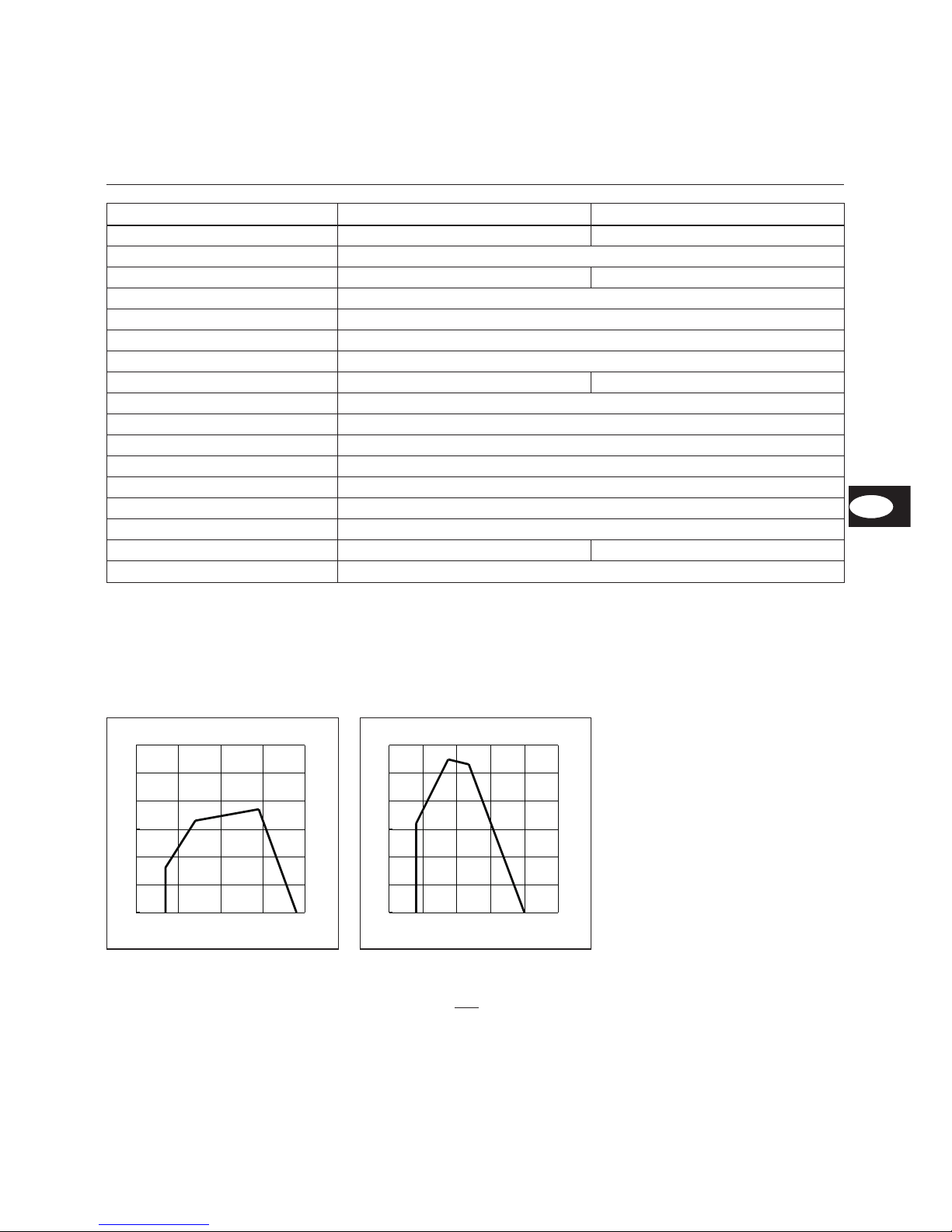
Arbeitsfeld
Die Arbeitsfelder zeigen die Brennerlei
-
stung in Abhängigkeit vom Feuerraum
druck. Sie entsprechen den
Maximalwerten nach EN 267 gemessen
am Prüfflammenrohr.
Bei der Brennerauswahl ist der
Kesselwirkungsgrad zu
berücksichtigen.
daPa mbar
kW
85
240
0
5
10
15
20
25
30
50 100 150 200 250
0
0,5
1
1,5
2
2,5
3
L 03.240 DUO
daPa mbar
kW
140
0
5
10
15
20
25
30
100 150 200 250 300 350
0
0,5
1
1,5
2
2,5
3
L 03.300 DUO
DE
Page 4
03/2005 - Art. Nr. 13 018 067A
4
Übersicht
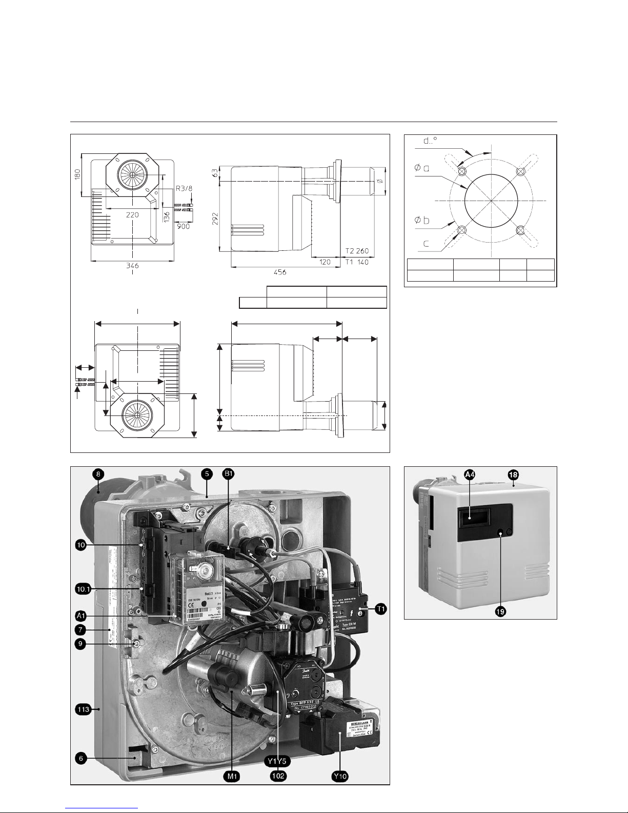
Abmessungen
Brennerbeschreibung
A1 Feuerungsautomat
A4 Transluzente Abdeckung
B1 Flammenwächter
M1 Gebläsemotor und Pumpe
T1 Zündtrafo
Y1 Magnetventil 1. Stufe an Pumpe
Y5 Magnetventil 2. Stufe an Pumpe
Y10 Stellmotor
5 Gehäuse
6 Einhängevorrichtung Geräteplatte
7 Typenschild
8 Flammrohr
9 Halteschrauben der Schläuche
Stromversorgung am Kessel
10 4 polig (Temperaturregler)
10.1 7 polig
18 Haube
19 Entriegelungsknopf
102 Ölpumpe
113 Luftkasten
Ø a (mm) Ø b (mm) c d
125 bis 140 170 bis 184 M8 45°
900
R3/8
220
346
180
136
63
292
456
120
T1: 140
T2: 260
Ø115
L 03.240 DUO L 03.300 DUO
Ø 115 124
Page 5

03/2005 - Art. Nr. 13 018 067A
5
Funktion
Betriebsfunktion
Sicherheitsfunktion
Prinzipschema
1 Zweistufen-Ölbrennerpumpe kpl.
2 Öldruckregler, Vollast
3 Magnetventil, Vollast
4 Öldruckpumpe
5 Öldruckregler, Teillast
6 Magnetventil, Teillast
7 Düsenstange
8 Stauscheibe
9 Flammrohr
10 Brennermotor
11 Luftklappe
12 El. Luftklappenantrieb
Brennerstart
–
Nach Wärmeanforderung durch den
Kesselregler startet der Ölfeuerungs
-
automat den Programmablauf.
–
Gebläsemotor läuft an, Zündung
schaltet ein.
–
Vorbelüftung mit geöffneter Luft
-
klappe (Luftklappe ist nur bei Bren
-
nerstillstand geschlossen).
–
Magnetventil 6 öffnet, Druckregulie
-
rung über Teillastdruckregler 5.
–
Flammenbildung.
–
Zündung schaltet aus.
Brennerbetrieb, Regelung zwischen
Teil- und Vollast
Der Brenner arbeitet mit einer Öldüse und
mit zwei Öldrücken für Teil- und Vollast.
Die Öldrücke werden mit zwei Druck
-
reglern in der Pumpe unabhängig von
einander reguliert. Bei Anforderung
durch den Kesselregler schaltet der
Brenner frühestens nach ca. 13
Sekunden von Teillast auf Vollast.
–
Die Luftklappe 12 wird durch den
Luftklappenantrieb auf Vollastposition
gefahren.
–
Bei einer einstellbaren Luftklappenstellung schließt Magnetventil 3, Teillastdruckregler 5 wird unwirksam,
Vollastdruckregler 2 übernimmt die
Druckregulierung.
–
Luftklappe fährt weiter in Vollastposition, Vollast ist in Betrieb.
Sicherheitsfunktion
Eine Störabschaltung erfolgt:
–
wenn während der Vorbelüftung ein
Flammensignal vorhanden ist
(Fremdlichtüberwachung)
–
wenn beim Start (Brennstofffreigabe)
nach 5s (Sicherheitszeit) keine Flam
-
menbildung erfolgt ist
–
wenn bei Flammenausfall während
des Betriebes nach erfolgloser Pro
grammrepetition keine Flamme
entsteht.
Eine Störabschaltung wird durch Auf
leuchten der Störlampe angezeigt und
kann nach Beseitigung der Störursache
durch Drücken des Entstörknopfes
wieder entriegelt werden.
DE
Page 6

03/2005 - Art. Nr. 13 018 067A
6
Funktion
Feuerungsautomat SH 213
Blink-Code Information / Fehlerursache
x x Wartet auf Freigabe Vorwärmer-Thermostat
x x x Vorbelüftungs-/ Vorzündzeit
x y y y y Kein Flammensignal nach der Sicherheitszeit.
x x y y y Fremdlicht während Vorbelüftungs-/ Vorzündzeit.
x x y y y — y y y y y Manuelle Störabschaltung (siehe auch Verriegelung).
Code
x
y
—
Erläuterung
Kurzes Lichtsignal
Langes Lichtsignal
Pause
Der Ölfeuerungsautomat SH 213 steuert und
überwacht den Gebläsebrenner. Durch den
mikroprozessor-gesteuerten Programmablauf
ergeben sich äußerst stabile Zeiten, unabhängig
von Schwankungen der Netzspannung oder der
Umgebungstemperatur. Der Feuerungsautomat
ist unterspannungssicher ausgelegt. Wenn die
Netzspannung unter dem geforderten Mindest
-
wert liegt, schaltet der Automat ohne ein Fehler
signal ab. Nach Wiedererreichen einer normalen
Spannung läuft der Automat automatisch wieder
an.
Informationssystem
Das eingebaute visuelle Informationssystem
informiert über die Ursachen einer Störabschal
tung. Die jeweils letzte Fehlerursache wird im
Gerät gespeichert und läßt sich auch nach
einem Spannungsausfall beim Wiedereinschal
-
ten des Geräts rekonstruieren. Im Fehlerfall
leuchtet die Leuchtdiode im Entstörknopf R
permanent, bis der Fehler quittiert, d.h. der
Automat entstört wird. Alle 10 Sekunden wird
dieses Leuchten unterbrochen und ein Blink-Code,
der Auskunft über die Störursache gibt, ausge
strahlt.
Über das als Zubehör erhältliche Visualisie
rungsprogramm können dem Automaten
weitere ausführliche Informationen über
Betriebs- und Störvorgänge entnommen
werden.
Verriegelung und Entriegelung
Der Automat kann über den Entstörknopf R verriegelt (in Störung gebracht) und entriegelt
(entstört) werden, sofern am Automat Netzspannung anliegt.
Wird der Knopf im Normalbetrieb oder Anlauf
gedrückt, so geht das Gerät in Störstellung.
Wird der Knopf im Störfall gedrückt, wird der
Automat entriegelt.
m
Vor Ein- oder Ausbau des Automaten
Gerät spannungslos machen. Der
Automat darf nicht geöffnet oder repariert
werden.
Drücken Sie auf R
während ...
… führt zu ...
… weniger als 9
Sekunden...
Entriegelung oder
Verriegelung des
Automaten
… zwischen 9 und
13 Sekunden...
Löschen der
Statistiken des
Automaten
… mehr als 13
Sekunden...
Keine Auswirkung auf
den Automat
Erforderliche Eingangssignale
Ausgangsignale
Temperaturregler Vorwärmer Brennermotor Ölventil Regelung Zündtrafo Flammenwächter Stellmotor SM Störung Entriegelung
1 Einschaltung des Automaten (und des
Vorwärmers)
2 Einschaltung des Brennermotors und Zündtrafos
Stellmotor fährt in Vollastposition
3 Zurückschaltung des Stellmotors auf Teillast
4 Einschaltung des Ölventils
5 Flammenüberprüfung
6 Abschalten des Zündtrafos, Brennerbetrieb
Teillast
7 Brennerbetrieb, Regelung zwischen Teil- und
Vollast
0 Regelabschaltung
10 Störbetrieb
tw Wartezeit Vorwärmer
tlk Öffnungszeit des SM, Vorbelüftung und
Vorzündung
tr Schließzeit des SM
ts Sicherheitszeit
tn Nachzündzeit
tv2 Mindestzeit zwischen Brennstoffventil 1 und 2
Page 7
03/2005 - Art. Nr. 13 018 067A
7
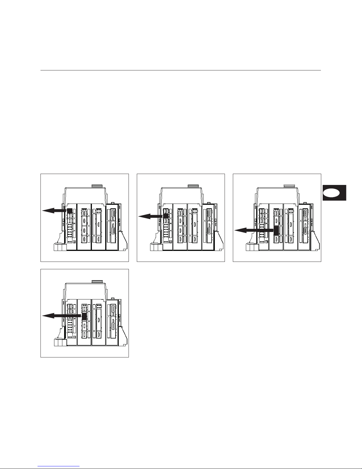
Funktion
Anschlußoptionen
Am Steckersockel unterhalb des Feue
-
rungsautomaten sind diverse Steck
plätze für den Anschluß externer
Geräte (z.B. Betriebsstundenzähler)
vorhanden.
Hierzu :
·
am entsprechenden Steckplatz
Kunststoffabdeckung mit Hilfe eines
kleinen Schraubendrehers
abbrechen.
·
dann Kabel in Richtung Strangaus
-
gang stecken (siehe Bilder).
20
21
10
1/8
4/24
2
11
22
6
5
23
-/4
25
26
20
21
10
1/8
4/24
2
11
22
6
5
23
-/4
25
26
20
21
10
1/8
4/24
2
11
22
6
5
23
-/4
25
26
20
21
10
1/8
4/24
2
11
22
6
5
23
-/4
25
26
Fernentriegelung Störungsleuchte Betriebsstundenzähler
Stromversorgung 230V
DE
Page 8

03/2005 - Art. Nr. 13 018 067A
8
Funktion
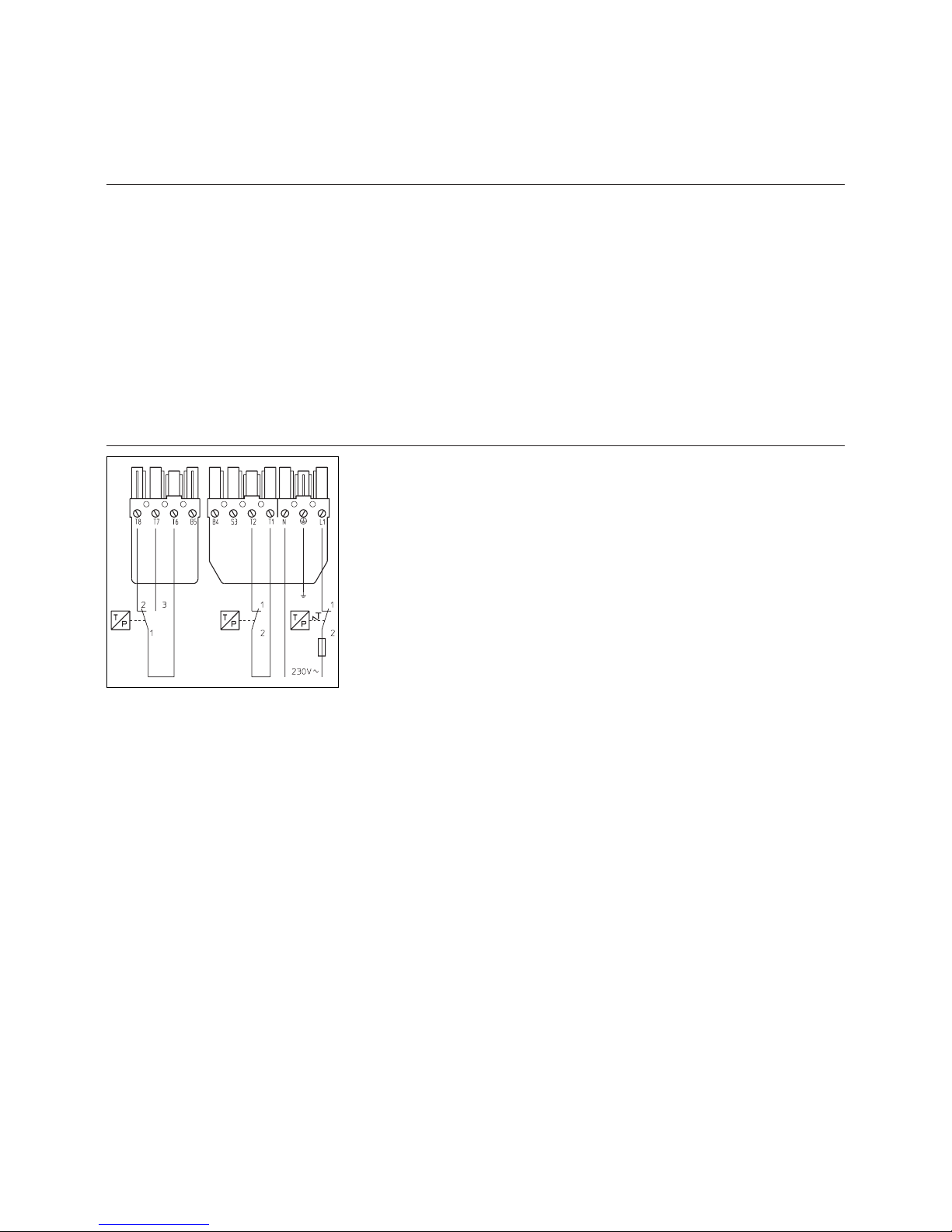
Belegungsplan
Anschlußsockel
20
21
10
1/8
4/24
2
11
22
6
5
23
-/4
25
26
1
2
3
4
7
8
9
10
11
12
18
19
20
15
16
17
18
19
20
22
23
24
25
181918
19
26
27
28
29
30
31
32
33
34
35
36
37
38
39
40
41
42
43
44
45
46
47
48
49
50
51
52
54
55
56
Klemme Bezeichnung Klemme Bezeichnung
1 Klemme A des Automaten 31 Klemme B des Automaten durch Klemmen T6 und T7
(wenn 1. Stufe) am Wiel. St.4P. (1 des SM-Steckers)
2 Klemme 9 des Automaten 32 Klemme C des Automaten (2 des SM-Steckers)
3 Klemme 7 des Automaten 33 Klemme T1 am Wiel. Stecker 7P. (2 des SM-Steckers)
4 Neutral 34 Klemme B5 am Wiel. Stecker 4P. (4 des SM-Steckers) und
Phase der Ventil 2
7 Klemme 5 des Automaten 35 Klemme B4 am Wiel. Stecker 7P. (5 des SM-Steckers) und
Phase der Ventil 1 (Klemme 5 des Automaten)
8 Erde 36 Neutral (6 des SM-Steckers)
9 Neutral 37 Klemme 3 des Automaten
10 Klemme 4 des Automaten 38 Klemme 6 des Automaten (8 des SM-Steckers) (wenn
Brücke zwischen 4 und 6 oder wenn Heizung warm ist,
dann Klemme 4 und 6)
11 Erde 39 Klemme B des Automaten durch Klemmen T6 und T8 am
Wiel. Stecker 4P. (9 des SM-Steckers)
12 Neutral 40 Phase
15 Klemme 1 des Automaten 41 Erde
16 Klemme 2 des Automaten 42 Neutral
17 Klemme 9 des Automaten 43 Klemme 5 des Automaten (Ventil)
18 Klemme B5 am Wiel. Stecker 4P. und Klemme 4 des
SM-Steckers
44 Klemme 6 des Automaten (Heizung)
19 Erde 45 Klemme 4 des Automaten (Heizungskontakt)
20 Neutral 46 Erde
22 Klemme 5 des Automaten und Klemme B4 am
Wiel.Stecker 7P. (Zähler 1. Stufe)
47 Neutral
23 Klemme B5 am Wiel.St. 4P.und Klemme 4 des
SM-Steckers (Zähler 2. Stufe)
48 Klemme T8 am Wiel. Stecker 4P.
24 Neutral 49 Klemme T6 am Wiel. Stecker 4P.
25 Phase 50 Klemme T7 am Wiel. Stecker 4P.
26 Phase 51 Klemme T2 am Wiel. Stecker 7P.
27 Erde 52 Klemme 9 des Automaten
28 Neutral 54 Phase
29 Neutral 55 Erde
30 Klemme 3 des Automaten 56 Neutral
Klemme Stecker Nr Klemme Stecker Nr Stecker Nr Klemme Stecker Nr Klemme
Fernentriegelung
Anzeige
Störung
Luftdruckwächter
Magnetventil I
Brennermotor
FlammenüberprüfungMagnetventil IIBetriebstundenzähler
ZündungStellantrieb
Stromversorgung L1
Dauerbelüftung
Regler
Page 9
9
03/2005 - Art. Nr. 13 018 067A
Montage
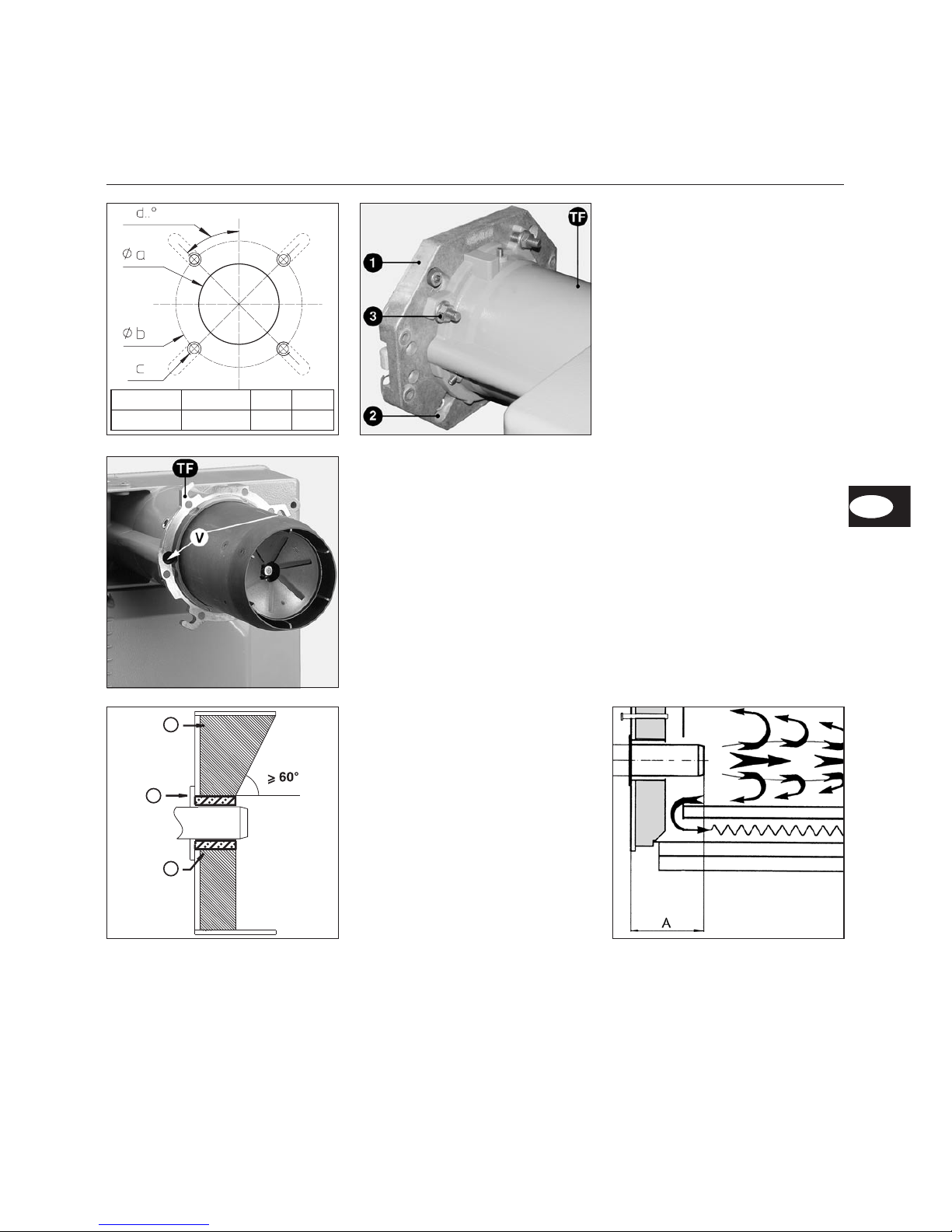
Brennermontage
Montage des Brenners
Der Brennerflansch (Pos.1) ist mit Lang
löchern (Pos.2) ausgestattet und kann
für einen Lochkreis-Ø von 170-184mm
verwendet werden. Die Befestigungs
-
schrauben sind dem Brenner beige
packt. Die Flanschdichtung kann als
Anreißschablone verwendet werden.
Einbau
Brennerflansch (Pos. 1) mit beigelegten
Schrauben am Kessel befestigen.
·
Brenner in den Flansch einführen und
in den Bajonettverschluß drehen
·
3 Befestigungsmuttern (Pos. 3) fest
-
ziehen.
Der Brenner wird normalerweise so
montiert, daß das Lüfterrad unten liegt.
Das Lüfterrad kann jedoch auch nach
oben montiert werden. Zu diesem
Zweck : die beiden Schrauben V lösen,
TF um 180° drehen ; wieder zusammensetzten und die zwei Schrauben V
festziehen.
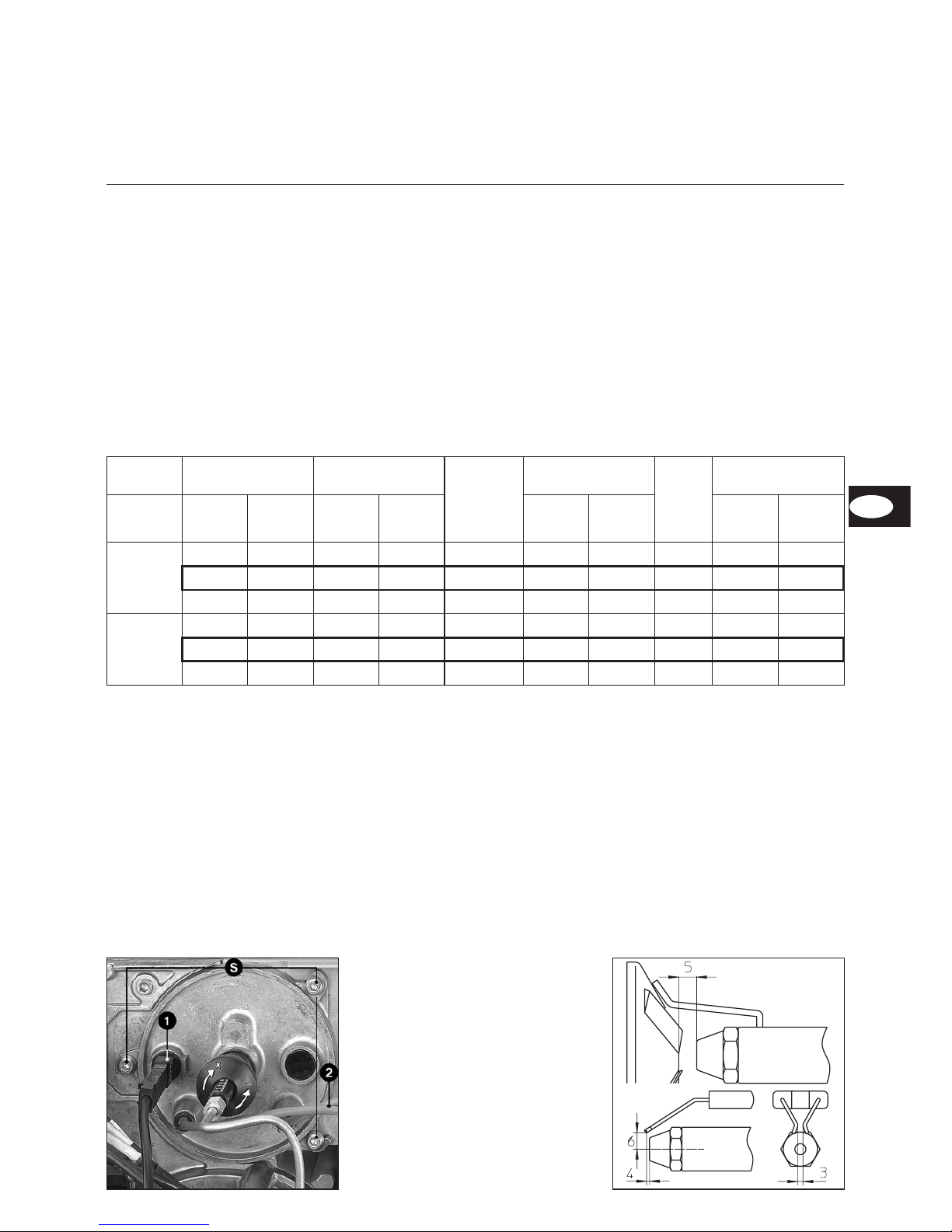
Brennerrohr-Einbautiefe und Aus
-
mauerung
Bei Wärmeerzeugern ohne gekühlte
Vorderwand ist, sofern der Kesselher
-
steller keine andere Angaben macht,
eine Ausmauerung 5 wie im nebenste
-
henden Bild erforderlich. Die Ausmaue
rung darf die Flammrohrvorderkante
nicht überragen und mit maximal 60°
konisch zulaufen. Der Luftspalt zwischen
Ausmauerung und Brennerrohr ist mit
einem elastischen, nicht brennbarem
Isolationsmaterial 6 auszufüllen. Bei
Kesseln mit Umkehrfeuerung ist die
minimale Eintauchtiefe A des Brenner
-
rohres gemäß Angaben des Kesselher
stellers zu beachten.
5
4
6
Ø a (mm) Ø b (mm) c d
125 bis 140
170 bis 184
M8 45°
DE
Page 10
03/2005 - Art. Nr. 13 018 067A
10
Montage
Ölversorgung
Elektrische Versorgung
Die Elektroinstallation und
Anschlußarbeiten werden aus
schließlich vom Elektrofachmann
ausgeführt. Die VDE- und EVU(RGIE- für die Belgien) Vorschriften
und Bestimmungen sind dabei zu
beachten.
Elektrischer Anschluß
· Überprüfen, ob Netzspannung der
angegebenen Betriebsspannung von
230 V, 50 Hz. entspricht
Brennerabsicherung: 10A
Elektrische Steckverbindung
Brenner und Wärmeerzeuger (Kessel)
werden über eine siebenpolige und
eine vierpolige Steckverbindung mitein
ander verbunden.
Das Anschlußkabel wird durch die
Anschlußbride geführt und gesichert.
Ölversorgung
Zu Gewährleistung der Betriebssicher
-
heit der Anlage ist die sorgfältige Instal
lation der Ölversorgung nach DIN 4755,
sowie unter Beachtung örtlicher Vor
schriften erforderlich. Der Brenner ist mit
einer selbstansaugenden Zahnrad
-
pumpe ausgestattet, die als Zweistrang
pumpe über einen Entlüftungsfilter
angeschlossen werden muß.
Beachten :
·
Max. Zulaufdruck an der Pumpe
<2bar.
·
Max. Ansaugvakuum an der Pumpe
<0,4bar
Zur Projektierung und Dimensionierung
von Anlagen mit Sauginstallation für
Heizöl EL ist die ELCO Broschüre
Art.-Nr: 12002182 unbedingt zu
beachten.
·
Mitgelieferte Ölschläuche an der
Ölpumpe anschließen und über
seitliche Öffnung des Gehäuses
führen.
·
Ölfilter mit Entlüftungsfunktion (emp
fohlene Maschenweite : 70 µm) so
plazieren, das ein knickfreier und
zugentlasteter Anschluß der
Ölschläuche gewährleistet ist.
·
Richtigen Anschluß von Vor- und
Rücklauf beachten.
m
Vor Inbetriebnahme Öl mit
Handpumpe ansaugen und
Dichtheit der Ölleitungen überprü
-
fen.
Page 11
03/2005 - Art. Nr. 13 018 067A
11
Inbetriebnahme
Kontrollen vor der Inbetriebnahme
Einstelldaten
Kontrolle der Mischeinrichtung
Obige Einstelldaten sind Grundeinstel
-
lungen. Die Werkseinstelldaten sind
fett umrandet. Mit diesen Einstellungen
kann im Normalfall der Brenner in
Betrieb genommen werden.
Überprüfen Sie in jedem Fall sorgfältig
die Einstellwerte. Es können anlagen
-
bedingte Korrekturen notwendig sein.
Günstige Verbrennungswerte sind unter
Verwendung folgender Düsen zu
erreichen:
Danfoss 45° B
Kontrollen vor der Inbetriebnahme
Vor der Erstinbetriebnahme sind
folgende Punkte zu überprüfen.
·
Korrekte Montage des Brenners
gemäß vorliegender Anleitung.
·
Korrekte Voreinstellung des Brenners
gemäß Angaben Einstelltabelle.
·
Einstellung der Mischeinrichtung,
richtige Düse muß eingesetzt sein.
·
Wärmeerzeuger muß betriebsbereit
montiert sein, die Betriebsvorschrif
ten des Wärmeerzeugers sind zu
beachten.
·
Alle elektrischen Anschlüsse müssen
korrekt ausgeführt sein.
·
Wärmeerzeuger und Heizsystem sind
ausreichend mit Wasser gefüllt,
Umwälzpumpen sind in Betrieb.
·
Temperaturregler, Druckregler, Was
sermangelsicherung und sonstige
evtl. vorhandene Sicherheits-Begren
zungseinrichtungen sind korrekt
angeschlossen und in Betriebsfunk
-
tion.
·
Abgaswege müssen frei sein, Neben
luftvorrichtung, falls vorhanden, in
Funktion.
·
Ausreichende Frischluftzufuhr muß
gewährleistet sein.
·
Wärmeabnahme muß vorhanden sein.
·
Brennstofflagertanks müssen gefüllt
sein.
·
Brennstoffführende Leitungen
müssen fachgerecht montiert, auf
Dichtheit geprüft und entlüftet sein.
·
Normegerechte Messstelle zur
Abgasmessung muß vorhanden sein,
Abgasstrecke bis zur Messstelle muß
dicht sein, so daß Messergebnisse
nicht durch Fremdluft verfälscht
werden.
Brenner Brennerleistung
kW
Heizöldurchsatz
kg/h
Düse
Gph
45°B
Pumpendruck
bar
Maß YmmLuftklappenstellung
1. Stufe 2. Stufe 1. Stufe 2. Stufe 1. Stufe 2. Stufe 1. Stufe 2. Stufe
Nocke IV Nocke I
L 03.240
DUO
85 120 7,2 10,1 1,75 11 22 5 0 20
138 196 11,6 16,5 3,00 11 22 20 20 50
170 240 14,3 20,2 3,75 11 22 30 30 60
L 03.300
DUO
140 200 11,8 16,9 3,00 11 22 15 20 55
172 245 14,5 20,7 3,75 11 22 18 30 80
210 300 17,7 25,3 4,50 11 22 40 35 90
Kontrolle der Mischeinrichtung
Mischeinrichtung ausbauen, hierzu :
·
Düsenzuleitung zwischen Ölpumpe
und Düsengestänge lösen.
·
Fotozelle 1 herausziehen.
·
Zündkabel 2 ausstecken.
·
3 Befestigungsschrauben lösen S.
·
Mischeinrichtung herausziehen.
Mischeinrichtung überprüfen :
·
Düsengrösse überprüfen, ggf. gemäß
obenstehender Tabelle austauschen.
·
Einstellung des Zündelektrodenblocks
und der Stauscheibe überprüfen und
ggf. einstellen.
·
Abstand Düse/Stauscheibe überprü
-
fen und ggf. justieren.
·
Mischeinrichtung wieder einbauen.
DE
Page 12
03/2005 - Art. Nr. 13 018 067A
12
Inbetriebnahme
Luftregulierung
Öldruckregulierung
9
8
5
1
4
2
10
6
7
7
3
1 Druckeinstellung 1. Stufe
2 Druckeinstellung 2. Stufe
3 Sauganschluß G 1/4
4 Rücklaufanschluß G 1/4
5 Anschluß Düsenzuleitung
6 Manometeranschluß Öldruck
7 Druckmeßanschluß Unterdruck
8 Filter Medium
9 Magnetventil 2. Stufe
10 Magnetventil 1. Stufe
Öldruckregulierung
Der Öldruck und damit die Brennerlei
-
stung wird mit dem Öldruckregler 1 für
die Stufe 1 und 2 für die Stufe 2 in der
Pumpe eingestellt. Zur Kontrolle muß
am Manometeranschluß 6 ein
Manometer angesetzt werden,
Gewinde R1/8”.
Drehen nach :
–
rechts : Druckerhöhung
–
links : Druckreduzierung
Unterdruckkontrolle
Das Vakuummeter für die Unterdruck
-
kontrolle ist am Anschluß 7 anzu
schliessen, R1/8". Höchstzulässiger
Unterdruck 0,4 bar. Bei höherem Unter
druck vergast das Heizöl, wodurch
kratzende Geräusche in der Pumpe
entstehen.
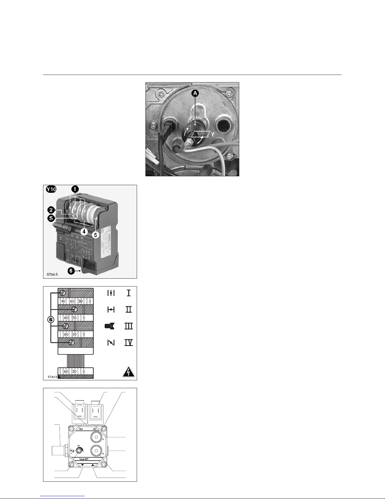
Stellmotor Y10
1 Vier verstellbare rote Nocken
2 Markierung der Nockenstellung
bezogen auf die Skalen 4
S Stellschraube der Nocken
4 Drei zwischen 0 und 160° geteilte
Skalen
5 Zeiger der Luftklappenstellung
6 Abziehbarer Steckverbinder
Funktion der Nocken
I Luftklappenstellung 2. Stufe
II Luftabschluß
III Ansteuerung Magnetventil 2. Stufe
IV Luftklappenstellung 1. Stufe
m
Einstellwert
Schaltnocke III muß zwischen
Schaltnocke I und IV liegen.
Die Luftregulierung im Brennkopf
beeinflußt neben der Luftmenge auch
die Mischzone und den Luftdruck im
Brennerrohr. Drehen der Schraube A
–
nach rechts = mehr Luft
–
nach links = weniger Luft
·
Maß Y entsprechend Einstelltabelle
einstellen.
Die Regulierung der Verbrennungsluft
erfolgt an zwei Stellen :
·
druckseitig über den Öffnungsspalt
zwischen Stauscheibe und Brenner
-
rohr.
·
saugseitig über die durch den Stell
-
motor Y10 angetriebene Luftklappe.
Die saugseitige Luftregulierung erfolgt
über eine Luftklappe.
Diese wird über den Stellmotor Y10
angetrieben.
Die Position der Luftklappe wird durch
Einstellung der Nocken I - IV festgelegt.
Page 13

03/2005 - Art. Nr. 13 018 067A
13
Inbetriebnahme
Einregulierung des Brenners
Brenner starten
Brenner durch Einschalten des Kessel
-
reglers starten. Zur vollständigen Ent
lüftung der Ölleitung während der
Vorbelüftungsphase Entlüftungs
schraube am Ölfilter öffnen. Hierbei
darf ein Unterdruck von 0,4bar nicht
unterschritten werden. Wenn blasen
freies Öl kommt und Filter ganz mit Öl
gefüllt ist, Entlüftungsschraube
schließen.
m
Verpuffungsgefahr !
Während der Einregulierung ständig
CO, CO
2
und Rußemissionen prüfen.
Bei CO-bzw. Rußbildung Verbren
nungswerte optimieren. CO-Anteile
sollten 50ppm nicht überschreiten.
Rußzahl
< 1.
Einstellung Stufe 1 (Nocke IV)
·
Brenner auf 1. Stufe fahren.
·
Über Druckregler 1 Öldruck für Stufe
1 entsprechend gewünschter Bren
nerleistung einstellen. Hierbei ständig
die Verbrennungswerte kontrollieren
(CO, CO
2
, Rußtest). Falls erforderlich
Luftmenge anpassen, ggf. schrittweise vorgehen.
· Luftmenge erhöhen : Nocke IV auf
höheren Skalenwert stellen.
· Brenner kurzzeitig in 2. Stufe
schalten und zurückfahren. Luftklappenmotor nimmt die neue Kleinlastposition.
· Luftmenge reduzieren : Nocke IV
kleineren Skalenwert einstellen, Stellmotor läuft automatisch nach.
Verbrennungswerte optimieren
Ggf. Verbrennungswerte über Einstel
-
lung der Stauscheibenposition (Maß Y)
optimieren.
Hierdurch können Startverhalten,
Pulsation und Verbrennungswerte
beeinflußt werden.
Bei Reduktion des Skalenwertes Y
erhöht sich der CO
2
-Wert, das Startver
halten wird jedoch härter.
Falls erforderlich Luftmengenänderung
durch Anpassung Luftklappenstellung
ausgleichen.
Einstellung Stufe 2 (Nocke I)
·
Mittels 4-poligem Stecker auf 2. Stufe
schalten.
·
Über Druckregler 2 Öldruck für Stufe
2 entsprechend gewünschter Bren
nerleistung einstellen. Hierbei ständig
die Verbrennungswerte kontrollieren
(CO, CO
2
, Rußtest). Falls erforderlich
Luftmenge anpassen, ggf. schrittweise vorgehen.
· Luftmenge erhöhen : Nocke I auf
höheren Skalenwert stellen, Stellmotor läuft automatisch nach.
· Luftmenge reduzieren : Nocke I auf
kleineren Skalenwert stellen.
· Brenner kurzzeitig in 1. Stufe
schalten und wieder hochfahren.
·
Luftklappe fährt auf die neu einge
-
stellte Position.
Achtung : Minimal erforderliche
Abgastemperatur nach Angaben des
Kesselherstellers und nach Anforde
rungen Abgaswege zur Vermeidung
von Kondensation beachten.
Muß das Maß Y bei Einstellung der 1.
Stufe nochmals korrigiert werden, sind
die Einstellwerte der 2. Stufe zu über
-
prüfen.
Einstellung Umschaltpunkt
Magnetventil Stufe 2 (Nocke III)
·
Brenner mehrmals von Stufe 1 auf
Stufe 2 umschalten. Nocke III so ein
stellen, daß ein weicher Übergang
von Stufe 1 auf Stufe 2 gegeben ist.
DE
Page 14
03/2005 - Art. Nr. 13 018 067A
14
Service
Wartung
Servicearbeiten an Kessel und
Brenner führt ausschließlich der
geschulte Heizungsfachmann durch.
Um eine regelmäßige Durchführung
der Servicearbeiten zu gewährleisten
ist dem Betreiber der Anlage der
Abschluß eines Wartungsvertrages
zu empfehlen.
m
·
Vor Wartungs- und Reinigungsarbei
-
ten, Strom abschalten.
·
Originalersatzteile verwenden.
Kontrolle der Verbrennungsorgane
·
Brennerhaube abnehmen.
·
Fotozelle 1 herausnehmen und mit
einem sauberen, trockenen Lappen
abwischen.
·
Zündkabel 2 trafoseitig ausstecken
und Düsenzuleitung lösen.
·
Die drei Deckelschrauben S lösen.
·
Deckel drehen (Bajonettverschluß) und
Mischeinrichtung herausnehmen.
·
Düse austauschen.
·
Zündelektroden und Zündkabel 2
prüfen, ggf. ersetzen.
·
Stauscheibe reinigen.
·
Beim Zusammenbau Einstellungen
kontrollieren.
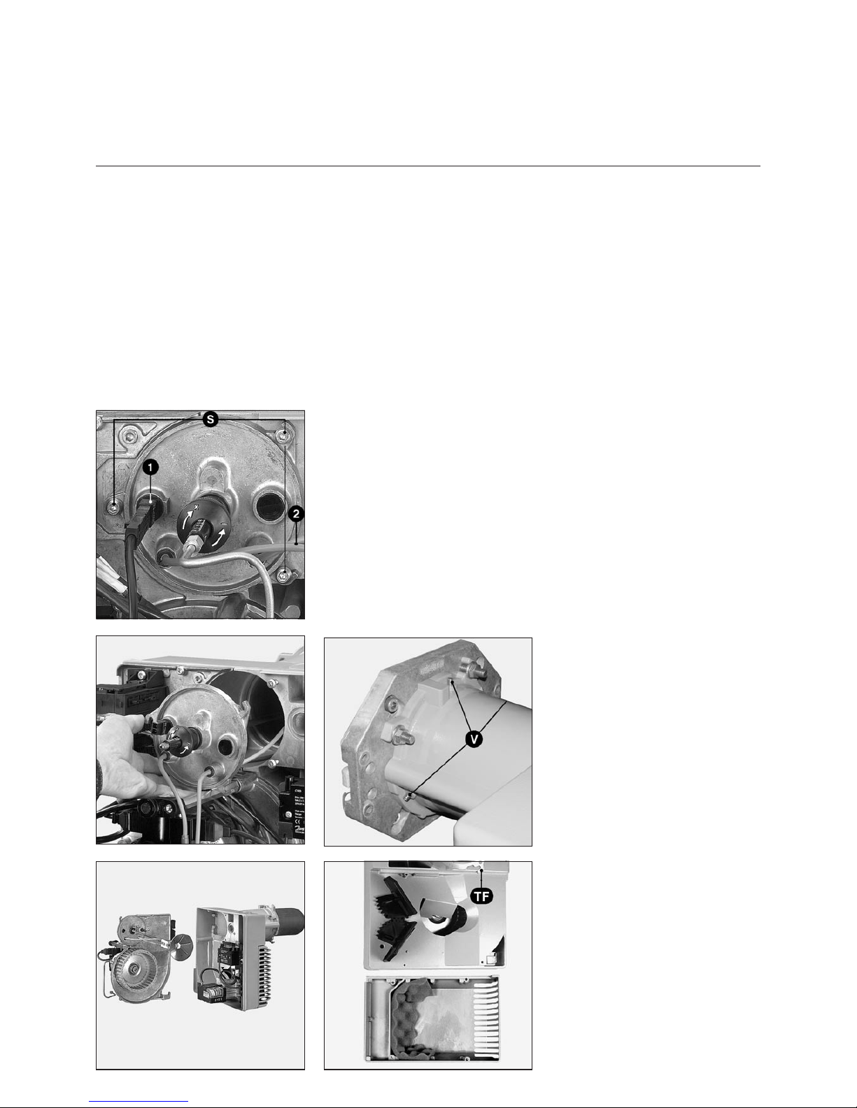
Reinigung des Lüfterrades
·
Die fünf Schrauben der Motorplatte
lösen.
·
Die Geräteplatte ablegen.
·
Luftgehäuse, Lüfterrad von Staub
befreien.
· Anschließend wieder zusammenbauen.
Reinigung des Luftkastens
· Die drei Muttern auf TF lösen.
· Brenner (Bajonett) herausziehen und
am Boden ablegen.
· Die vier Schrauben des Luftkastens
lösen.
· Kasten und Schallisolationsschaum
von Staub befreien.
· Luftkasten wieder montieren.
Auswechseln des Flammrohres
Für diesen Arbeitsgang ist es
notwendig, entweder die Feuerraumtür
zu öffnen oder den Brenner auszu
-
bauen.
–
1) Zugang über die Feuerraumtür :
·
Die drei Schrauben V auf TF lösen.
·
Das Flammrohr nach vorne heraus
-
ziehen.
·
Flammrohr wieder montieren.
·
Zwischenraum zwischen Feuerraum
tür und Flammrohr, falls erforderlich,
mit feuerfestem Material ausfüllen.
–
2) Ausbau des Brenners
·
Die 3 Schrauben V und die drei
Muttern auf TF lösen.
·
Brenner (Bajonett) herausziehen und
am Boden ablegen.
·
Das Flammrohr nach vorne heraus
-
ziehen.
·
Das Flammrohr einbauen und befes
-
tigen.
Reinigung des Pumpenfilters
Der Filter befindet sich im Pumpengehäuse. Er muß bei jeder Wartung
gereinigt werden.
· Ölabsperrhahn schließen.
· Gefäß unter die Pumpe stellen, um
das auslaufende Öl aufzufangen.
· Schrauben und Deckel entfernen.
· Filter herausnehmen, reinigen oder
ersetzen.
· Filter wieder einsetzen, Deckel mit
einer neuen Dichtung wieder
schließen.
·
Gut festschrauben.
·
Ölabsperrhahn wieder öffnen.
·
Druck und Dichtheit überprüfen.
Reinigung der Haube
·
Keine chlorhaltigen oder schleifenden
Mittel benutzen.
·
Haube mit Wasser und einem Reini
-
gungsmittel säubern.
·
Haube wieder montieren.
Hinweise
Nach jedem Eingriff :
·
Unter echten Betriebsbedingungen
(Türen geschlossen, Haube montiert
usw.) die Verbrennung kontrollieren
sowie die einzelnen Leitungen auf
Dichtheit prüfen.
·
Die Ergebnisse in den entsprechen
-
den Unterlagen dokumentieren.
Kontrolle der Abgastemperatur
·
regelmäßig die Abgastemperatur
überprüfen.
·
Kessel reinigen, wenn die Abgastem
peratur den Wert der Inbetriebnahme
um mehr als 30K überschreitet.
·
Setzen Sie zur Vereinfachung der
Kontrolle eine Abgastemperaturan
-
zeige ein.
Page 15

03/2005 - Art. Nr. 13 018 067A
15
Service
Störungsbeseitigung
Ursachen und Beseitigung von
Störungen
Bei Störungen müssen die grundsätzli
-
chen Voraussetzungen zum ordnungs
-
gemäßen Betrieb kontrolliert werden:
1. Ist Strom vorhanden?
2. Ist Öl im Tank?
3. Sind alle Absperrhähne geöffnet?
4. Sind alle Regel- und
Sicherheitsgeräte wie Kesselther
mostat, Wassermangelsicherung,
Endschalter etc. eingestellt?
Kann die Störung nach Kontrolle der
zuvor genannten Punkte nicht beseitigt
werden, überprüfen Sie die mit den
einzelnen Brennerteilen zusammenhän
-
genden Funktionen.
·
Die vom Feuerungsautomat abgege
benen Lichtsignale beachten und ihre
Bedeutung aus nachstehender
Tabelle entnehmen.
Mit dem als Zubehör erhältlichen Visua
lisierungsprogramm
MDE
®
-ELCOSCOPE können dem
Automaten weitere ausführliche Infor
-
mationen über Betriebs- und Störvor
-
gänge entnommen werden.
Sicherheitskomponenten dürfen nicht
repariert, sondern müssen durch Teile
mit derselben Bestellnummer ersetzt
werden.
m
Nur Originalersatzteile
verwenden.
Störung Ursache Beseitigung
Nach Thermostatabschaltung
startet der Brenner nicht mehr.
Automat meldet keine Störung.
Ab- oder Ausfall des Netzspannung
Keine Wärmeanforderung durch
Thermostaten
Störung des Automaten
Ursache für den Netzspannungab- oder
-ausfall feststellen.
Thermostat überprüfen.
Automat ersetzen.
Brenner startet bei Einschaltung
ganz kurz, schaltet ab und gibt
folgendes Signal :
x x y y y - y y y y y
Automat wurde absichtlich verriegelt Automat wieder entriegeln.
Nach Thermostatabschaltung
startet der Brenner nicht mehr und
gibt folgendes Signal :
x x y y y
Fremdlicht bei der Vorbelüftung oder
Vorzündung
Magnetventil ersetzen.
Brenner läuft an, schaltet kurz nach
Einschaltung des Zündtrafos auf
Störung und zeigt folgendes Signal :
x y y y y
Keine Flamme nach Ablauf der
Sicherheitszeit
Ölstand im Tank kontrollieren.
Tank ggf. auffüllen.
Ventile öffnen.
Öldruck und Betrieb der Pumpe,
Kupplung, Filter, Magnetventil
kontrollieren.
Zündkreis, Elektroden und ihre
Einstellungen prüfen. Elektroden
reinigen.
Flammenwächter reinigen oder ersetzen.
Wenn nötig, folgende Teile ersetzen :
Elektroden,
Zündkabel,
Trafo,
Düse.
DE
Page 16

03/2005 - Art. Nr. 13 018 067A
16
Overview
Contents
Page
Summary List of contents . . . . . . . . . . . . . . . . . . 16
Important notes . . . . . . . . . . . . . . . . . . 16
Technical data, power graphs . . . . . . . . . . 17
Dimensions, Burner description . . . . . . . . . 18
Function Operating and safety modes . . . . . . . . . . 19
Automatic control unit . . . . . . . . . . . . . . . 20
Options of connection . . . . . . . . . . . . . . . 21
Layout plant, connection base . . . . . . . . . . 22
Installation Burner assembly . . . . . . . . . . . . . . . . . 23
Electrical supply . . . . . . . . . . . . . . . . . 24
fuel-oil supply . . . . . . . . . . . . . . . . . . . 24
Startup Testing prior to initial use, adjustment settings . . 25
Airflow regulation, fuel-oil-pressure regulation . . 26
Burner adjustment . . . . . . . . . . . . . . . . 27
Servicing Maintenance . . . . . . . . . . . . . . . . . . . 28
Troubleshooting . . . . . . . . . . . . . . . . . . 29
Declaration of conformity for
forced-draught fuel-oil burners
We, CEB, of
F-74106 ANNEMASSE Cedex
declare under our sole responsibility
that the products
VECTRON L 03.240 DUO
VECTRON L 03.300 DUO
conform to the following standards
EN 50165
EN 55014
EN 60335
EN 60555-2
EN 60555-3
EN 267
Belgian Royal Order of 2004/01/08
In accordance with the stipulations of
European Directives
89 / 392 /EEC industrial machines
89 / 336 /EWG EMC-directive
73 / 23 /EEC low-voltage devices
directive
92 / 42 /EEC working efficiency
97 / 23 /EEC pressure equipment
directive
These products bear the CE marking
Annemasse, May 1st 2003
J.HAEP
Important notes
The light-fuel-oil burners VECTRON
L 03.240 DUO and L 03.300 DUO are
designed to run on extra-light fuel-oil
according to countries :
A : ÖNORM C1109: standard or
low-sulphur
BE: NBN T52.716: Fuel oil standard
NBN or EN590: Low-sulphur
CH : SN 181160-2 Extra-Light fuel-oil
and Eco-fuel-oil low sulphur
DE : DIN 51 603-1 standard and
low-sulphur.
The design and function of these
burners both conform to EN 267
standards.
All installation, initial-startup and
maintenance work must be carried out
by authorised service engineers, who
should observe all relevant guidelines,
directives and specifications.
Description of burner
The light-fuel-oil burner VECTRON
L 03.240/300 DUO is a 2-stage,
full-automatic burner in monobloc
configuration. It is suitable, when used
within its operating range, for fitting to
heating boilers conforming to EN 303
standards, and also for the equipping of
warm-air heaters conforming to DIN
4794 or DIN 30697.
For any other use, the agreement of
ELCO must be asked for.
Scope of delivery
The burner is supplied with the following
items:
2 fuel-oil hoses
1 connection flange with Insulating
gasket
1 bag containing installation fittings
1 transparent envelope containing
technical documentation
The following standards should be
observed in order to ensure safe,
environmentally sound and
energy-saving operation:
DIN 4755
Fuel-oil-fired devices installed in
heating systems
EN 226
Connection to heating systems of
vaporizing-fuel-oil and forced-draught
gas burners
EN 60335-2
Safety of electrical devices designed
for domestic use
Place of installation
The burner must not be operated in the
presence of corrosive fumes (e.g.
hairspray, tetrachloroethylene or
carbon tetrachloride), large amounts of
dust, or high levels of air humidity (e.g.
in laundry rooms). Ensure that a
ventilation inlet of the following
characteristics is provided:
DE : up to 50kW: 150cm
2
for each additional kW: + 2,0cm
2
CH : up to 33kW : 200 cm²
for each additional kW: + 6,0cm
2
.
Rules may vary according to local
legislation.
We can accept no warranty liability
whatsoever for loss, damage or
injury caused by any of the
following:
–
Unauthorised use - Incorrect
installation and/or
–
initial startup on the part of the buyer
or any third party, including the fitting
of non-original parts.
Handover and operating instructions
The person engaged to install the firing
system must provide the user with
operation and maintenance instructions
no later than at the moment in which
the unit is handed over for use. These
instructions should be displayed in a
prominent location at the point of
installation of the heating unit, and
should include the address and
telephone number of the nearest
customer service centre.
Advice to the user
Have the system professionally
serviced at least once a year. Its is
recommended to enter into a
maintenance contract in order to
ensure trouble-free running.
Page 17

03/2005 - Art. Nr. 13 018 067A
17
Overview
Technical data
Power graphs
L 03.240 DUO L 03.300 DUO
Burner power min./max. kW 85 - 240 140 - 300
Testing – Emission class as per EN 267 ; class II
Fuel-oil flow rate min./max. kg/h 7.2 - 20.2 11.8 - 25.3
Heating fuel-oil Fue-oil EL conforming to country regulations
Air-flap control system Servomotor STA 4.5
Control ratio 1 : 1.4 *
Voltage 230 V - 50 Hz
Electrical power consumption W 200 300
Weight approx., in kg 23
Electric motor 2800 rpm 160 W
Protection level IP 21
Automatic control unit SH 213
Flame monitor MZ 770 S
Ignition transformer EBI-M 2 x 7,5 kV
Fuel-oil pump with solenoid valve BFP 52E L5 70l/h
Sound level conforms to VDI2715 dB(A) 68 71
Max. ambient temperature 60°C
* The control ratio is a medium value and may change according to installation conditions.
Note on type designation:
L = light fuel-oil
03 = size
240 = power rating
DUO = two-stage
Calculating burner power:
Q
F
= Burner power (kW)
Q
N
= Boiler power rating (kW)
hK = Boiler efficiency rating (%)
Q
N
QF=
hK
Power graphs
Power graphs are expressed as burner
power relative to furnace pressure.
They correspond to the maximum EN
267-compliant values, as measured at
the test combustion chamber.
The efficiency rating of the boiler
should be taken into account when
selecting a burner.
daPa mbar
kW
85
240
0
5
10
15
20
25
30
50 100 150 200 250
0
0,5
1
1,5
2
2,5
3
L 03.240 DUO
daPa mbar
kW
140
0
5
10
15
20
25
30
100 150 200 250 300 350
0
0,5
1
1,5
2
2,5
3
L 03.300 DUO
EN
Page 18

03/2005 - Art. Nr. 13 018 067A
18
Overview
Dimensions
Burner description
A1 Automatic control unit
A4 Translucent cover
B1 Flame monitor
M1 Fan motor and pump
T1 Ignition transformer
Y1 Solenoid valve 1
st
stage on pump
Y5 Solenoid valve 2
nd
stage on pump
Y10 Servomotor
5 Housing
6 Equipment plate hanging device
7 Identification plate
8 Flame tube
9 Fixing screws for hoses
Power supply to the boiler :
10 4-pole (temperature controller)
10.1 7-pole
18 Cover
19 Reset button
102 Fuel-oil pump
113 Air box
Ø a (mm) Ø b (mm) c d
125 to 140 170 to 184 M8 45°
900
R3/8
220
346
180
136
63
292
456
120
T1: 140
T2: 260
Ø115
L 03.240 DUO L 03.300 DUO
Ø 115 124
Page 19

03/2005 - Art. Nr. 13 018 067A
19
Function
Operating mode
Safety mode
Schematic diagram
1 Two-stage fuel-oil pump cpl.
2 Fuel-oil pressure regulator, Full
load
3 Solenoid valve, Full load
4 Fuel-oil pump
5 Fuel-oil-pressure regulator,
Partial load
6 Solenoid valve, Partial load
7 Nozzle line
8 Turbulator
9 Flame tube
10 Burner motor
11 Air flap
12 El. air-flap actuation
Burner start-up
–
Depending on the heat requirement
at the boiler regulator, the automatic
control unit starts up the program
sequence.
–
Fan motor starts up, ignition
sequence activates.
–
Pre-ventilation with opened air flap
(air flap is only closed when burner is
shut down).
–
Solenoid valve 6 opens, pressure
regulation via part-load pressure
regulator 5.
–
Flame begins to burn.
–
Ignition system disconnects.
Burner operation, regulation
between part- and full load
The burner functions with one nozzle
and with two fuel-oil pressures for partand full load. The fuel-oil pressures are
regulated independently of each other
by two pressure regulators in the pump.
When a requirement from the boiler
regulator is detected, the burner
switches over - after no less than 13
seconds.
–
from part- to full load - Air flap 12 is
moved into position by the air-flap
actuating mechanism.
–
On systems fitted with variable
air-flap adjustment, solenoid valve 3
closes, part-load pressure regulator 5
is deactivated, full-load pressure
regulator 2 takes over pressure
regulation.
–
Air flap moves on into full-load
position, full-load is in operation.
Safety function
A safety shutdown is carried out:
–
if a flame indication is present during
pre-ventilation (detection of
unauthorised flame)
–
if no flame is present at startup (fuel
release) after 5 sec. (safety period)
–
if no flame is present after flame
failure during operation, and an
unsuccessful attempt has been made
to repeat the program.
The fault indicator lamp lights up
whenever a safety shutoff has been
carried out. The system can be reset
(once the fault has been remedied) by
pressing the "Release" button.
EN
Page 20

03/2005 - Art. Nr. 13 018 067A
20
Function
Automatic control unit SH 213
Blink-code Information / Cause of malfunction
xx Wait for enable by the pre-heater thermostat
x x x Pre-aeration time/pre-ignition time
x y y y y No flame signal at the end of safety time.
x x y y y If an unauthorised flame is detected during the
pre-ventilation/pre-ignition time.
x x y y y — y y y y y Manual safety shutdown (refer also to locking procedure).
Code
x
y
—
Note
Short light signal
Long light signal
Pause
The SH 213 fuel-oil control unit controls and
monitors the forced-draught burner. The
microprocessor-controlled program sequence
ensures the maximum consistency of the time
periods involved, regardless of fluctuations in the
power-supply voltage or ambient temperature. The
design of the automatic unit protects it from the
effects of brownouts. Whenever the supply voltage
drops below its rated minimum level, the control
unit shuts down - even if no malfunction signal has
been emitted. The control unit switches itself back
on again once the voltage has returned to normal
levels.
Information system
The built-in visual information system keeps you
up-to-date regarding the causes of any safety
shutdown. The most recent cause of a malfunction
is logged, and the information can be reconstructed
on startup of the system - even if there has been a
power failure in the meantime. In the event of a
malfunction occurring, the LED indicator in the
"Reset" button (R) lights up and stays permanently
lit until the fault has been acknowledged (i.e. until
the error has been cleared or the control unit fault
has been dealt with).
The light pauses every ten seconds to emit a
blink-code designed to indicate the cause of the
malfunction. It is possible, using the display
program (available as an accessory), to obtain
further in-depth information on the system's
operating and malfunction procedures.
Locking and unlocking the system
The automatic unit can be locked (corresponding to
a malfunction) and unlocked (cleared) by pressing
the "Reset" button (R), provided the system is
connected to the power supply.
If the button is pressed during normal or startup
mode, the device goes into malfunction mode. If the
button is pressed with the system in malfunction
mode, the automatic unit is unblocked.
m
Always disconnect the power supply before
installing or removing the automatic unit. DO
NOT attempt to open the automatic unit, as
there are no user-serviceable parts inside.
Press R
during ...
... leads to ...
... less than 9
seconds...
Unlocking or
locking of the
control unit
... between 9 and
13 seconds....
Delete the statistics of
the control unit
... More than 13
seconds...
No effect on the
control unit
Required input signals
Output signals
Temperature controller Pre-heater Burner motor Fuel-oil valve Regulation Ignition transformer Flame monitor Servomotor SM Fault Unlocking
1 Activation of automatic unit (and of pre-heater)
2 Activation of burner motor and ignition
transformer servomotor moves to full-load
position
3 Servomotor switches back to partial load
4 Activation of fuel-oil valve
5 Flame check
6 Shutdown of ignition transformer, burner
operation part-load
7 Burner operation, regulation between part and
full load
0 Regulator shutdown
10 Malfunction mode
tw Pre-heater waiting time
tlk Opening time of SM, pre-ventilation and
pre-ignition
tr Shutting time of SM
ts Safety time
tn Post-ignition time
tv2 Minimum time between fuel valve 1 and 2
Page 21

03/2005 - Art. Nr. 13 018 067A
21
Function
Options of connection
Different slots are available for external
devices (e.g. operating-hour counter)
using the sockets underneath the
automatic control unit.
Proceed as follows:
·
Use a small screwdriver to snap off
the plastic cover over the
corresponding plug socket.
·
Insert the cable towards the retainer
outlet (see illustrations).
20
21
10
1/8
4/24
2
11
22
6
5
23
-/4
25
26
20
21
10
1/8
4/24
2
11
22
6
5
23
-/4
25
26
20
21
10
1/8
4/24
2
11
22
6
5
23
-/4
25
26
20
21
10
1/8
4/24
2
11
22
6
5
23
-/4
25
26
Remote reset Fault warning light Operating-hour counter
Power supply 230V
EN
Page 22

03/2005 - Art. Nr. 13 018 067A
22
Function
Layout plant
Connection base
20
21
10
1/8
4/24
2
11
22
6
5
23
-/4
25
26
1
2
3
4
7
8
9
10
11
12
18
19
20
15
16
17
18
19
20
22
23
24
25
181918
19
26
27
28
29
30
31
32
33
34
35
36
37
38
39
40
41
42
43
44
45
46
47
48
49
50
51
52
54
55
56
Terminal Description Terminal Description
1 Terminal A of control unit 31 Terminal B of control unit via terminals T6 and T7 (if
1-stage) at Wiel.-plug. 4P. (1 of SM-plug)
2 Terminal 9 of control unit 32 Terminal C of control unit (2 of SM-plug.)
3 Terminal 7 of control unit 33 Terminal T1 at Wiel.-plug. 7P. (2 of SM-plug)
4 Neutral 34 Terminal B5 at Wiel.-plug 4P. (4 of SM-plug) and phase of
valve 2
7 Terminal 5 of control unit 35 Terminal B4 at Wiel.-plug 7P. (5 of SM-plug) and phase of
valve 1 (terminal 5 of control unit)
8 Earth (ground) 36 Neutral (6 of SM-plug)
9 Neutral 37 Terminal 3 of control unit
10 Terminal 4 of control unit 38 Terminal 6 of control unit (8 of SM-plug) (if bridge between
4 and 6 or if heating system is warm, then terminal 4 und 6)
11 Earth (ground) 39 Terminal B of control unit via terminals T6 and T8 at
Wiel.-plug 4P. (9 of SM-plug)
12 Neutral 40 Phase
15 Terminal 1 of control unit 41 Earth (ground)
16 Terminal 2 of control unit 42 Neutral
17 Terminal 9 of control unit 43 Terminal 5 of control unit (valve)
18 Terminal B5 at Wiel.-plug 4P. and terminal 4 of SM-plug 44 Terminal 6 of control unit (heating)
19 Earth (ground) 45 Terminal 4 of control unit (heating contact)
20 Neutral 46 Earth (ground)
22 Terminal 5 of control unit and terminal B4 at Wiel.-plug 7P.
(Counter 1
st
stage)
47 Neutral
23 Terminal B5 at Wiel.-plug 4P.and terminal 4 of SM-plug
(Counter 2
d
stage)
48 Terminal T8 at Wiel.-plug 4P.
24 Neutral 49 Terminal T6 at Wiel.-plug 4P.
25 Phase 50 Terminal T7 at Wiel.-plug 4P.
26 Phase 51 Terminal T2 at Wiel.-plug 7P.
27 Earth (ground) 52 Terminal 9 of control unit
28 Neutral 54 Phase
29 Neutral 55 Earth (ground)
30 Terminal 3 of control unit 56 Neutral
Terminal Plug no Terminal Plug no Plug no Terminal Plug no Terminal
Remote reset
Malfunction
display
Air-pressure
switch
Solenoid
valve I
Burner motor
Flame checkSolenoid valve IIOperating-hour counter
IgnitionServomotor
Power supply L1
Contin. flow ventilation
Regulator
Page 23

03/2005 - Art. Nr. 13 018 067A
23
Installation
Burner assembly
Fitting the burner
The burner flange 1 is fitted with
elongated slots 2 and can be used for a
hole-circle-Æ of 170-184mm. The fixing
screws are supplied with the burner.
The flange gasket can be used as a
hole template.
Fitting
Attach burner flange 1 to boiler using
the screws supplied.
·
Insert burner into flange and rotate in
twist and lock system.
·
Tighten the 3 fixing nuts 3.
The burner is normally fitted in such a
way that the fan wheel lies at the
bottom. The fan wheel can however
also be fitted pointing upwards. To do
this: loosen the two screws V, rotate TF
by 180°; put back together and tighten
the two screws V.
Burner installation depth and
brickwork
On heaters without a cooled front wall,
unless the boiler manufacturer indicates
otherwise, brickwork 5 as shown in the
illustration is required. The brickwork
must not protrude beyond the leading
edge of the flame tube, and should
have a maximum conical angle of 60°.
The space between the brickwork and
burner should be filled with an elastic,
non-inflammable insulation material 6.
On boilers with reverse firing, minimum
insertion depth A of the burner tube
should be observed as per the
instructions of the boiler manufacturer.
5
4
6
Ø a (mm) Ø b (mm) c d
125 to 140
170 to 184
M8 45°
EN
Page 24

03/2005 - Art. Nr. 13 018 067A
24
Installation
Fuel-oil supply
Electrical supply
All electrical installation and
connection work MUST be carried
out by a suitably qualified service
engineer. VDE and EVU (RGIE for
Belgium) rules and regulations must
be observed when doing so.
Electrical connection
· Check to ensure that the power
supply is as specified (230 V, 50 Hz)
Burner fuse rating: 10A
Electrical plug connection
The electrical plug-and-socket
connection, burner and heat generator
(boiler) are linked via one 7P. and one
4P. plug-and-socket connection.
The connection cable is fed through the
connection clamp and secured.
Fuel-oil supply
Careful installation of the fuel-oil supply
to DIN 4755 standards, along with full
observance of any local rules and
regulations that might apply, is
necessary in order to ensure the safe
operation of the system. The burner is
equipped with a self-priming geared
pump, which should be connected via a
ventilation filter to function as a
two-pipe pump.
Please observe the following points:
·
Max. admission pressure at pump
< 2bar.
·
Max. suction vacuum at pump
< 0,4bar.
For details of project planning and
dimensions of systems with suction
installation for EL heating fuel-oil,
please be sure to refer to ELCO
brochure no: 12002182.
·
Connect the fuel-oil hoses supplied to
the fuel-oil pump and lead in via the
lateral opening in the housing.
·
Locate fuel-oil filter with venting
function (recommended mesh width :
70 µm) in such a way as to ensure
that the fuel-oil hose connections are
not placed under strain or kinked.
·
Observe the correct connection of
infeed and return hoses.
m
Before initial startup, prime the
fuel-oil pump by hand and check
all fuel-oil conduits for leaks.
Page 25

25
03/2005 - Art. Nr. 13 018 067A
Startup
Check settings before startup
Check of the burner head
The above adjustment data correspond
to the default settings. Pre-delivery
adjustment settings appear within a
black rectangle.
These settings allow the burner to be
run in normal operation, but always
carry out a careful check of adjustment
settings, as individual plant conditions
may require certain corrections.
The following nozzles types must be
used to ensure favorable combustion
values:
Danfoss 45° B
Checks before startup.
The following points must be checked
before first use.
·
Correct installation of burner as per
instructions supplied.
·
Correct pre-adjustment of burner as
per data given in table of settings.
·
Adjustment of burner head, the
correct nozzle must be installed. The
heat generator must be installed and
ready for operation, the operating
instructions of the heat generator
should be observed.
·
All electrical connections must be
carried out correctly.
·
Heat generators and heating systems
are to be filled sufficiently with water,
with circulation pumps in operation.
·
Temperature controllers, pressure
regulators, low water-level detectors
and any other safety or limiting
devices that might be fitted are
correctly connected and in operation.
·
Exhaust conduits must be
unobstructed, draught stabilizers - if
fitted - must be functioning.
·
Ensure that there is an adequate
supply of fresh air.
·
The heat dissipation system must
function correctly.
·
Fuel storage tanks must be filled.
·
Fuel conduits must be correctly fitted,
checked for leaks and purged of air.
·
A standard-compliant measuring
point must be available for the
metering of emissions, the exhaust
conduit upstream of this measuring
point must be free of leaks in order to
prevent outside air from causing
measurement errors.
Burner Burner power
kW
Fuel-oil flow rate
kg/h
Nozzle
Gph
45°B
Pump pressure
bar
Dimension Y
mm
Air-flap adjustment
setting
1
st
stage 2dstage 1ststage 2dstage 1ststage 2dstage 1ststage 2dstage
Cam IV Cam I
L 03.240
DUO
85 120 7.2 10.1 1.75 11 22 5 0 20
138 196 11.6 16.5 3.00 11 22 20 20 50
170 240 14.3 20.2 3.75 11 22 30 30 60
L 03.300
DUO
140 200 11.8 16.9 3.00 11 22 15 20 55
172 245 14.5 20.7 3.75 11 22 18 30 80
210 300 17.7 25.3 4.50 11 22 40 35 90
Check of the burner head
Dismantle burner head:
·
Loosen tube between pump and
nozzle line.
·
Pull out photoelectric cell 1.
·
Unplug ignition cable 2.
·
Loosen the three fixing screws S.
·
Pull out burner head.
Check burner head:
·
Check nozzle size, referring - if
necessary - to the above table.
·
Check ignition electrode setting and
turbulator, and adjust as required.
·
Check space between nozzle and
turbulator, and adjust as required.
·
Refit burner head.
EN
Page 26

03/2005 - Art. Nr. 13 018 067A
26
Startup
Adjusting the airflow and fuel-oil pressure
9
8
5
1
4
2
10
6
7
7
3
1 Pressure setting 1ststage
2 Pressure setting 2
nd
stage
3 Suction connection G 1/4
4 Return outlet G 1/4
5 Connection for nozzle tube
6 Pressure-gauge connection
fuel-oil pressure
7 Pressure measurement
connection negative pressure
8 Filter medium
9 Solenoid valve 2
nd
stage
10 Solenoid valve 1
st
stage
Fuel-oil pressure regulation
The fuel-oil pressure, and therefore the
burner power, is adjusted at fuel-oil
pressure regulator 1 for 1
st
stage and at
2 for 2
nd
stage in the pump. Connect a
pressure gauge at point 6 (with R1/8"
thread).
Turn:
–
clockwise to increase pressure,
–
and anticlockwise to decrease
pressure
Checking the negative pressure
The vacuum gauge used for checking
negative pressure (and fitted with an
R1/8" thread) should be attached to
connection 7. Maximum permitted
negative pressure is 0.4 bar. Higher
negative pressure will cause the
heating fuel-oil to turn to gas, leading to
scraping noises in the pump.
Servomotor Y10
1 Four adjustable red cams
2 Marking to indicate cam setting
relative to scale no. 4
S Adjust screws for cams
4 Three scales divided between 0
and 160°
5 Air-flap setting indicator
6 Removable plug-and-socket
connection
Cam function
I Air-flap setting 2
d
stage
II Air shut-off
III Activation of solenoid valve
2
nd
stage
IV Air-flap setting 1
st
stage
m
Setting
Control cam III must lie between
control cam I and IV.
Airflow control in the burner head has
an effect on the air quantity, as well as
on the mixing zone and the air pressure
in the burner tube. Turn adjustment
screw A clockwise to increase airflow,
and anticlockwise to decrease it.
–
clockwise = increased airflow
–
anticlockwise = reduced airflow
·
Adjust dimension Y corresponding to
table of settings.
The combustion air is regulated at two
points:
·
on the pressure side by means of the
opening gap between the turbulator
and the burner tube.
·
On the suction side by means of the
air flap actuated by servomotor Y10.
Suction-side airflow regulation is carried
out using an air flap.
This is actuated by servomotor Y10.
The position of the air flap is
determined by adjusting cams I - IV.
Page 27

03/2005 - Art. Nr. 13 018 067A
27
Startup
Burner adjustment
Start burner
Start burner by activating the boiler regulator.
To purge fully the fuel-oil conduit during
the pre-ventilation phase, open the
bleed screw on the fuel-oil filter. Do not
allow negative pressure to drop below
0.4 bar during this operation. When
fuel-oil begins to flow without bubbles,
and the filter is completely filled with
fuel-oil, shut the bleed screw.
m
Beware of fuel-oil spurting out !
Carry out constant checks for CO,
CO
2
and soot emissions during the
adjustment operation. In the event of
build-ups of CO and/or soot,
optimise the combustion settings.
The proportion of CO must not
exceed 50ppm. Soot-count
<1.
Setting stage 1 (cam IV)
·
Move burner to stage 1.
·
Use pressure regulator 1 to adjust
the fuel-oil pressure for stage 1
according to the desired burner
power. Carry out constant checks on
the combustion air (CO, CO
2
,
soot-test) while doing so. Change the
air quantity if necessary, carrying out
adjustment in small steps.
· To increase the air quantity: move
cam IV to a higher setting on the
scale.
· Move burner shortly to 2
d
stage and
immediately return to 1
st
stage. The
air-flap motor adopts the new
minimum-load position.
· To reduce the air quantity: set cam IV
to a lower scale value, servomotor
adapts position automatically.
Optimise combustion values
Optimise combustion values if
necessary by adjusting the position of
the turbulator (dimension Y).
This can be used to influence starting
performance, pulsations and
combustion values.
Reduction of scale value Y increases
the CO
2
value, making starting
conditions harder.
Adapt the airflow quantity, if necessary,
by adjusting the air flap setting.
Setting stage 2 (cam I)
·
Switch to stage 2 at 4P-plug.
·
Use pressure regulator 2 to adjust
the fuel-oil pressure for stage 2
according to the desired burner
power. Carry out constant checks on
the combustion air (CO, CO
2
,
soot-test) while doing so. Change the
air quantity if necessary, carrying out
adjustment in small steps.
· To increase the air quantity: Set cam
I to a higher scale value, servomotor
adapts position automatically.
· To reduce the air quantity: move cam
I to a lower setting on the scale.
· Move burner shortly to 1
st
stage and
immediately return to 2
d
stage..
· Air flap moves to the newly-adjusted
position.
IMPORTANT: Observe the minimum
required flue-gas temperature, as
per the indications of the boiler
manufacturer, and according to the
requirements of the exhaust gas
conduits, in order to prevent
condensation forming.
If dimension Y needs to be corrected
again when adjusting stage 1, check
the settings of stage 2.
Setting switchover point, solenoid
valve stage 2 (cam III)
·
Switch over burner several times
from stage 1 to stage 2. Adjust cam
III in such a way that there is a
smooth changeover from stage 1 to
stage 2.
EN
Page 28

03/2005 - Art. Nr. 13 018 067A
28
Servicing
Maintenance
All boiler and burner servicing work
should be carried out by an
appropriately trained heating service
specialist. It is recommended to
enter into a maintenance contract in
order to ensure that servicing is
carried out at the intervals
prescribed.
m
·
Shut down power supply BEFORE
carrying out servicing or cleaning
work of any kind.
·
Use only original spare parts.
Check the combustion head
·
Remove burner housing.
·
Remove photoelectric cell 1 and wipe
with a clean, dry cloth.
·
Unplug ignition cable 2 on
transformer side and loosen nozzle
tube.
·
Loosen the three cover screws S.
·
Rotate cover (twist and lock) and
remove burner head.
·
Replace nozzle.
·
Check ignition electrodes and ignition
cable 2, and replace as required.
·
Clean turbulator.
·
Check settings when assembling.
Cleaning the fan wheel
·
Loosen the five screws on the motor
plate.
·
Remove the equipment plate.
·
Check fan housing and fan wheel for
dust and clean as necessary.
· Reassemble.
Cleaning the air box
· Loosen the three nuts on TF.
· Rotate burner (twist and lock) and
place on ground.
· Loosen the four screws on the air
box.
· Clean air box and sound-insulating
foam to remove dust.
· Refit the air box.
Replacement of the flame tube
To carry out this procedure, the
combustion chamber door must be
opened or the burner removed.
–
1) Access via combustion chamber
door:
·
Loosen the three screws V on TF.
·
Remove the flame tube by pulling it
towards the front.
·
Refit the flame tube.
·
Fill the space between the
combustion chamber door and flame
tube with fireproof material, if
necessary.
–
2) Removal of the burner
·
Loosen the three screws V and the
three nuts on TF.
·
Remove the burner (twist and lock)
and place on ground.
·
Remove the flame tube by pulling it
towards the front.
·
Install the flame tube and secure in
place.
Cleaning the pump filter
The filter is located inside the pump
housing. It should be cleaned each time
the system is serviced.
· Close the fuel-oil shutoff valve.
· Place a suitable container under the
pump to collect fuel-oil as it flows out.
· Remove the screws and take off the
cover.
· Remove the filter and clean or replace.
·
Refit filter, reinstall cover with a new
seal and shut tightly.
·
Check that screws are correctly
tightened.
·
Open fuel-oil shutoff valve once more.
·
Check for correct pressure and for
leaks.
Cleaning the cover
·
DO NOT used chlorine-based or
abrasive products.
·
Clean the cover with water and a
suitable cleaning product.
·
Refit the cover.
Precautions
After each intervention:
·
Check combustion performance and
examine the individual conduits for leaks
under real operating conditions (doors
shut, cover fitted, etc.).
·
Note down the results in the
corresponding report forms.
Checking the exhaust-gas
temperature
·
Check the exhaust-gas temperature
at regular intervals.
·
The boiler must be cleaned whenever
the exhaust gas temperature exceeds
the startup setting by more than 30 K.
·
In order to simplify this checking
procedure, fit a flue-gas temperature
gauge.
Page 29

03/2005 - Art. Nr. 13 018 067A
29
Servicing
Troubleshooting
Fault diagnosis and repair
Before carrying out fault diagnosis,
check that the basic requirements for
correct operation are being fulfilled:
1. Is the system connected to the
power supply?
2. Is there fuel-oil in the tank?
3. Are all shutoff valves open?
4. Are all regulating and safety
devices (boiler thermostat, low
water level detector, end-limit
switches, etc.) correctly adjusted?
If the fault cannot be rectified after
checking the above points, check with
the individual burner components
·
Observe the light signals emitted,
interpreting their meaning with the
table shown below.
Use the MDE
®
ELCOSCOPE readout
program (available as an optional
accessory) to obtain further in-depth
information on the control unit's
operating and malfunction procedures.
DO NOT attempt to repair safety
components.
m
Replace them with original
spare parts.
Malfunction Cause Solution
After thermostat shutdown the
burner fails to start.
Automatic unit emits no error
message.
Brownout or power cut.
No demand for heat via thermostat.
Fault in automatic unit.
Determine cause of brownout or power
cut.
Check thermostat.
Replace automatic unit.
Burner starts at switch-on for very
short period, then shuts down and
emits the following signal :
x x y y y - y y y y y
Automatic unit has been locked
intentionally
Reset automatic unit.
After thermostat shutdown the
burner fails to start and emits the
following signal :
x x y y y
Unauthorised flame during pre-ventilation
or pre-ignition
Replace solenoid valve.
Burner starts up, switching shortly
after activation the ignition
transformer to malfunction mode,
emitting the following signal :
x y y y y
No flame at end of safety period Check level of fuel-oil in tank.
Top tank up as required.
Open valves.
Check fuel-oil pressure and pump
operation, coupling, filter, solenoid valve.
Check ignition circuit, electrodes and
their settings.
Electrodes are to be cleaned.
Clean flame-monitoring device, or replace.
Replace the following items as required:
Electrodes,
ignition cable,
transformer,
nozzle.
EN
Page 30

Page 31

31
03/2005 - Art. Nr. 13 018 067A
Ersatzteilliste
Spare parts list
Pièces de rechange
Wisselstukken
VECTRON L 03.240 DUO
VECTRON L 03.300 DUO
L 03.240 DUO T1
3,00 G
13 011 543
L 03.240 DUO T2
3,00 G
13 011 544
L 03.300 DUO T1
3,75 G
13 011 545
L 03.300 DUO T2
3,75 G
13 011 546
Page 32

03/2005 - Art. Nr. 13 018 067A
32
Page 33

3303/2005 - Art. Nr. 13 018 067A
Pos. Désignation Bezeichnung Omschrijving Description Art. Nr. Art. Nr. ELCO
01 Accessoires chaudière Anschlussflansch BG. Bevestigingsset ketel Boiler accessories 13 009 972 13 009 972
02 Joint façade Isolierflansch Dichting Boiler front seal 13 009 973 13 009 973
06 Embout
L 03.240 DUO
Ø100/90/115
x182 T1
x302 T2
L 03.300 DUO
Ø110/90/124/115
x182 T1
x362 T2
Brennerrohr Branderbuis Blast tube
13 009 974
13 009 975
13 009 976
13 009 977
13 009 974
13 009 975
13 009 976
13 009 977
07 Tête de fixation Ø115 Flammenrohraufnahme Bevestiginkop Fixation head 13 011 569 13 011 569
07.1 Vis/embout 3x Schrauben-Set Vijs/branderhuis Screw/blast tube 13 007 804 13 007 804
08 Boîte à air éq. Luftkasten BG Luchtkast Air damper cover Cpl. 13 011 570 13 011 570
13 Volet d’air Luftklappe BG Luchtklep Air flap 13 005 127 13 005 127
14 Servomoteur Berger
STA 4,5
Stellantrieb Servomotor Servomotor 13 007 919 13 007 919
14.1 Accouplement/
servomoteur
Kupplung/
Stellantrieb
Koppeling/
servomotor
Coupling/servomotor 13 009 979 13 009 979
14.2 Prise 9P.+câble/
servomoteur
Stecker+Kabel/
Stellantrieb
Stekker+cable/
servomotor
Plug+cable/servomotor 13 012 227 13 012 227
20 Turbine Ø160x52 Ventilatorrad Ventilator Air fan 13 010 095 13 005 240
21 Moteur + condensateur
160W
Motor + Kondensator + Kupplung Motor + condensator Motor + Capacitor 13 009 981 121.843.2828
21.1 Prise C.3P.+câble/
moteur
Stecker+Kabel/Motor Stekker+cable/motor Plug+cable/motor 13 011 089 13 011 089
22 Condensateur 5µF, 400V Kondensator 5µF Condensator 5µF Capacitor 5µF 13 009 983 13 001 698
23 Pompe
BFP 52E
Pumpe
BFP 52E
Pomp
BFP 52E
Pump
BFP 52E
13 012 438 13 012 438
23.1 Câble vanne fuel 2e all. Kabel m. Stecker / Ventil 2 St. Kabel met st. / ventiel 2.trap Cable with plug / Valve (2
nd
stage) 13 011 091 13 011 091
23.2 Câble vanne fuel 1e all. Kabel m. Stecker / Ventil 1 St. Kabel met st. / ventiel 1.trap Cable with plug / Valve (1
st
stage) 13 011 090 13 011 090
24 Accouplement pompe/moteur Kupplung Pumpe/Motor Koppeling pomp/motor Coupling pump/motor 13 009 985 13 000 385
25 Bobines NC Magnetspule NC Bobijn NC Magnet coil NC 13 012 581 13 012 581
26 Bobines NO Magnetspule NO Bobijn NO Magnet coil NO 13 012 586 13 012 586
27 Filtre + joint Filtereinsatz + dichtung-Set Filter voor pomp Filter inlet 13 012 580 13 012 580 }
41 Coffret fuel SH213 Feuerungsautomat SH213 Branderautomat SH213 Control unit SH213 13 011 049 13 011 049
42 Cassette de raccordement Anschlu8kasten m.
Relaissockel O.Kabel
Steckerbusbanhof Elec. Connection box 13 011 050 13 011 050
43 Kit bouton de réarmenent Taster Entriegelung Terugstelknop Reset button 13 011 087 13 011 087
43.1 Câble bouton de réarmenent Kabel m. Stecker /
Entriegelung
Kabel met st. /Terugstelknop Cable with plug / Unlocking 13 011 088 13 011 088
44 Cellule MZ 770 S Fotozelle MZ 770 S Fotocel MZ 770 S Photocell MZ 770 S 13 009 774 175.855.9799
44.1 Prise D.2P.+câble/
cellule
Stecker+Kabel/
Fotozelle
Stekker+cable/
Fotocel
Plug+cable/Photocell 13 011 093 13 011 093
Page 34

34 03/2005 - Art. Nr. 13 018 067A
Pos. Désignation Bezeichnung Omschrijving Description Art. Nr. Art. Nr. ELCO
50 Tête de combustion
L 03.240 DUO
T1
T2
L 03.300 DUO
T1
T2
Brennerkopf BG Brander kop Burner head cpl.
13 011 633
13 011 634
13 009 001
13 009 000
13 011 633
13 011 634
13 009 001
13 009 000
51 Déflecteur
L 03.240DUO
Ø90/20-6FD.
L 03.300DUO
Ø90/20-6FD.+col.cre
Turbulator Vlammenhaker Turbulator
13 009 987
13 009 988
161.843.2851
161.868.5763
}
}
52 Electrode allu.
(bloc blanc)
Blockelektrode Elektrode ontst. Ignition electrode 13 007 907 172.843.6568 }
52.1 Câble allumage
L500 T1 2x
L625 T2 2x
Zündkabel Ontstekingskabel Ignition lead
13 009 989
13 009 990
13 009 989
13 009 990
53 Ligne gicleur
L426 T1
L526 T2
Düsengestänge Sproeierlijn Nozzle assembly
13 009 991
13 009 992
13 009 991
13 009 992
57 Passe fil Ø5/9 2x Kabeldurchführung Geleider Ø5/9 Funnel Ø5/9 13 007 808 13 003 695
58 Bouton de réglage Regulierung Knopf-Set Afstell Setting knob 13 007 852 13 007 852
60 Transformateur allu. EBI-M
2x7,5kV
Zündtrafo Transformator Ignition transfo. 13 009 663 13 009 663
60.1 Prise C.2P.+câble/
transfo.
Kabel m. Stecker/
Zündtrafo
Stekker+cable/
Transformator
Plug+cable/
Ignition transfo.
13 012 226 13 012 226
62 Vis/capot Schraube/Haube Vijs/branderkap Screw/ 13 007 853 13 007 853
65 Tube Po./ligne gicleur Düsenzuleitung Buisje pomp Fuel-oil feed tube 13 012 437 13 012 437
67 Flexible L1,50 m 2x Ölschlauch L1,50 m Olieslang L1,50 m Fuel-oil hose L1,50 m 13 007 940 13 004 831
68 Capot gris Graue Haube Kap Grey cover 13 00 13 00
68.1 Plaquette frontale Beschriftungsplatte Frontplaat standaard Standard front cover 13 0 13 0
70 Gicleur Danfoss Düse Danfoss Sproeier Danfoss Nozzle Danfoss
1,75 45° S A 088 888 145.832.8905 }
3,00 45° B A 089 201 145.829.2420 }
3,75 45° B A 089 202 3333 120 654 }
4,50 45° B A 089 203 3333 120 408 }
Page 35

03/2005 - Art. Nr. 13 018 067A
35
Légende Legende Legende Caption
| Pièces
d’entretien
Hilfsmaterial Onderhoudsonder-
delen
Maintains parts
Pièces de
rechange
Ersatzteile Wisselstukken Spare parts
} Pièces d’usure Verschleissteile Slijtage-onderdelen Wearing parts
DE
|
Hilfsmittel sind solche Teile, die im Zuge der Wartung beim Zusammenbau demontierter Teile
vorsorglich ersetzt werden sollten, z.B Dichtungsmaterial.
Für Verschleißteile und Hilfsmittel gilt die Haltbarkeitsgarantie gemäß den Geschäftsbedingungen der
Firma ELCO nicht.
}
Verschleißteile sind solche Teile, die auch bei bestimmungsgemäßem Gebrauch des Gesamtproduktes
im Rahmen der Lebensdauer des Produktes mehrfach ausgetauscht werden müssen (z.B. Öldüsen,
Ölfilter).
Für Verschleißteile und Hilfsmittel gilt die Haltbarkeitsgarantie gemäß den Geschäftsbedingungen der
Firma ELCO nicht.
|
Maintenance parts are parts which should be replaced on a preventive basis during maintenance when
reassembling disassembled parts (sealing components for example)..
For wear parts and maintenance parts, ELCO’s performance warranty for them over time under
commercial conditions does not apply.
}
Wear parts are parts that have to be replaced several times during the product’s service life, even when
use of the overall product is in line with its intended purpose (for example oil injectors and oil filters).
For wear parts and maintenance parts, ELCO’s performance warranty for them over time under
commercial conditions does not apply.
|
Les pièces d’entretien sont des pièces qui devraient être remplacées à titre préventif au cours de
l’entretien lors du remontage des pièces démontées, par exemple des éléments d’étanchéité.
Pour les pièces d’usure et les pièces d’entretien, la garantie de tenue dans le temps selon les conditions
commerciales de la société ELCO ne s’applique pas.
}
Les pièces d’usure sont des pièces qui doivent être remplacées à plusieurs reprises au cours de la
durée de vie du produit, même dans le cas d’une utilisation du produit global conforme à sa destination
(par exemple les injecteurs d’huile, les filtres d’huile).
Pour les pièces d’usure et les pièces d’entretien, la garantie de tenue dans le temps selon les conditions
commerciales de la société ELCO ne s’applique pas.
|
Onderhoudsonderdelen zijn onderdelen die horen te worden vervangen als preventieve maatregel bij
onderhoudsbeurten, telkens wanneer onderdelen worden gedemonteerd, bijvoorbeeld
afdichtingselementen.
Voor slijtage- en onderhoudsonderdelen is de garantie van levensduur volgens de handelsvoorwaarden
van ELCO niet van kracht.
}
Slijtage-onderdelen zijn onderdelen die meermaals gedurende de levensduur van het product moeten
worden vervangen, ook als het gehele product conform de bestemming ervan wordt gebruikt (zulke
onderdelen zijn bijvoorbeeld olie-injectoren, oliefilters).
Voor slijtage- en onderhoudsonderdelen is de garantie van levensduur volgens de handelsvoorwaarden
van ELCO niet van kracht.
EN
FR
NL
Page 36

03/2005 - Art. Nr. 13 018 067A
36
Page 37

37
03/2005 - Art. Nr. 13 018 067A
Elektro- und Hydraulikschema
Electric and hydraulic diagrams
Schémas électrique et hydraulique
Elektrische en hydraulische schema
VECTRON L 03.240 DUO
VECTRON L 03.300 DUO
L 03.240 DUO T1
3,00 G
13 011 543
L 03.240 DUO T2
3,00 G
13 011 544
L 03.300 DUO T1
3,75 G
13 011 545
L 03.300 DUO T2
3,75 G
13 011 546
Page 38

1
2 3 4 5 6 7 8
NPE
L1
T2
T1
Q1
1
2
3
4
10 A
F1
1
2
T
P
S6
1
2
T
P
S7
P
1
2
T
P
T7T8T6B5
P2
h
B4
P1
h
S3
H6
x1
x2
Y10
M
6 8 2 3
1
A B
B
A
4 597
3N23
PTC
B
AA
36 37 38 32 39
31
10
12
.. .
M1
PE
U
V
1~
M
11
20
18
..
Y2
1
2
19
.
9 7
..
Y1
1
2
.
8
1516
..
B3
4 23
1
S1
13
14
T2
.
30
42
41
40
29
.
33 34 35
21
22
X1S
X1B
230V 50Hz
N
L1
Kessel /
Chaudière /
/ Ketel
Alimentation
Einspeisung
Power supply
Elektrische
voeding
Boiler
Sicherheitsbegrenzer
Th./pr. sécurité
Safety limiter
Limiteur
Begrenzer
Limiter
Beperkingsthermostaat
X2S
X2B
Running hours meter
Betriebstundenzaehler
Compteurs horaires
OPTIONOPTION
Panne
Störung
Trouble
OPTION
Uurteller
Storing
Mise à la terre conformément au réseau local!
Erdung nach örtlichen Vorschriften!
Earthing in accordance with local regulation!
Aarding in overeenstemming met her
plaatselijk net
Der Schutz der Anlage muß
den geltenden Normen entsprechen.
aux normes en vigueur.
Protection de l'installation conforme
Protection of the installation in
conformity with the actual norms.
in overeenstemming volgens die van
Bescherming van de installatie moet
kracht zijn.
2 allures
2-stufig
2-stages
2-trap
A5
A1
SH 2XX
Brenner
Brûleur
Burner
Brander
Prinzip-
darstellung
Schéma
de principe
Basic circuit
diagram
Principeschema
Beveiligingsthermostaat
23
4/24
2
1/8
11
21
20
5
-/4
OPTION
Durchl. Belüftung
Ventil. perm.
Continuous ventil.
Voortdurende ventil.
A
B
C
F
E
D
Am :
9735
Visa :
13011810.A
Mtz
Art. N°:
N° de schéma :
2
/
1
Page :
L03.1.0213
Date :
17.09.02
Page 39

1
2 3 4 5 6 7 8
M
M
Brennermotor
M1
B3
Feuerungsautomat
Anschlußkasten
A1
A5
Flammenwächter
106
102
Oel
Fuel
Oil
118
Y2
104
Y1
M1
T2
101
113
103
Y10
104
105
Air
Lucht
Luft
Air
Olie
Oelventil
Stufe 1
Oelventil
Stufe 2
Stellantrieb
Y1
Y2
Y10
Zündtrafo.
T2
S1
Störlicht/Entriege-
lungsknopf
Burner motor
Connection
cartridge
Bedienings en
veiligheidskoffer
Control and safety
unit
Verbindingsdoos
Fotocel
Cell
Moteur du
brûleur
Coffret de
contrôle
Cassette de
raccordement
Cellule
Brandermotor
Oil valve
stage 1
Oil valve
stage 2
Damper motor
Ignition
transformer
Ontstekings-
transformator
Vanne fuel
2° allure
Servomoteur
Vanne fuel
1° allure
Transformateur
d'allumage
Oliemagnetventiel
1. trap
Oliemagnetventiel
2. trap
Servomotor
Voyant défaut/
réarmement
Druckregler
Schlauch
Filter
Düse
Ansauggitter
Flexible
Filtre
Gicleur
Grille
d'aspiration
Régulateur de
pression
Hose
Filter
Nozzle
Pressure regulator
Soepele leiding
Sproier
Druckregelaar
105
106
104
113
118
Ventilator
Pumpe
Luftklappe
Ventilateur
Pompe
Volet d'air
Blower
Pump
Air flap
Ventilator
Pomp
Luchtklep
101
102
103
Filter
Air intake
protection
Luchthuis
Fault indicator/
release button
Foutlamp/
resetknop
A
B
C
F
E
D
Am :
9735
Visa :
13011810.A
Mtz
Art. N°:
N° de schéma :
2
/
2
Page :
L03.1.0213
Date :
17.09.02
Page 40

Page 41

41
03/2005 - Art. Nr. 13 018 067A
Page 42

03/2005 - Art. Nr. 13 018 067A
42
Page 43

43
03/2005 - Art. Nr. 13 018 067A
Page 44

03/2005 - Art. Nr. 13 018 067A
44
Fabriqué en EU. Made in EU. Hergestellt in der EU. Gefabriceerd in de EU
Document non contractuel. Non contractual document. Angaben ohne Gewähr.
Niet-contractueel document
AT
BE
CH
DE
FR
Adresse Service-Hotline
ELCO Austria GmbH
Aredstr.16-18
2544 Leobersdorf
0810-400010
ELCO Belgium n.v./s.a.
Pontbeeklaan-53
1731 Zellik
02-4631902
ELCOTHERM AG
Sarganserstrasse 100
7324 Vilters
0848 808 808
ELCO Deutschland GmbH
Dreieichstr.10
64546 Mörfelden-Walldorf
0180-3526180
ELCO France
18 rue des Buchillons
74106 Annemasse
0450877624
ELCO-Rendamax B.V.
Amsterdamsestraatweg 27
1410 AB Naarden
035-6957350
NL
 Loading...