

Page 1
05/2009 - Art. Nr. 4200 1017 4400A
Operating instructions
For the authorized specialist
Gas burners ........................................... 2-20
Betriebsanleitung
Für die autorisierte Fachkraft
Gasgebläsebrenner............................. 21-39
Инструкция по эксплутации
Для авторизованного специалиста
газовые горелки................................. 40-58
ES08.5200 G/F-VT
fr, it, es................................. 4200 1017 4300
en
de
ru
............................................. 4200 1017 4200
Page 2

05/2009 - Art. Nr. 4200 1017 4400A2
General information
Contents
Guarantee/safety
Main statutory instruments
Contents
General information
Guarantee, safety............................... 2
Main statutory instruments................. 2
Overview, key.....................................3
Packaging...........................................4
Technical data
See technical data
No. 4200 1017 4200
Installation
Assembly............................................5
Gas connection ..................................6
Electrical connection .......................... 6
Commissioning
Preliminary checks 7
Settings .....................................7 to 13
Programming the control
and safety unit.........................14 to 15
TC control panel...............................16
Firing ................................................17
Setting and checking of safety
devices .............................................17
Maintenance....................................18
Troubleshooting ............................. 19
Guarantee
Installation and start-up must be carried
out in accordance with correct practice
by a qualified specialist.
Current regulations, as well as the
following instructions, must be complied
with. Any failure, however minor, to
observe these provisions shall absolve
the manufacturer from any liability. Also
see:
- guarantee certificate enclosed with
burner,
- general terms of sale.
Safety
The burner is designed to be installed on
a generator connected to exhaust pipes
used for combustion products in working
conditions.
It should be used in an area where there
is an adequate supply of combustion air
and where polluted products can be
properly evacuated.
Flue size and design must be
appropriate to the fuel, in accordance
with current regulations and standards.
The control and safety unit and cut-off
devices used require a 230 VAC % 50
Hz
±1%
power supply.
In addition, the neutral conductor
must have the same electrical
potential as the earth conductor.
Should this not be possible, the burner
should be electrically supplied with an
isolating transformer with the necessary
safety devices (fuses and differential
circuit breaker 30 mA).
In order that the burner operates
correctly, please respect the polarity
of the conductors when connecting
the 7P connector.
The burner must be able to be isolated
from the system via an all pole switch
complying with the standards in force.
Operating staff should always act with
extreme caution and especially avoid
direct contact with areas that are not
heat-insulated and electrical circuits.
Avoid splashing water on the electrical
components of the burner.
In the event of flood, fire, fuel leakage or
abnormal operation (strange smells,
noises, etc.), switch off the burner, turn
off the power and fuel supplies and call
in a qualified specialist.
It is essential that all furnaces and
accessories, waste gas ducts and
connection pipes are serviced, cleaned
and swept once a year and before
burner start-up. See the applicable
regulations in force.
Main statutory instruments “FR”
Residential building:
- French Order dated 2nd August 1977
and later modifying/supplementary
orders: Technical and safety
regulations governing combustible
gas and liquified hydrocarbon
installations located inside dwellings
and their outbuildings.
- DTU Standard P 45-204: Gas
installations (formerly DTU no. 61-1
- Gas installations - April 1982
plus subsequent additions.
- DTU Standard 65.4 Technical
requirements for boiler rooms.
- French NF Standard C15-100 - Low
voltage electrical installation
regulations.
- French Departmental health
regulations.
Public Buildings:
- Public building fire and panic
prevention safety regulations:
General provisions:
- GZ sections (combustible gas and
liquified hydrocarbons);
- CH sections (heating, ventilation,
cooling, air conditioning and steam
and domestic hot water production);
Provisions specific to each type of public
building.
Outside “FR”
Conform to the local regulations and
practices.
+
10
- 15
Page 3
05/2009 - Art. Nr. 4200 1017 4400A 3
General information
Overview
Key
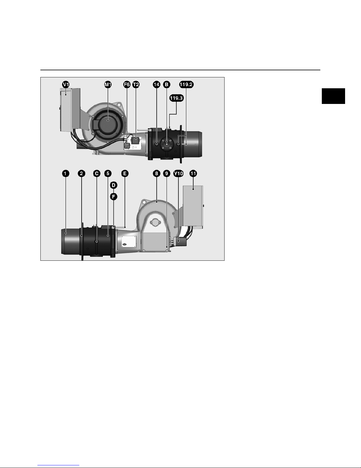
Key
B Gas train connecting flange
C Fixation screw nut for gas supply
line
E-F-D Mobile and fixed spindles and
safety screw
F6 Air pressure switch
M1 Blower motor
T2 Ignition transformer
V1 Fan motor variable speed
controller
Y10 Servomotor
1Blast tube
2 Spacer flange
5 Combustion head
identification plate
8 Housing (burner body)
9 Burner body identification plate
11 Electric control cabinet with TC
control panel
14 Air pressure tap for ventilation,
boiler window
119.2 Furnace pressure connector pF
119.3 Air pressure tap pL
en
Page 4

05/2009 - Art. Nr. 4200 1017 4400A4
General information
Packaging
Packaging
This is made up of three packages
delivered on two pallets with a total
average weight of 316 to 381 kg
depending on the model.
The burner body with:
- The electric control cabinet, integrated
or separate. In this case, a connection
box is placed on the burner which
contains:
- the operating instructions,
- the burner wiring diagram and
hydraulic diagram,
- the boiler room plate,
- the certificate of guarantee.
- The frequency variator mounted
against the electric control cabinet
The combustion head with:
- the boiler front gasket, a bag of nuts
and bolts, and two hinge spindles.
The gas train with:
- a set of flange valves,
- a bag of nuts and bolts, a PG21
support, rubber sheet gaskets, two pF
tubes, a pL pipe, a diagram,
- and a pre-assembled external filter.
Page 5
05/2009 - Art. Nr. 4200 1017 4400A 5
Installation
Assembly
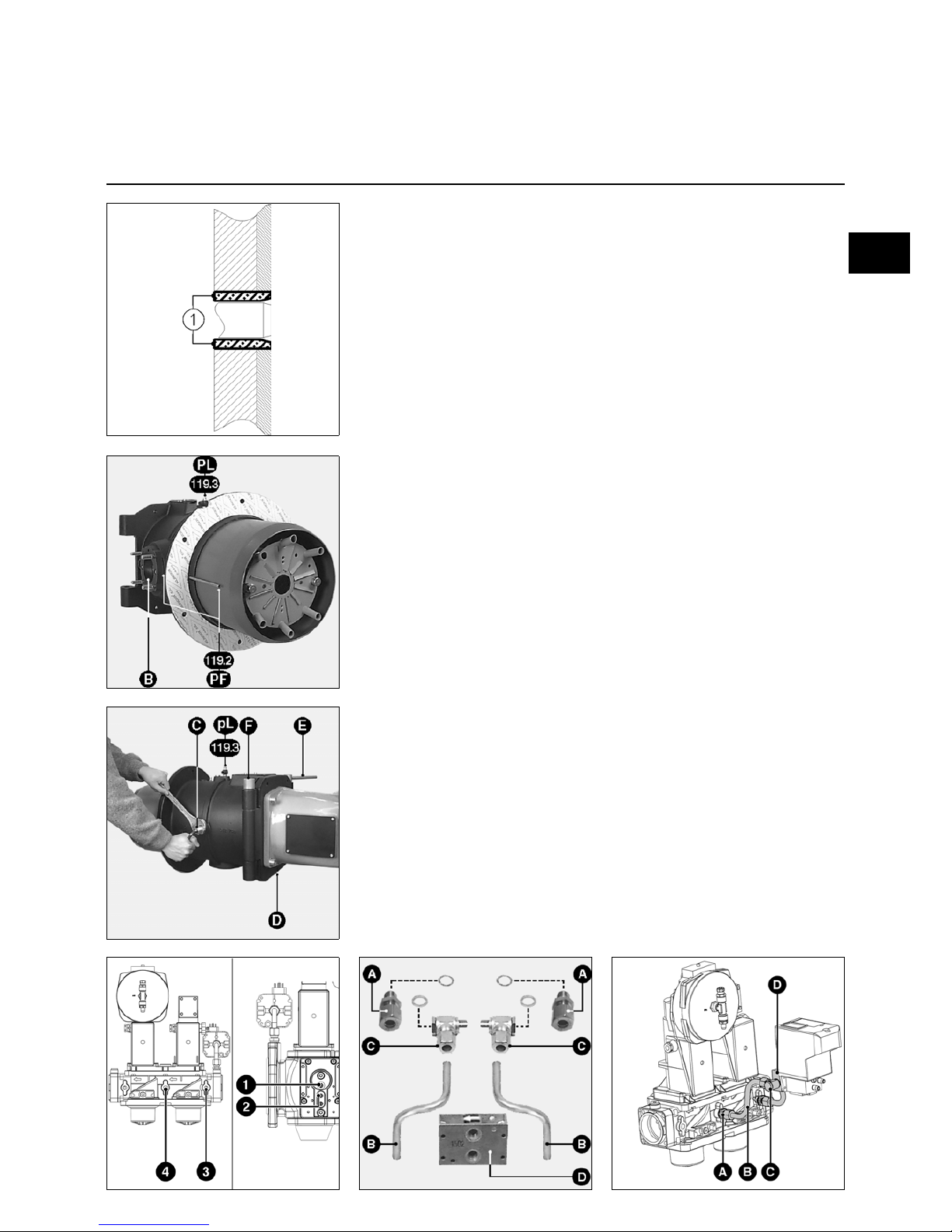
Boiler front
• Prepare the burner front as shown in
the annexed diagram of space
required.
• If necessary set up a backing plate for
the burner front (option).
• Pack the space 1 with a fire-resistant
material recommended or provided by
the boiler manufacturer.
Do not block the burner pressure tap
pF.
Combustion head
• Position the combustion head so that
the gas train is connected horizontally,
from the right.
• No other assembly positions are
authorised.
• Assemble and affix the combustion
head with its gasket to the boiler front.
• Check subsequently for leaks
Gas train
• Check the seal is fitted and correctly
positioned on the collector flange B.
• Position the support PG 21 (diagram).
• When fitting the gas train, the valve
coils must be in the vertical top
position.
Important
When using a VGD gas train fitted on the
left, the SKP75 regulator must be
pivoted 180°. In order to do this:
• Remove the SKP75 regulator.
• Remove the connector (3P+T) on the
side of the regulator, and refit it on the
opposite side.
Block the old connector housing.
• Refit the regulator after pivoting it by
half a turn (180°).
en
Burner body
• Attach the burner body to the burner
head using the fixed spindle F
opposite the gas train.
• Connect:
- The two ignition cables to the
transformer.
- The wire marked by a yellow tag, on
the ionisation probe cable.
• Close the burner body with the mobile
spindle E.
• Insert the safety screw D.
Connection of gas pressure connectors
• Link the valve connection pF to the
identified connection pF on the
combustion head with two pre-formed
reversible pipes (right - left) which are
coupled by a connection (see
diagram).
• Crimp the rings on the pipes.
• Link the pipe marked pL to the pL
connection on the valve.
• Tighten the nut by hand.
• Check subsequently for leaks.
Fitting the leak testing device
VPS 504 S02
Gas valve VGD20
• Remove the two caps 3 and 4 on the
VGD20 valve.
• Assemble the elements provided
according to illustrations opposite.
When fitting the hydraulic block, take
care of the flow direction.
• Fit the VPS504 on the connection
adapter D using the four delivered
self-tapping screws.
• Check presence of the O'Rings on the
leak controller.
• Connect the 7P connector to the VPS.
• Check tightness.
Gas valve VGD40
• Remove the two caps 1 and 2 on the
VGD40 valve.
• Check presence of the O'Rings on the
VPS.
• Fit the VPS using the four delivered
self-tapping screws.
• Connect the 7P connector to the VPS.
• Check tightness.
VGD 20 VGD 40
VGD 20
VGD20
Page 6

05/2009 - Art. Nr. 4200 1017 4400A6
Installation
Gas/electrical connections
Gas connection
The gas distribution system must be
connected to the gas train by a
technician.
The diameter of the piping must be
calculated so that load loss does not
exceed 5% of distribution pressure.
The external filter should be installed on
the valve with a clean connection piece,
in the horizontal position, with the cover
in the vertical position to ensure
maintenance access.
No other setup is authorised.
The quarter-turn hand-operated valve
(not supplied) should be assembled
upstream and as close as possible to the
external filter or to the valve (bag filter).
The threaded fittings used must comply
with current standards (tapered external
thread, parallel internal thread) and all
threads rendered leak-proof.
Allow enough space for access to set
the gas pressure switch.
Pipes must be drained upstream of the
quarter-turn hand-operated valve.
Connections performed in situ must be
tested for leaks using foam designed for
this purpose.
No leakage should be detected.
Electrical connection
The electrical setup and connections
must be performed in accordance with
the standards in force.
The earth wire must be connected
and tested.
See the diagram of electrics for
connecting the burner and its regulation.
The burner is delivered to be operated
with a 400 V- 50 Hz three-phase power
supply with neutral conductor and earth.
The blower motor is a direct start-up
motor.
A frequency variator can be installed as
an option.
Running on three phase
230 V - 50 Hz requires: the motor
couplings and switch thermal relays to
be replaced and a 630 VA isolating
transformer to be used on the control
circuit (not supplied).
For other voltages and frequencies,
please contact us.
Electrical connections
1) burner
- Integrated electric control cabinet.
• Use cable glands to guarantee the
degree of protection.
All the power and control connections
are connected to the control cabinet
terminal.
Ensure that you have sufficient cable
length to guarantee the rotation of the
burner body following setup.
• Check and adjust the rating of the
protection devices, the thermal relays
and the diameter of the wiring
according to the specifications of the
motor and the voltage available.
Wiring is not supplied.
- Separate electric control cabinet.
The control cabinet should be setup:
- either against a wall,
- or on a frame anchored to the
ground.
All the power and control connections
are connected between the control
cabinet and the connection box terminal
block on the burner body.
The other installation conditions are
identical to those for the integrated
control cabinet.
2) gas train
• Connect the standby points to the
valve:
- on the control cabinet,
- or on the connection box on the
burner body.
Page 7

05/2009 - Art. Nr. 4200 1017 4400A 7
Commissioning
Preliminary checks/leakage test
Setting the air pressure switch
Commissioning the burner also involves
simultaneous installation by the fitter or
his representative; only they can
guarantee the boiler room complies with
currently accepted practices and
regulations in force.
The fitter must first be in possession of a
“certificate of gas fuel conformity” issued
either by the approved body or
distributor and also have tested the
pipes upstream of the quarter-turn handoperated valve for leaks and drained it.
Preliminary checks
• Check the following:
- nominal available voltage and
electrical frequency and compare
them with values found on
identification plate,
- polarity between phase and neutral
- the previously tested earth wire
connection,
- lack of potential between neutral and
earth,
- the direction of rotation of the
motors.
- the thermal relays, in manual
position (H) only and the current
strength setting.
• Turn off the power supply.
• Check absence of voltage.
• Close the fuel valve.
• Read the service instructions provided
by the generator and regulator
manufacturers.
• Check the following:
- that the boiler is full of pressurised
water,
- that the circulator or circulators
work,
- that the mixer valve or valves are
open,
- that the combustion air supply and
combustion product exhaust duct
are operational and compatible with
the nominal output of the burner and
the fuels,
- that the draught regulator on the
smoke exhaust duct is in place and
working properly,
- that the electrical protection
equipment outside the burner is
present, calibrated and set,
- the boiler regulator circuit setting.
Setting the air pressure switch
• Remove the transparent cover.
The unit includes a index and
graduated mobile disc.
• Provisionally set the pressure
controller to the minimum value shown
on the graduated disc.
Leak check
• Connect a pressure gauge to the
pressure tap upstream of the gas
train.
• Open the quarter-turn hand-operated
valve.
• Check the supply pressure and its
stability over time.
• Check for the absence of leaks in the
gas train connections and the exterior
filter using foam designed for this
purpose.
No leakage should be detected.
• If necessary, vent the piping
downstream of the quarter-turn handoperated valve.
• Stop venting, remove the pressure
gauge, and close the pressure tap.
en
Page 8
05/2009 - Art. Nr. 4200 1017 4400A8
Commissioning
Settings check
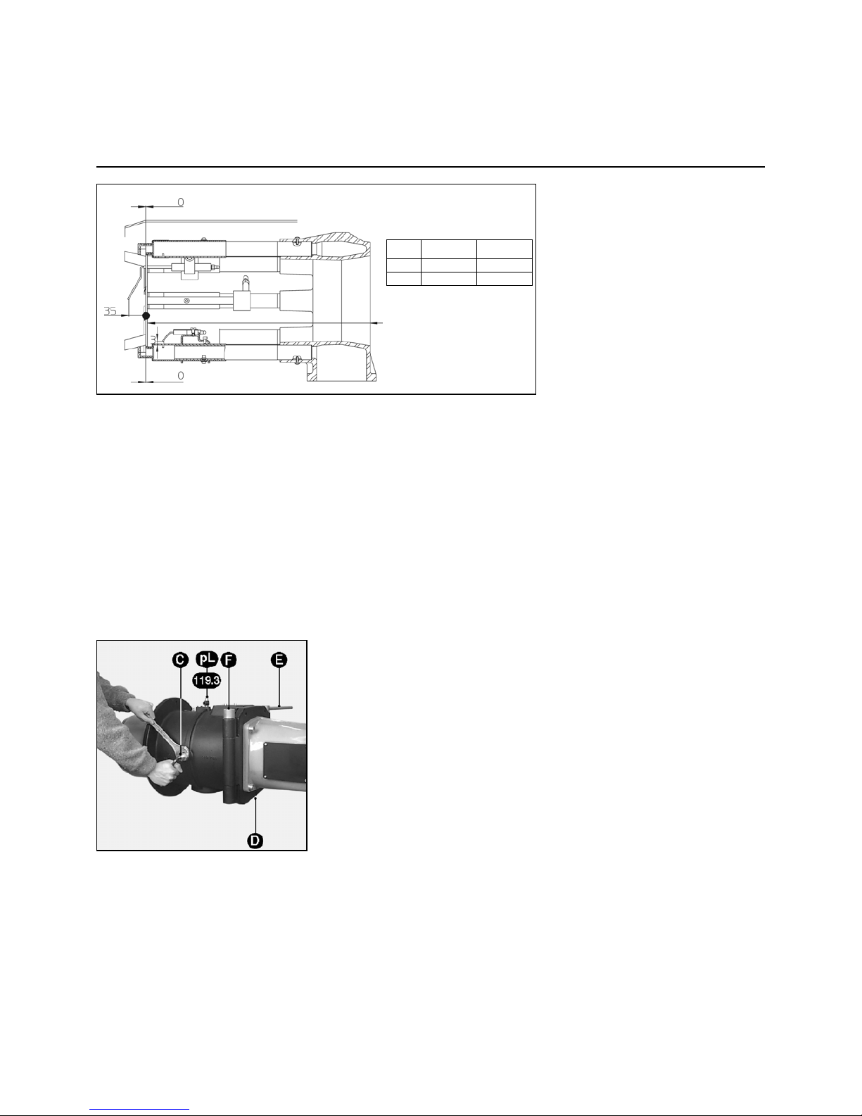
Combustion components
Secondary air
Secondary air (Y dimension)
It is the air flow admitted between the
different diameters of the baffle and the
blast tube.
On delivery, dimension Y is set to 453
for KN and 753 for KL.
However depending on:
- firing quality
(shock, vibration, judder, delay),
- the cleanliness of the gas flow
combustion,
this value can be changed.
Setting
This is done when the burner is stopped
by disassembling the combustion
elements following the process
described in the previous chapter.
By increasing dimension Y, the
secondary air is reduced and the CO
2
increases and vice versa.
• Unscrew the two screws from the
baffle support.
• Slide the baffle support in the desired
direction.
• Measure the dimension Y; tighten the
two screws again.
• Adjust the diffusers according to the
type of head and the gas used as per
the plan opposite.
• Reassemble.
• Check to ensure the presence and the
correct positioning of the sheet gasket
on the gas supply line.
Natural gases (low NOx)
Secondary
air (max)
Secondary
air (min)
T1 Y=453 Y=478
T2 Y=753 Y=778
Factory settings in bold type
Secondary
air (max)
Secondary
air (min)
KN Y=453 Y=478
KL Y=753 Y=778
Checking and setting combustion
head
On delivery the burner is set to natural
gases.
• Remove the safety screw D.
• Remove the movable pin E.
• Open the body of the burner.
• Disconnect the two ignition cables on
the transformer and the ionisation
probe cable.
• Unscrew the nut and the lateral screw
C which immobilises the gas supply
line.
• Remove the combustion components.
• Adjust the settings of the ignition
electrodes, the ionisation probe and
the diffusors according to the gas
available and the diagrams included.
• Check to ensure the presence and the
correct positioning of the sheet gasket
on the gas supply line.
• Reassemble.
• Check the following:
- the tightness of the screw and the
nut C,
- the leak tightness afterwards.
Page 9
05/2009 - Art. Nr. 4200 1017 4400A 9
Commissioning
Setting
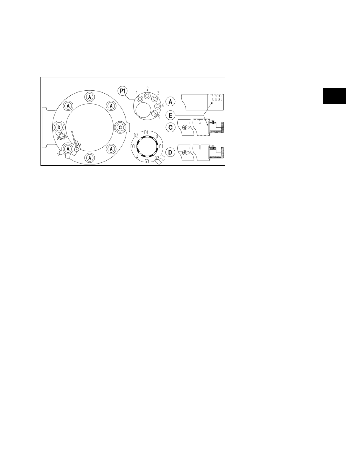
Diffusors, injectors
Factory setting for head - low NOx
natural gases
Diffusors A:
- Exterior slots completely closed.
- Downstream injector patch P1: screw
in position 5.
Diffusors C:
- Upstream slot closed,
- Downstream injector: screw in position
G2.
Ignition diffusor D:
- Slot open inside,
- Downstream injector screw in position
G2.
Natural gases (low NOx)
G/F-VT
en
Page 10
05/2009 - Art. Nr. 4200 1017 4400A10
Commissioning
Description of settings
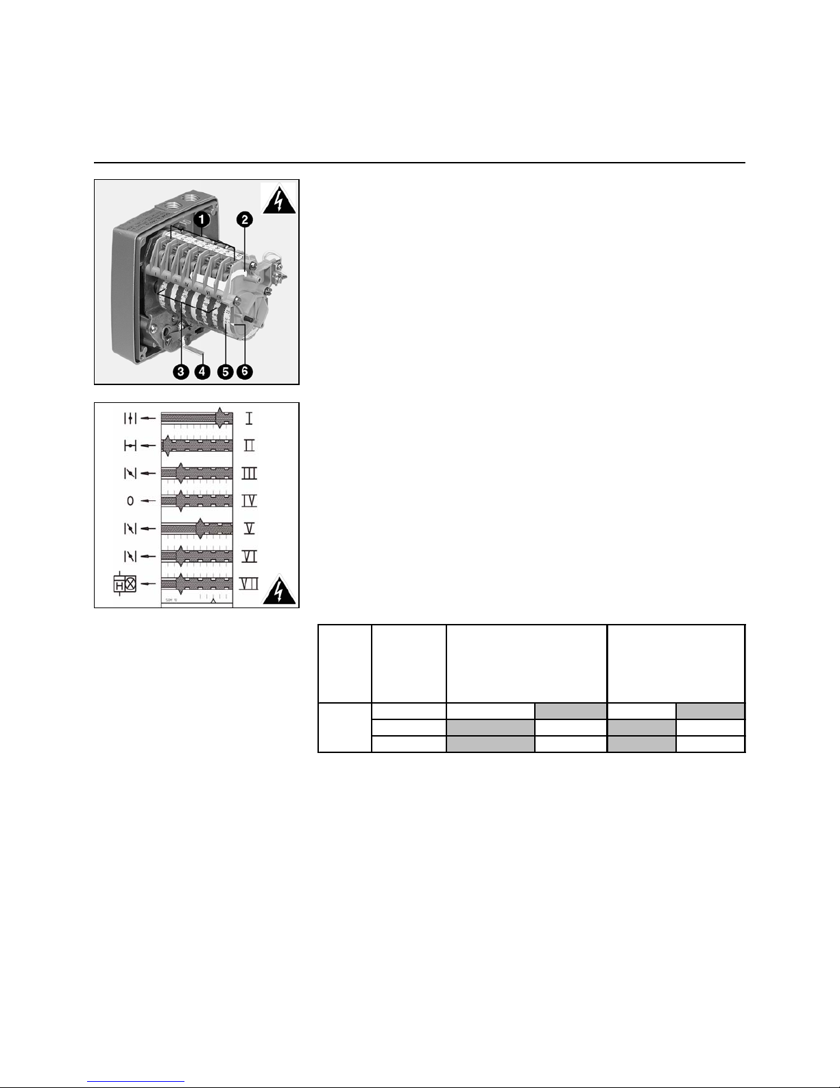
Combustion air
Servomotor Y10
1 Connection terminal board
2 Cam setting key
3 Seven adjustable graduated cams
4 Lever to operate the motor release
mechanism
5 Non adjustable graduated cylinder
for servomotor position
6 Graduated cylinder indicator
SQM 10 16
Cam functions
CamFunction
I Nominal air flow
II Air closure on shutdown 0
III Firing air flow
IV Free 0°
VCam V provides the minimum
control flow information (to be set
between the values of cam I and
VI)
VI Minimum control air flow
VII Simultaneously powering up of the
large flame indicator and lower
hour meter at nominal flow rate
only
• Set this a few degrees lower than
the value read on cam I.
Cam
VI
determines the automatic minimum
control flow after the ignition phase. In the
electric control cabinet, the timer
K6
sets
itself at
≅
15s.
Setting
• Remove the cover.
• Check the cam drum reset.
• Pre-set the cams according to the boiler
capacity and to the values read on the
table enclosed.
In order to do this:
• Adjust the cams manually or with the
key. The angular position can be read
from the indicators located on each
cam.
Type
Burner
power
kW
700 25 - 30 3100 - 70 - 51
5200 - 80 - 57
Air setting in °
i gnition n om ina l
c a m III cam I
ES08.
5200
Frequency in Hz
Ignition N om ina l
Page 11
05/2009 - Art. Nr. 4200 1017 4400A 11
Commissioning
Description and settings
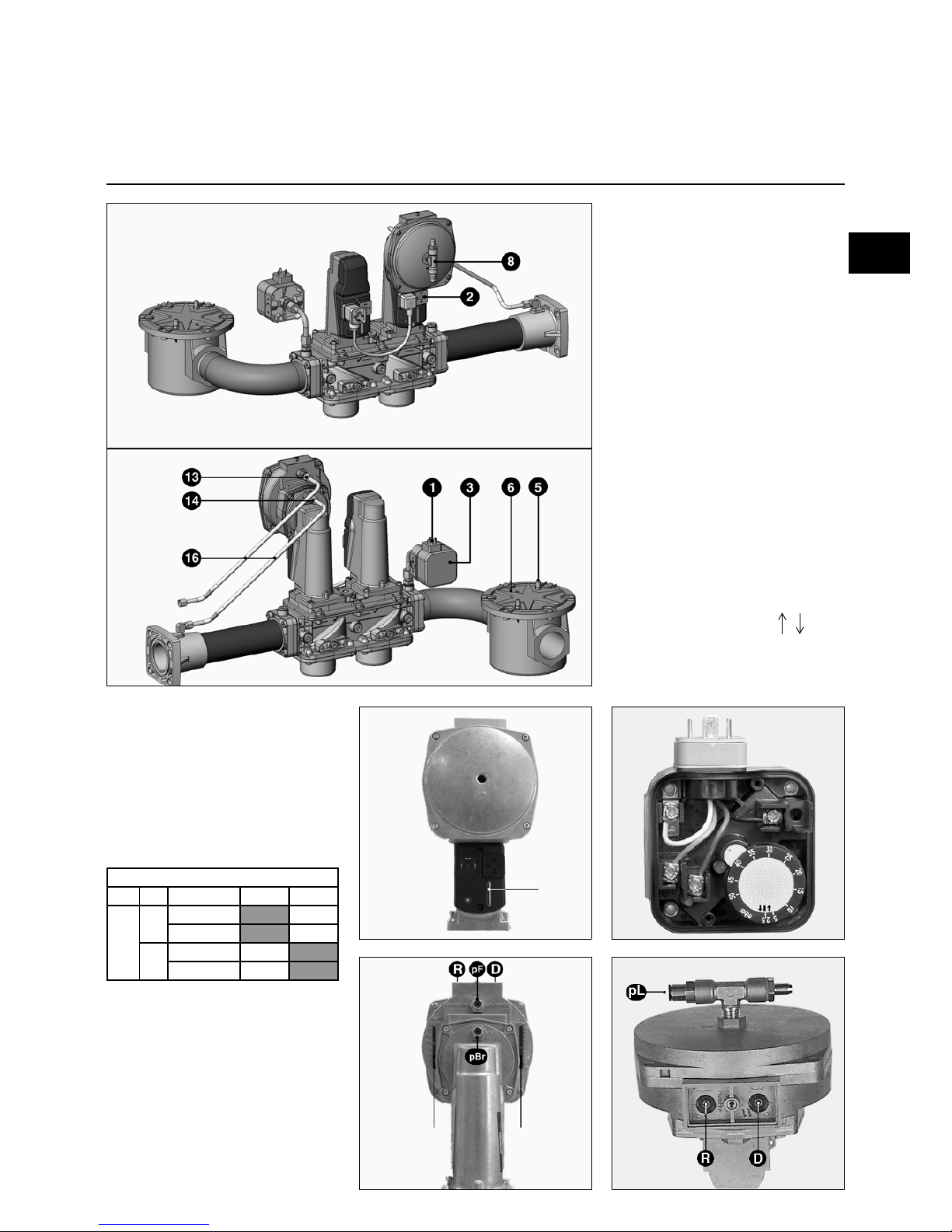
VGD gas valve
SKP75 regulator
1 Gas pressure switch connection
(DIN 43650)
2 Electric supply of the magnetic
valves (DIN 43650)
3 Pressure switch
4 Inlet flange
5 Pressure tap G 1/8 before the filter
6 DN65 external filter
7 Identification plate
8 Gas connection G 1/8 for air
pressure pL
9 Ratio adjustment screw R
12 Adjusting screw D for correcting
point 0.
13 Connection G 1/8 for the furnace
pressure pF
14 Connection G 1/8 for the gas
pressure pBr
15 Outlet flange
16 Pressure tap tubes pBr - pL - pF
Gas pressure switch setting
• Remove the transparent cover.
The unit includes an index |
and a mobile graduated disc.
• Set the pressure switch provisionally at
the minimum value indicated on the
graduated disc.
Gas valve
opening
indicator
Setting
index of the
ratio R
Setting
indicator D
The VGD valve connected to a SKP75
regulator is used to obtain a constant
gas/air flow ratio. The regulator also
takes account of the pressure pF in the
combustion chamber or the atmospheric
pressure.
On delivery, the regulator is pre-set
according to the table included.
en
ES08.5200 G/F-VT
Gas P 20.050 40.065
(Scr.
R
)
3
(Scr.
D
)
0
(Scr.
R
)
2.8
(Scr.
D
)
-0.1
VGD
Burner
G20
150
300
Page 12
05/2009 - Art. Nr. 4200 1017 4400A12
Commissioning
Description and settings
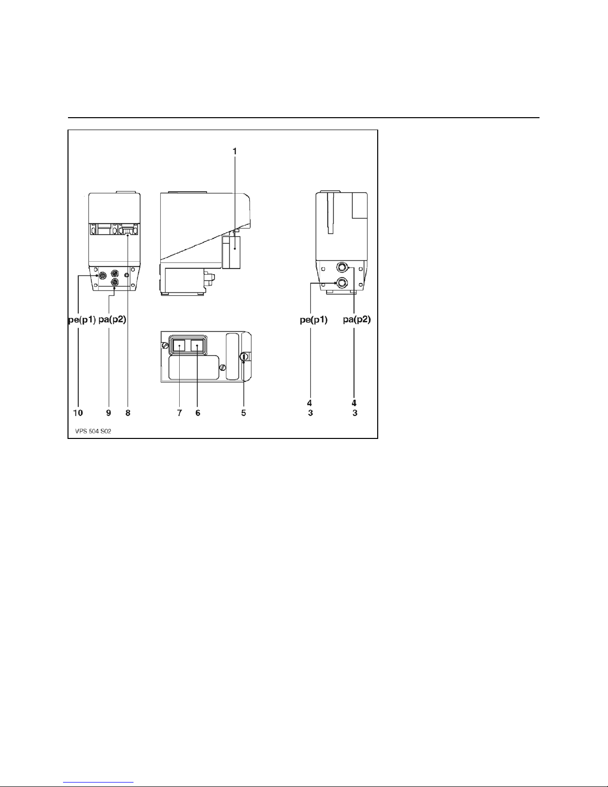
Gas valve/leak testing device
Leak testing device
VPS 504 S02
How it works:
Before each activation of the burner the
test device is used to test the leak
tightness between the safety valves and
the principle valves by raising the
distribution pressure.
Electrically the leak tightness test device
is connected in series between the
thermostatic circuit and the burner’s
control and safety unit.
Setup:
Directly onto the valve.
Program cycle:
When the burner is switched off the
safety valves and principle valves are
closed.
When the thermostat is closed, the leak
tightness test device is switched on and
the booster increases the distribution
pressure by 20 mbar.
After running for a maximum of 30
seconds:
- The leak test is validated; the yellow
light comes on, a voltage is released
to power the burner control and safety
unit, which begins its program.
- The leak test is not validated; the red
light comes on, power is not supplied
to the control and safety unit.
- Manual intervention is required to
relaunch a test cycle. If the problem
persists the valve must be changed.
Settings:
The leak tightness test device does not
need any on-site adjustments to its
setting.
Operating test:
While the leak testing device is in
operation.
• Open the pressure connector pa. The
leak generated prevents boosting and
after 30 secs the device will go into
safety mode.
• Reclose the pressure tap pa.
• Reset the leak tightness test device’s
safety catch by pressing the red
indicator.
The leak testing device restarts itself
and after 30 seconds the yellow light
comes on and the control and safety unit
is powered up and will start its program.
1 Wieland 7P connector. Female
3 Filter element
4 O-ring Ø 10.5 x 2.25
5 Fuse T6.3 250V Ø 5 x 20
6 Yellow light illuminated:
Leak test validated
7 Red light illuminated :
Leak test not validated Manual
unlocking
8 Spare fuse storage area
9 Pressure tap pa (p2) Ø 9
Test pressure: pe + 20 mbar
10 Pressure tap pe (p1) Ø 9 Inlet
pressure (distribution)
Page 13

05/2009 - Art. Nr. 4200 1017 4400A 13
Commissioning
Diagram of operation of the LFL 1.333 control unit
Required input signals
Output signals
Fault Air pressure switch Limiter Burner motor Transformer Fuel valve Regulation Servomotor Flame check Reset
t1 Preventilation time with air flap open
t2 Safety time
t2’ Safety time or 1st safety time for burner with pilot
t3 Short pre-ignition time (transformer terminal 16)
t3’ Long pre-ignition time (transformer terminal 15)
t4 Gap between voltage on terminal 18 (start t2) and 19 (BV1-BV2)
t4’ Gap between start of t2’ and 19 (BV2)
t5 Gap between voltage on terminal 19 and 20 (BV-Regul.)
t6 Postventilation time (with M2)
t7 Gap between start-up order and voltage on 7
t10 Interval between starting and air pressure check without the
Flap travel time
t11 Air flap travel time OPEN position
t12 Air flap travel time MIN position
t13 Accepted postcombustion time
t16 Gap to air flap opening order
en
Page 14

05/2009 - Art. Nr. 4200 1017 4400A14
Commissioning
Program of the LFL 1.333 (VARIO) control unit
Program of LFL 1.333 (VARIO) control
unit
t1:preventilation time 30s
t2:1st safety time 3s
t3:pre-ignition 6s
- :safety time on
flame extinguishing< 1s
Electrical operation
The LFL... control and safety unit is
designed for intermittent service, limited
to twenty-four hours of continued use.
For reasons of clarity, not all electrical
components are included in the
schematic diagram.
It is assumed that:
- the power supply is compliant.
- the servomotor pressure switches and
cams have been pre-set correctly.
Commands from control and safety unit.
Required input signals.
The terminal numbers
are those marked on
the base of the control
and safety unit.
Each phase of the control unit’s program
is identifiable by a symbol visible on a
rotating disc near to the reset button.
Program operating sequences:
Motor powered up (terminal 6) if
- mains voltage is supplied to
terminal 1,
- the air flap is closed: the voltage
on terminal 11 switches to
terminal 8,
- the air pressure regulator is at
rest: the voltage on terminal 12
switches to terminal 4,
- the thermostats (limiter and cutout) and the min gas pressure
switch are closed: the voltage on
terminal 4 switches to
terminal 5.
Servomotor control
(cam I) in wide open position
(terminal 9) with confirmation of
opening (terminal 8): start of
preventilation.
Start of permanent air pressure
check by the pressure switch and
confirmation at terminal 14: the
circuit between terminals 4 and 13
is broken.
Servomotor control
(cam III) in ignition position
(terminal 10) and confirmed of
position (terminal 8).
Start of pre-ignition (terminal 16).
Simultaneous opening of the safety
valve and main valve (terminal 18):
start of safety time.
Start of continuous monitoring of flame
presence.
Ignition transformer shutdown
shortly followed by
End of safety time.
Power control enabled (terminal
20).
Burner shut down by cut-off of the
limiter thermostat then servomotor
(cam II) closing position control.
During continuous operation, a
thermostatic cut-off is obligatory
after twenty-four hours.
Page 15
05/2009 - Art. Nr. 4200 1017 4400A 15
Commissioning
Description, functions
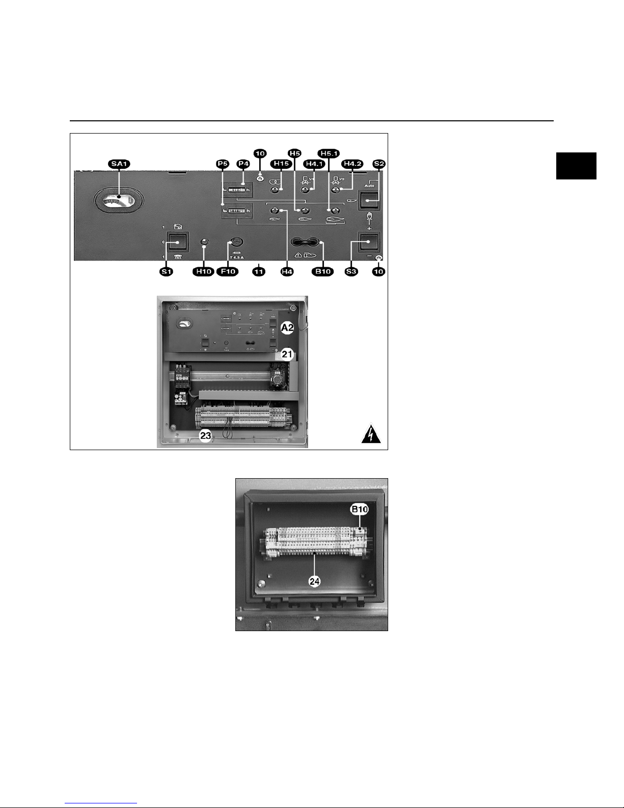
TC control panel
TC
Description of functions of the TC
(Control Panel)
A2 Option: 48 x 48 or 48 x 96 mm
standard positions for installing
an output regulator
B10 Measuring bridge [µA DC]
ionisation current
F10 TC fuse
Green lights
H4 Ignition flow rate
H4.1 Safety valve
H4.2 Main valve
H5 Minimum control flow rate
H5.1 Nominal flow rate
H10 TC on
H15 Transformer
P4 Total hours counter
P5 Nominal flow rate hour meter
Three position switch:
S1 TC main switch
0 Off
1& Local mode
1> Remote control mode
S2 Power control selector
' Manual mode with S3
Auto Automatic mode
with S1&
S3 By pulse with S2'
+/- Power
increase/decrease
SA1 The control unit shows:
- the program,
- faults, red light lit and reset
pushbutton.
10 Two screws to be removed to
access the unit and the option
positions
11 Under the TC, remove two
screws 10 and swing open:
Access to DIN 35 mm rail and
terminals for options
21 Identification plate
23 Detachable plate for the cable
glands
Electric control cabinet on burner
The electric control cabinet contains all
the components needed to operate the
burner. The lockable access door has a
control panel TC viewer window,
indicators and an inside documentation
storage pocket.
There is a detachable plate with the
various cable glands in the lower part of
the cabinet.
This highly accessible cabinet can have
various options fitted:
- A built-in output regulator of a
standardised 48 x 48 or 48 x 96 mm
size.
- Data transmission relays to be placed
on a DIN 35 mm rail available under
the control panel (remove two screws
10 and swing open).
Connection box on burner
Option for separate control cabinet
B10 Measuring bridge [µA DC]
ionisation current
24 Linking terminals between the
burner and the electrical
cabinet
en
Page 16

05/2009 - Art. Nr. 4200 1017 4400A16
Commissioning
Checking the operating sequence
Firing
Setting: safety checks
Checking the operating sequence
• Open the quarter-turn hand-operated
fuel valve, then immediately close it
again.
• Switch the burner on.
• On the control cabinet TC select the
manual operation mode
S1&- S2 '
• Close the thermostatic circuit.
The leak tightness test device VPS 504
S02 is switched on. After 30 seconds, if
the test is validated; the amber light
comes on. The control and safety unit is
powered on; the red light on the control
unit comes on
• Open the control unit and check that it
is working correctly.
The program should function in the
following way:
- complete opening of the air flap,
- preventilation for 30s,
- return to ignition position,
- 6-second electrode ignition,
- valves open,
- valves closed max 3 seconds after
opening,
- burner stops due lack of gas pressure
or control unit locks because flame
goes out.
If unsure, conduct the above test
again.
The unit can only be fired once this very
important operating sequence check
has been performed.
Firing
Warning:
The burner may be only fired when all
the requirements listed in previous
sections have been met.
• Connect a microammeter (scale 0 100 µA DC) in place of the measuring
bridge on the TC (check the polarity).
• Open the quarter-turn hand-operated
fuel valve.
• Close the thermostatic circuit.
The leak tightness test is switched on. At
the end of the test (30s), the unit is
switched on.
• Unlock the control and safety unit.
The burner is in service.
• Check the following:
- combustion as soon as flame
appears,
- any possible gas train leaks.
No leakage should be detected.
• Read the ionisation current (value
between 20 and 80µA inclusive).
• Measure the gas flow shown on the
counter.
• Raise the power to its nominal output
by activating the switch intermittently
S3+.
• Check combustion.
Comply with the smoke temperature
value recommended by the boiler
manufacturer in order to obtain the
required effective output.
According to the combustion tests, with
the burner operating at the nominal flow
rate turn screw V on the MB VEF valve,
or screw R on the SKP regulator.
• To increase the CO
2
rate, increase the
ratio and vice versa.
• Read the ionisation current (value
between 20 and 80µA inclusive).
• Measure the gas flow at the meter.
• Increase or reduce power by
increasing or reducing the value read
on the cam I graduated cylinder.
• Stop, then restart the burner.
• Check combustion as soon as the
flame appears.
According to the values measured, with
the burner operating, turn screw N on
the MB VEF valve, or screw D on the
SKP regulator.
• If necessary, adjust the cam III value
for ignition and the cam VI value for
minimum control.
Setting is performed in the same way
as for cam I.
• Return power to the nominal flow rate
and check the combustion
parameters.
If the value changes when screw N is
turned (screw D for the SKP), correct
the ratio V (R for the SKP) in the
desired direction.
• Obtain the best possible combustion
results by adjusting:
- the secondary air setting dimension
Y according to the procedure
described in the “Combustion
components and secondary air
head settings” section.
• Increase dimension Y: the CO
2
rate
increases and vice versa.
A modification made to the Y
dimension can necessitate a
correction of the air flow.
• Check combustion.
• Check operation during the following:
firing, increasing and decreasing
power.
• With the burner in operation check the
leak tightness of the gas train
connections using foam designed for
this purpose.
No leakage should be detected.
• Check the safety devices.
Setting and checking the safety
devices
Gas pressure switch.
• Set it to the minimum distribution
pressure.
The burner is in service at the firing flow
stage.
• Slowly close the quarter-turn handoperated fuel valve.
The burner must stop due to a lack of
gas pressure.
• Re-open the quarter-turn manual
valve.
The burner restarts automatically.
The pressure switch is set.
• Affix the cover and screw it on.
Air pressure switch.
The burner is operating at the firing flow
stage.
• Find the point where the air pressure
switch switches off (locking).
• Multiply the value read by 0.8 to obtain
the setting point.
• Restart the burner.
• Gradually block the air inlet.
• Check that the CO index is still below
10,000 ppm before resetting the
control unit.
If not, increase the air pressure switch
setting and repeat the test.
Leak testing device VPS :
• Open pa on the device.
• Restart the burner.
After 30s the device should enter safety
mode (red light on).
• Reclose pa.
• Unlock the tester safety catch by
pressing the red indicator.
The test cycle is relaunched.
The burner is in service.
• Check it is airtight.
• Disconnect the two wires on the
microammeter simultaneously.
The unit should reset itself immediately.
• Replace the measuring bridge and the
housings.
• Disconnect the measurement devices.
• Close the pressure taps.
• Unlock the unit.
The burner is in service.
• Check the following:
- the seal between the flange and the
boiler front,
- the opening of the control circuit
(limiter and safety),
- the current on the motor thermal
relays.
• Check the combustion under actual
operating conditions (doors closed,
etc.) and the circuit tightness.
• Record the results on the relevant
documents and give them to the
agent.
• Start-up automatic operation.
• Provide all the data required for proper
operation.
• Place the boiler room plate where it
can be easily seen.
Page 17
05/2009 - Art. Nr. 4200 1017 4400A 17
Commissioning
Frequency variator ACH550
1) Parameters programmed via the "Assistant" mode:
Parameter no.
9905
9906
9907
9908
9909
9902
Adjustment
400V
21.7A
50 Hz
2880 rpm
11 kW
HVAC Standard
Hand-Off-Auto Switch: NO
Continue with external threshold setting: --> Continue
Continue
1103
1301
1302
1104
1105
1106
1107
1108
2007
2008
EA1
20%
100.0%
25 Hz
60 Hz
PID OUTPUT
0.0%
100.0%
0.0 Hz
60 Hz
Continue with On/off
setting: --> Continue
Continue
1001
2101
2102
2202
2203
EL1
Train
Free wheel
10s
10s
Continue with protection device settings: --> Continue
Continue
Continue with constant speed
settings? --> Continue
Continue
1201
1202
EL3
5 Hz
Continue with the PID regulator? Continue
--> Continue
Continue with the reduced noise setting? --> Continue
Continue
2606
2601
2501
4 kHz
YES
NO
Continue with console display setting? --> Continue
Continue
Config. Variable Process 1: YES
3401
3402
3403
3404
3405
3406
3407
OUTPUT FREQ.
0.0 Hz
500.0 Hz
DIRECT
%
0.0%
1000.0%
2003
2014
no. 21.8A
Max torque 1
Configure Start-up and
On validation controls? YES
Parameter no.
1601
1608
1609
Adjustment
NO Select
NO Select
NO Select
Configure Emergency
shutdown controls? YES
2109
2208
No Select
1.0s
Configure fault functions? YES
3001
3021
3022
3003
3004
NO Select
0.0%
0.0%
NO Select
NO Select
Configure Autoreset Functions? YES
3104
3105
3106
3107
3108
3101
3102
3103
INACTIVE
INACTIVE
INACTIVE
INACTIVE
INACTIVE
5
30.0s
6.0s
Config. Variable Process 3: YES
The variator is pre-set in the factory.
The settings indicated below are given as a guide.
For further information, please see the manufacturer's website: www.abb.com
en
Page 18
05/2009 - Art. Nr. 4200 1017 4400A18
3415
3416
3417
3418
3419
3420
3421
EA1
0.0%
100.0%
DIRECT
V
0.0V
10.0V
Continue with timer function
settings? Continue
--> Continue
Continue with output settings? --> Continue
Continue
1401
1402
1403
READY
ON
FAULT (-1)
Use timer on relay outputs: NO
Configure analogue outputs: NO
Do you want to copy parameters to
console? NO
Config. Variable Process 2: YES
3408
3409
3410
3411
3412
3413
3414
CURRENT
no. 0.0A
no. 46.0A
DIRECT
A
no. 0.0A
no. 46.0A
2) Parameters programmed outside of
"Assistant" mode (in "Parameter" mode):
2001
2002
2007
2008
9901
1003
0 rpm
3440 rpm
0 Hz
60 Hz
Français
Rear
Commissioning
Frequency variator ACH550
Page 19

05/2009 - Art. Nr. 4200 1017 4400A 19
Maintenance
Important
The burner should be serviced at least
once a year by a trained specialist.
• Turn off power supply at the multipole
switch.
• Check absence of voltage.
• Close the fuel input.
• Check for leaks.
Do not use pressurised fluid or
chlorinated products.
The setting values are indicated in the
paragraph: “Start-up”.
Use only original spare parts.
Dismantling the blast tube.
This operation requires:
- either the burner body and boiler door
to be opened,
- or the burner to be removed.
1) Access via boiler door: Proceed as
indicated at the start of the previous
section as far as 4 “remove the
combustion components” then ...
• Unscrew the three blast tube screws
from the inside.
• Change the blast tube.
• If required, fill the space between the
quarl and the new blast tube with
refractory material.
Do not obstruct the
pressure tap pF.
• Reassemble.
2) Removing the burner:
Proceed as indicated at the start of the
previous section as far as 4 “remove the
combustion components” then ...
• Remove: the hoses, the burner body,
the gas train and the combustion
head.
• Unscrew the three blast tube screws
from the inside.
• Change the blast-tube and the front
seal.
• Reassemble.
Cleaning the air supply system
According to the current strength and
burner operating conditions:
• Clean the air supply system; blower,
the air flap and burner body.
• Reassemble.
• Check the direction of rotation of the
fan motor.
Checking the gas filter
The exterior filter or the filter on the valve
(integrated or bag) must be checked at
least once a year and the filtering
element must be changed when
clogged.
• Remove the cover screws.
• Remove the filter element. Make sure
no dirt is left in its housing.
• Install a new identical element.
• Replace the seal, cover and fastening
screws.
• Open the quarter-turn manual fuel
valve.
• Check it is airtight.
• Check combustion.
Leak testing device
• Remove the leak testing device.
• Check or replace the filter elements on
pe and pa.
• Reassemble.
• Check functioning and absence of
leaks.
Gas valves
These valves do not require any special
maintenance.
No intervention is authorised.
Faulty valves must be replaced by a
technician, who will then carry out the
sealing, performance and combustion
tests.
Checking the connections
In the electric control cabinet, on the
connection terminal board, servomotor,
the blower motor.
• Check that wiring on all terminals is
securely fastened.
Note
After any intervention:
• Check combustion under actual
operating conditions (doors closed,
etc.), and test there are no leaks in the
different systems.
• Perform safety checks.
• Record results in the relevant
documents.
Checking the combustion
components
• Remove the electrical sockets and
pressure taps on the gas train.
• Remove the safety screw D.
• Remove the mobile spindle E.
• Open the body of the burner.
• Disconnect the two ignition cables on
the transformer and the ionisation
probe cable.
• Unscrew the nut and the lateral screw
C which immobilise the gas supply
line.
• Remove the combustion components.
4
• Clean thoroughly.
• Check the condition and settings:
of the baffle, the ignition electrodes,
the ionisation probe, the diffusors, the
ionisation and ignition cables.
• Change any defective parts.
• Check to ensure the presence and the
correct positioning of the sheet gasket
on the gas supply line.
• Reassemble.
• Check the tightness of the screw and
the nut C.
en
Page 20

05/2009 - Art. Nr. 4200 1017 4400A20
Troubleshooting
Symbols
Fault Cause Corrective action
Burner stopped in service position
nothing happens.
Insufficient gas pressure. Adjust distribution pressure
Clean filter.
Gas pressure normal. Gas pressure switch set wrongly or
defective.
Air pressure switch closed (contact
welded).
Set or replace gas pressure switch.
Replace air pressure switch.
With leak testing device. Leak testing device shutdown.
Leak testing device not switched on.
Unscrew or change valve.
Check, change fuse.
Burner shut down
in service position.
Parasitic flame on thermostatic cut-off. Check gas valves for leaks.
Fit a postventilation device
P In “P” position.
Motor not working. Protection device open Faulty air pressure
Thermal relay tripped.
Protection device defective.
Replace air pressure switch.
Reset, adjust or replace thermal relay.
Replace protection device.
Motor not working.
Protection device closed.
Faulty wiring between protection device
and motor
Motor defective.
Check wiring
Replace motor
1
Motor running.
in service position.
In “1” position.
Air pressure switch wrongly set or
defective.
Faulty flame monitoring circuit
Adjust or replace the air pressure switch.
Check pressure pipes.
Check cell
Change control and safety unit
No ignition spark Ignition electrode(s) short circuit.
Ignition cable(s) damaged.
Faulty ignition transformer
Adjust or replace electrodes
Replace ignition cables
Replace ignition transformer.
Control and safety unit Change control unit
Solenoid valves
do not open.
Break in electrical connections. Check wiring between unit, servomotor
and valve
Coil(s) short-circuited. Replace coil(s).
Mechanical jamming in valves or
proportional regulator
Replace the valve.
Combustion head Combustion head wrongly set Adjust combustion head
Flame appears, but is
unstable or goes out (insufficient cell
current).
Air flap too open and/or gas flow too high Adjust air flap and/or gas flow.
I
Burner ventilation running continuously
without flame.
In “I” position.
on
or
On
Servomotor defective.
Air flap mechanically jammed
Coupling mechanically defective.
Adjust or change servomotor
Unblock air flap
Check or replace coupling.
Other incidents
Sudden lockout
at any time, not
indicated by any symbol.
Premature flame signal.
Old cell
Change control and safety unit
Replace the cell.
Control and safety unit recycle without
safety lockout
Gas pressure switch set wrongly or
defective.
Adjust or replace the gas pressure switch.
Check the following if failure
occurs:
• The presence of an electrical voltage
(power and control).
• The fuel supply (pressure and valve
opening).
• The regulation components.
• The position of the switches on the
control panel TC.
If the problem persists:
On the control and safety unit, check the
various program symbols described.
Safety components must not be
repaired but replaced by identical items.
Only use manufacturer spare parts.
Note
After any intervention:
• Check the combustion, and that the
various circuits are leak tight.
• Perform safety checks.
• Record results in the relevant
documents.
Page 21

02/2009 - Art. Nr. 4200 1017 4400A 21
Übersicht
Inhaltsverzeichnis
Gewährleistung, Sicherheit
Hauptvorschriften
Inhaltsverzeichnis
Übersicht
Gewährleistung, Sicherheit ................2
Hauptvorschriften ............................... 2
Gesamtansicht, Legende ...................3
Lieferumfang ......................................4
Technische Angaben
Siehe Technische Angaben
Nr. 4200 1017 4200
Installation
Montage .............................................5
Gasversorgung...................................6
Elektrische Versorgung ......................6
Inbetriebnahme
Kontrollen vor Inbetriebnahme .......... 7
Einstellungen........................... 7 bis 13
Programm des
Feuerungsautomaten ............ 14 bis 15
Schalttafel TC...................................16
Zündung ..........................................17
Einstellung und Kontrolle der
Sicherheitseinrichtungen................. 17
Wartung ...........................................18
Störungsbeseitigung .....................19
Gewährleistung
Montage und Inbetriebnahme müssen
fachgerecht von einem Techniker
durchgeführt werden.
Die geltenden Vorschriften sowie die
Hinweise dieser Anleitung sind zu
befolgen. Selbst bei einer nur teilweisen
Nichteinhaltung dieser Bestimmungen
kann der Hersteller die Übernahme der
Gewährleistung verweigern. Siehe
ebenfalls:
- den anliegenden Garantieschein,
- die allgemeinen
Verkaufsbedingungen.
Sicherheit
Der Brenner ist für die Ausrüstung von
Heizkesseln vorgesehen, die an
betriebsfähige Abzugsrohre für
Verbrennungsprodukte angeschlossen
sind.
Er darf nur in Räumen eingesetzt
werden, in denen ausreichende
Zuluftversorgung und die Abführung
eventueller Schadstoffe gewährleistet
sind.
Der Kamin muss laut geltenden
Bestimmungen und Normen
dimensioniert sein und dem Brennstoff
entsprechen.
Der Feuerungsautomat und die
verwendeten Abschaltvorrichtungen
erfordern eine Stromversorgung von
230 VAC % 50 Hz
±1%
.
Ferner muss der Nullleiter über das
gleiche elektrische Potential wie der
Schutzleiter verfügen.
Andernfalls muss die Stromzuleitung
zum Brenner über einen Isolationstrafo
mit geeigneten Schutzvorrichtungen
(Sicherung und
Differentialschutzschalter 30 mA)
erfolgen.
Für die korrekte Funktion des
Brenners ist bei Anschluss des 7poligen Steckers auf den polrichtigen
Anschluss der Leiter zu achten.
Der Brenner muss durch einen
genormten mehrpoligen Trennschalter
vom Netz getrennt werden können.
Das Servicepersonal ist in allen
Bereichen zu größter Vorsicht
angehalten, insbesondere ist jede
direkte Berührung nicht wärmeisolierter
Anlagenteile und Stromkreise zu
vermeiden.
Spritzwasser auf die elektrischen Teile
des Brenners ist zu vermeiden.
Bei Überschwemmung, Brand,
Brennstoffaustritt oder anormalem
Betrieb (verdächtiger Geruch oder
Geräusche, ...) ist der Brenner
abzuschalten, die
Hauptstromversorgung sowie die
Brennstoffzufuhr zu unterbrechen und
ein Techniker zu Rate zu ziehen.
Feuerräume, ihr Zubehör, Abgaszüge
und Anschlussrohre müssen vor
Inbetriebnahme des Brenners und dann
mindestens einmal jährlich gewartet,
gereinigt und gekehrt werden. Geltende
Bestimmungen beachten.
Grundsätzliche Bestimmungen “FR”
Wohngebäude
- Verordnung vom 2. August 1977 sowie
nachfolgende Änderungen:
Technische und sicherheitsrelevante
Vorschriften für Brenngas- und
Flüssigkohlenwasserstoffanlagen in
Wohngebäuden und deren
Nebengebäuden.
- Norm DTU P 45-204: Gasanlagen
(vorher DTU 61-1
- Gasanlagen - April 1982,
einschließlich der seither erstellten
Nachträge).
- Norm DTU 65.4: Technische
Vorschriften für Heizungsanlagen.
- Norm NF C15-100 Niederspannungsanlagen Bestimmungen
- Regionale Gesundheitsverordnungen.
Gebäude mit Öffentlichkeitsverkehr:
- Sicherheitsvorschrift gegen Brand und
Panik in Gebäuden mit
Öffentlichkeitsverkehr:
Allgemeine Bestimmungen:
- Artikel GZ (Brenngas- und
Flüssigkohlenwasserstoffanlagen);
- Artikel CH (Heizung, Belüftung,
Kühlung, Klimatisierung und
Herstellung von sanitärem Dampf und
Heißwasser);
Sonderbestimmungen für die jeweilige
Art von Gebäuden mit
Öffentlichkeitsverkehr.
Außerhalb “FR”
Berücksichtigen Sie örtliche Normen.
+
10
- 15
de
Page 22

02/2009 - Art. Nr. 4200 1017 4400A22
Übersicht
Gesamtansicht
Legende
Legende
B Anschlussflansch der Gasarmatur
C Schraube und Mutter für
Gaszuleitung
E-F-D Achsen, beweglich und fest,
Sicherheitsschraube
F6 Luftdruckwächter
M1 Gebläsemotor
T2 Zündtransformator
V1 Drehzahlregler des
Gebläsemotors
Y10 Stellantrieb
1 Flammrohr
2 Zwischenstück
5 Typenschild
des Brennkopfes
8 Brennergehäuse
9 Typenschild des
Brennergehäuses
11 Schaltschrank mit Schalttafel TC
14 Luftdruckabgriff für Belüftung
Kontrollfenster des Heizkessels
119.2 Feuerraumdruckabnahmeleitung
pF
119.3 Luftdruckabgriff pL
Page 23

02/2009 - Art. Nr. 4200 1017 4400A 23
Übersicht
Lieferumfang
Lieferumfang
Geliefert werden drei Pakete auf zwei
Paletten, je nach Ausführung mit einem
durchschnittlichen Gesamtgewicht von
316 bis 381 kg.
Das Brennergehäuse enthält:
- den Schaltschrank, eingebaut oder
separat; in diesem Fall befindet sich
ein Anschlusskasten mit folgendem
Inhalt am Brenner:
- Betriebsanleitung,
- Elektro- und Hydraulikschema des
Brenners,
- Schild der Kesselanlage,
- Garantieschein.
- den Frequenzregler, am
Schaltschrank befestigt
Der Brennkopf enthält:
- die Kesseltürdichtung, einen Beutel
mit Befestigungsmaterial, zwei
Scharnierachsen.
Die Gasarmaturengruppe enthält:
- einen Satz Gasrohrventile,
- einen Beutel mit Befestigungsmaterial,
einen Halter PG21,
Gummiflachdichtungen, zwei
Rohrleitungen pF, einen Schlauch pL,
einen Plan,
- einen vormontierten externen Filter.
de
Page 24

02/2009 - Art. Nr. 4200 1017 4400A24
Installation
Montage
Kesseltür
• Die Kesseltür anhand des
beiliegenden Maßblatts vorbereiten.
• Gegebenenfalls eine Deckplatte an
der Kesseltür anbringen (Option).
• Den Zwischenraum 1 mit vom
Kesselhersteller empfohlenem oder
mitgeliefertem feuerfestem Material
auskleiden.
Die Feuerraumdruckabnahmeleitung
pF nicht versperren.
Brennkopf
• Den Brennkopf für einen
waagerechten Anschluss der
Gasarmatur auf der rechten Seite
positionieren.
• Andere Montagepositionen sind nicht
zulässig.
• Den Brennkopf mit der zugehörigen
Dichtung an der Kesseltür montieren
und befestigen.
• Abschließend die Dichtigkeit
kontrollieren.
Gasarmatur
• Prüfen, ob die Dichtung am Flansch
des Gasrohres B vorhanden ist und
ob sie korrekt liegt.
• Den Halter PG 21 anbringen
(Abbildung).
• Die Gasarmatur muss so fixiert
werden, dass die Magnetspulen
senkrecht über der Gasarmatur
stehen.
Wichtig
Bei Verwendung einer linksseitig
montierten Gasarmatur VGD muss der
Druckregler SKP75 um 180° gedreht
werden. Hierzu:
• Den Druckregler SKP75 ausbauen.
• Den Stecker (3P+T) auf der Seite des
Druckreglers abbauen und auf der
gegenüberliegenden Seite wieder
montieren.
Den ursprünglichen Steckplatz
verschließen.
• Den Druckregler wieder montieren,
nachdem er umgedreht wurde (180°).
Brennergehäuse
• Das Brennergehäuse mit Hilfe der
festen Achse F auf der gegenüberliegenden Seite der Gasarmatur am
Brennkopf anhängen.
• Folgende Elemente anschließen:
- die beiden Zündkabel am Transformator,
- den mit einem gelben Etikett versehenen Draht am Kabel der Ionisationssonde.
• Das Brennergehäuse mit der bewegli-
chen Achse E verschließen.
• Die Sicherheitsschraube D anbringen.
Anschließen der Gasdruckanschlüsse
• Den Anschluss pF des Ventils mit dem
mit pF gekennzeichneten Anschluss
am Brennkopf verbinden; hierfür zwei
zweiseitige (rechts - links), vorgeformte Rohrleitungen verwenden, die
durch ein Anschlussstück zusammengefügt sind (siehe Abbildung).
• Die Ringe an den Rohrleitungen
umfalzen.
• Die mit pL gekennzeichnete Leitung
mit dem Anschluss pL des Ventils verbinden.
• Die Mutter von Hand festziehen.
• Abschließend die Dichtigkeit kontrollieren.
Montage des Dichtheitskontrollgeräts VPS 504 S02
VGD 20 Ventil
• Die beiden Verschlussstopfen 3 und 4
am Ventil VGD20 entfernen.
• Teile zusammenmontieren (siehe beiliegendes Bild).
Bei der Verteilereinsetzung ist die
Durchflußrichtung zu beachten.
• VPS504 am Anschlußadapter D mit
den vier mitgelieferten selbstschneidenden Schrauben befestigen.
• Darauf achten, daß die zwei O-Ringe
auf dem Dichtheitskontrollgerät
vorhanden sind.
• Elektrische Verbindung mittels 7P
Stecker am VPS herstellen.
• Auf Dichtheit prüfen.
VGD 40 Ventil
• Die beiden Verschlussstopfen 1 und 2
am Ventil VGD40 entfernen.
• Darauf achten, daß die zwei O-Ringe
am VPS vorhanden sind.
• Das Gerät VPS mit den vier mitgelieferten selbstschneidenden Schrauben
befestigen.
• Elektrische Verbindung mittels 7P
Stecker am VPS herstellen.
• Auf Dichtheit prüfen.
VGD 20 VGD 40
VGD 20
VGD20
Page 25

02/2009 - Art. Nr. 4200 1017 4400A 25
Installation
Gasversorgung und Stromversorgung
Gasversorgung
Der Anschluss der Gasarmatur an das
Gasnetz darf nur durch eine Fachkraft
ausgeführt werden.
Der Gasleitungsquerschnitt muss so
gewählt werden, dass die Druckverluste
5% des Netzdrucks nicht überschreiten.
Der externe Filter muss mit einem
sauberen Stutzen in waagerechter
Stellung und mit dem Deckel in
senkrechter Stellung am Ventil
eingebaut werden, damit eine Wartung
möglich ist.
Es ist keine andere Einbaulage
zulässig.
Der Kugelhahn (nicht im Lieferumfang
enthalten) wird stromaufwärts und
möglichst nah am externen Filter oder
am Ventil (Taschenfilter) montiert.
Die Gewinde der benutzten
Schraubverbindungen müssen den
geltenden Normen entsprechen, d.h. die
Außengewinde müssen konisch und die
Innengewinde zylindrisch mit
Gewindedichtung sein.
Um zur Einstellung des
Gasdruckwächters Zugang zu haben, ist
genügend Platz vorzusehen.
Die Leitung ist vor dem Kugelhahn zu
entlüften. Die vor Ort hergestellten
Anschlüsse müssen mit einem
geeigneten Schäummittel auf Dichtigkeit
überprüft werden.
Es darf kein Leck festgestellt werden.
Stromversorgung
Elektroinstallation und Anschlüsse
müssen gemäß den geltenden Normen
ausgeführt werden.
Die Erdung muss angeschlossen und
getestet sein.
Das Elektroschema für den Anschluss
des Brenners und des Druckreglers
beachten.
Der mitgelieferte Brenner ist für eine
Dreiphasenspannung mit 400 V / 50 Hz
mit Nullleiter und Erdung ausgelegt.
Der Gebläsemotor verfügt über einen
Direktanlauf.
Der Einbau eines Frequenzreglers ist
optional möglich.
Für den Dreiphasenbetrieb mit
230 V / 50 Hz ist Folgendes erforderlich:
Änderung der Schaltung der Motoren
sowie der Überstromrelais der Schütze
und Verwendung eines Isolationstrafos
mit 630 VA für den Steuerkreis (nicht im
Lieferumfang enthalten).
Für andere Netzspannungen und frequenzen bitte Cuenod kontaktieren.
Elektroanschlüsse
1) Brenner
- Eingebauter Schaltschrank
• Stopfbüchsen verwenden, um den
Schutzgrad zu gewährleisten.
Alle Verbindungen, Leistung und Antrieb
werden an der Klemmleiste des
Schaltschranks angeschlossen.
Eine ausreichende Kabellänge wählen,
um die für die Montage erforderliche
Kreisdrehung des Brennergehäuses zu
ermöglichen.
• Die Größe der Schütze und
Überstromrelais sowie den
Querschnitt der Drähte im Hinblick auf
die Eigenschaften des Motors und die
verfügbare Spannung überprüfen und
anpassen.
Die Verdrahtung wird nicht mitgeliefert.
- Separater Schaltschrank
Die Montage des Schaltschranks
erfolgt:
- entweder an einer Wand
- oder auf einem am Boden
befestigten Gestell.
Alle Verbindungen, Leistung und Antrieb
werden zwischen der Klemmleiste des
Schaltschranks und der Klemmleiste
des Anschlusskastens am
Brennergehäuse angeschlossen.
Die anderen Montagebedingungen
entsprechen denen des eingebauten
Schaltschranks.
2) Gasarmatur
• Am Ventil die beiseite gelegten
Stecker anschließen:
- entweder am Schaltschrank
- oder am Anschlusskasten am
Brennergehäuse.
de
Page 26

02/2009 - Art. Nr. 4200 1017 4400A26
Inbetriebnahme
Kontrollen vor Inbetriebnahme / Dichtigkeitskontrolle
Einstellung des Luftdruckwächters
Die Inbetriebnahme des Brenners sowie
der gesamten Anlage erfordert die
Anwesenheit des Installateurs oder
eines fachlich kompetenten Vertreters,
der allein die Garantie dafür
übernehmen kann, dass die
Heizungsanlage insgesamt dem Stand
der Technik und den geltenden
Bestimmungen entspricht.
Grundsätzlich muss der Installateur
über das Konformitätszeugnis für
Brenngas verfügen, das von der
zugelassenen Stelle oder dem
Netzbetreiber ausgestellt wurde.
Überdies muss er vorher die Dichtigkeit
der Anlage überprüft und die Leitungen
vor dem Kugelhahn entlüftet haben.
Kontrollen vor Inbetriebnahme
• Nun ist zu überprüfen:
- die Nennwerte der verfügbaren
Stromspannung und -frequenz;
diese sind mit den auf dem
Typenschild angegebenen Werten
zu vergleichen,
- die Polarität zwischen Phase und
Null-Leiter,
- der Anschluss des vorher getesteten
Erdungskabels,
- die Potentialabwesenheit zwischen
Nullleiter und Erdung,
- die Drehrichtung der Motoren.
- die Überstromrelais, nur in Position
manuell (H), und die Einstellung
der Stromstärke.
• Stromzufuhr abschalten.
• Überprüfen, dass keine Spannung
anliegt.
• Brennstoffventil schließen.
• Betriebsanweisungen des Kessel- und
Regelungsherstellers beachten.
• Nun ist zu überprüfen:
- dass der Heizkessel mit
ausreichend Wasser gefüllt ist,
- dass die Umwälzpumpe(n) in
Betrieb ist (sind),
- dass das (die) Mischventil(e) offen
ist (sind),
- dass die Frischluftzufuhr des
Brenners und das Abzugsrohr für
die Verbrennungsprodukte wirklich
in Betrieb sind und dass diese der
Nennleistung des Brenners und der
Brennstoffe entsprechen,
- dass der Zugregler am Abzugsrohr
vorhanden und betriebsbereit ist,
- dass die elektrischen
Schutzvorrichtungen außerhalb des
Brenners vorhanden, geeicht und
eingestellt sind,
- dass der Kesselregelungskreis
korrekt eingestellt ist.
Einstellung des Luftdruckwächters
• Durchsichtige Haube abnehmen.
Die Vorrichtung umfasst einen Zeiger
und eine bewegliche
Skalenscheibe.
• Auf der Skalenscheibe vorläufig den
kleinsten Wert einstellen.
Dichtheitskontrolle
• Am Druckanschluss vor der
Gasarmatur ein Manometer
anschließen.
• Kugelhahn öffnen und wieder
schließen.
• Eingangsdruck und seine zeitliche
Stabilität kontrollieren.
• Mit einem geeigneten Schäummittel
die Dichtigkeit der Anschlüsse der
Gasarmatur einschließlich des
externen Filters kontrollieren.
Es darf kein Leck festgestellt
werden.
• Die Leitung hinter dem Kugelhahn
gegebenenfalls entlüften.
• Die Lüftung wieder schließen, das
Manometer ausbauen und den
Druckanschluss schließen.
Page 27

02/2009 - Art. Nr. 4200 1017 4400A 27
Inbetriebnahme
Kontrolle und Einstellungen
Mischeinrichtung
Sekundärluft
Sekundärluft (Y-Maß)
Dabei handelt es sich um den
Luftdurchsatz zwischen den
verschiedenen
Stauscheibendurchmessern und dem
Flammrohr.
Im Auslieferungszustand ist das Y-Maß
für KN auf 453 und für KL auf 753
eingestellt.
Dieser Wert kann allerdings je nach:
- Zündqualität (Stöße, Schwingungen,
Rattern, Verzögerung),
- Verbrennungshygiene bei den
Gasdurchsätzen
geändert werden.
Einstellung
Die Einstellung erfolgt bei
abgeschaltetem Brenner und
ausgebauter Mischeinrichtung nach
dem Verfahren, das im vorhergehenden
Kapitel beschrieben wurde.
Durch Erhöhung des Y-Maßes
verringert sich die Sekundärluft und
steigt der CO
2
-Wert sowie umgekehrt.
• Die beiden Schrauben des
Stauscheibenhalters lösen.
• Den Stauscheibenhalter in die
gewünschte Richtung schieben.
• Den Y-Wert messen; die beiden
Schrauben wieder festziehen.
• Die Diffusoren je nach Brennkopftyp
und verwendeter Gasart anhand des
beiliegenden Plans justieren.
• Den Satz wieder zusammenbauen.
• Prüfen, ob die Flachdichtung an der
Gaszuleitung vorhanden ist und ob sie
korrekt liegt.
Erdgas - Low NOx
Sekundärl
uft max.
Sekundärl
uft min.
T1 Y=453 Y=478
T2 Y=753 Y=778
Fett gedruckt:
Werkseinstellungen
Sekundärl
uft max.
Sekundärl
uft min.
KN Y=453 Y=478
KL Y=753 Y=778
Kontrolle und Einstellungen der
Mischeinrichtung
Bei der Lieferung ist der Brenner auf
Erdgasbetrieb eingestellt.
• Die Sicherheitsschraube D entfernen.
• Die bewegliche Achse E entfernen.
• Das Brennergehäuse öffnen.
• Die beiden Zündkabel am
Transformator und das Kabel der
Ionisationssonde ausstecken.
• Die seitliche Mutter und Schraube C
lösen, die für die Arretierung der
Gaszuleitung bestimmt sind.
• Mischeinrichtung ausbauen.
• Die Einstellungen folgender Elemente
überprüfen: Zündelektroden,
Ionisationssonde, Diffusoren je nach
verfügbarer Gasart und entsprechend
der beiliegenden Abbildungen.
• Prüfen, ob die Flachdichtung an der
Gaszuleitung vorhanden ist und ob sie
korrekt liegt.
• Den Satz wieder zusammenbauen.
• Überprüfen:
- den festen Sitz von Schraube und
Mutter C,
- abschließend die Dichtigkeit.
de
Page 28

02/2009 - Art. Nr. 4200 1017 4400A28
Inbetriebnahme
Einstellungen
Diffusoren und Injektoren
Werkseinstellung des Brennkopfes Low NOx - Erdgas
Diffusoren A:
- Vollständig geschlossene
Außenschlitze.
- Injektoren stromabwärts in
Scheibenform P1: Schraube in
Position 5.
Diffusoren C:
- Schlitz stromaufwärts geschlossen,
- Injektor stromabwärts: Schraube in
Position G2.
Zünddiffusor D :
- offener Schlitz innen,
- Injektor stromabwärts, Schraube in
Position G2.
Erdgas - Low NOx
G/F-VT
Page 29

02/2009 - Art. Nr. 4200 1017 4400A 29
Inbetriebnahme
Beschreibung und Einstellungen
Verbrennungsluft
Stellantrieb Y10
1 Anschlussklemmleiste
2 Nockenschlüssel
3 sieben einstellbare Nocken mit
Skala
4 Hebel zum Auskuppeln des
Motors
5 nicht verstellbare Skala
für die Position des Stellantriebs
6 Zeiger der Skala
SQM 10 16
Nockenfunktion
Nocke Funktion
I Luftnenndurchsatz
II Luftabschluss bei Stillstand (0°)
III Luftdurchsatz der Zündung
IV Frei (0°)
VDie Nocke
V
liefert die Information
für den min. Regeldurchsatz , der
zwischen den Werten von Nocke
I
und VI eingestellt wird.
VI Min. Luft-Regeldurchsatz
VII Gleichzeitiges Einschalten der
Kontroll-Lampe für große Flamme
und des Betriebsstundenzählers
nur unterhalb des Nenndurchsatzes
• Auf einige Stufen unterhalb des an
Nocke
I
abgelesenen Wertes
einstellen.
Die Nocke
VI
bestimmt den minimalen
automatischen Regeldurchsatz nach der
Zündphase. Im Schaltschrank wird das
Zeitrelais
K6
auf ≅ 15 s eingestellt.
Einstellungen
• Brennerhaube abnehmen.
• Nullstellung der Nockentrommel
kontrollieren.
• Nocken entsprechend der
Kesselleistung und den in
nebenstehender Tabelle angegebenen
Werten voreinstellen.
Hierzu:
• Mit der Hand oder mit dem Schlüssel auf
die Nocken drücken. Die Winkelstellung
kann am Zeiger der einzelnen Nocken
abgelesen werden.
Typ
Brenner-
leistung
kW
700 25 - 30 3100 - 70 - 51
5200 - 80 - 57
Lufteinstellung in °
Zündlast Nennlast
Nocke III Nocke I
ES08.
5200
Frequenz in Hz
Zünd. Nenn.
de
Page 30

02/2009 - Art. Nr. 4200 1017 4400A30
Inbetriebnahme
Einstellung
Gasventil VGD
Druckregler SKP75
1 Elektrischer Anschluss des
Druckwächters (DIN 43650)
2 Elektroanschluss der
Magnetventile (DIN 43650)
3 Wächter
4 Eingangsflansch
5 Druckanschluss G 1/8 vor dem
Filter
6 Externer Filter DN65
7 Typenschild
8 Anschluss G 1/8 für Luftdruck pL
9 Stellschraube R für Verhältnis
12 Stellschraube D für Korrektur des
Nullpunktes
13 Anschluss G 1/8 für
Feuerraumdruck pF
14 Anschluss G 1/8 für Gasdruck pBr
15 Ausgangsflansch
16
Druckabnahmeleitungen
pBr - pL - pF
Einstellung Gasdruckwächter
• Durchsichtige Haube abnehmen.
Die Vorrichtung umfasst einen Zeiger
| und eine bewegliche
Skalenscheibe.
• Druckwächter vorläufig auf den
Mindestwert der Skalenscheibe
einstellen.
Öffnungsan
zeige des
Gasventils
Einstellanze
ige für
Verhältnis R
Einstellanz
eige D
Das Ventil VGD ermöglicht in
Verbindung mit einem Druckregler
SKP75 ein konstantes Verhältnis
zwischen Gasdurchsatz und
Luftdurchsatz. Der Druckregler
berücksichtigt ebenso den Druck pF in
der Brennkammer bzw. den
atmosphärischen Druck.
Bei der Lieferung ist der Druckregler
entsprechend der nebenstehenden
Tabelle voreingestellt.
ES08.5200 G/F-VT
Gas P 20.050 40.065
(Schr.R)
3
(Schr.D)
0
(Schr.R)
2.8
(Schr.D)
-0.1
VGD
Brenner
G20
150
300
Page 31

02/2009 - Art. Nr. 4200 1017 4400A 31
Inbetriebnahme
Einstellung
Dichtheitskontrollgerät / Gasventil
Dichtheitskontrollgerät
VPS 504 S02
Funktionsprinzip:
Anhand der Kontrollvorrichtung wird vor
jedem Starten des Brenners durch
Erhöhung des Netzdrucks die
Dichtigkeit zwischen dem
Sicherheitsventil und dem Haupthahn
getestet.
Das Dichtheitskontrollgerät wird in
Reihe zwischen Thermostatregelkreis
und Feuerungsautomat des Brenners
geschaltet.
Montage:
Direkt am Ventil.
Programmablauf:
Im Stillstand sind das Sicherheitsventil
und der Haupthahn geschlossen.
Bei der Thermostatabschaltung wird das
Dichtheitskontrollgerät eingeschaltet
und die Störschutzeinrichtung erhöht
den Netzdruck um 20 mbar.
Nach maximal 30 Sekunden
Betriebslaufzeit:
- Der Dichtheitstest wurde erfolgreich
durchgeführt; die gelbe Lampe
leuchtet auf, der Feuerungsautomat
des Brenners wird mit Spannung
versorgt und startet sein Programm.
- Der Dichtheitstest wurde nicht
erfolgreich durchgeführt; die rote
Lampe leuchtet auf, der
Feuerungsautomat wird nicht mit
Spannung versorgt.
- Ein manueller Eingriff ist erforderlich,
um einen neuen Dichtheitstest
einzuleiten. Wenn die Störung weiter
besteht, das Ventil austauschen.
Einstellung:
Das Dichtheitskontrollgerät erfordert
keine Einstellungen vor Ort.
Funktionstest:
Während das Dichtheitskontrollgerät
läuft:
• Den Druckanschluss pa öffnen. Das
erzeugte Leck verhindert das
Ansteigen auf Überdruck und nach 30
s schaltet das Gerät in den
Sicherheitsmodus.
• Den Druckanschluss pa wieder
schließen.
• Auf die rote Kontroll-Lampe drücken,
um den Sicherheitsmodus des
Dichtheitskontrollgerätes aufzuheben.
Das Dichtheitskontrollgerät startet
wieder; nach 30 Sekunden leuchtet die
gelbe Lampe auf, der
Feuerungsautomat wird mit Spannung
versorgt und startet sein Programm.
1 7-poliger Wielandstecker weiblich
3 Filterelement
4 Ringdichtung Ø 10,5 x 2,25
5 Sicherung T6,3 250 V Ø 5 x 20
6 Gelbe Kontroll-Lampe leuchtet:
Dichtheitstest erfolgreich
durchgeführt
7 Rote Kontroll-Lampe leuchtet:
Dichtheitstest nicht erfolgreich
durchgeführt, manuelle
Entriegelung
8 Aufbewahrung für
Austauschsicherung
9 Druckanschluss pa (p2) Ø 9
Testdruck: pe + 20 mbar
10 Druckanschluss pe (p1) Ø 9
Eingangsdruck (Netzdruck)
de
Page 32

02/2009 - Art. Nr. 4200 1017 4400A32
Inbetriebnahme
Funktionsdiagramm des Feuerungsautomaten LFL 1.333
Erforderliche Eingangssignale
Ausgangssignale
Störung Luftdruckwächter Begrenzer Brennermotor Transformator Gasventil Regelung Stellantrieb Flammenwächter Entriegelung
t1 Vorbelüftungszeit mit geöffneter Luftklappe
t2 Sicherheitszeit
t2’ Sicherheitszeit bzw. 1. Sicherheitszeit für Brenner mit Steuerung
t3 Zeit für kurze Vorzündung (Trafo Klemme 16)
t3 Zeit für lange Vorzündung (Trafo Klemme 15)
t4 Intervall zwischen Spannung an Klemme 18 (Beginn t2) und 19 (BV1-BV2)
t4’ Intervall zwischen Beginn von t2’ und 19 (BV2)
t5 Intervall zwischen Spannung an Klemme 19 und 20 (BV-Regulierung)
t6 Nachspülzeit (mit M2)
t7 Intervall zwischen Startbefehl und Spannung bei 7
t10 Intervall zwischen Start und Kontrolle des Luftdrucks ohne
Laufzeit der Luftklappe
t11 Laufzeit der Luftklappe in Position OFFEN
t12 Laufzeit der Luftklappe in Position MIN.
t13 Zulässige Nachbrennzeit
t16 Intervall bis Öffnungsbefehl für Luftklappe
Page 33

02/2009 - Art. Nr. 4200 1017 4400A 33
Inbetriebnahme
Programm des Feuerungsautomaten LFL 1.333 (VARIO)
Programm des Feuerungsautomaten
LFL 1.333 (VT)
t1:Vorbelüftungszeit 30 s
t2:1. Sicherheitszeit 3 s
t3:Vorzündungszeit 6 s
-:Sicherheitszeit bei
Flammenausfall< 1 s
Betrieb des Feuerungsautomaten
Der Feuerungsautomat LFL... ist für
einen diskontinuierlichen Betrieb von
höchstens 24 Stunden bei Dauerbetrieb
vorgesehen.
Um das Verständnis zu vereinfachen,
stellt das Prinzipdiagramm nicht alle
elektrischen Elemente dar.
Es wird angenommen, dass:
- die Stromzufuhr normgerecht ist,
- die Voreinstellung der Wächter und
der Nocken des Stellantriebs
vorschriftsmäßig durchgeführt wurde.
Steuersignale des
Automaten
Erforderliche
Eingangssignale
Die Klemmennummern entsprechen
den Nummern am Unterteil des
Feuerungsautomaten.
Jede Programmsequenz des
Feuerungsautomaten ist durch ein
Symbol gekennzeichnet, das auf einer
Drehscheibe neben dem Entstörknopf
abgelesen werden kann.
Ablauf der Programmsequenzen:
Einschalten des Motors (Klemme
6) in folgenden Fällen:
- an Klemme 1 liegt Netzspannung
an,
- die Luftklappe ist geschlossen:
die Spannung an Klemme 11
wird an Klemme 8 angelegt,
- der Luftdruckwächter befindet
sich in Ruhestellung: die
Spannung an Klemme 12 wird an
Klemme 4 angelegt,
- die Thermostate (Begrenzer und
Sicherheitsthermostat) und der
Gasdruckwächter sind
geschlossen: die Spannung an
Klemme 4 wird an Klemme
5 angelegt.
Steuerung des Stellantriebs
(Nocke I) in Position große Öffnung
(Klemme 9) mit
Öffnungsbestätigung (Klemme 8):
Beginn der Vorbelüftung
Beginn der permanenten Kontrolle
des Luftdrucks durch den
Druckwächter und Bestätigung an
Klemme 14: Schaltung zwischen
den Klemmen 4 und 13 ist
unterbrochen
Steuerung des Stellantriebs
(Nocke III) in Zündposition
(Klemme 10) mit
Positionsbestätigung (Klemme 8)
Beginn der Vorzündung (Klemme
16)
Gleichzeitiges Öffnen des
Sicherheitsventils und des
Haupthahns (Klemme 18): Beginn
der Sicherheitszeit
Beginn der permanenten Kontrolle der
Anwesenheit der Flamme
Abschaltung des
Zündtransformators und
unmittelbar danach Ende der
Sicherheitszeit
Freigabe für Leistungsregelung
(Klemme 20)
Abschaltung des Brenners durch
das Begrenzerthermostat,
anschließend Steuerung des
Stellantriebs (Nocke II) in
Schließstellung
Im Dauerbetrieb muss alle 24
Stunden eine
Thermostatabschaltung erfolgen.
de
Page 34

02/2009 - Art. Nr. 4200 1017 4400A34
Inbetriebnahme
Beschreibung und Funktionen
Schalttafel TC
TC
Beschreibung der Funktionen der TC
A2 Genormte Aufnahmen mit 48 x
48 oder 48 x 96 mm für den
Einbau eines Leistungsreglers
(Option)
B10 Messbrücke [µA DC]
Ionisationsstrom
F10 Sicherung der TC
grüne Kontroll-Lampen
H4 Zünddurchsatz
H4.1 Sicherheitsventil
H4.2 Haupthahn
H5 Min. Regeldurchsatz
H5.1 Nenndurchsatz
H10 TC eingeschaltet
H15 Transformator
P4 Gesamtbetriebsstundenzähler
P5 Betriebsstundenzähler für
Nenndurchsatz
Schalter mit drei
Schaltstellungen:
S1 Hauptschalter der TC
0 Aus
1& Lokalmodus
1> Ferngesteuerter Modus
S2 Wahl der Leistungsregelung
' Manueller Modus mit S3
Auto Automatischer Modus
mit S1&
S3 Wenn S2 ' in Position steht
+/- Erhöhung / Verringerung
der Leistung
SA1 Am Automaten, Anzeige:
- des Programms,
- der Störungen, rote KontrollLampe leuchtet und
Entstörknopf
10 Zwei Schrauben, die entfernt
werden müssen, um an den
Automaten und an die
Aufnahmen für die
Optionselemente zu gelangen
11 Unter der TC zwei Schrauben
10 entfernen und ankippen:
Zugang zur 35-mm-DINSchiene und zu den Klemmen
für die Optionselemente
21 Typenschild
23 Abnehmbares Schild für
Stopfbüchsen
Schaltschrank am Brenner
Der Schaltschrank enthält alle
Bauelemente, die für den Gerätebetrieb
erforderlich sind. Die verschließbare
Zugangsklappe ist mit einem
Sichtfenster für die Schalttafel TC, mit
Anzeigen und auf der Innenseite mit
einem Fach für die Dokumentation
ausgerüstet.
Im unteren Bereich befindet sich eine
abnehmbare Platte mit den einzelnen
Stopfbüchsen.
Der leicht zugängliche Schaltschrank
ermöglicht den Einbau verschiedener
Optionselemente:
- Leistungsregler in genormter
Aufnahme mit 48 x 48 oder 48 x
96 mm
- Relais für Datenfernübertragung, die
auf einer 35-mm-DIN-Schiene unter
der Schalttafel angebracht werden
(zwei Schrauben 10 entfernen und
ankippen).
Anschlusskasten am Brenner
Option für Schaltschrank außerhalb
des Brenners
B10 Messbrücke [µA DC]
Ionisationsstrom
24 Verbindungsklemmen
zwischen Brenner und
Schaltschrank
Page 35

02/2009 - Art. Nr. 4200 1017 4400A 35
Inbetriebnahme
Kontrolle des Programmablaufs
Zündung
Einstellung und Kontrolle der Sicherheitseinrichtungen
Kontrolle des Programmablaufs
• Kugelhahn öffnen und sofort wieder
schließen.
• Brenner einschalten.
• An der TC des Schaltschranks den
manuellen Modus wählen
S1&- S2 '.
• Thermostatregelkreis schließen.
Das Dichtheitskontrollgerät VPS 504
S02 wird eingeschaltet. Wenn der Test
erfolgreich ausgeführt wurde, leuchtet
nach 30 Sek. die orange Lampe auf. Der
Feuerungsautomat wird mit Spannung
versorgt; die rote Lampe des
Feuerungsautomaten leuchtet auf.
• Feuerungsautomat entriegeln und
seinen Betrieb kontrollieren.
Das Programm muss folgendermaßen
ablaufen:
- vollständige Öffnung der Luftklappe,
- Vorbelüftung (30 Sek.),
- Rückkehr in Zündstellung,
- Zündung der Elektroden (6 Sek.),
- Öffnen der Ventile,
- Schließen der Ventile spätestens 3
Sek. nach ihrer Öffnung,
- Brennerabschaltung aufgrund
mangelnden Gasdruckes oder
Verriegelung des Automaten aufgrund
Flammenausfalls.
Im Zweifelsfall den vorstehenden
Versuch wiederholen.
Erst nach dieser sehr wichtigen
Überprüfung des Programmablaufs darf
die Zündung erfolgen.
Zündung
Wichtig:
Die Zündung darf erst erfolgen, wenn
alle in den vorstehenden Kapiteln
genannten Bedingungen erfüllt sind.
• An Stelle der Messbrücke an der TC
ein Mikroamperemeter (Skala 0-
100 µA DC) anschließen. Polarität
beachten.
• Gaskugelhahn öffnen.
• Thermostatregelkreis schließen.
Die Dichtheitskontrolle wird
eingeschaltet. Nach Ablauf der Kontrolle
(30 Sek.) wird der Feuerungsautomat
eingeschaltet.
• Feuerungsautomat entriegeln.
Der Brenner steht in Betrieb.
• Überprüfen:
- die Verbrennung, sobald die
Flamme sichtbar wird,
- die Gesamtdichtigkeit der
Gasarmatur.
Es darf kein Leck festgestellt werden.
• Ionisationsstrom ablesen (Wert
zwischen 20 und 80 µA).
• Gasdurchsatz am Zähler messen.
• Leistung auf Nenndurchsatz durch
zeitweiliges Betätigen des Schalters
S3+ steigern.
• Verbrennung kontrollieren.
Vom Kesselhersteller empfohlene
Abgastemperaturwerte beachten, um
die geforderte Nutzleistung zu erzielen.
Die Schraube V des Ventils MB VEF
bzw. die Schraube R des Druckreglers
SKP je nach Verbrennungsergebnis
nachstellen, während der Brenner mit
Nenndurchsatz arbeitet.
• Zur Erhöhung des CO
2
-Wertes
Verhältnis vergrößern und umgekehrt.
• Ionisationsstrom ablesen (Wert
zwischen 20 und 80 µA).
• Gasdurchsatz am Zähler messen.
• Leistung durch Erhöhung oder
Verringerung des Skalenwertes der
Nocke I steigern oder reduzieren.
• Brenner abschalten und neu starten.
• Verbrennung kontrollieren, sobald
Flamme sichtbar wird.
Die Schraube N des Ventils MB VEF
bzw. die Schraube D des Druckreglers
SKP je nach gemessenen Werten
nachstellen, während der Brenner
arbeitet.
• Gegebenenfalls den Wert der Nocke
III für die Zündung und die Nocke VI
für die Minimalregelung nachstellen.
Die Einstellung erfolgt wie bei Nocke I.
• Leistung auf Nenndurchsatz steigern
und Verbrennung kontrollieren.
Hat sich der Wert durch das
Nachstellen der Schraube N
(Schraube D für Regler SKP)
verändert, Verhältnis V (R für Regler
SKP) in gewünschter Richtung
anpassen.
• Verbrennungsergebnisse verbessern.
Hierzu folgendermaßen vorgehen:
- Sekundärluft am Y-Maß
entsprechend den Anweisungen in
Kapitel „Einstellung der
Mischeinrichtung und der
Sekundärluft“ einstellen.
• Y-Maß erhöhen: Der CO
2
-Wert steigt
und umgekehrt.
Die Veränderung des Y-Maßes kann
eine Korrektur des Luftdurchsatzes
erfordern.
• Verbrennung kontrollieren.
• Den Betrieb beurteilen: bei der
Zündung, bei der Leistungssteigerung
oder -verringerung.
• Dichtigkeit der Anschlüsse der
Gasarmatur bei Brennerbetrieb mit
einem geeigneten Schäummittel
überprüfen.
Es darf kein Leck festgestellt werden.
• Sicherheitseinrichtungen kontrollieren.
Einstellung und Kontrolle der
Sicherheitseinrichtungen
Gasdruckwächter
• Auf minimalen Netzdruck einstellen.
Brennerbetrieb bei Zünddurchsatz
• Kugelhahn langsam schließen.
Der Brenner muss aufgrund von zu
geringem Gasdruck abschalten.
• Kugelhahn wieder öffnen.
Der Brenner startet automatisch neu.
Der Gasdruckwächter ist damit
eingestellt.
• Haube wieder aufsetzen.
Luftdruckwächter
Brennerbetrieb bei Zünddurchsatz
• Feststellen, wann der
Luftdruckwächter den Betrieb
unterbricht (Verriegelung).
• Ermittelten Wert mit 0,8 multiplizieren,
um Einstellungspunkt zu ermitteln.
• Brenner neu starten.
• Ansaugöffnung stufenweise
verschließen.
• Prüfen, ob der CO-Wert vor der
Verriegelung des Automaten unter
10 000 ppm liegt.
Ist dies nicht der Fall, die Einstellung
des Luftdruckwächters erhöhen und
den Test wiederholen.
Dichtheitskontrollgerät VPS:
• pa am Kontrollgerät öffnen.
• Brenner neu starten.
Nach 30 Sek. muss das Kontrollgerät in
den Sicherheitsmodus schalten (rote
Lampe leuchtet).
• pa wieder schließen.
• Auf die rote Kontroll-Lampe drücken,
um den Sicherheitsmodus des
Kontrollgeräts aufzuheben.
Der Kontrollzyklus wird nochmals
ausgeführt.
Der Brenner steht in Betrieb.
• Dichtigkeit überprüfen.
• Die beiden Kabel des
Mikroamperemeters gleichzeitig
abziehen.
Der Feuerungsautomat muss sich sofort
verriegeln.
• Messbrücke und Abdeckhauben
wieder anbringen.
• Messinstrumente abnehmen.
• Druckanschlüsse schließen.
• Feuerungsautomat entriegeln.
Der Brenner steht in Betrieb.
• Folgendes überprüfen:
- Dichtigkeit zwischen Flansch und
Kesseltür,
- Öffnung des Regelkreises
(Begrenzer und Sicherheitsmodus),
- Stromstärke für die Überstromrelais
der Motoren.
• Verbrennung sowie Dichtigkeit der
einzelnen Leitungen unter echten
Betriebsbedingungen (geschlossene
Türen etc.) überprüfen.
• Ergebnisse in den entsprechenden
Unterlagen dokumentieren und dem
Betreiber mitteilen.
• In den Automatikbetrieb schalten.
• Die für den Betrieb notwendigen
Informationen weitergeben.
• Schild der Kesselanlage sichtbar
anbringen.
de
Page 36

02/2009 - Art. Nr. 4200 1017 4400A36
Inbetriebnahme
Frequenzregler ACH550
1) Über den Assistentenmodus eingegebene Parameter:
Parameternr.
9905
9906
9907
9908
9909
9902
Einstellung
400 V
21,7 A
50 Hz
2880 min-1
11 kW
HVAC Standard
Hand-Off-Auto-Schalter: NEIN
Weiter mit Einstellung des Außenwertes: --> Weiter
Weiter
1103
1301
1302
1104
1105
1106
1107
1108
2007
2008
EA1
20 %
100,0 %
25 Hz
60 Hz
PID-AUSGANG
0,0 %
100,0 %
0,0 Hz
60 Hz
Weiter mit Einstellung für Einund Abschaltung: --> Weiter
Weiter
1001
2101
2102
2202
2203
EL1
Armatur
Freilauf
10 s
10 s
Weiter mit Einstellung der Schutzvorrichtungen: --> Weiter
Weiter
Weiter mit Einstellung der konstanten
Drehzahlen? --> Weiter
Weiter
1201
1202
EL3
5 Hz
Weiter mit PID-Regler? Weiter
--> Weiter
Weiter mit Einstellung der Geräuschreduzierung?--> Weiter
Weiter
2606
2601
2501
4 kHz
JA
NEIN
Weiter mit Einstellung der Konsolenanzeige? --> Weiter
Weiter
Konfig. Prozessvariable 1: JA
3401
3402
3403
3404
3405
3406
3407
AUSGANGSFREQUENZ
0,0 Hz
500,0 Hz
DIREKT
%
0,0 %
1000,0 %
2003
2014
21,8 A
Max. Drehmoment 1
Steuerungen für Start und
Einschaltbestätigung konfigurieren? JA
Parameternr.
1601
1608
1609
Einstellung
NEIN Auswahl
NEIN Auswahl
NEIN Auswahl
Notabschaltbefehle
konfigurieren? JA
2109
2208
Nein Auswahl
1,0 s
Störungsfunktionen konfigurieren? JA
3001
3021
3022
3003
3004
NEIN Auswahl
0,0 %
0,0 %
NEIN Auswahl
NEIN Auswahl
Autoresetfunktionen konfigurieren? JA
3104
3105
3106
3107
3108
3101
3102
3103
NICHT AKTIV
NICHT AKTIV
NICHT AKTIV
NICHT AKTIV
NICHT AKTIV
5
30,0 s
6,0 s
Konfig. Prozessvariable 3: JA
Der Frequenzregler ist ab Werk voreingestellt.
Die im Folgenden aufgelisteten Einstellungen werden zu Informationszwecken angegeben.
Weitere Informationen sind auf der Website des Herstellers abrufbar: www.abb.com
Page 37

02/2009 - Art. Nr. 4200 1017 4400A 37
3415
3416
3417
3418
3419
3420
3421
EA1
0,0 %
100,0 %
DIREKT
V
0,0 V
10,0 V
Weiter mit Einstellung der
Zeitschaltfunktionen? Weiter
--> Weiter
Weiter mit Einstellung der Ausgänge? --> Weiter
Weiter
1401
1402
1403
BEREIT
BETRIEB
STÖRUNG (-1)
Zeitschaltung an Relaisausgängen verwenden: NEIN
Analogausgänge konfigurieren: NEIN
Parameter auf Konsole
kopieren? NEIN
Konfig. Prozessvariable 2: JA
3408
3409
3410
3411
3412
3413
3414
STROMSTÄRKE
0,0 A
46,0 A
DIREKT
A
0,0 A
46,0 A
2) Außerhalb des Assistentenmodus eingegebene
Parameter (im Parametermodus):
2001
2002
2007
2008
9901
1003
0 min-1
3440 min-1
0 Hz
60 Hz
Français
Hinten
Inbetriebnahme
Frequenzregler ACH550
de
Page 38

02/2009 - Art. Nr. 4200 1017 4400A38
Wartung
Wichtig
Mindestens einmal jährlich durch einen
Techniker warten lassen.
• Stromzufuhr am Schutzschalter
abschalten.
• Überprüfen, dass keine Spannung
anliegt.
• Brennstoffzufuhr abschalten.
• Die Dichtigkeit überprüfen.
Kein unter Druck stehendes
Reinigungsmittel oder chlorhaltiges
Produkt verwenden.
Die Einstellwerte sind im Abschnitt
„Inbetriebnahme“ angegeben.
Nur Originalersatzteile verwenden.
Ausbau des Flammrohres
Für diesen Vorgang:
- müssen entweder das
Brennergehäuse und die Kesseltür
geöffnet werden
- oder muss der Brenner ausgebaut
werden.
1) Zugang über die Kesseltür: Die zu
Beginn des vorhergehenden Abschnitts
beschriebenen Arbeitsschritte bis 4
„Mischeinrichtung herausziehen“
ausführen, anschließend ...
• Die drei Schrauben des Flammrohres
von innen lösen.
• Flammrohr austauschen.
• Nötigenfalls den Zwischenraum
zwischen Feuerraumtür und neuem
Flammrohr mit feuerfestem Material
auskleiden.
Die Druckabnahmeleitung
pF nicht versperren.
• Den Satz wieder zusammenbauen.
2) Ausbau des Brenners:
Die zu Beginn des vorhergehenden
Abschnitts beschriebenen
Arbeitsschritte bis 4 „Mischeinrichtung
herausziehen“ ausführen, anschließend
...
• Folgende Teile ausbauen: Schläuche,
Brennergehäuse, Gasarmatur,
Brennkopf.
• Die drei Schrauben des Flammrohres
von innen lösen.
• Flammrohr und Kesseltürdichtung
austauschen.
• Den Satz wieder zusammenbauen.
Reinigung des Luftkreises
Je nach Stromstärke und
Nutzungsbedingungen des Brenners:
• Luftkreis reinigen; Gebläse, Luftklappe
und Brennergehäuse.
• Den Satz wieder zusammenbauen.
• Drehrichtung des Gebläsemotors
überprüfen.
Kontrolle des Gasfilters
Der externe oder am Ventil montierte
Filter (eingebaut oder Taschenfilter)
muss mindestens einmal jährlich
überprüft und das Filterelement bei
Verschmutzung ersetzt werden.
• Deckelschrauben entfernen.
• Filterelement herausnehmen und
darauf achten, dass in seinem Sitz
kein Schmutz zurückbleibt.
• Ein neues identisches Element
einsetzen.
• Dichtung, Deckel und
Befestigungsschrauben wieder
anbringen.
• Kugelhahn öffnen.
• Dichtigkeit überprüfen.
• Verbrennung kontrollieren.
Dichtheitskontrollgerät
• Dichtheitskontrollgerät ausbauen.
• Filterelemente an pe und pa
überprüfen bzw. austauschen.
• Den Satz wieder zusammenbauen.
• Funktions- und Dichtheitskontrolle
durchführen.
Gasventile
Die Ventile bedürfen keiner besonderen
Wartung.
Jeglicher Eingriff ist unzulässig.
Defekte Ventile müssen durch einen
Techniker ausgetauscht werden, der
anschließend auch neue Dichtigkeits-,
Funktions- und Verbrennungskontrollen
vornehmen muss.
Überprüfung der Anschlüsse
Im Schaltschrank, an der
Anschlussklemmleiste, am Stellantrieb
und am Gebläsemotor.
• Verdrahtung an allen Klemmen auf
festen Sitz überprüfen.
Hinweise
Nach jedem Eingriff:
• Verbrennung sowie Dichtheit der
einzelnen Leitungen unter echten
Betriebsbedingungen (geschlossene
Türen etc.) überprüfen.
• Sicherheitskontrollen durchführen.
• Ergebnisse in den entsprechenden
Unterlagen dokumentieren.
Kontrolle der Mischeinrichtung
• Die Elektro- und Druckanschlüsse an
der Gasarmatur entfernen.
• Die Sicherheitsschraube D entfernen.
• Die bewegliche Achse E entfernen.
• Das Brennergehäuse öffnen.
• Die beiden Zündkabel am
Transformator und das Kabel der
Ionisationssonde ausstecken.
• Die seitliche Mutter und Schraube C
lösen, die für die Arretierung der
Gaszuleitung bestimmt sind.
• Mischeinrichtung ausbauen.
4
• Die gesamte Vorrichtung reinigen.
• Zustand und Einstellungen folgender
Elemente überprüfen:
Stauscheibe, Zündelektroden,
Ionisationssonde, Diffusoren, Zündund Ionisationskabel.
• Defekte Teile ersetzen.
• Prüfen, ob die Flachdichtung an der
Gaszuleitung vorhanden ist und ob sie
korrekt liegt.
• Den Satz wieder zusammenbauen.
• Den festen Sitz von Schraube und
Mutter C überprüfen.
Page 39

02/2009 - Art. Nr. 4200 1017 4400A 39
Störungsbeseitigung
Symbole
Störung Ursache Beseitigung
Stillstand des Brenners in dieser Position
Es tut sich nichts
Ungenügender Gasdruck Versorgungsdruck einstellen
Filter reinigen
Gasdruck normal Gasdruckwächter falsch eingestellt oder
defekt
Luftdruckwächter geschlossen (Kontakt
verschweißt)
Gasdruckwächter einstellen oder
austauschen.
Luftdruckwächter austauschen.
Mit Dichtheitskontrolle Dichtheitskontrolle im Sicherheitsmodus
Dichtheitskontrolle ohne Spannung
Ventil entriegeln oder austauschen
Sicherung überprüfen, austauschen.
Sicherheitsabschaltung des Brenners
in dieser Position
Fremdlicht bei Thermostatabschaltung Dichtheit der Gasventile kontrollieren
Nachspülung durchführen
P in Position „P“
Motor dreht sich nicht Schütz ist geöffnet Luftdruckstörung
Überstromrelais ausgelöst
Schütz defekt
Luftdruckwächter austauschen
Überstromrelais zurückstellen, einstellen
oder austauschen
Schütz austauschen
Motor dreht sich nicht
Schütz ist geschlossen
Verkabelung zwischen Schütz und Motor
fehlerhaft
Motor defekt
Verkabelung überprüfen
Motor austauschen
1
Motor dreht sich
in dieser Position
in Position „1“
Luftdruckwächter falsch eingestellt oder
defekt
Störung im Flammenüberwachungskreis
Luftdruckwächter einstellen oder
austauschen
Druckleitungen überprüfen
Flammenwächter überprüfen
Feuerungsautomat austauschen
Kein Zündfunken. Kurzschluss der Zündelektrode(n).
Zündkabel beschädigt
Zündtrafo defekt
Elektroden einstellen oder austauschen
Zündkabel austauschen
Zündtransformator austauschen
Feuerungsautomat Feuerungsautomat austauschen
Elektromagnetventile
öffnen nicht
Elektrische Verbindungen unterbrochen Verkabelung zwischen
Feuerungsautomat, Stellantrieb und Ventil
überprüfen
Kurzschluss der Spule(n) Spule(n) austauschen
Mechanisches Blockieren an Ventilen oder
am Verhältnisregler
Ventil austauschen
Brennkopf Brennkopf falsch eingestellt Brennkopf einstellen
Die Flamme bildet sich, ist jedoch
unbeständig oder erlischt (unzureichender
Flammenwächterstrom)
Luftklappe zu weit geöffnet und/oder
Gasdurchsatz zu hoch
Luftklappe und/oder Gasdurchsatz
einstellen
I
Brenner in Dauerbelüftung
ohne Flamme
in Position „I“
auf
oder
auf
Defekt des Stellantriebs
Mechanisches Blockieren der Luftklappe
Mechanische Kupplung defekt
Stellantrieb einstellen oder austauschen
Luftklappe entriegeln
Kupplung überprüfen oder austauschen
Andere Störungen
Unbeabsichtigte Störabschaltung
zu einem beliebigen Zeitpunkt,
ohne Symbolanzeige
Vorzeitiges Flammensignal
Altern des Flammenwächters
Feuerungsautomat austauschen
Flammenwächter austauschen
Kreislaufbetrieb des Feuerungsautomaten
ohne Störabschaltung
Gasdruckwächter falsch eingestellt oder
defekt
Gasdruckwächter einstellen oder
austauschen
Bei einer Störung Folgendes
überprüfen:
• ob eine Spannung anliegt (Leistung
und Antrieb),
• ob die Brennstoffzufuhr funktioniert
(Ventildruck und -öffnung),
• die Einstellvorrichtungen,
• die Stellung der Schalter an der
Schalttafel TC.
Wenn die Störung weiter besteht:
• Am Feuerungsautomaten die
verschiedenen beschriebenen
Programmsymbole überprüfen.
Die Sicherheitskomponenten dürfen
nicht repariert werden, sondern müssen
durch Ersatzteile mit identischer
Teilenummer ersetzt werden.
Nur Originalersatzteile verwenden.
Hinweise
Nach jedem Eingriff:
• Verbrennungswerte sowie Dichtheit
der einzelnen Leitungen kontrollieren.
• Sicherheitskontrollen durchführen.
• Ergebnisse in den entsprechenden
Unterlagen dokumentieren.
de
Page 40

05/2009 - Art. Nr. 4200 1017 4400A40
Общие сведения
Содержание
Гарантийные обязательства, безопасность
Основные нормы
Содержание
Общие сведения
Гарантия, меры безопасности.........2
Основные нормы .............................. 2
Общий вид, условные
обозначения......................................3
Комплект поставки............................ 4
Технические характеристики
См. технические характеристики
№ 4200 1017 4200
Установка
Монтаж .............................................. 5
Подключение газа ............................ 6
Электроподключение .......................6
Ввод в эксплуатацию
Предварительные проверки ............7
Регулировки ...............................7 - 13
Программа блока
управления и безопасности ... 15 - 14
Панель управления TC ..................16
Розжиг..............................................17
Регулировка и проверка устройств
безопасности .................................17
Техничес кое обслуживание ........18
Обслуживание............................... 19
Гарантийные обязательства
Установка и пуск в
эксплуатацию
должны производиться с
соблюдением всех требований
техническим специалистом,
Обязательно соблюдайте все
действующие директивы и указания
руководства по эксплуатации.
Несоблюдение, в том числе
частичное, данных требований ведет
к аннулированию гарантии
производителя. См. также:
- гарантийный сертификат,
приложенный к горелке,
- общие условия продажи.
Безопасность
Горелка монтируется на печь, к
которой подсоединены трубопроводы
для отвода продуктов сгорания.
Данные трубопроводы должны
находиться в рабочем состоянии.
Устанавливайте горелку в месте, где
будет обеспечено достаточное
поступление приточного воздуха, а
также беспрепятственный отвод
продуктов сгорания.
Дымоход должен иметь правильно
рассчитанные размеры, его
параметры должны соответствовать
сжигаемому топливу и действующим
директивам и предписаниям.
Блок управления и безопасности и
используемые устройства
отключения требуют электрическое
питание: 230 В переменного тока
50 Гц
±1 %
.
Кроме того, нейтраль должна иметь
тот же электрический потенциал,
что и заземляющий провод.
В противном случае, электропитание
горелки должно подключаться через
изолирующий трансформатор, с
соблюдением необходимых условий
безопасности (предохранитель и
дифференциальный переключатель
30 мА).
Для правильной работы горелки
соблюдайте полярность
проводников при подключении 7полюсного разъема.
Горелка должна быть изолирована от
сети с помощью всеполюсного
размыкателя, соответствующего
действующим стандартам.
Обслуживающий персонал должен
соблюдать меры безопасности, в
особенности следует не допускать
прямого контакта с зонами без
теплоизоляции и электрическими
контурами.
Не допускайте попадания воды на
электрические части горелки.
При наводнении, пожаре, утечке
топлива или в каких-либо других
опасных ситуациях (запах,
подозрительные шумы
и т. д.)
остановите горелку, отключите
электропитание и подачу топлива и
вызовите квалифицированного
специалиста.
Техническое обслуживание, очистка и
прочистка камер сгорания, их
комплектующих, дымоходов,
патрубков должны проводиться как
минимум раз в год и перед запуском
горелки. См. параграф с
действующими нормами.
Основные действующие нормы
“РУС”
Жилое помещение:
- нормы, принятые
с 2 августа 1977,
а также последующие изменения и
дополнения: Технические нормы и
нормы безопасности для установок,
работающих на газе и жидком
углеводородном топливе,
использующихся в жилых или
производственных помещениях.
- Стандарт DTU P 45-204: Газовые
установки (ранее DTU № 61-1
- Газовые установки - апрель
1982 г.,
а также новые дополнения.
- Стандарт DTU 65.4: Технические
предписания для котельных.
- Стандарт NF C15-100 -
Низковольтные
электрические
установки + предписания.
- Предписание по соблюдению
санитарных норм.
Общественные помещения:
- Предписание о соблюдении мер
безопасности в случае
возникновения пожара и паники в
общественных помещениях:
Общие нормы:
- Пункты GZ (Установки на газе и
жидком углеводородном топливе);
- Пункты CH (Отопление,
вентиляция, охлаждение,
кондиционирование воздуха,
производство пара и воды для
бытовых нужд);
Индивидуальные предписания
для
каждого типа общественных
помещений.
Не на территории Франции
Действуют местные нормы и
предписания.
+
10
- 15
Page 41

05/2009 - Art. Nr. 4200 1017 4400A 41
Общие сведения
Общий вид
Условные обозначения
Условные обозначения
B Фланец присоединения газовой
рампы
C Болт и гайка крепления линии
подвода газа
E-F-D Стержни, подвижный и
неподвижный, и
предохранительный винт
F6 Воздушный регулятор
M1 Двигатель вентилятора
Т2 Трансформатор розжига
V1 Регулятор частоты вращения
двигателя вентилятора
Y10 Серводвигатель
1 Наконечник
2 Фланец вставки
5 Заводская табличка головки
горелки
8 Картер (корпус горелки)
9 Заводская табличка корпуса
горелки
11 Электрошкаф с панелью
управления
TC
14 Точка отбора давления воздуха
для вентиляции окна котла
119.2 Точка отбора давления в
камере сгорания pF
119.3 Точка отбора давления воздуха
pL
ruru
Page 42

05/2009 - Art. Nr. 4200 1017 4400A42
Общие сведения
Комплект поставки
Комплект поставки
В комплект поставки входят три
коробки на двух поддонах общим
средним весом от 316 до 381 кг, в
зависимости от модели.
Корпус горелки с:
- Встроенным или отдельным
электрошкафом. В этом случае на
горелке установлена клеммная
коробка, в которой находятся:
- руководство по эксплуатации,
- электрические и гидравлические
схемы горелки,
- табличка для
котельной,
- гарантийный сертификат.
- Частотный регулятор,
закрепленный на электрошкафу
Головка горелки с:
- прокладкой лицевой стороны котла,
пакетом с резьбовыми деталями
крепления, с двумя осями
шарниров.
Газовая рампа с:
- комплектом клапанов коллектора,
- пакетом с резьбовыми деталями
крепления, держателем PG21,
плоскими резиновыми
прокладками, двумя трубками pF,
трубкой pL, чертежом,
- предварительно установленным
внешним
фильтром.
Page 43

05/2009 - Art. Nr. 4200 1017 4400A 43
Установка
Монтаж
Лицевая сторона котла
• Подготовьте лицевую сторону котла
по прилагаемому габаритному
чертежу.
• При необходимости установите
переходную плиту лицевой
стороны котла (опция).
• Выполните футеровку проема 1
огнеупорным материалом,
предписанным или поставляемым
изготовителем котла.
Нельзя перекрывать точку отбора
давления в камере сгорания pF.
Головка горелки
• Установите головку горелки в
положение для горизонтального
присоединения газовой рампы
справа.
• Другие установочные положения не
допускаются.
• Установите и закрепите головку
горелки с ее прокладкой на лицевой
стороне котла.
• Обязательно проверьте
герметичность.
Газовая рампа
• Проверьте наличие и положение
прокладки на фланце коллектора B.
• Установите держатель PG 21
(чертеж).
• Закрепите газовую рампу, так чтобы
соленоиды клапанов были
обязательно установлены
в
верхнем вертикальном
положении.
Важно!
При использовании газовой рампы
VGD, устанавливаемой слева,
необходимо повернуть регулятор
SKP75 на 180°. Для этого:
• Снимите регулятор SKP75.
• Снимите разъем (3 фазы +
заземление), установленный сбоку
регулятора, и установите его с
противоположной стороны.
Заглушите место прежней
установки разъема.
• Установите регулятор,
предварительно повернув его на
пол-оборота (180°).
ru
Корпус горелки
• Прикрепите корпус горелки к головке
горелки с помощью неподвижного
стержня F, установленного со стороны,
противоположной газовой рампе.
• Присоедините:
- Два розжиговых кабеля к
трансформатору.
- Провод с желтой этикеткой к кабелю
датчика ионизации.
• Закройте корпус горелки с помощью
подвижного стержня E.
• Установите предохранительный винт D.
Присоединение точек измерения
давления газа
• Соедините муфту pF на клапане с
муфтой на головке горелки,
обозначенной pF, двумя реверсивными
трубками (справа–слева),
соединенными друг с другом (см.
рисунок).
• Отбортуйте кольца на трубках.
• Соедините трубку, обозначенную pL с
муфтой pL на клапане.
• Затяните гайку вручную.
• Обязательно проверьте герметичность.
Установка блока контроля
герметичности VPS 504 S02
Клапан
VGD 20
• На клапане VGD20 отверните два пробки
3 и 4.
• Соберите элементы из комплекта
поставки в соответствии с фотографией
ниже
Для распределительного устройства
соблюдайте направление потока
жидкости.
• Закрепите контроллер VPS504 на
соединительном адаптере D с помощью
четырех самонарезных болтов из
комплекта поставки.
• Убедитесь, что на контроллере
герметичности установлены два
кольцевых уплотнителя.
•
Присоедините разъем 7P. к блоку
контроля герметичности VPS.
• Проверьте герметичность.
Клапан VGD 40
• На клапане VGD20 отверните два пробки
1 и 2.
• Проверьте наличие двух
уплотнительных колец на блоке
контроля герметичности VPS.
• Закрепите блок контроля герметичности
VPS четырьмя поставляемыми
самонарезными винтами.
• Присоедините разъем 7P. к блоку
контроля герметичности VPS.
• Проверьте герметичность.
VGD 20 VGD 40
VGD 20
VGD20
Page 44

05/2009 - Art. Nr. 4200 1017 4400A44
Установка
Газо- и электроподключения
Подключение газа
Подключение
газораспределительной системы к
газовой рампе должно
осуществляться специалистом.
Сечение труб должно быть
рассчитано на потерю мощности,
не превышающую 5 % от давления
при подаче газа.
Для обеспечения технического
обслуживания внешний фильтр
должен быть установлен на клапане с
помощью чистой трубки,
горизонтально, с крышкой в
вертикальном положении.
Никакая другая установка не
допускается.
Ручной четвертьоборотный клапан
(не поставляется) должен быть
установлен перед внешним
фильтром или клапаном и как можно
ближе к нему (накладной фильтр).
Используемые резьбовые
соединения должны соответствовать
действующим нормам, внешняя
резьба - коническая, внутренняя
резьба - цилиндрическая,
обеспечивающая герметичность
соединений.
Предусмотрите доступ к регулятору
давления, необходимый для
осуществления его настройки.
Система труб
должна быть
прочищена на участке до ручного
четвертьоборотного клапана. Все
подключения, осуществляемые по
месту установки, должны быть
проверены на герметичность с
помощью пенообразующего состава.
Не должно быть никаких утечек!
Электроподключение
Электромонтаж и подключение
должны быть произведены в
соответствии с действующими
нормами.
Произведите и протестируйте
заземление.
Для подключения горелки и
регулятора см.
электросхему.
Горелка рассчитана на трехфазный
ток 400 В – 50 Гц с нулевым проводом
и заземлением.
Электродвигатель вентилятора
имеет схему непосредственного
пуска.
Возможна опционная установка
частотного регулятора.
Для работы на трехфазном токе
230 В - 50 Гц необходимо: изменение
схем подключения
электродвигателей, термореле
контакторов и применение
изолирующего трансформатора на
630 ВA в цепи управления ( в комплект
поставки
не входит).
В случае других значений
напряжения и частоты тока
обращайтесь к нам.
Электрические подключения
1) горелка
- Встроенный электрошкаф.
• Для обеспечения надлежащего
уровня защиты используйте
обжимные муфты для кабелей.
Соединения всех силовых цепей и
цепей управления должны быть
выполнены на контактной плате
электрошкафа.
Предусмотрите достаточную длину
кабелей, чтобы обеспечить
перемещение корпуса
горелки, в
различных вариантах установки.
• Проверьте и приведите калибровку
контакторов, термореле и сечение
проводов в соответствие с
характеристиками
электродвигателя и напряжением
тока.
Кабели в комплект поставки не
входят.
- Отдельный электрошкаф.
Электрошкаф устанавливается:
- либо на стене,
- либо на раме, закрепленной на
полу.
Соединения всех силовых цепей и
цепей управления должны
быть
выполнены с использованием
контактной платы электрошкафа и
клеммной коробки, установленной на
корпусе горелки.
Другие условия установки
аналогичны условиям для
встроенного электрошкафа.
2) газовой рампы
• Подсоедините свободные точки на
клапане:
- либо к электрошкафу,
- либо к клеммной коробке на
корпусе горелки.
Page 45

05/2009 - Art. Nr. 4200 1017 4400A 45
Ввод в эксплуатацию
Предварительные проверки/герметичность
Регулировка воздушного регулятора
Ответственность за запуск горелки и
всей отопительной установки в целом
лежит на установщике или его
представителе. Только эти лица
являются гарантами полного
соответствия установки правилам
эксплуатации и действующим
нормам.
Перед монтажом установки
проверьте наличие у установщика
разрешения на работы с
устройствами на газовом топливе,
выданного уполномоченным органом
или дилером компаниипроизводителя
. Перед запуском
установщик должен проверить
устройство на герметичность, а также
произвести продувку газопровода на
участке выше ручного
четвертьоборотного клапана.
Предварительные проверки
• Проверьте:
- номинальные рабочие значения
напряжения и частоты тока,
затем сравните их с данными,
указанными на заводской
табличке,
- полярность фазы и нейтрали,
- подключение заземленного
провода (предварительно
проверенного),
- отсутствие
потенциала между
нейтралью и заземлением.
- направление вращения
электродвигателей.
- термореле только в ручном (H)
положении и регулировку силы
тока.
• Выключите электропитание.
• Убедитесь в отсутствии напряжения
• Закройте топливный клапан.
• Прочтите инструкции заводов-
изготовителей по эксплуатации
теплогенератора и системы
регулирования.
• Проверьте:
- котел наполнен водой под
давлением,
- циркулятор(-ы) работает(-ют),
- смесительный(-е) клапан(-ы)
открыт(-ы),
- подача приточного воздуха к
горелке и отвод отработавших
газов осуществляются правильно
и соответствуют рабочей
мощности горелки и типу
топлива,
- наличие и работу регулятора тяги
на трубопроводе отвода
отработавших газов,
- наличие, калибровку, настройку
устройств электрической защиты
снаружи горелки,
- настройку контура регулирования
котла.
Регулировка
воздушного
регулятора
• Снимите прозрачную крышку.
Устройство имеет указатель и
градуированный подвижный диск.
• Предварительно установите
минимальное значение на
градуированном диске.
Проверка герметичности
• Присоедините манометр к точке
отбора давления перед газовой
рампой.
• Откройте и закройте ручной
четвертьоборотный клапан.
• Проверьте давление подачи
топлива и его стабильность.
• С помощью подходящего
пенообразующего состава,
проверьте герметичность
подсоединений к газовой рампе, в
том числе и подсоединение
внешнего фильтра.
Утечек не должно быть.
• Произведите, если необходимо
,
продувку газопровода на участке
после ручного четвертьоборотного
клапана.
• Закройте клапан продувки, снимите
манометр, закройте точку отбора
давления.
ru
Page 46

05/2009 - Art. Nr. 4200 1017 4400A46
Ввод в эксплуатацию
Проверка, регулировки
Устройства горения
Вторичный воздух
Вторичный воздух (размер Y)
Это расход воздуха, проходящего
между различными сечениями
дефлектора и наконечником.
При поставке размер Y установлен на
453 в KN и на 753 в KL.
В зависимости от:
- качества горения (удар, вибрация,
шум, задержки ),
- полноты сгорания при различных
расходах газа,
возможно изменять это значение.
Регулировка
Она выполняется на остановленной
горелке
и при снятых устройствах
горения в соответствии с процедурой,
приведенной в предыдущей главе.
При увеличении размера Y
уменьшается расход вторичного
воздуха и увеличивается содержание
CO
2
и наоборот.
• Ослабьте затяжку двух винтов
крепления держателя дефлектора.
• Сдвиньте держатель дефлектора в
нужном направлении.
• Измерьте размер Y; затяните оба
винта.
• По прилагаемому чертежу
приведите диффузоры в
соответствие с типом головки
горелки и используемым газом.
• Установите узел на место.
• Проверьте наличие и положение
плоской прокладки на линии
подвода газа.
Природный газ с низким выходом
окислов азота
Вторичны
й воздух
maxi
Вторичны
й воздух
mini
T1 Y=453 Y=478
T2 Y=753 Y=778
Жирным шрифтом
выделена заводская
настройка
Вторичны
й воздух
maxi
Вторичны
й воздух
mini
KN Y=453 Y=478
KL Y=753 Y=778
Проверка и настройки органов
горения
При поставке горелка отрегулирована
на природный газ.
• Снимите предохранительный винт
D.
• Снимите подвижный стержень E.
• Откройте корпус горелки.
• Отсоедините от трансформатора
оба кабеля розжига и кабель
датчика ионизации.
• Ослабьте затяжку гайки и бокового
винта C, фиксирующего линию
подвода газа.
• Выньте органы горения
• Проверьте
регулировки:
розжиговых электродов, датчика
ионизации, диффузоров на
соответствие используемому газу
по прилагаемым чертежам.
• Проверьте наличие и положение
плоской прокладки на линии
подвода газа.
• Установите снятые детали.
• Проверьте:
- затяжку винта и гайки C,
- герметичность.
Page 47

05/2009 - Art. Nr. 4200 1017 4400A 47
Ввод в эксплуатацию
Регулировки
Диффузоры, форсунки
Заводская регулировка головки
для природного газа с низким
выходом окислов азота
Диффузоры A:
- Наружные прорези полностью
закрыты.
- Форсунки за таблеткой P1: винт в
положении 5.
Диффузоры С:
- Входная прорезь закрыта,
- Форсунка на выходе: винт в
положении G2.
Форсунка розжига D:
- Прорезь открыта вовнутрь,
- Форсунка на выходе, винт в
положении G2.
Природный газ - с низким выходом окислов азота
G/F-VT
ru
Page 48

05/2009 - Art. Nr. 4200 1017 4400A48
Ввод в эксплуатацию
Описание, регулировки
Приточный воздух
Серводвигатель Y10
1 Блок подключения
2 Ключ регулировки кулачков
3 Семь регулируемых кулачков с
градуировкой
4 Рычаг отключения двигателя
5 Нерегулируемое
градуированное кольцо
положения
серводвигателя
6 Указатель градуированного
кольца
SQM 10 16
Функция кулачков
КулачокФункция
I Номинальная подача воздуха
II Прекращение подачи воздуха при
остановке 0°
III Подача воздуха для розжига
IV Свободно 0°
V Кулачок V дает информацию о
минимальной регулируемой
подаче, устанавливаемой между
значениями кулачков I и VI.
VI Минимальная регулируемая
подача воздуха
VII Одновременная подача
напряжения на сигнальную лампу
большого пламени и на нижний
счетчик часов работы только при
номинальной подаче
• Отрегулируйте на несколько
градусов менее значения,
считанного с кулачка I.
Кулачок VI задает автоматическую
минимальную регулируемую подачу
после фазы розжига. В шкафу с
электроаппаратурой реле времени K6
устанавливается на ≅ 15 секунд.
Регулировки
• Снимите крышку.
• Установите на ноль барабан кулачков.
• Предварительно отрегулируйте
кулачки в соответствии с мощностью
котла
и значениями, указанными в
следующей таблице.
Для этого:
• Установите кулачки вручную или с
помощью ключа. Угловое положение
отображается напротив указателя,
имеющегося на каждом из кулачков.
Тип
Мощность
горел ки
кВт
700 25 -
30 -
3100 - 70
-51
5200 - 80
-57
Настройка воздуха в°
розжиг ном.
кулачок III кулачок I
ES08.
5200
частота
Ãö
Розжиг Номин.
Page 49

05/2009 - Art. Nr. 4200 1017 4400A 49
Ввод в эксплуатацию
Описание и регулировки
Газовый клапан VGD
Регулятор SKP75
1 Электроподключение
регулятора (DIN 43650)
2 Электроподключение
электроклапанов (DIN 43650)
3 Реле давления
4 Входной фланец
5 Точка измерения давления G
1/8 перед фильтром,
6 Внешний фильтр DN65
7 Паспортный щиток
8 Подключение G 1/8 для
давления воздуха pL
9 Винт R регулировки
соотношения
12 Винт D регулировки коррекции
точки 0.
13 Штуцер G 1/8 для отбора
давления в камере сгорания pF
14 Щтуцер G 1/8 для отбора
давления газа pBr
15 Выходной фланец
16
Трубки отбора давления pBr -
pL - pF
Настройка
газового регулятора
• Снимите прозрачную крышку.
Устройство имеет указатель |
и подвижный градуированный диск.
• Временно настройте реле давления
на минимальное значение,
указанное на градуированном диске.
Указатель
открытия
газового
клапана
Указатель
регулировки
соотношения R
Указатель
регулировки D
В комбинации с регулятором SKP 75
клапан VGD позволяет поддерживать
постоянное соотношение расхода
газа и воздуха. Регулятор учитывает
также давление pFв камере сгорания
или атмосферное давление.
Регулятор поставляется с
предварительными настройками в
соответствии с прилагаемой
таблицей.
ru
ES08.5200 G/F-V T
Газ P 20.050 40.065
(винт
R
)
3
(винт
D
)
0
(винт
R
)
2.8
(винт
D
)
-0.1
Горелка
VGD
150
300
G20
Page 50

05/2009 - Art. Nr. 4200 1017 4400A50
Ввод в эксплуатацию
Описание и регулировки
Блок контроля герметичности / газовый клапан
Блок контроля герметичности
VPS 504 S02
Принцип действия:
Проверочное устройство перед
каждым пуском горелки тестирует
герметичность контура между
главным клапаном и
предохранительным клапаном путем
повышения давления в контуре.
Электрически блок контроля
герметичности включен
последовательно между цепью
термореле и блоком управления и
безопасности горелки.
Расположение:
Непосредственно на клапане.
Выполнение программы:
При неработающей горелке главный
клапан
и предохранительный клапан
закрыты.
При замкнутом термореле на блок
контроля герметичности подается
напряжение питания и нагрузочное
устройство повышает давление в
контуре на 20 мбар.
Не более чем через 30 секунд работы
системы:
- Если герметичность в норме;
загорается желтая лампа,
напряжение питания подается на
блок управления и безопасности
горелки, который начинает
выполнять свою
программу.
- Если герметичность нарушена;
загорается красная лампа, блок
управления и безопасности не
получает напряжение питания.
- Запустить цикл контроля повторно
можно только вручную. Если
неисправность сохраняется,
замените клапан.
Регулировка:
Блок контроля герметичности не
требует никакой регулировки на
месте.
Проверка работы:
Во время работы блока контроля
герметичности:
• Откройте точку отбора давления
pa.
Созданная таким образом утечка
препятствует повышению давления
и через 30 секунд прибор
приводится в состояние
блокировки.
• Закройте точку отбора давления pa.
• Разблокируйте блок контроля
герметичности, нажав на красную
сигнальную лампу.
Блок контроля герметичности снова
включается в работу и через 30
загорается желтая лампа и подается
напряжение питания на блок
управления
и безопасности горелки,
который начинает выполнять свою
программу.
1 Разъем Wieland 7P. Розеточная
часть
3 Фильтрующий элемент
4 Уплотнительное кольцо
диаметром 10,5 x 2,25
5 Плавкий предохранитель T6,3
250 В 5 x 20
6 Горит желтая сигнальная
лампа:
Герметичность в норме
7 Горит красная сигнальная
лампа:
Герметичность нарушена.
Ручная разблокировка
8 Запасной плавкий
предохранитель
9 Точка отбора давления pa (p2)
Ø 9
Испытательное давление: pe +
20 мбар
10 Точка отбора давления
pe (p1)
Ø 9 Входное давление
(давление в сети)
Page 51

05/2009 - Art. Nr. 4200 1017 4400A 51
Ввод в эксплуатацию
Функциональная схема блока управления и безопасности LFL 1.333
Необходимые входные сигналы
Выходные сигналы
Нарушение Реле давления в Ограничитель Электродвигатель грелки Трансформатор Топливный клапан Регулирование Серводвигатель Контроль пламени Разблокировка
t1 Время предварительной вентиляции при открытой воздушной заслонке
t2 Время безопасности
t2’ Время безопасности или 1-е время безопасн ости для горелки с запальником
t3 Время предварительного розжига, короткое (трансформатор, вывод 16)
t3’ Время предварительного розжига, длинное (трансформатор, вывод 15)
t4 Интервал между по дачей напряжения на выводы 18 (начало t2) и 19 (BV1-BV2)
t4’ Интервал между началом t2’ и 19 (BV2)
t5 Интервал между подач ей напряжения на клеммы 19 и 20 (BV-Регул.)
t6 Время последующей вентиляции (с M2)
t7 Интервал между командой на запуск и подачей напряжения на 7
t10 Интервал между запуском и проверкой давления воздуха без
времени перемещения заслонки
t11 Время перемещения воздушной заслонки в положение ОТКРЫТО
t12 Время перемещения воздушной заслонки в положение MINI
t13 Допустимое время дожигания
t16 Интервал до команды на открытие воздушной заслонки
ru
Page 52

05/2009 - Art. Nr. 4200 1017 4400A52
Ввод в эксплуатацию
Программа блока LFL 1.333
Программа блока управления и
безопасности LFL 1.333 (G/F-VT)
t1:время предварительной
вентиляции 30 с
t2:1-ое время безопасности 3 с
t3:время предварительного
розжига 6 с
-: время безопасности при
исчезновении пламени < 1с
Описание функционирования
блока управления и безопасности
Блок управления и безопасности
LFL... не предусмотрен для
постоянной работы (не более 24
часов непрерывного использования).
Для удобства понимания
принципиальная схема не включает
все
электрические компоненты.
Предполагается что:
- электропитание соответствует
нормам,
- предварительная настройка реле
давления и кулачков
серводвигателя выполнена
правильно.
Выходные сигналы
Необходимые
входные сигналы
Номера клемм указаны на цоколе
блока управления и безопасности.
Последовательность хода
программы блока можно проследить
по символу на вращающемся диске,
возле кнопки сброса.
Последовательность работы
программы:
Подача напряжения питания на
двигатель (вывод 6), когда:
- сетевое напряжение
подведено к выводу 1,
- воздушная заслонка закрыта:
напряжение на выводе 11
переходит на клемму 8,
- Воздушный регулятор
выключен: напряжение на
выводе 12 переходит на
клемму 4,
- Термостаты (ограничительный
и предохранительный) и
регулятор минимального
давления газа выключены:
напряжение с вывода 4
переходит на вывод 5.
Сигнал на серводвигатель
(кулачок I) перехода в положение
полного открытия (вывод 9) с
обратным сигналом открытия
(вывод 8): начало
предварительной вентиляции.
Начало постоянного контроля
давления воздуха с помощью
реле давления воздуха с
обратным сигналом на вывод 14:
связь между выводами 4 и 13
прерывается.
Перевод серводвигателя
(кулачок III) в положение розжига
(вывод 10) с обратным сигналом
о положении (вывод 8).
Начало предварительного
розжига (вывод 16).
Одновременное открытие
предохранительного и главного
клапанов (вывод 18): начало
времени безопасности.
Начало постоянного контроля
пламени.
Выключение трансформатора
розжига и немного позже
окончание времени
безопасности.
Разблокирование регулятора
мощности (вывод 20).
Остановка горелки путем
отключения ограничительного
термореле, затем перевод
серводвигателя
кулачок II) в положение
закрытия.
Отключение питания с помощью
термореле обязательно после
24-часовой непрерывной
работы.
Page 53

05/2009 - Art. Nr. 4200 1017 4400A 53
Ввод в эксплуатацию
Описание, функции
Панель управления TC
TC
Описание функций TC
A2 Стандартные места 48 x 48
или 48 x 96 мм для установки
регулятора мощности (опция)
B10 Шунт измерения [мкA DC]
тока ионизации
F10 Предохранитель панели TC
Зеленые сигнальные лампы
H4 Расход розжига
H4.1 Предохранительный клапан
H4.2 Главный клапан
H5 Минимальный регулируемый
расход
H5.1 Номинальный расход
H10 Панель TC под напряжением
H15 Трансформатор
P4 Суммарный часовой счетчик
P5 Часовой счетчик по
номинальному расходу
Трехпозиционные
переключатели:
S1 Общий переключатель
панели TC
0 Нет напряжения
1& Местный режим
управления
1> Режим дистанционного
управления
S2 Выбор режима регулирования
мощности
' Ручной режим с S3
Auto Автоматический режим
с S1&
S3 В импульсном режиме с S2'
+/- Увеличение /
уменьшение мощности
SA1 На блоке, отображение:
- программы,
- неисправностей,
включенной красной
сигнальной лампы и
нажимной кнопки приведения
в рабочее состояние.
10 Два винта
, снимаемые для
получения доступа к блоку и к
местам установки опционных
элементов
11 Под панелью TC снимите два
винта 10 и откиньте панель:
Доступ к шине DIN 35 мм и к
выводам для опционных
элементов
21 Заводская табличка
23 Съемная планка для
обжимных муфт
Электрошкаф на горелке
В электрошкафу находятся все
необходимые для работы прибора
компоненты.
Дверца доступа,
закрываемая на ключ, имеет окно для
осмотра панели управления TC,
различные указатели, а внутри, место для документации.
На нижней части находится съемная
планка с различными обжимными
муфтами для пропуска кабелей.
Это шкаф с очень удобным доступом
позволяет разместить различные
опционные элементы:
- Регулятор мощности,
встраиваемый в стандартные
габариты 48 x 48 или 48 x 96
мм.
- Реле для телекоммуникационного
оборудования, устанавливаемые
на шине DIN 35 мм со свободными
выводами под панелью управления
(снять два винта 10 и откинуть
панель).
Клеммная коробка на горелке
Опция для шкафа,
устанавливаемого вне горелки
B10 Шунт измерения [мкA DC]
тока ионизации
24 Выводы для соединений
между горелкой и
электрошкафом
ru
Page 54

05/2009 - Art. Nr. 4200 1017 4400A54
Ввод в эксплуатацию
Контроль рабочего цикла
Розжиг
Регулировка и проверка безопасности
Контроль рабочего цикла
• Откройте и сразу же закройте ручной
четвертьоборотный клапан.
• Включите горелку.
• Выберите на панели TC
электрошкафа ручной режим
работы S1&- S2 '
• Замкните контур термостата.
На блок контроля герметичности VPS
504 S02 подается напряжение
питания. Через 30 секунд, если
герметичность в норме; загорается
оранжевая лампа. На блок управления
и безопасности подается напряжение
питания; загорается красная лампа
блока.
• Разблокируйте и проверьте работу
блока управления и безопасности.
Программа должна выполняться в
следующей последовательности:
- полное открытие воздушной
заслонки,
- предварительная продувка в
течение 30 с
- возвращение в режим розжига,
- разогрев электродов в течение 6 с,
- открытие клапанов,
- закрытие клапанов макс. на 3 с.,
затем их повторное
открытие,
- остановка горелки из-за
недостаточного давления газа или
блокировка блока управления и
безопасности вследствие
исчезновения пламени.
При возникновении сомнений
вновь повторите ранее описанные
операции.
Розжиг осуществляется только после
этой очень важной операции по
проверке цикла работы.
Розжиг
Предупреждение!
Розжиг возможен, только если
соблюдены все перечисленные в
предыдущих главах условия
• Присоедините микроамперметр со
шкалой 0 - 100 мкA постоянного тока
с соблюдением полярности вместо
шунта измерения на панели TC.
• Откройте ручной
предохранительный топливный
клапан.
• Замкните контур термостата.
Проверка герметичности и подача
напряжения. По окончании теста
(30 с.) на блок управления и
безопасности подается напряжение
питания.
• Разблокируйте блок управления и
безопасности
Горелка работает.
• Проверьте:
- горение в момент появления
пламени,
- общую герметичность газовой
рампы.
Не должно быть никаких утечек!
• Считайте силу тока ионизации
(величина от 20 до 80 мкА).
• Считайте на счетчике расход газа.
• Увеличьте мощность до
номинального расхода
прерывистыми включениями
переключателя
S3+.
• Проверьте горение.
Соблюдайте значение температуры
топочного газа, предусмотренное
производителем котла, в целях
получения требующейся полезной
мощности.
Руководствуясь тестами горения, во
время работы на номинальной
мощности поворачивайте винт V
клапана MB VEF, или винт R
регулятора SKP.
• Для увеличения содержания СО
2
увеличьте соотношение, для
снижения - уменьшите.
• Считайте силу тока ионизации
(величина от 20 до 80 мкА).
• Измерьте расход газа по счетчику.
• Увеличьте или уменьшите
мощность, увеличивая или
уменьшая значение на
градуированном цилиндре I.
• Отключите и вновь включите
горелку.
• Проверьте горение в момент
появления пламени.
В соответствии с измеренными
значениями, во
время работы горелки
поворачивайте винт N клапана MB
VEF, или винт D регулятора SKP.
• При необходимости настройте
значение кулачка III для розжига и
кулачка VI для регулирования
минимального расхода.
Процесс регулировки такой же, как и
для кулачка I.
• Увеличьте мощность до
номинального уровня и проверьте
горение.
Если значение изменилось от
воздействия на
винт N (винт D для
SKP), уточните соотношение V (R
для SKP) в нужном направлении.
• Оптимизируйте результаты
сгорания, воздействуя на:
- регулировку расхода вторичного
воздуха, сторона Y по процедуре,
приведенной в главе:
“регулировка органов горения и
расхода вторичного воздуха”;
• При увеличении размера Y:
содержание CO
2
увеличивается и
наоборот.
Вследствие изменения размера Y
может потребоваться корректировка
расхода воздуха.
• Проверьте горение.
• Пронаблюдайте за работой: во
время розжига, при увеличении и
уменьшении мощности.
• Используя соответствующее
пенообразующее средство, при
работающей горелке проверьте
герметичность подсоединений к
газовой рампе.
Не должно быть никаких утечек!
• Проверьте предохранительные
устройства.
Регулировка и
проверка
безопасности
Реле давления газа.
• Отрегулируйте минимальное
давление подачи.
Горелка работает при расходе для
розжига.
• Медленно закройте ручной
топливный четвертьоборотный
клапан.
Горелка должна отключится из-за
нехватки газа.
• Вновь откройте ручной
четвертьоборотный клапан.
Горелка запускается автоматически.
Регулятор давления настроен.
• Закрепите винтами крышку.
Реле давления воздуха.
Горелка работает с расходом
для
розжига.
• Найдите точку отсечки реле
давления воздуха (блокировка).
• Умножьте считанное значение на
0,8; чтобы получить точку
регулировки.
• Снова запустите горелку.
• Постепенно закройте отверстие для
всасывания воздуха.
• Проверьте, остается ли содержание
СО ниже 10000 млн
-1
до блокировки
блока управления и безопасности.
В противном случае увеличьте
настройку реле давления воздуха и
повторите испытание.
Блок контроля герметичности VPS:
• Откройте клапан pa на блоке
контроля.
• Снова запустите горелку.
Через 30 секунд должен сработать
предохранитель блока контроля
герметичности (загорается красная
лампа).
• Снова закройте клапан ра.
• Разблокируйте предохранитель
блока, нажав
на красную лампу.
Цикл проверки повторится.
Горелка работает.
• Проверьте герметичность.
• Отсоедините оба провода
микроамперметра.
Блок должен немедленно
заблокироваться.
• Установите на место шунт
измерения, кожухи.
• Снимите измерительные приборы.
• Закройте точки измерения давления.
• Разблокируйте блок.
Горелка работает.
• Проверьте:
- герметичность между фланцем и
передней панелью котла,
- открытие контура регулирования
(ограничителя и
предохранительного устройства),
- силу тока на термореле
электродвигателей.
• Проконтролируйте горение в
реальных условиях эксплуатации
(дверцы закрыты и т. д.) и проверьте
герметичность различных
трубопроводов.
• Зафиксируйте результаты в
соответствующих документах и
направьте их дилеру.
• Установите автоматический режим
работы.
• Доведите до персонала
информацию по эксплуатации
горелки.
• Информационная табличка
котла
должна быть установлена на видном
месте.
Page 55

05/2009 - Art. Nr. 4200 1017 4400A 55
Ввод в эксплуатацию
Частотный регулятор ACH550
1) Параметры, программируемые в режиме
"Assistant" ("Ассистент"):
N° параметра
9905
9906
9907
9908
9909
9902
Регулировка
400 В
21.7 A
50 Гц
2880 об/мин
11кВт
HVAC Standard
Коммутатор Ручной-Выкл-Автомат: НЕТ
Продолжить с настройкой внешнего заданного
значения:--> Далее
Далее
1103
1301
1302
1104
1105
1106
1107
1108
2007
2008
EA1
20%
100.0%
25 Гц
60 Гц
ВЫХОД PID
0.0%
100.0%
0.0 Гц
60 Гц
Продолжить с настройкой режимов работы
и остановки:--> Далее
Далее
1001
2101
2102
2202
2203
EL1
Рампа
Муфта
свободного хода
10s
10s
Продолжить с настройкой защитных устройств:--> Далее
Далее
Продолжить с настройкой скоростей
(постоянных значений)? --> Далее
Далее
1201
1202
EL3
5 Гц
Продолжить с регулятором PID? Далее
--> Далее
Продолжить с настройкой пониженного шума? --> Далее
Далее
2606
2601
2501
4 кГц
ДА
НЕТ
Продолжить с настройкой отображения на консоли?-->
Далее
Далее
Конфиг. Переменная Процесса 1: ДА
3401
3402
3403
3404
3405
3406
3407
ВЫХОДН. ЧАСТОТА
0.0 Гц
500.0 Гц
ПРЯМОЕ
%
0.0%
1000.0%
2003
2014
21.8 A
Максим. момент 1
Конфигурировать команды на запуск и
подтверждение работы? ДА
N° параметра
1601
1608
1609
Регулировка
НЕТ Выбор.
НЕТ Выбор.
НЕТ Выбор.
Конфигурировать команды экстренной
остановки? ДА
2109
2208
НЕТ Выбор.
1.0s
Конфигурировать функции неисправности? ДА
3001
3021
3022
3003
3004
НЕТ Выбор.
0.0%
0.0%
НЕТ Выбор.
НЕТ
Выбор.
Конфигурировать функции самоперезагрузки? ДА
3104
3105
3106
3107
3108
3101
3102
3103
НЕАКТИВНО
НЕАКТИВНО
НЕАКТИВНО
НЕАКТИВНО
НЕАКТИВНО
5
30.0s
6.0s
Конфиг. Переменная Процесса 3: ДА
Регулятор предварительно настроен на заводе.
Приведенные ниже настройки даются для справки.
Более детальную информацию см. на интернет-сайте производителя: www.abb.com
ru
Page 56

05/2009 - Art. Nr. 4200 1017 4400A56
3415
3416
3417
3418
3419
3420
3421
EA1
0.0%
100.0%
ПРЯМОЕ
V
0.0 В
10.0 В
Продолжить с настройкой функций временной
задержки? Далее
--> Далее
Продолжить с настройкой выходов? --> Далее
Далее
1401
1402
1403
ГОТОВНОСТЬ
РАБОТА
НЕИСПРАВНОСТЬ (-1)
Использовать реле времени на выходах реле: НЕТ
Конфигурировать аналоговые выходы: НЕТ
Хотите копировать параметры на
консоли? НЕТ
Конфиг. Переменная Процесса 2: ДА
3408
3409
3410
3411
3412
3413
3414
ТОК
0.0 A
46.0 A
ПРЯМОЕ
A
0.0 A
46.0 A
2) Параметры, программируемые
вне режима
"Ассистент" (в режиме "Параметр"):
2001
2002
2007
2008
9901
1003
0 об/мин
3440 об/мин
0 Гц
60 Гц
Français
Задний
Ввод в эксплуатацию
Частотный регулятор ACH550
Page 57

05/2009 - Art. Nr. 4200 1017 4400A 57
Обслуживание
Важно!
По крайней мере раз в год должно
осуществляться профессиональное
техническое обслуживание.
• Выключите электропитание
многоконтактным размыкаете.
• Убедитесь в отсутствии напряжения
• Перекройте подачу топлива.
• Проверьте герметичность.
Не используйте жидкость под
давлением, хлорированные
вещества.
Значения настроек указаны в разделе
“Пуск в эксплуатацию”.
Используйте только оригинальные
детали.
Демонтаж наконечника.
Для
этой операции необходимо:
- либо открытие корпуса горелки и
дверцы котла,
- либо снятие горелки.
1) Доступ со стороны дверцы котла:
Действуйте как указано в начале
предыдущего раздела до пункта 4
"извлеките устройства горения",
затем...
• Отверните внутри три винта
крепления наконечника.
• Замените наконечник.
• В случае необходимости поместите
между отверстием и
наконечником
огнеупорный материал.
Нельзя перекрывать точку отбора
давления pF.
• Установите снятые детали.
2) Снятие горелки:
Действуйте как указано в начале
предыдущего раздела до пункта 4
"извлеките устройства горения",
затем...
• Снимите: шланги, корпус горелки,
газовую рампу, головку горелки.
• Отверните внутри три винта
крепления наконечника.
• Замените наконечник и прокладку
лицевой
панели.
• Установите снятые детали.
Очистка воздушного контура
В зависимости от интенсивности и от
условий эксплуатации горелки:
• Очистите воздушный контур;
вентилятор, воздушную заслонку и
корпус горелки.
• Установите снятые детали.
• Проверить направление вращения
электродвигателя вентилятора.
Проверка газового фильтра
Внешний фильтр или фильтр на
клапане (встроенный или накладной)
следует проверять как минимум раз
в
год.
В случае загрязнения фильтрующие
элементы следует заменять.
• Снимите винты с крышки.
• Снимите фильтрующий элемент,
следите, чтобы пыль не попала в
фильтр.
• Замените фильтрующий элемент на
новый, идентичный
использованному.
• Установите на место прокладку,
крышку и крепежные винты.
• Откройте ручной
четвертьоборотный клапан.
• Проверьте герметичность.
• Проверьте горение.
Блок
контроля герметичности
• Снимите блок контроля
герметичности.
• Проверьте или замените
фильтрующие элементы в точках
pe и pa.
• Установите снятые детали.
• Проверьте работу и герметичность.
Газовые клапаны
Газовые клапаны не требуют
специального технического
обслуживания.
Ни в коем случае не выполняйте с
ними никаких операций.
Неисправные клапаны должны
заменятся только специалистом,
который
после замены клапана
проверяет герметичность, работу
горелки и качество горения.
Проверка соединений
В электрошкафу, на клеммной
колодке, серводвигатель,
электродвигатель вентилятора.
• Проверьте затяжку резьбовых
креплений на всех выводах.
Примечание:
после проведения любых работ:
• Проконтролируйте горение в
реальных условиях эксплуатации
(дверцы закрыты и т. д.) и
проверьте герметичность
различных трубопроводов.
• Выполните
тесты безопасности.
• Запишите результаты в
соответствующие документы.
Проверки органов горения
• Снимите электрические разъемы и
штуцеры отбора давления на
газовой рампе.
• Снимите предохранительный винт
D.
• Снимите подвижный стержень E.
• Откройте корпус горелки.
• Отсоедините оба розжиговых
кабеля от трансформатора и
кабель датчика ионизации.
• Ослабьте затяжку гайки и бокового
винта C, фиксирующего линию
подвода газа.
• Извлеките устройства горения
4
• Очистите узел.
• Проверьте состояние и
регулировки:
дефлектора, розжиговых
электродов, датчика ионизации,
диффузоров, розжиговых кабелей и
кабеля ионизации.
• Замените неисправные детали.
• Проверьте наличие и положение
плоской прокладки на линии
подвода газа.
• Установите снятые детали.
• Проверьте затяжку винта и
гайки C.
ru
Page 58

05/2009 - Art. Nr. 4200 1017 4400A58
Обслуживание
Пиктограммы
Состояния Причины Способ устранения
Горелка остановлена в положении
без каких либо действий.
Недостаточное давление газа. Отрегулируйте давление подачи.
Очистите фильтр.
Нормальное давление газа. Нарушение регулировки или
неисправность газового регулятора.
Воздушный регулятор закрыт (сварен
контакт).
Отрегулируйте или замените регулятор
давления газа.
Замените воздушный регулятор
При проверке герметичности. Проверка герметичности в безопасном
режиме.
Проверка герметичности без подачи
напряжения.
Разблокируйте или замените клапан.
Проверьте, при необходимости замените
предохранитель.
Горелка в безопасном режиме
в положении.
Паразитное пламя при термостатическом
отключении.
Проверьте герметичность газовых
клапанов.
Включите последующую вентиляцию.
P
в положении "Р".
Электродвигатель не работает. Датчик
разомкнут.
Неправильное давление воздуха.
Отключено термореле.
Датчик поврежден.
Замените воздушный регулятор
Приведите в исходное положение,
отрегулируйте или замените термореле.
Замените датчик.
Электродвигатель не работает.
Датчик замкнут.
Повреждение проводов между датчиком и
двигателем.
Двигатель неисправен.
Проверьте провода
Замените электродвигатель
1
Электродвигатель работает.
в положении.
в положении "1".
Нарушение регулировки или
неисправность воздушного регулятора
Неисправность в цепи контроля пламени.
Отрегулируйте или замените воздушный
регулятор.
Проверьте напорные трубы.
Проверьте фотоэлемент.
Замените блок управления и
безопасности.
Отсутствие дуги розжига. Электрод(ы) зажигания замкнут(ы)
накоротко. Провод(а) розжига
поврежден(ы).
Неисправен трансформатор розжига.
Отрегулируйте или замените электроды.
Замените провода розжига.
Замените трансформатор розжига.
Блок управления и безопасности Замените блок управления.
Электромагнитные клапаны не
открываются.
Разрыв электрических цепей. Проверьте электропроводку между
блоком, серводвигателем и клапаном.
Короткое замыкание одной или нескольких
обмоток.
Замените обмотку или обмотки.
Заклинивание клапанов или
пропорционального регулятора.
Замените клапан.
Головка горелки; Неправильная регулировка головки
горелки
Отрегулируйте головку горелки.
Пламя появляется, но оно не стабильно
или гаснет (пониженная сила тока
фотоэлемента).
Чрезмерное открытие воздушной заслонки
/ или повышенная подача газа.
Отрегулируйте воздушную заслонку и
подачу газа.
I
Горелка работает с непрерывной
вентиляцией
без пламени.
в положении "I".
на
или
на
Неисправность серводвигателя.
Блокировка воздушной заслонки.
Механические соединения повреждены.
Отрегулируйте или замените
серводвигатель.
Разблокируйте воздушную заслонку.
Проверьте или замените соединение.
Другие неисправности.
Самопроизвольный переход в безопасный
режим без соответствующей индикации.
Преждевременный сигнал о наличии
пламени.
Старение фотоэлемента.
Замените блок управления и
безопасности.
Замените фотоэлемент.
Повторное срабатывание блока
управления и безопасности без перехода
в безопасный режим.
Нарушение регулировки или
неисправность газового регулятора.
Отрегулируйте или замените регулятор
давления газа.
В случае нарушения
функционирования проверьте:
• Наличие напряжения (в цепях
питания и управления).
• Подачу топлива (давление и
открытие клапанов).
• органы регулировки.
• Положение переключателей на
панели управления TC.
Если неисправность сохраняется:
Проверьте на блоке управления и
безопасности индикацию пиктограмм
описанной выше программы.
Все элементы, относящиеся к
системам безопасности, ремонту не
подлежат. Их следует заменять
деталями c тем же обозначением.
Используйте только
оригинальные детали.
Примечание:
после проведения любых работ:
• Проверьте горение и
герметичность трубопроводов.
• Выполните тесты безопасности.
• Запишите результаты в
соответствующие документы.
Page 59

05/2009 - Art. Nr. 4200 1017 4400A 59
ru
Page 60

05/2009 - Art. Nr. 4200 1017 4400A60
Hotline
ELCO Austria GmbH
Aredstr.16-18
2544 Leobersdorf
0810-400010
ELCO Belgium nv/sa
Z.1 Researchpark 60
1731 Zellik
02-4631902
ELCOTHERM AG
Sarganserstrasse 100
7324 Vilters
0848 808 808
ELCO GmbH
Dreieichstr.10
64546 Mörfelden-Walldorf
0180-3526180
ELCO Italia S.p.A.
Via Roma 64
31023 Resana (TV)
800-087887
ELCO-Rendamax B.V.
Amsterdamsestraatweg 27
1410 AB Naarden
035-6957350
www.elco.net
Hergestellt in der EU. Fabriqué en EU. Fabricato in EU.
Angaben ohne Gewähr. Document non contractuel. Documento non contrattuale.
 Loading...