

elco ES08.2800 G/F-VT, ES08.3700 G/F-VT, ES08.4000 G/F-VT, ES08.5000 G/F-VT Operating Instructions Manual
Page 1
04/2009 - Art. Nr. 4200 1018 1100A
ES08.2800 G/F-VT
ES08.3700 G/F-VT
ES08.4000 G/F-VT
ES08.5000 G/F-VT
Operating instructions
For the authorized specialist
Gas burners ........................................... 2-19
Betriebsanleitung
Für die autorisierte Fachkraft
Gasbrenner .......................................... 20-37
Инструкция по эксплуатации
Предназначено для квалифицированных
специалистов по установке
Газовая горелка ................................. 38-55
fr, it, es ................................. 4200 1018 1000
............................................. 4200 1018 0900
en
de
ru
Page 2

04/2009 - Art. Nr. 4200 1018 1100A2
General information
Table of contents
Guarantee, safety
Main statutory instruments
Contents
General information
Guarantee, safety .............................. 2
Main statutory instruments................. 2
Overview legend.................................3
Packaging...........................................4
Technical data
See technical data N° 420010180900
Installation
Assembly............................................5
Gas connection ..................................6
Electrical connection .......................... 6
Start-up
Preliminary check-up.......................... 7
Settings .....................................7 to 13
Program of the control
and safety unit.........................14 to 15
Control panel TC ..............................16
Settings, safety checks.....................17
Firing ................................................17
Maintenance....................................18
Troubleshooting ............................. 19
Guarantee
Installation and start up must be carried
out in accordance with currently
accepted practices by a qualified
technician; current regulations as well as
the instructions that follow must be
complied with.
The manufacturer will decline all
responsibility in the event of failure to
comply fully and in every respect with
any of the relevant requirements.
Refer also to:
- the certificate of guarantee attached to
the burner;
- the general terms of sales.
Safety
The burner is designed to be installed on
a generator connected to exhaust pipes
used for products of combustion in
serviceable condition.
It should be used in areas where an
adequate supply of fresh air is available
for correct combustion and where any
waste products can be properly
evacuated.
The size and design of the flue must be
appropriate to the fuel in accordance
with current regulations and standards.
Power supply 230 VAC % 50Hz
±1%
the control and safety unit as well as to
the cut-off devices used must include an
earthed neutral wire.
In addition, the neutral conductor
must have the same electrical
potential as the earth conductor.
Failing that, power supply to the burner
must include an isolating transformer
and the appropriate protection (30 mA
circuit breaker and fuse).
In order that the burner operates
correctly, please respect the polarity
of the conductors when connecting
the 7P connector.
The burner must be able to be isolated
from the system by means of
a multi pole switch complying with the
standards in force.
Operating personnel should act with
extreme caution in all cases and more
especially avoid any direct contact with
areas that are not heat-insulated and
electrical circuits.
Water should not be splashed on to the
burner's electrical components.
In the event of flooding, fire, fuel leakage
or any other dangerous situation
(smells, suspicious noises, etc.), stop
the burner, cut off the main power supply
and the fuel supply and call in an
approved specialist.
The use of chlorinated solvents to clean
the burner is prohibited.
It is compulsory for all furnaces and
accessories, flues and connection
pieces to be maintained, cleaned and
swept at least once a year and prior to
burner start up. Consult the applicable
regulations in force.
Use a purpose-designed foam to test the
external tightness of valve assembly
connections, including the filter.
Main statutory instruments “FR”
Dwellings :
- French Order dated 2nd August 1977
and later modifying / supplementary
orders: Technical and safety
regulations governing combustible
gas and liquified hydrocarbon
installations located inside dwellings
and their outbuildings.
- DTU Standard P 45-204 : Gas
installations (formerly DTU n° 61-1
- Gas installations - April 1982 + later
addendums).
- DTU Standard 65.4 - Boiler house
technical provisions.
- French NF Standard C15-100 + Low
voltage electrical installation
regulations.
- French Departmental health
regulations.
Public Buildings :
- Public building fire and panic
prevention safety regulations.
General provisions :
- GZ sections (combustible gas and
liquified hydrocarbons);
- CH sections (heating, ventilation,
cooling, air conditioning and steam
and domestic hot water production);
Provisions specific to each type of public
building.
Outside “FR”
Refer to local regulations.
+
10
- 15
Page 3
04/2009 - Art. Nr. 4200 1018 1100A 3
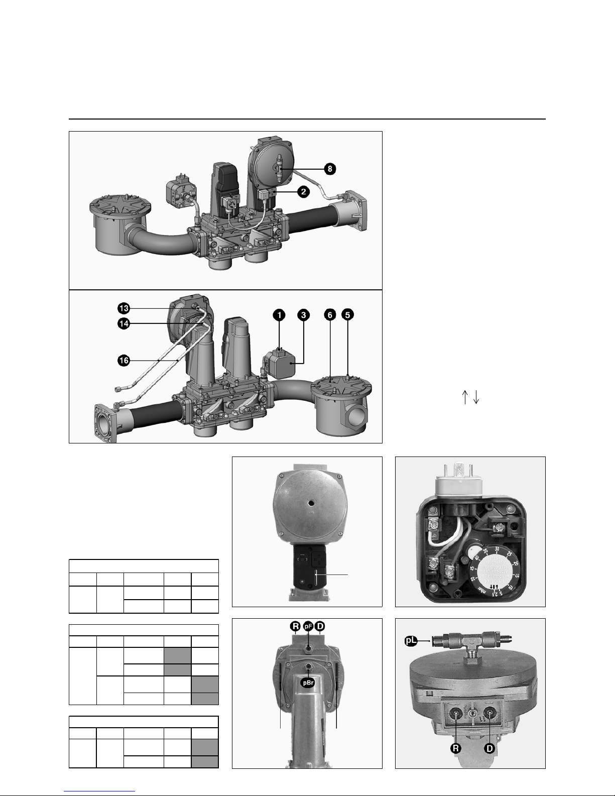
General information
Overwiew
Legend
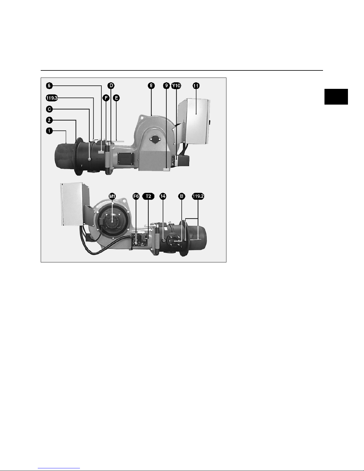
Legend
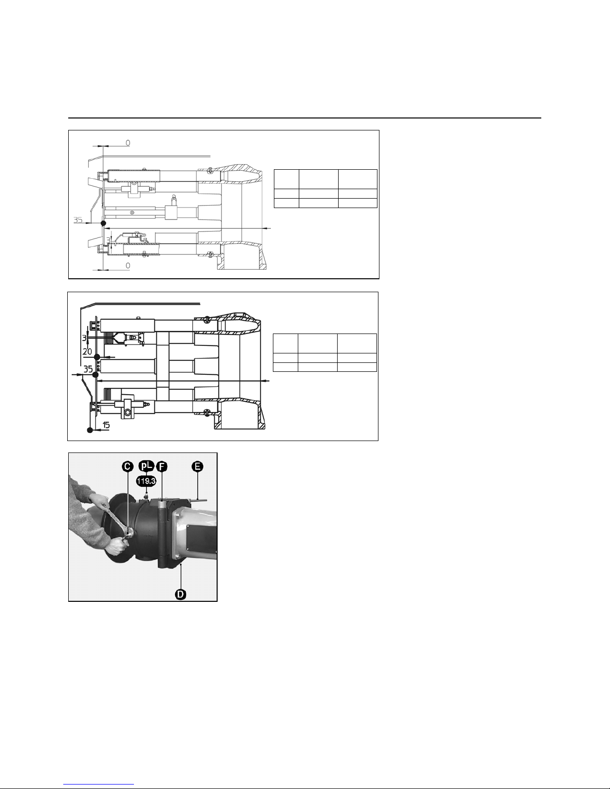
B Valve assembly connecting flange
C Gas supply line nut/bolt
E-F-D Mobile and fixed shafts and safety
screw
F6 Air pressure switch
M1 Fan motor
T Nozzle line
T2 Ignition transformer
Y10 Servomotor
1 Blast-tube
2 Space flange
5 Combustion head identification
plate
8 Case (burner body)
9 Burner body ID plate
11 Control unit
Control panel TC
14 Boiler sight glass ventilation air
pressure take-off
119.2 pF combustion chamber take-off
119.3 pL Pressure take-off L
en
Page 4

04/2009 - Art. Nr. 4200 1018 1100A4
General information
Packaging
Packaging
The burner is delivered on two pallets, in
three parcels, weighing on average 305
to 370 kg, depending on the model.
The burner of the body with :
- the built-in or detached electrical
cabinet. In those circumstances, a
connecting case is fitted on the burner
with the following inside :
- the operating instructions,
- the wiring and hydraulic diagrams of
the burner,
- the boiler house plate,
- the guarantee document,
The combustion head with :
- the burner front face seal, one bag of
bolts, two hinge pins.
The gas train with :
- a collector valve set,
- a bag o bolts, a PG21 support, rubber
gaskets, two tubes pF, one pipe pL, a
drawing, and a preassembled outside
filter.
Page 5
04/2009 - Art. Nr. 4200 1018 1100A 5
Installation
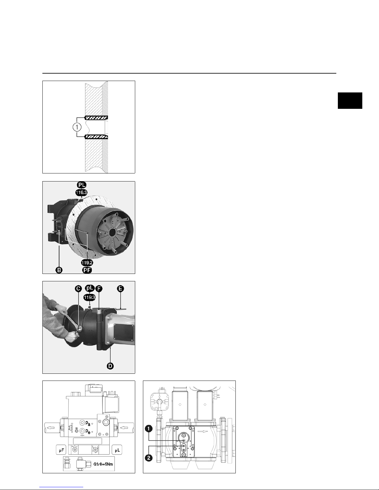
Assembly
Boiler face
• Prepare face following the enclosed
space requirement diagram.
• If required, insert face counter-plate
(optional)
• Fill in space 1 with recommended
heat-resistant material or material
supplied by the boiler manufacturer.
Chamber pressure take- off pF should
never be choked.
Combustion head
• Position combustion head, so that gas
train is horizontally connected on the
right.
• The other assembly positions are not
allowed.
• Fix and secure combustion head with
its gasket on boiler face.
• Check subsequently for leaks.
Gas train
• Check presence and position of gasket
on the flange of gas train B.
• Install support PG 21 (drawing)
• When fitting gas train, valve coils must
be in high vertical position.
Important
When using a left-mounted VGD gas
train, the SKP75 regulator should pivot
by 180°. To that end :
• Remove regulator SKP75.
• Remove connector (3P + T) on the
side of the regulator, and put it back
together on the opposite side.
Seal off the former position of the
connector.
• Reassemble the regulator after it has
pivoted by a half turn (180°).
Burner Body
• Hook burner body to combustion head
using fixed pin F located on the
opposite side of the gas train.
• Connect the ignition cables on both
transformers.
• Close the burner body with removable
pin E.
• Fix safety screw D.
Connecting the gas pressure take-offs
• Connect coupling pF of the valve to
the coupling labelled pF on the
combustion head with two reversible
preformed tubes (right - left) ,which
are connected up by a coupling (see
drawing).
• Crimp the rings on the tubes.
• Connect the coupling labelled pL to
the coupling pL of the valve.
• Tighten nut by hand.
• Check subsequently for leaks.
Fitting the leaks controller
VPS 504 S02
• Remove the two screws pa and pe on
valve MBVEF, and the two screws 1
and 2 on valve VGD.
• Make sure the two O-rings are
available on the VPS.
• Fasten the VPS with the 4 self-forming
screws
• Connect the cord of plug 7P according
to the electrical diagram.
• Connect plug 7P to the VPS.
• Check subsequently for leaks
Case of valve VGD20 : proceed as
indicated at the beginning of the earlier
paragraph, then :
• Fit the tubes and the terminal block
supplied.
• Fasten the VPS on the terminal block
using the 4 self-forming screws
supplied.
• Proceed afterwards as in earlier
paragraph.
en
Page 6

04/2009 - Art. Nr. 4200 1018 1100A6
Installation
Gas and electrical connections
Gas connection
Connecting the gas distribution system
to the gas train must be carried out by a
skilled technician.
The pipe section must be calculated, so
that load losses do not exceed 5% of
distribution pressure.
The external filter (ES08.2800) must be
fitted horizontally with a clean tube and
the cover placed in a vertical position to
allow for maintenance and to prevent
dust being carried along downstream of
the filter upon disassembly.
Any other type of assembly is
prohibited.
The ball valve (not supplied) must be
mounted upstream and as close as
possible to the external filter or to the
valve (pocket filter).
Threaded couplings used should comply
with current standards: tapered external
thread, parallel internal thread, with
tightness secured in the thread.
Enough space should be provided for
access to the setting of the gas pressure
switch.
Piping must be drained upstream of the
valve. Connections carried out in sit
must be tested for leaks using foam
designed for that purpose.
No leakage should be detected.
Electrical connection
Electrical fittings and connections
should comply with the current
standards.
Earth must be connected and tested.
See electrical diagram when connecting
the burner and the regulator.
The burner is supplied for a three-phase
electrical voltage 400V - 50Hz with
neutral and earth.
The ventilation motor starts up
automatically. A variable frequency
regulator can be fitted as an extra
option.
The three-phase operation 230V - 50Hz
requires : changing the coupling of the
motors and of the thermal relays of the
contactors (ES08.4000 and 5000), and
using a 630 VA insulation transformer on
the control circuit (not supplied).
For other voltages and frequencies,
please contact us.
Electrical connections
1) burner
- Built-in electrical cabinet
• Use stuffing boxes in order to secure
the required level of protection.
All the links, power and control, are
connected to the terminal block of the
cabinet.
Provide cables in sufficient length to
secure the gyration of the burner body
according to the assembly.
• Check and adjust the calibre of the
contractors and thermal relays and the
wires section according to the
characteristics of the motor and of the
available voltage.
Wiring is not supplied.
- Detached electrical cabinet:
That cabinet can be installed:
- either against a wall
- or on a floor-mounted sub-frame.
All the links, power and control are
connected between the cabinet terminal
block and the terminal block of the
coupling case on the burner body.
The other assembly conditions are
similar to those of the built-in cabinet
2) of the gas train
• Connect the plugs pending to the
valve:
- either on the control cabinet,
- or on the coupling case on the
burner body.
Page 7
04/2009 - Art. Nr. 4200 1018 1100A 7
Start up
Preliminary check-up and leakage tests
Adjusting air pressure switch
Burner start up simultaneously involves
starting up the installation by the fitter or
his representative; only they can
guarantee compliance of the boiler
house with currently accepted practices
and the regulations in force.
The fitter must first be in possession of a
"certificate of gas conformity" (fuel)
issued by either the approved body or
the distributor and also have leak-tested
and drained the pipework upstream from
the quarter-turn hand-operated valve.
Preliminary check-up
• Check the following:
- rated available voltage and electric
frequency and compare them with
the value showing on the
identification plate,
- polarity between phase and neutral,
- connection of the previously tested
earth wire,
- lack of potential between neutral and
earth,
- motors direction of rotation,
- thermal relays only in manual (H)
position with intensity adjustment.
• Cut off the power supply
• Make sure power is off
• Close fuel valves
• Read service instructions from boiler
and regulator manufacturers
• Check that :
- boiler is full of pressurized water
- circulator(s) is (are) working
- mixing valve(s) is (are) open
- combustible air supply to the boiler
and combustion products exhaust
pipe are actually operating and are
compatible with the rated capacity
of burner and fuels
- draught regulator is working properly
on the exhaust pipe
- protective fuses outside burner are
available, calibrated and adjusted
- boiler regulator circuit is adjusted.
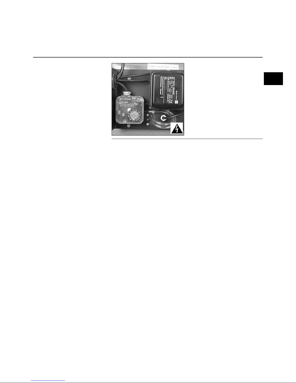
Gas pressure switch setting
• Remove the transparent cover.
The unit includes a index and a
graduated mobile disk.
• Provisionally set the pressure switch at
the minimum value shown on the
graduated disk.
Leakage test
• Connect a manometer on the pressure
nipple upstream from the gas train.
• Open and close the ball valve
• Check supply pressure and its longterm stability
• Use a specially designed foam product
to check tightness of gas train
connections, including external filter.
No leakage should be detected.
• Drain when necessary pipework
downstream from the ball valve
• Close drain valve, remove the
manometer and close the pressure
take-off.
en
Page 8
04/2009 - Art. Nr. 4200 1018 1100A8
Start-up
Checking and adjustments
Combustion implements and secondary air
Secondary air (dimension Y)
This is the amount of air flowing between
the tubulators diameter and blast-tube.
On delivery, dimension Y is set at 453 in
KN and 753 in KL.
However,
- this value can be adjusted according to
the following :
- gas firing quality (shock, vibration,
judder, time lag),
combustion quality for gas flows.
Setting
It is performed when burner is shutdown,
with removal of combustion implements,
following the procedure outlined in the
earlier section.
By increasing dimension Y, secondary
air reduces, the CO
2
increases and vice
versa.
• Loosen both screws from the
turbulator support.
• Slide the turbulator support into the
required direction.
• Measure dimension Y; tighten both
screws.
• Adjust the diffuser according to the
type of head and gas used following
the enclosed plan.
• Reassemble the whole unit.
• Make sure the flat gasket is available
and in position on the gas inlet line.
Natural gases -low NOx
Bold : factory settings
secondary
air
maxi
secondary
air
mini
KN Y=453 Y=478
KL Y=753 Y=778
Natural gases & propane
Bold : factory settings
secondary
air
maxi
secondary
air
mini
KN Y=453 Y=478
KL Y=753 Y=778
Checking and setting combustion
Burner is supplied already set for natural
gas.
• Remove the safety screw D.
• Remove the movable pin E.
• Open the body of the burner.
• Disconnect the two ignition cables on
the transformer and the ionization
sensor cable.
• Unscrew the nut and the lateral screw
C which immobilise the gas supply
line.
• Withdraw the combustion
components.
• Check the settings :
of the ignition electrodes, the
ionisation sensor, and of the diffusors
according to the gas available and the
accompanying diagrams.
• Check to ensure the presence and the
correct positioning of the sheet gasket
on the gas supply line.
• Re-assemble.
• Check :
- the tightness of the screw and the
nut C,
- subsequently for leaks.
Page 9
04/2009 - Art. Nr. 4200 1018 1100A 9
Start-up
Adjustments
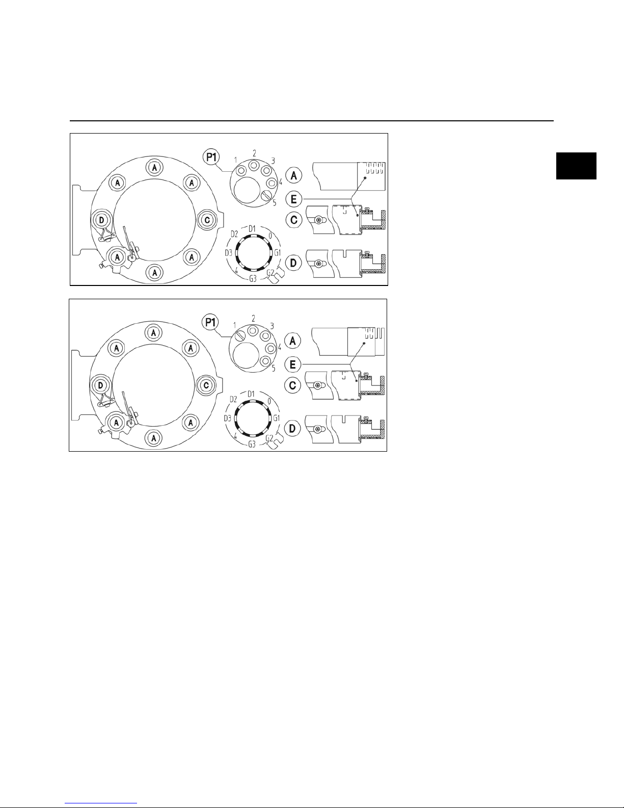
Diffusors and injectors
"G-VT-type" head adjustment for
Low NOx natural gas
Diffusors A:
- External slots fully closed
- Downstream injector pellet P1 with
screw in position 4 for ES08.2800 and
5 for ES08.3700 to 5000.
Diffusors C:
- Upstream slot closed
- Downstream injector with screw in
position G3 for ES08.2800 and G2 for
ES08.3700 to 5000.
Ignition diffusor D:
- Upstream slot open
- Downstream injector with screw in
position G2
Head F-VT adjustment for Low NOx
propane gas
Diffusors A:
- Upstream slots open
- Downstream injector pellet P1 with
screw in position 1
Diffusors C:
- Upstream slot closed
- Downstream injector with screw in
position G2
Ignition diffusor D:
- Upstream slot open
- Downstream injector with screw in
position G2
Natural gas Low NOx
G/F-VT
Propane gas Low NOx
G/F-VT
en
Page 10
04/2009 - Art. Nr. 4200 1018 1100A10
Start up
Description, settings
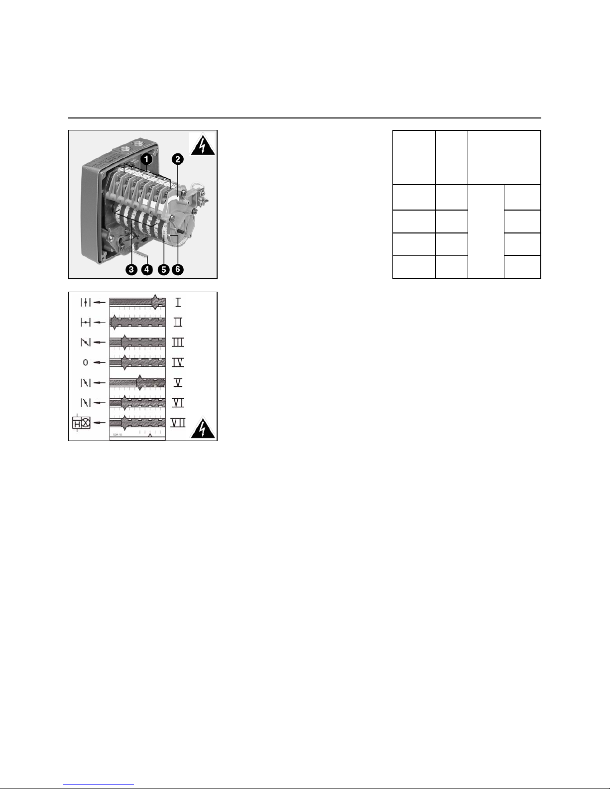
Combustion air
Servomotor Y10
1 Connection terminal board
2 Cam setting key
3 Seven adjustable graduated cams
4 Motor disengaging lever
5 No adjustable graduated cylinder
for servomotor position
6 Graduated cylinder index
SQM 10 16
Cam functions
Cam Function
I Nominal flow-rate
II Stop/0°
III Firing air flow-rate
IV Free 0°
V Cam V gives minimum regulation
info; must be set between values
of cam I and VI
VI Set minimum air flow-rate
VII Simultaneous switch-on of
nominal flow indicator and hour
counter (only for operation hours
below nominal flow rate)
• Set a few degrees below the
regulation flow-rate value of Cam
I.
Cam VI controls minimum automatic
flow-rate following ignition. If not
requested, the flow remains unchanged.
The time-delay unit K6 in the control
cabinet must be set at ≅ 15s.
Setting
• Remove cover.
• Check cam drum reset.
• Preset the cams according to boiler
capacity and the values shown in the
table below.
To do this:
• Adjust the cam either by hand or with
the key going along with the
servomotor. The angular position is
obtained in relation to each cam index.
Burner
power
kW
2100 33
2850 55
2250 50
3800 80
2400 55
4100 80
2800 55
4600 80
Air setting in °
i gnition nominal
cam III cam I
ES08.
2800
15
ES08.
3700
ES08.
4000
ES08.
5000
Page 11
04/2009 - Art. Nr. 4200 1018 1100A 11
Start up
Description and adjustment
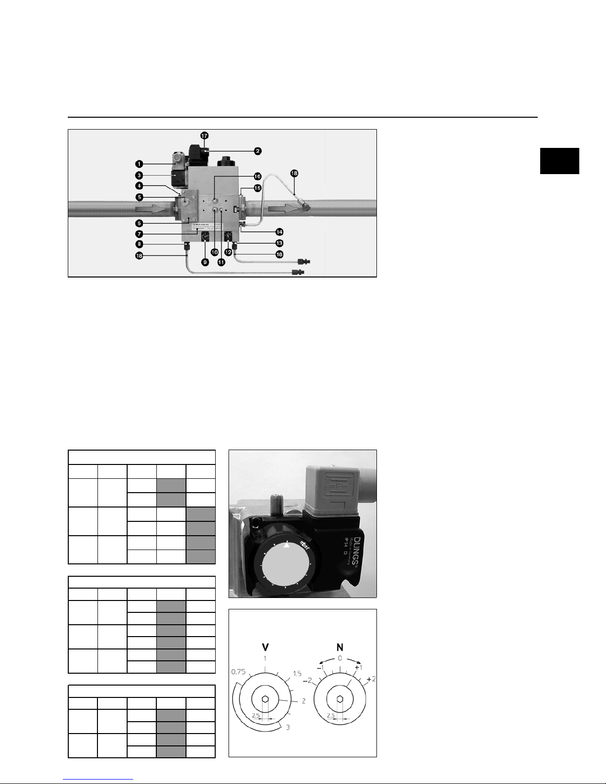
MB-VEF gas valve
1 Pressure switch electrical
connection (DIN 43650)
2 Solenoid electrical connection
(DIN 43650)
3 Pressure switch
4 Intake flange
5 Pressure take-off G 1/8 before
possible filter on either side
6 Filter under the cover
7 Identification plate
8 Air pressure pL G 1/8 connection
9 V ratio adjusting screw
10 Pressure take-off pe G 1/8 both
sides
11 Gas pressure take-off pBr
M4 (V2)
12 Adjusting screw for correction of
zero point N
13 Connection G 1/8 for combustion
chamber pressure pF
14 Connection G 1/8 for gas pressure
pBr
15 Outlet flange
16 Pressure pa take-off after V1 both
side
17 On indicator V1, V2 (optional)
18 pBr - pL - pF pressure take-off
tubes
MB VEF valve
MB VEF valve…is a compact assembly
including the following :
A built-in or pocket filter, adjustable
pressure switch, non-adjustable quickacting safety valve, proportional
regulator-controlled main valve which
can be adjusted on opening (V and N). It
ensures a constant gas flow/air flow ratio
and is quick-acting.
The regulator also takes into account
combustion chamber pF pressure or
atmospheric pressure.
The valve is delivered preset according
to table here below.
Air pressure switch setting
• Remove the transparent cover.
The unit includes a index and a
graduated mobile disk.
• Provisionally set the pressure switch at
the minimum value shown on the
graduated disk.
Regulator setting
All settings are carried out with the
burner working:
• Use 2,5mm hex key to turn the 2
screws.
- Screw V gives the gas/air ratio,
graduated 0,75 to 3,0.
- Screw N is used to adjust air excess,
graduated - 2 to + 2.
ES08.2800 G/F-VT
Gas
P
VEF 412 42
0
V
3
N
0
V
3
N
0
V
3
N
0
ES08.3700 G/F-VT
Gas
P
VEF 412 42
0
V
3
N
0
V
3
N
0
V
3
N
0
ES08.4000/5000 G/F-VT
Gas
P
VEF 412 42
0
V
3
N
0
V
3
N
0
G20 1 50
G20 3 00
G25 3 00
G20 1 50
G20 3 00
G25 3 00
G20 3 00
G25 3 00
en
Page 12
04/2009 - Art. Nr. 4200 1018 1100A12
Start-up
Description and settings
VGD gas valve
SKP75 regulator
1 Pressure switch electrical
connection (DIN 43650)
2 Solenoid electrical connection
(DIN 43650)
3 Pressure switch
4 Intake flange
5 Pressure take-off G 1/8 before the
filter
6 External filter DN65
7 Identification plate
8 Air pressure pL G 1/8 connection
9 Adjusting screw R of gas flow/air
flow ratio
12 Adjusting screw D for correcting
zero point
13 Connection G 1/8 for combustion
chamber pressure pF
14 Connection G 1/8 for gas
pressure pBr
15 Outlet flange
16 pBr - pL - pF pressure take-off
pipes
Setting gas pressure switch
• Remove transparent cover.
Unit includes a | index and a
movable graduated disk.
• Provisionally set the pressure
switch at the minimum value
shown on the graduated disk.
Gas valve
opening
indicator
R ratio
indicator
D value
indicator
The VGD valve associated with
SKP75 regulator ensures a constant
gas flow/air flow ratio and is quickacting. The regulator also takes into
account combustion chamber pF
pressure.
The valve is delivered preset according
to table here below.
ES08.2800 G/F-VT
Gas P 40.06
5
40.08
0
(Scr. R)1 2
(Scr.
D
)2 1,4
ES08.3700 G/F-VT
Gas P 40.06
5
40.08
0
(Scr. R)2
(Scr.
D
)1,4
(Scr.
R
)1
(Scr.
D
)2
ES08.4000/5000 G/F-VT
Gas P 40.06
5
40.08
0
(Scr. R)1
(Scr.
D
)2
G20 150
G20
40
150
VGD
VGD
G20 20 - 40
VGD
Page 13

04/2009 - Art. Nr. 4200 1018 1100A 13
Start-up
Description of adjustments
Gas valve / leakage controller
Leakage controller VPS 504 S02
Optional for ES08.2800
Operating principle :
Prior to each start-up of burner, the
control unit shall check subsequently for
leaks between safety and main valves
by increasing the distribution pressure.
Electrically, the leakage controller gets
connected serially between the
thermostatic circuit and the control and
safety unit of the burner.
Installation :
Directly on valve.
Program development :
At shutdown, safety and main valves are
closed.
At thermostatic shutdown, the leakage
controller is powered up and the booster
increases distribution pressure by
20mbar.
After no more than 30 seconds of
operation :
- If leakage test is validated, the yellow
light comes on and power is released
to feed the control and safety unit,
which starts its cycle.
- If leakage test is not validated, the red
light comes on and the control and
safety unit is not powered up.
- Control cycles need to be restarted
manually. If fault persists, valve
should be changed.
Adjustment :
The leakage controller requires no onsite adjustment.
Operating test :
While leakage controller is working :
• Open pressure take-off pa. The
leakage so generated prevents the
super pressure from building up, and
the safety unit locks on after
30 seconds.
• Close pressure take-off pa.
• Release controller safety by pressing
the red indicator light.
The leakage controller restarts and, after
30 seconds, the yellow indicator lights
up and powers up the control and safety
unit, which begins its cycle.
1 Wieland 7P socket
3 Filter element
4 O-ring Ø 10.5 x 2.25
5 Fuse Y 6.3 250V Ø 5 x 20
6 Yellow indicator On :
Leakage test validated
7 Red indicator On :
Leakage test not validated,
manual release
8 Spare fuses magazine
9 pa (p2) pressure take- off Ø 9.
Test pressure : pe + 20mbar
10 Pressure take- off : pe (p1) Ø 9.
Inlet pressure (distribution)
en
Page 14
04/2009 - Art. Nr. 4200 1018 1100A14
Start up
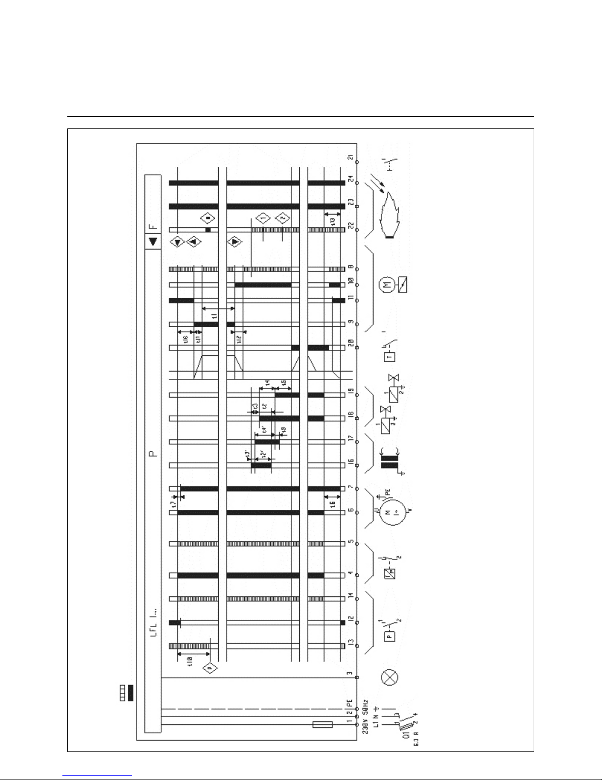
LFL 1.333 Control and safety unit
Required input signals
Output signals
Reset Trouble Pressure switch Limiter Burner motor Ignition transfo. Oil valve Regulator Servo motor Flame Reset
t1 Pre ventilation time with open air flap
t2 Safety time
t2’ Safety time or 1st safety time for burner with driver
t3 Short pre-ignition time (transformer terminal 16)
t3’ Long pre-ignition time (transformer terminal 15)
t4 Interval between voltage at terminal 18 (t2 start) and 19 (BV1-BV2)
t4’ Interval between t2’ start and 19 (BV2)
t5 Interval between voltage at terminal 19 and 20 (BV-Regul.)
t6 Post-ventilation time (with M2)
t7 Interval between start order and voltage in 7
t10 Interval between start and air pressure monitoring without flap movement time
t11 OPEN position air flap movement time
t12 MINI position air flap movement time
t13 Accepted post combustion time
t16 Interval until air flap opening order.
Page 15

04/2009 - Art. Nr. 4200 1018 1100A 15
Start-up
LFL 1.333 control unit program
LFL 1.333 control unit program
t1 : Pre ventilation time 30s
t2 : 1st safety time 3s
t3 : Pre-ignition time 6s
- Safety time following
flame disappearance < 1s
Safety unit operation
The control and safety unit LAL 2.25 is
designed for intermittent service,
(limiting it to twenty-four hours of
continued use).
For convenience sake, the function
diagram does not include all electrical
components.
It is assumed that :
- Power supply is compliant
- Pressure switches and servomotor
cams have been preset correctly.
Commands from
control and safety unit
Required input signals
Terminal numbers are those shown on
the control and safety unit base.
Each unit program sequence is shown
by a visible symbol on the rotating disk,
near reset button.
Program operating sequences :
Motor switched on (terminal 6)
when :
- main voltage is applied to
terminal 1,
- air flap is closed : voltage at
terminal 11 is applied to
terminal 8,
- air pressure switch is off : voltage
at terminal 12 is applied to
terminal 4,
- limit and safety thermostats and
min. gas pressure switch are off:
voltage at terminal 4 is applied to
terminal 5.
Servomotor control (cam I) is wide
open (terminal 9) and opening
confirmed (terminal 8) : start of
pre ventilation.
Start of permanent air pressure
monitoring by air pressure switch
and confirmation at terminal 14.
Circuit broken between terminals 4
and 13.
Servomotor control (cam III) in
ignition position (terminal 10) and
position confirmed (terminal 8).
Start of pre-ignition (terminal 16)
Simultaneous opening of safety
valve and main valve (terminal 18)
: start of safety time.
Start of continuous monitoring of flame
presence.
Ignition transformer off, shortly
followed by end of safety time.
Power regulation enable
(terminal 20) :
Burner stoppage via limit
thermostat cutoff, then servomotor
control off (cam II).
Important :
in continual functioning, a
thermostatic cut-out is obligatory
after twenty-four hours.
en
Page 16
04/2009 - Art. Nr. 4200 1018 1100A16
Start-up
Description of functions
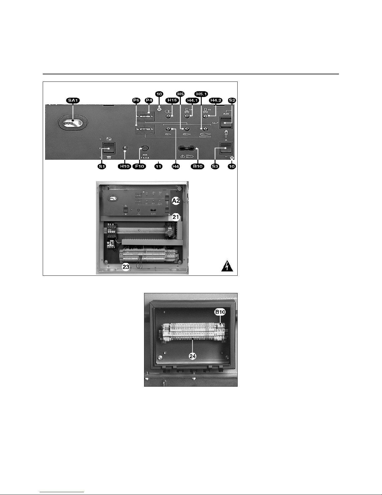
Control panel TC
TC
Description of TC functions
(Control Panel)
A2 Standardized 48x48 or
48x96mm power regulator
positions (option)
B10 Measuring bridge [µA DC],
ionization current
F10 Control panel fuse TC
Green indicators
H4 Ignition load
H4.1 Safety valve
H4.2 Main valve
H5 Minimum control flow
H5.1 Nominal flow
H10 Control Panel (TC) energized
H15 Transformer
P4 Hourly totalizer counter
P5 Nominal flow hourly counter
Three position switch :
S1 General switch of TC
0 Off
1& Local mode
1> Remote control mode
S2 Choice of power setting
' Manual mode with S3
Auto Automatic mode with
S1&
S3 Pulse with S2'
+/- Power increase/decrease
SA1 The control unit displays :
- the program
- faults : red indicator illuminated
and reset button
10 Two screws to be removed for
access to the control unit and to
option positions
11 On the underside of the control
panel (TC), remove two screws
10 and switch to DIN 35mm rail
and terminals for options
21 Rating plate
23 Movable plate for the cable
glands
Electrical cabinet on burner
The electrical cabinet holds all the
required components for the operation
of the device. The access door, which
can be locked, is fitted with a window
displaying the control panel TC, signals
and, inside, a magazine containing the
literature.
In the lower part, there is a removable
plate with the various stuffing boxes.
Thanks to such cabinet with easy
access, it is possible to install various
options :
- A built-in power regulator in a
standardized space requirement of 48
x 48 or 48 x 96 mm.
- Relays for data transmission to be
fitted on a 35 mm DIN rail ,in
abeyance under the control panel
(remove two screws 10 and tip out).
Coupling case on burner
Option for cabinet outside burner
B10 Measuring bridge [µ A DC]
cell current
24 Link terminals between burner
and electrical control cabinet
Page 17

04/2009 - Art. Nr. 4200 1018 1100A 17
Start up
Working cycle test
Firing
Safety unit settings and checks
Cycle functioning test
• Open and then shut the quarter-turn
manual fuel valve.
• Charge the burner.
• In the TC of the electric control box
select the manual operation mode
S1& - S2'.
• Close the thermostatic circuit.
The leak tightness test device VPS 504
S02 is charged. After 30s if the test is
validated ; the yellow light will shine. The
control and safety unit is supplied with a
voltage; the red light of the unit will
shine.
• Reset the control and safety unit and
check that it is working correctly.
The program should function in the
following way :
- air flap totally open,
- initial blower time 30s,
- return to ignition position,
- ignition of electrodes for 6s,
- opening of the valves,
- closing of the valves after a maximum
of 3s after they were opened,
- the burner will stop functioning due to
a lack of gas pressure or due to
resetting of the control and safety unit
due to the disappearance of the flame.
In case of doubt, perform the test
previously described.
It is only after this very important
program test phase that the burner can
be fired.
Firing
Warning :
Firing should only take place when all
the conditions set out in the previous
chapters have been adhered to.
• Connect a microammeter scale (0100µA DC), instead of the measuring
bridge located on the TC.
• Open the quarter-turn manual valve of
the fuel.
• Close the thermostatic circuit.
The leak tester is charged. At the end of
the test (30s), the unit is charged.
• Reset the control and safety unit.
The burner will be working.
- Check :
- the combustion process once the
flame has appeared,
- the overall leak tightness of the gas
train.
There should not be any leakage.
• Read the current of ionization (a value
between 20 and 80µA).
• Measure the gas flow shown on the
counter.
• Raise the power to its nominal output
by activating the switch intermittently
S3+.
• Test the combustion.
Observe the waste gas temperature
recommended by the boiler
manufacturer to obtain the required
useful output.
According to the combustion tests,
adjust the burner while in operation to
the nominal output on the screw V of the
MB VEF valve (R for the Skp regulator).
• To increase the CO
2
rate, increase the
ratio (decreasing the ratio will have the
opposite effect).
• Read the current of ionization (a value
between 20 and 80µA).
• Measure the gas output on the
counter.
• Increase or reduce the power by
increasing or reducing the value read
from the graduated vessel of the
cam I.
• Stop and then start the burner up
again.
• Check the combustion process once
the flame has appeared.
According to the measured values,
adjust the burner while in operation on
the screw N of the MB VEF valve (D for
the SKP regulator).
• If necessary, adjust the cam value III
for ignition and the cam VI for
minimum control.
The adjusting procedure is identical to
that of the cam adjustment I.
• Increase the power back up to the
nominal output and check the
combustion.
If the value has been changed by the
action performed on the screw N (D
for the SKP regulator); adjust the ratio
V (R for the SKP regulator) as
required.
• Optimize combustion results by
adjusting :
- the setting of the secondary air (Y
dimension) following the procedure
described in the chapter : “Setting
combustion components and
secondary air ”;
• Increase the Y dimension, the CO
2
rate rises and this process can occur
inversely.
A modification made to the Y dimension
can necessitate a correction of the air
flow rate.
• Test the combustion.
Assess burner operation : on ignition,
and when power is increased and
decreased.
• Check, while the burner is functioning,
and by using a foaming liquid product
that is specially designed for this
purpose, the leak tightness of the gas
train connections.
There should not be any leakage.
• Test the safety devices.
Setting safety test devices
Gas pressure
• Set at the minimum distribution
pressure.
Burner is working with ignition flow.
• Close the quarter-turn manual valve of
the fuel slowly.
The burner should stop functioning
owing to a lack of gas pressure.
• Re-open the quarter-turn manual
valve.
The burner will start up again
automatically.
The pressure switch is set.
• Fix and screw on the housing.
Air pressure switch.
Burner is working with ignition flow.
• Locate the switch’s cut-off point (lock).
• Multiply the value by 0.8 to obtain the
setting point.
• Restart the burner.
• Progressively obstruct the aspirating
port on the motor-driven blower unit.
• Check that the CO rate is still inferior
to 10, 000ppm before resetting the
control unit.
If not, increase the air pressure switch
setting and repeat the test.
Leak testing device tester VPS :
• Open pa on the device.
• Restart the burner.
After 30s the device is safe (red light
illuminated).
• Close pa.
• Reset the leak tightness tester’s safety
device by pressing the red indicator.
The test cycle is relaunched.
The burner is operational.
• Check for leaks.
• Disconnect the two cables of the
microammeter simultaneously.
The unit should reset itself immediately.
• Replace the measuring bridge, the
housings.
• Disconnect the measurement devices.
• Re-close the pressure connectors.
• Reset the unit.
The burner will be working.
• Check :
- the absence of leaks between the
flange and the boiler front,
- opening of regulator (limiter and
safety) circuit,
- intensity of thermal relays of the
motor-driven blower unit according
to the manufacturer’s instructions.
• Check combustion under actual
operating conditions (doors closed,
etc) and absence of leaks in the
different systems.
• Note the results on the appropriate
documents and communicate them to
the dealer.
• Start-up automatic operation.
• Distribute the information required to
operate the boiler.
• Place the boiler-room plate where it
can be easily seen.
en
Page 18

04/2009 - Art. Nr. 4200 1018 1100A18
Maintenance
Important
Maintenance operation should be
carried out regularly, at least once a year
and by qualified personnel.
• Cut off power at the multi pole switch.
• Make sure there is no current.
• Close the fuel intake.
• Check for leaks;
Setting values are those indicated in
section Start up.
Use only genuine manufacturer spare
parts.
Removing the blast-tube.
This operation requires :
- either the opening of the burner body
and the boiler door,
- or removal of the burner.
1) Access via boiler door: Proceed as
indicated at the start of the previous
paragraph, up to "Withdraw the
combustion components". Then…
• Unscrew the three blast-tube screws
from the inside.
• Change blast-tube.
• If necessary, fill space between the
quarl and blast-tube with refractory
material.
Do not block pressure take-off pF.
• Re-assemble.
2) Removing burner :
Proceed as indicated at the start of the
previous paragraph, up to "Withdraw
the combustion components". Then…
• Remove hoses, burner body, gas train
and combustion head.
• Unscrew the three blast-tube screws
from the inside.
• Change blast-tube and front seal.
• Re-assemble.
Cleaning air circuit
Depending on intensity and conditions
of operation of the burner :
• Clean the air stream circuit, the fan,
the flap and the burner body.
• Reassemble unit..
• Check the direction of rotation of the
ventilating motor.
Checking gas filter
The external or valve filter (integrated or
pocket) must be examined at least once
a year and filter element changed if
filthy.
• Remove cover screws.
• Remove filter element. Make sure no
dirt is left in its cover.
• Install a new, similar element.
• Replace seal, cover and screws.
• Open ball valve.
• Check tightness.
• Check combustion.
Leakage controller
• Remove leakage controller.
• Check or replace filter elements
located on pe and pa.
• Reassemble unit.
• Check working order and for any
possible leaks.
Gas valves
These valves do not require any special
maintenance. The valves must not be
repaired. Defective valves must be
replaced by a qualified specialist, who
will then carry out new check-up for
leaks, correct running and combustion.
Checking connections
In the electric control cabinet, on the
connecting terminal block, the
servomotor, the motor-pump unit, the
ventilation motor
• Check that wiring is fully tight to all
terminals.
Note
• Check combustion under actual
operating conditions (doors closed,
etc), and absence of leaks in the
different systems.
• Carry out the safety checks.
• Note the results in the appropriate
documents.
Checking the combustion
components
• Remove the electric plugs and
pressure tapping on the gas train.
• Remove both fuel oil tubes and both
Remove the safety screw D.
• Remove the movable pin E.
• Open the body of the burner.
• Disconnect the two ignition cables on
the transformer and the ionization
sensor cable.
• Unscrew the nut and the lateral screw
C which immobilise the gas supply
ligne.
• Take out the combustion components.
• Clean thoroughly.
• Check the condition and the settings :
of the baffle, the ignition electrodes,
the ionisation sensor, the diffusors,
the ignition cables and the ionization
cable.
• Change any defective parts.
• Check to ensure the presence and the
correct positioning of the sheet gasket
on the gas supply ligne.
• Re-assemble.
• Check the tightness of the screw and
the nut C.
Page 19

04/2009 - Art. Nr. 4200 1018 1100A 19
Troubleshooting
Symbols
Fault Causes Corrective action
Burner stopped in service position
nothing happens.
Insufficient gas pressure. Set the distribution pressure.
Clean filter.
Gas pressure normal. Gas pressure switch set wrongly or
defective.
Air pressure switch closed (contact
welded).
Set or replace gas pressure switch.
Replace air pressure switch.
With leak testing device. Leaker test shutdown.
Leaker test not energized.
Unscrew or change valve.
Check, change fuse.
Burner shut down
in service position.
Parasitic flame on thermostatic cut-out. Check gas valves for leaks.
Put to post-ventilation.
P In “P” position.
Motor not running. Protection device open Insufficient air pressure.
Thermal relay tripped.
Protective device defective.
Replace air pressure switch.
Reset, adjust or replace the thermal relay.
Replace protection device.
Motor not running
Protection device closed.
Cable between protection device and
motor defective.
Motor defective.
Check cables.
Replace motor.
1
Motor running.
in service position.
In “1” position.
Air pressure switch wrongly set or
defective.
Fault in flame monitoring system.
Adjust or replace air pressure switch.
Check pressure pipes.
Check the position of the ionization sensor
according to the earth.
Replace the control and safety unit.
No ignition spark. Ignition electrode(s) short-circuited.
Ignition cable(s) perished.
Ignition transformer defective.
Set or replace electrodes.
Replace ignition cables.
Replace ignition transformer.
Control and safety unit. Replace control unit.
Magnetic valves do not open. Break in electrical connections. Check cables between control unit,
servomotor, and the valve.
Coil(s) short-circuited. Replace coil(s).
Mechanical jamming of valves or
proportion regulator.
Replace the valve.
Combustion head Combustion head wrongly set. Set combustion head.
Flame appears, but pulsates or goes out
(insufficient ionization current).
Air flap open too wide and/or gas flow too
great.
Set air flap and/or gas flow.
I
Burner continues with blower on but no
flame
In “I” position.
on
or
on
Servomotor defective.
Air flap jammed
Mechanical coupling defective.
Set or replace servomotor.
Free air flap.
Check or replace coupling.
Others faults.
Fault shutdown at any time with no
program symbol.
Premature flame signal.
Ionization sensor rusted.
Replace the control and safety unit.
Replace the sensor.
Reprogramming of control and safety unit
without fault shutdown.
Gas pressure switch set wrongly or
defective.
Set or replace gas pressure switch.
Check the following if failure
occurs :
• power supply (power and control),
• gas supply (valve pressure and
opening),
• control components,
• switch positions on TC control panel.
If problem persists :
• Check various program symbols
described here below on the control
and safety unit.
All the safety components must not be
repaired but only replaced by identical
components.
Use only the manufacturer’s
original parts.
Note
After each operation :
• Check combustion and all circuits for
possible leaks.
• Perform safety check-up.
• Record results in the relevant
documents.
en
Page 20

04/2009 - Art. Nr. 4200 1018 1100A20
Informations générales
Sommaire
Garantie, sécurité
Principaux textes réglementaires
Inhaltsverzeichnis
Allgemeine Angaben
Gewährleistung, Sicherheit ..............20
Grundsätzliche Bestimmungen ........ 20
Gesamtansicht, Legende ................. 21
Lieferumfang ....................................22
Technische Angaben
Siehe technische Daten
Nr 420010180900
Installation
Montage ...........................................23
Gasversorgung.................................24
Stromversorgung.............................. 24
Inbetriebnahme
Prüfung vor Inbetriebnahme............. 25
Einstellungen...............................25-31
Programm des
Feuerungsautomaten .................. 32-33
TC-Bedienfeld ..................................34
Einstellung, Kontrolle Sicherheitsein-
richtungen.........................................35
Zündung ...........................................35
Wartung ...........................................36
Störungsbeseitigung .....................37
Gewährleistung
Montage und Inbetriebnahme müssen
sachgemäß durch einen Techniker ausgeführt werden. Die geltenden
Vorschriften sowie die in dieser Dokumentation gegebenen Anleitungen sind
verbindlich. Bei selbst teilweiser Nichteinhaltung dieser Bestimmungen kann
der Hersteller keine Haftung übernehmen.
Siehe ebenfalls :
- den dem Brenner beiliegenden
Garantieschein,
- die allgemeinen Verkaufsbedingungen.
Sicherheit
Der Brenner ist auf einem Wärmeerzeuger zu installieren, welcher an
betriebsfähige Auslassrohre der Verbrennungsprodukte angeschlossen ist.
Sein Einsatz ist in einem Raum vorzusehen, welcher seine Versorgung mit Verbrennungsluft und eine Ableitung
eventueller Schadstoffe erlaubt.
Der Kamin muss in Übereinstimmung
mit den geltenden Bestimmungen und
Normen dimensioniert und an die Verbrennungsstoffe angepasst werden.
Der Feuerungsautomat sowie die zur
Anwendung kommenden Abschaltvorrichtungen benötigen eine Stromversorgung 230 VAC % 50Hz
±1%
.
Ferner muss der Nullleiter über das
gleiche elektrische Potential wie der
Schutzleiter verfügen.
Der Brenner soll vom Stromnetz mittels
einer allpoligen Trennvorrichtung
gemäß den geltenden Normen isoliert
werden können.
Für die korrekte Funktion des
Brenners ist bei Anschluss des
7-poligen Steckers auf den polrichtigen Anschluss der Leiter zu achten.
Das Service-Personal muss alle
Arbeiten mit gröbster Vorsicht vornehmen, um jeglichen direkten Kontakt mit
nicht wärmeisolierten Zonen und Stromkreisen zu vermeiden. Wasserspritzer
auf die elektrischen Teile des Brenners
sind zu vermeiden.
Bei Überschwemmung, Feuer, Brennstoffauslauf oder anormalem Betrieb
(Geruch, verdächtige Geräusche usw.)
muss der Brenner abgeschaltet, die
Hauptstromversorgung und die Brennstoffversorgung unterbrochen und ein
Techniker gerufen werden.
Die Feuerräume, ihr Zubehör, die
Rauchabzüge und Anschlussrohre
müssen mindestens einmal jährlich und
vor der Inbetriebnahme des Brenners
gewartet, gereinigt und von Ruß befreit
werden.
Man beziehe sich hierzu auf die entsprechenden geltenden Bestimmungen.
Grundsätzliche Bestimmungen "FR"
Wohngebäude :
- Verordnung vom 2. August 1977 mit
den nachträglichen Ergänzungen und
Änderungen : Technische und
sicherheitsrelevante Vorschriften für
Brenngas- und Flüssigkohlenwasserstoffanlagen in Wohngebäuden
und deren Nebengebäuden.
- Norm DTU 64.4 - Technische
Vorschriften für Heizungsanlagen
- Norm NF C 15-100 - Elektrische
Niederspannung + Regeln
- Gesundheitsamtliche Vorschrift des
Departements
Gebäude mit Öffentlichkeitsverkehr :
- Sicherheitsvorschrift gegen Brand und
Panik in Gebäuden mit Öffentlichkeitsverkehr :
Allgemeine Bestimmungen :
- Artikel GZ (Brenngas- und Flüssigkohlenwasserstoffanlagen) ;
- Artikel CH (Heizung, Belüftung,
Kühlung, Klimatisierung und Herstellung von sanitärem Dampf und Heisswasser) ;
Sonderbestimmungen für die jeweilige
Art von Gebäuden mit Öffentlichkeitsverkehr.
Außerhalb "FR"
Berücksichtigen Sie örtliche Normen.
+
10
- 15
Page 21

04/2009 - Art. Nr. 4200 1018 1100A 21
Allgemeine Angaben
Gesamtansicht, Legende
Legende
B Anschlussflansch der Gasarmatur
C Schraube mit Mutter zur Befesti-
gung der Gaszufuhrleitung
E-F-D Achsen, beweglich, fest und für
die Sicherungsschraube
F6 Luftdruckwächter
M1 Gebläsemotor
T2 Zündtransformator
Y10 Stellmotor
1 Flammrohr
2 Abstandsflansch
5 Typenschild des Brennkopfs
8 Gehäuse (Brennergehäuse)
9 Typenschild des Brennkopfes
11 Schaltschrank mit Bedienfeld TC
14 Luftdruckabnahme zum Belüften
der Luke des Heizkessels
119.2 Druckabnahme Feuerraum pF
119.3 Luftdruckabnahme pL
de
Page 22

04/2009 - Art. Nr. 4200 1018 1100A22
Technische Angaben
Lieferumfang
Lieferumfang
Er besteht aus drei Paketen auf zwei
Paletten mit einem Gesamtgewicht von
305 bis 370 kg je nach Modell.
Das Brennergehäuse mit :
- Integriertem oder getrenntem Schaltschrank. In diesem Fall ist ein
Anschlusskasten auf den Brenner
montiert, der folgendes enthält :
- Betriebsanleitung
- Strom- und Hydraulikpläne des
Brenners
- Heiztafel
- Garantieschein.
Der Brennkopf mit :
- Kesselfassadendichtung, Zubehörbeutel, zwei Scharnierachsen.
Die Gasarmatur mit :
- Ventilen und Sammelrohr
- Zubehörbeutel, Halterung PG 21,
flachen Gummidichtungen, zwei
Rohren pF, ein Rohr pL, einer Zeichnung,
- einem vormontierten Außenfilter.
Page 23

04/2009 - Art. Nr. 4200 1018 1100A 23
Installation
Montage
Heizkesselfassade
• Die Fassade entsprechend dem beiliegenden Raumplan vorbereiten.
• Falls nötig, eine Fassadengegenplatte
anbringen (Option).
• Den Zwischenraum 1 mit einem vom
Kesselhersteller empfohlenen oder
gelieferten feuerfesten Material auskleiden.
Dabei nicht die Feuerraumdruck-
abnahme pF verstopfen.
Brennkopf
• Brennkopf so lagern, dass die Gasarmatur rechts waagrecht angeschlossen wird.
• Es sind keine anderen Einbaulagen
zulässig.
• Brennkopf mit seiner Dichtung auf der
Kesselfassade montieren und befestigen.
• Später auf Dichtheit prüfen.
Gasarmatur
• Vorhandensein und Einbaulage der
Dichtung im Flansch des Gasrohres B
prüfen.
• Halterung PG 21 (Zeichnung) einsetzen.
• Gasarmatur so befestigen, dass sich
die Magnetspulen der Ventile
unbedingt in oberer senkrechter
Lage befinden.
Wichtig
Mit nach links montierter Gasarmatur
VGD, muß der SKP-Regler um 180°
gedreht werden. Dafür :
• SKP-Regler demontieren.
• Die sich auf der Seite des Reglers
befindliche Buchse (3P+T) demontieren, und auf der anderen Seite montieren.
Alte Stelle der Buchse verstopfen.
• SKP-Regler nach halber Umdrehung
(180°) wieder montieren.
Brennergehäuse
• Brennergehäuse mit dem der Gasarmatur gegenüberliegenden festen
Achsbolzen F auf dem Brennkopf einhängen.
• Die Zündkabel an Trafo anschließen.
• Brennergehäuse mit dem beweglichen
Achsbolzen E schließen.
• Sicherungsschraube D einsetzen.
Anschluss der Gasdruck abnahmen
• Den Anschluss pF des Ventils mit dem
mit pF bezeichneten Anschluss am
Brennkopf mit zwei vorgeformten
umkehrbaren Rohren (rechts - links)
verbinden, die über einen Anschluss
miteinander gekoppelt sind (siehe
Zeichnung).
• Die Ringe auf den Rohren vor bördeln.
• Das mit pL bezeichnete Rohr mit dem
Anschluss pL des Ventils verbinden.
• Die Mutter von Hand festziehen.
• Später auf Dichtheit prüfen.
Montage des Dichtheitskontrollgeräts
VPS 504 S02
• Am Absperrschieber MBVEF die
beiden Schrauben pa und pe, am
Absperrschieber VGD die beiden
Schrauben 1 und 2 abmontieren.
• Prüfen, dass am VPS zwei Dichtungsringe vorhanden sind.
• VPS mit den vier mitgelieferten, selbstbohrenden Schrauben befestigen.
• Das Kabel von Anschluss 7 P gemäß
Schaltplan anschließen.
• Anschluss 7 P am VPS anschließen.
• Die Dichtheit später kontrollieren.
Ventil VGD20: Wie am Anfang von
Absatz oben beschrieben vorgehen,
dann:
• Die mitgelieferten Rohre und den
Anschlussblock montieren.
• VPS mit den 4 mitgelieferten selbstbohrenden Schrauben am Anschlussblock befestigen.
• Anschließend vorgehen, wie in Absatz
oben beschrieben.
de
Page 24

04/2009 - Art. Nr. 4200 1018 1100A24
Installation
Gas- und Stromversorgung
Gasversorgung
Der Anschluss der Gasarmatur an das
Gas netz darf nur von einem Fachmann
ausgeführt werden.
Der Gasleitungsquerschnitt muss so
gewählt werden, dass die Druckverluste
5 % des Netzdrucks nicht überschreiten.
Das externe Gas Filter (ES08.2800)
muss mit einem eigenen Stutzen
waagrecht auf dem Ventil angebracht
werden, wobei der Deckel für die
Wartung senkrecht stehen soll.
Es ist keine andere Einbaulage
zulässig.
Das externe Gasfilter muss mit einem
eigenen Stutzen waagrecht auf dem
Ventil angebracht werden, wobei der
Deckel für die Wartung senkrecht
stehen soll. Es ist keine andere Einbaulage zulässig.
Der (nicht mitgelieferte) Gaskugelhahn
ist vor dem externen Gasfilter oder dem
Ventil (Taschenfilter) und so nahe wie
möglich an demselben einzubauen.
Die Gewinde der benutzten Schraubverbindungen müssen den geltenden
Normen entsprechen, und zwar ein
konisches Aus engewinde und ein zylindrisches Innengewinde mit Gewindedichtung.
Es ist genügend Platz vorzusehen, um
den Zugang zur Einstellung der Gasdruckwächter zu ermöglichen.
Die Gasleitung ist vor dem Kugelhahn
zu entlüften. Alle an Ort und Stelle hergestellten Verbindungen müssen mit
einem hierzu geeigneten Schäummittel
auf Dichtheit überprüft werden.
Dabei darf kein Leck festgestellt
werden.
Stromversorgung
Die elektrische Anlage und die
Anschlüsse müssen entsprechend den
geltenden Normen ausgeführt werden.
Die Erdung muss angeschlossen und
getestet sein.
Für den Anschluss des Brenners und
der Regelung ist dem Schaltbild zu
folgen.
Der Brenner wird für Drehstrom von
400 V - 50 Hz mit Null-Leiter und Erde
geliefert.
Der Gebläsemotor startet im Direktanlauf.
Die Installation eines Frequenzwandlers
ist in Option möglich.
Ein Betrieb mit 230 V - 50 Hz Drehstrom
erfordert : Änderung der Motorkupplung,
der Bimetallrelais, der Kontaktschalter
(ES08.4000 and 5000) und Einbau
eines Isolationstrafos von 630 VA in den
Steuerkreis (nicht mitgeliefert).
Für andere Spannungen und Frequenzen bei uns anfragen.
Stromversorgungen
1) Brenner
- Integrierter Schaltschrank.
• Stopfbuchsen verwenden, um den
Schutzgrad zu garantieren.
Alle Verbindungen für Leistung und
Steuerung werden an die Klemmenleiste des Schranks angeschlossen.
Eine hinreichende Drahtlänge vorsehen,
um die Drehbewegung des Brennergehäuses nach der Anordnung zu garantieren.
• Das Kaliber überprüfen und nachstellen, desgleichen die Kontaktschalter,
die Bimetallrelais und den Querschnitt
der Drähte in Abhängigkeit von den
Eigenschaften des Motors und der
verfügbaren Spannung.
Die Verfrachtungen werden nicht mitgeliefert.
- Getrennter Schaltschrank.
Der Schrank wird installiert :
- entweder an einer Wand,
- oder auf einem am Boden befestig-
ten Rahmen.
Alle Verbindungen für Leistung und
Steuerung werden zwischen der Klemmenleiste des Schranks und der Klemmenleiste des Anschlusskastens am
Brennerkörper angeschlossen.
Die anderen Einbaubedingungen sind
die gleichen wie für den integrierten
Schrank.
2) Gasarmatur
• An das Ventil die unbenutzten Stecker:
- entweder am Schrank,
- oder am Anschlusskasten anschließen.
Page 25

04/2009 - Art. Nr. 4200 1018 1100A 25
Inbetriebnahme
Prüfung vor Inbetriebnahme und Dichtheitsprüfung
Einstellung des Luftdruckwächters
Gleichzeitig mit der Inbetriebnahme des
Brenners erfolgt die Inbetriebnahme der
gesamten Anlage unter der Verantwortung des Installateurs oder seines Vertreters, der allein die Garantie dafür
trägt, dass die gesamte Heizungsanlage
dem Stand der Technik und den
geltenden Bestimmungen entspricht.
Vorher muss der Installateur über das
von der zugelassenen Stelle oder dem
Netz betriebe ausgestellte "Konformitätszeugnis Brenngas" verfügen, die
Dichtheit der Anlage kontrolliert und die
Leitung vor dem Gas kugelhahn
entlüftet haben.
Prüfungen vor Inbetriebnahme
• Zu überprüfen sind :
- die Nennwerte der verfügbaren
Stromspannung und Frequenz und
deren Vergleich mit den Angaben
auf dem Typenschild,
- Polarität zwischen Phase und Nulleiter,
- Anschluss der vorher getesteten
Erdleitung,
- Spannungsfreiheit zwischen
Nulleiter und Erde,
- Drehsinn der Motoren,
- Bimetallrelais nur in manueller
Stellung (H) und Regelung der
Stromstärke.
• Strom abschalten.
• Überprüfen, ob die Anlage spannungsfrei ist.
• Brennstoffventile schließen.
• Betriebsanweisungen des Kessel- und
Regelsystemherstellers zur Kenntnis
nehmen.
• Folgende Überprüfungen vornehmen:
- Wasserdruck im Heizkessel,
- Betrieb der Umwälzpumpe(n),
- Öffnung des (der) Mischventils(e),
- Die Brennluftversorgung des
Brenners und der Kamin für den
Abzug der Verbrennungsprodukte
stehen tatsächlich in Betrieb und
entsprechen der Brenner- und
Brennstoffnennleistung,
- Vorhandensein und Betriebsfähig-
keit des Zugreglers im Kamin,
- Vorhandensein, Kalibrieren und
Einstellung der elektrischen
Schutzvorrichtungen außerhalb des
Brenners,
- Einstellung des Regelsystems des
Heizkessels.
Einstellung des Luftdruckwächters
• Die durchsichtige Haube abnehmen.
Die Vorrichtung enthält einen Zeiger
und eine bewegliche runde Skalenscheibe.
• Vorläufig auf den kleinsten Wert der
Skalenscheibe einstellen.
Prüfung auf Dichtheit
• Vor der Gasrampe ein Manometer installieren.
• Den Gaskugelhahn öffnen und wieder
Schließen.
• Den Speisedruck und seine Zeitbeständigkeit kontrollieren.
• Die Dichtheit aller Anschlüsse der
Gasarmatur einschließlich des
externen Filters mit einem zweckmäßigen Schäummittel überprüfen.
Dabei darf kein Leck festgestellt
werden.
• Die Gasleitung hinter dem Gaskugelhahn spülen.
• Ablasshahn schließen, Manometer
entfernen, Druckabnahme
verschließen.
de
Page 26

04/2009 - Art. Nr. 4200 1018 1100A26
Inbetriebnahme
Prüfungen und Einstellungen
Mischeinrichtung und Sekundärluft
Sekundärluft (Abmessung Y)
Es handelt sich um das zwischen den
verschiedenen Durchmessern der
Stauscheibe und dem Flammrohr zugeführte Luftvolumen.
Bei Lieferung des Geräts liegen die
Einstellung des Masse Y bei 453 auf KN
und bei 753 auf KL.
In Abhängigkeit von :
- Zündqualität des Gases
(Stöße, Schwingungen, Rupfen,
Verzögerung),
- Verbrennungshygiene in Gasbetrieb
lässt sich dieser Wert jedoch nach regulieren.
Einstellung
Sie erfolgt bei stillstehendem Brenner
mit Ausbau der Mischeinrichtung nach
der im vorhergehenden Kapitel
beschriebenen Vorgehensweise.
Bei Erhöhung des Masse Y nimmt der
CO
2
-Wert zu und umgekehrt.
• Die beiden Schrauben der Halterung
der Stauscheibe lösen.
• Die Halterung der Stauscheibe in der
gewünschten Richtung verschieben.
• Das Maß Y messen ; die beiden
Schrauben wieder festziehen.
• Die Diffusoren je nach dem Typ Kopf
und dem verwendeten Gas nach der
beiliegenden Zeichnung nachstellen.
• Den Satz wieder zusammenbauen,
• Das Vorhandensein und den
ordnungsgemäß Sitz der flachen
Dichtung in der Gaszufuhrleitung
überprüfen.
Erdgase - Low NOx
Fett = Werkseinstellung
Sekundärluft maxi
Sekundärluft mini
KN Y=453 Y=478
KL Y=753 Y=778
Erdgase und Propan
Fett = Werkseinstellung
Sekundärluft maxi
Sekundärluft mini
KN Y=453 Y=478
KL Y=753 Y=778
Prüfung und Einstellung der
Mischeinrichtung
Bei der Lieferung ist der Brenner für
einen Betrieb mit Erdgasen eingestellt
• Die Sicherheitsschraube D entfernen.
• Den beweglichen Achsbolzen E entfernen.
• Das Brennergehäuse öffnen.
• Die Zündkabel vom Trafo abtrennen.
• Die Mutter und die seitliche Schraube
C lösen, die zur Befestigung der
Gaszufuhrleitung dienen.
• Die Mischeinrichtung herausnehmen.
• Folgende Einstellungen überprüfen :
Zündelektroden und Diffusoren entsprechend dem verfügbaren Gas und
den beigefügten Zeichnungen.
• Vorhandensein und ordnungsgemäß
Sitz der flachen Dichtung in der
Gaszufuhrleitung überprüfen.
• Den Satz wieder zusammenbauen.
• Prüfen :
- den festen Sitz der Schraube und
der Mutter C.
- Später auf Dichtheit überprüfen.
Page 27

04/2009 - Art. Nr. 4200 1018 1100A 27
Inbetriebnahme
Einstellungen
Diffusoren und Einspritzdüsen
Einstellung Brennkopf G-VT Erdgase
low NOx
Diffusoren A :
- Schlitze oberhalb völlig geschlossen,
- Einspritzdüsen unterhalb mit Scheibchen P1 Schraube in Stellung 4 für
ES08.2800 und 5 für ES08.3700 bis
5000.
Diffusoren C :
- Schlitz oberhalb geschlossen,
- Einspritzdüse unterhalb Schraube in
Stellung G3 für ES08.2800 und G2 für
ES08.3700 bis 5000.
Zünddiffusor D :
- Schlitz oberhalb geöffnet,
- Einspritzdüse unterhalb Schraube in
Stellung G2.
Einstellung Brennkopf F-VT
Propangas low NOx
Diffusoren A :
- Zwei Schlitze oberhalb geöffnet,
- Einspritzdüse unterhalb mit Scheibchen P Schraube in Stellung 1.
Diffusoren C :
- Schlitz oberhalb geschlossen,
- Einspritzdüse unterhalb Schraube in
Stellung G2.
Zünddiffusor D :
- Schlitz oberhalb geöffnet,
- Einspritzdüse unterhalb Schraube in
Stellung G2.
Erdgase low NOx
G/F-VT
Propangas low NOx
G/F-VT
de
Page 28

04/2009 - Art. Nr. 4200 1018 1100A28
Inbetriebnahme
Beschreibung und Einstellungen
Brennluft
Stellmotor Y 10
1 Anschlussklemmenleiste
2 Schlüssel zum Einstellen der
Nocken
3 Sieben einstellbare Nocken mit
Skala
4 Hebel zum Ausklinken des Motors
5 Nicht einstellbarer Skalenzylinder
für die Stellung des Stellmotors
6 Index des Skalenzylinders
SQM 10 16
Funktion der Nocken
Nocke Funktion
I Luft-Nenndurchsatz
II Luftabschluss bei Stillstand 0°C
III Luftdurchsatz bei Zündung
IV Frei 0°
V Die Nocke V erstellt eine Informa-
tion über die Regelung des Min-
destdurchsatzes; wird zwischen
den Werten der Nocken I und VI
eingestellt.
VI Regelung des Mindestluftdurch-
satzes
VII Gleichzeitiges Anlegen der
Spannung an die Leuchte grosse
Flamme und des Stundenzählers
(nur für Betriebsstunden unter
Nenndurchsatz).
• Einige Grad unter Wert vom Nocke
I einstellen.
Der Nocken VI ermöglicht die automatische Regelung des Mindestdurchsatzes
nach der Zündphase. Im Schaltschrank
wird die Zeitverzögerung K6 auf ≅ 15 s
eingestellt.
Einstellungen
• Die Haube abnehmen.
• Kontrollieren, ob die Nockentrommel
auf Null zurückgesetzt ist.
• Die Nocken nach der Leistung des
Heizkessels und den in der beiliegenden Tabelle angegebenen Werten
voreinstellen.
Hierzu :
• Die Nocken von Hand oder mit dem
Schlüssel bewegen. Die Winkelposition wird an dem Index auf jedem
Nocken abgelesen.
Br enne r-
leistung
kW
2100 33
2850 55
2250 50
3800 80
2400 55
4100 80
2800 55
4600 80
Lufteinstellung in °
Zündlast Nennlast
Nocke III Nocke I
ES08.
2800
15
ES08.
3700
ES08.
4000
ES08.
5000
Page 29

04/2009 - Art. Nr. 4200 1018 1100A 29
Inbetriebnahme
Beschreibung und Einstellungen
Gasventil MB-VEF
1 Elektrischer Anschluss des Druck-
wächters (DIN 43650)
2 Elektrischer Anschluss des Elek-
troventils (DIN 43650)
3 Druckwächter
4 Eingangsflansch
5 Druckabnahme G 1/8 vor dem
Filter beidseitig möglich
6 Filter unter dem Deckel
7 Typenschild
8 Anschluss G 1/8 für den Luftdruck
pL
9 Einstellschraube des Verhältnis-
ses V
10 Druckabnahme pe G 1/8 beid-
seitig
11 Druckabnahme Gas pBr M4 (V2)
12 Einstellschraube zur Korrektur
des Nullpunkts N
13 Anschluss G 1/8 für den Brenn-
kammerdruck pF
14 Anschluss G 1/8 für den Gasdruck
pBr
15 Ausgangsflansch
16 Druckabnahme pa nach V1 beid-
seitig
17 Betriebsanzeige V1, V2 (Option)
18 Druckabgriffrohre pBr - pL - pF
Ventil MB VEF ...
Das Ventil MB VEF ... ist ein kompaktes
Bauteil, bestehend aus :
Einem integrierten oder Taschenfilter,
einem verstellbaren Druckwächter,
einem nicht verstellbaren, schnell
öffnenden und schleusenden Sicherheitsventil, einem vom Druckverhältnisregler abhängigen Hauptventil mit
durchsatzregelbarer Öffnung (V und N),
das ein konstantes Verhältnis zwischen
Gas- und Luftstrom herstellt. Es ist
schnell Schliersand.
Der Regler berücksichtigt außerdem
den Druck pF im Feuerraum oder den
atmosphärischen Druck.
Bei der Auslieferung ist das Ventil nach
der beiliegenden Tabelle eingestellt.
Einstellung des Gasdruckwächters
• Die durchsichtige Haube abnehmen.
Die Vorrichtung enthält einen Zeiger
und eine bewegliche Skalenscheibe.
• Den Druckwächter vorläufig auf den
kleinsten Wert der Skalenscheibe
einstellen.
Einstellung des Reglers
Alle Einstellungen werden bei
laufendem Brenner vorgenommen.
• Mit einem Sechskantschlüssel von
2,5 mm zwei Schrauben betätigen :
- Die Schraube V bestimmt das Gas/
Luft-Verhältnis, Skalenteilung von
0,75 bis 3,0.
- Mit der Schraube N kann der Luftüberschuss beim kleinsten
Durchsatz korrigiert werden,
Teilung von -2 bis +2.
de
ES08.2800 G/F-VT
Gas P VE F 4 12 4 2
0
V
3
N
0
V
3
N
0
V
3
N
0
ES08.3700 G/F-VT
Gas P VE F 4 12 4 2
0
V
3
N
0
V
3
N
0
V
3
N
0
ES08.4000/5000 G/F-VT
Gas P VE F 4 12 4 2
0
V
3
N
0
V
3
N
0
G20 1 50
G20 3 00
G25 3 00
G20 1 50
G20 3 00
G25 3 00
G20 3 00
G25 3 00
Page 30

04/2009 - Art. Nr. 4200 1018 1100A30
Inbetriebnahme
Beschreibung und Einstellungen
Gasventil VGD
Regler SKP75
1 Elektrischer Anschluss des Druck-
wächters (DIN 43650)
2 Elektrischer Anschluss des Elek-
troventils (DIN 43650)
3 Druckwächter
4 Eingangsflansch
5 Druckabnahme G 1/8 vor dem
Filter beidseitig möglich
6 Außenfilter DN65
7 Typenschild
8 Anschluss G 1/8 für den Luftdruck
pL
9 Schraube R für die Einstellung des
Gas-/Luftverhältnisses
12 Einstellschraube zur Korrektur des
Nullpunkts D
13 Anschluss G 1/8 für den Brenn-
kammerdruck pF
14 Anschluss G 1/8 für den Gasdruck
pBr
15 Ausgangsflansch
16 Druckabgriffrohre pBr - pL - pF
Einstellung des Gasdruckwächters
• Die durchsichtige Haube abnehmen.
Die Vorrichtung enthält einen Zeiger
| und eine bewegliche Skalenscheibe.
• Den Druckwächter vorläufig auf den
kleinsten Wert der Skalenscheibe
einstellen.
GasventilÖffnung
Indikator
R-Verhältnis
Indikator
D-Verhältnis
Indikator
In Verbindung mit einem Regler
SKP75 erlaubt es das Gasventil
VGD, ein konstantes Gas-/Luftverhältnis zu erzielen. Der Regler berücksichtigt ebenfalls den Druck pF in der
Brennkammer oder den Luftdruck.
Bei der Lieferung ist der Regler
gemäß der beiliegenden Tabelle voreingestellt.
ES08.2800 G/F-VT
Gas P 40.065 40.08
0
(Schr.R)1 2
(Schr.
D
)2 1,4
ES08.3700 G/F-VT
Gas P 40.065 40.08
0
(Schr.R)2
(Schr.
D
)1,4
(Schr.
R
)1
(Schr.
D
)2
ES08.4000/5000 G/F-VT
Gas P 40.065 40.08
0
(Schr.R)1
(Schr.
D
)2
G2 0 1 50
G2 0
40
150
VGD
VGD
G20 20 - 40
VGD
Page 31

04/2009 - Art. Nr. 4200 1018 1100A 31
Inbetriebnahme
Beschreibung und Einstellungen
Dichtheitskontrollgerät / Gasventil
Dichtheitskontrollgerät
VPS 504 S 02
Option für ES08.2800
Funktionsprinzip :
Die Prüfeinrichtung dient dazu, vor
jedem Brennerstart die Dichtheit
zwischen Sicherheit und Hauptventil
durch Anheben des Versorgungsdrucks
zu testen.
Das Dichtheitskontrollgerät wird elektrisch in Serie zwischen den Wärmeschaltkreis und den Feuerungsautomaten des Brenners geschaltet.
Anordnung :
Direkt auf dem Ventil.
Programmablauf :
Im abgeschalteten Zustand sind Sicherheit und Hauptventil geschlossen.
Wenn sich der Wärmeschaltkreis
schließt, wird das Dichtheitskontrollgerät mit Strom versorgt, und das Aufladegebläse erhöht den
Versorgungsdruck um 20 mbar. Nach
einem Betrieb von maximal 30
Sekunden :
- Ist der Dichtheitstest erfüllt : die gelbe
Kontrolle -Lampe leuchtet auf, die
Speise Spannung des Feuerungsautomaten des Brenners wird freigegeben, das Programm läuft an.
- Ist der Dichtheitstest nicht erfüllt : die
rote Kontrolle -Lampe leuchtet auf, die
Speisespannung des Feuerungsautomaten des Brenners wird nicht freigegeben.
- Ein neuer Dichtheitstest muss von
Hand eingeleitet werden. Wenn die
Störung andauert, das Ventil
ersetzen.
Einstellung :
Das Dichtheitskontrollgerät bedarf
keiner Einstellung vor Ort.
Funktionstest :
Während der Betriebszeit des
Dichtheitskontrollgeräts :
• Die Druck ab Abnahme pa öffnen. Das
herbeigeführte Leck verhindert den
Anstieg des Überdrucks, das Gerät
geht in Sicherheitsschaltung.
• Die Druckabnahme pa wieder
Schließen.
• Die Sicherung des Dichtheitskontroll-
geräts durch Drücken der roten
Kontrolle -Lampe entriegeln.
Der Dichtheitstest beginnt von neuem ;
nach 30 Sekunden leuchtet die gelbe
Lampe auf, der Feuerungsautomat des
Brenners wird eingespeist, das
Programm läuft an.
1 Weiland -Steckbuchse 7 P.
3 Filterelement
4 O-Ring Ø 10,5 x 22,5
5 Schmelzsicherung T 6,3 250 V
Ø 5 x 20
6 Gelbe Kontrolle -Lampe leuchtet :
Dichtheitstest erfüllt
7 Rote Kontrolle -Lampe leuchtet :
Dichtheitstest nicht erfüllt - Entsieglung von Hand
8 Aufbewahrung der Ersatzsiche-
rung
9 Druckabnahme pa (p2) Ø 9 -
Prüfdruck + 20 mbar
10 Druckabnahme pe (p1) Ø 9 -
Eingangsdruck (Versorgung)
de
Page 32

04/2009 - Art. Nr. 4200 1018 1100A32
Inbetriebnahme
Funktionsbeschreibung des Feuerungsautomaten LFL 1.333
Erforderliche Eingangssignale
Ausgangssignale
Störung Dr uckwäc hter Begren zer Br ennerm otor Zundtr afo. B rennsto ffvent il Re gelung Stel lantri eb Fl ammenwä chter Reset
t1 Vor belüftungszeit mit geöffneter Klappe
t2 Sicherheitszeit
t2 'Sicherheitszeit oder 1. Sicherheitszeit für Brenner mit Pilotsteuerung
t3 Kurze Vor zündzeit (Trafo Klemme 16)
t3 'Lange Vor zündzeit (Trafo Klemme 15)
t4 Zeitintervall zwischen Spannung an Klemme 18 (Beginn 12) und 19 (BV1 - BV2)
t4 'Zeitintervall zwischen Beginn von t2' und 19 (BV2)
t5 Zeitintervall zwischen Spannung an Klemme 19 und 20 (BV-Regulierung)
t6 Nach belüftungszeit (mit M2)
t7 Zeitintervall zwischen Startbefehl und Spannung in 7
t10 Zeitintervall zwischen Start und Luftdruckkontrolle ohne die Zeit für den
Luftklappen weg
t11 Zeit für den Luftklappen weg in Stellung OFFEN
t12 Zeit für den Luftklappen weg in Stellung MINIMUM
t13 Zulässige Nach Brennzeit
t14 Zeitintervall bis zum Öffnungsbefehl für die Luftklappe
Page 33

04/2009 - Art. Nr. 4200 1018 1100A 33
Inbetriebnahme
Programm des Feuerungsautomaten LFL 1.333
Programm des Feuerungsautomaten
LFL 1.333
t1 : Vor belüftungszeit 30s
t2 : 1. Sicherheitszeit 3s
t3 : Vor zündzeit 6s
- : Sicherheitszeit beim
Verschwinden der Flamme < 1s
Funktionsbeschreibung
Der Feuerungsautomat LFL ... ist ein
Gerät mit Aussetzbetrieb, der bei Dauerbetrieb auf 24 Stunden begrenzt ist.
Um das Verständnis zu erleichtern, sind
im Prinzipschema nicht alle elektrischen
Komponenten dargestellt.
Es wird davon ausgegangen, dass :
- die Stromversorgung vorschriftsmäßig
ist,
- die Voreinstellungen der Druckwäch-
ter und der Nocken des Stellmotors
korrekt ausgeführt worden sind.
Ausgangssignale
Erforderliche Eingangssignale
Die angegebenen Klemmen-Nummern
beziehen sich auf den Schaltsockel des
Feuerungsautomaten. Jede Programmstufe des Automaten wird durch
ein Symbol auf einer Drehscheibe in der
Nähe des Rückstellknopfes angezeigt.
Programmablauf :
Stromeinschaltung des Motors
(Klemme 6), wenn :
- die Netzspannung an Klemme 1
angelegt ist,
- die Luftklappe geschlossen ist :
die Spannung an Klemme 11
geht an Klemme 8,
- der Luftdruckwächter in Ruhestellung ist : die Spannung an
Klemme 12 geht an Klemme 4,
- die Thermostate (Begrenzer und
Sicherheitsthermostat) und der
Gas-Mindestdruckwächter
geschlossen sind : die Spannung
an Klemme 4 geht an Klemme 5.
Steuerung des Stellmotors (Nocke
1) auf Grosslaststellung (Klemme
9) mit Rückmeldung der Öffnung
(Klemme 8) : Beginn der Vor
Belüftung.
Beginn der fortlaufenden
Gebläsedrucküberwachung durch
den Druckwächter mit
Rückmeldung an Klemme 14 : die
Verbindung zwischen Klemme 4
und 13 wird unterbrochen.
Steuerung des Stellmotors (Nocke
III) in Zündstellung (Klemme 10)
mit Rückmeldung der Stellung
(Klemme 8).
Beginn der Vor Zündung
(Klemme 16)
Gleichzeitige Öffnung des
Sicherheitsventils und des
Hauptventils (Klemme 18) :
Beginn der Sicherheitszeit.
Beginn der fortlaufenden Flammenüberwachung.
Abschaltung des Zündtrafos und
kurz danach Ende der
Sicherheitszeit.
Freigabe der Leistungsregelung
(Klemme 20)
Abschaltung des Brenners durch
den Regelthermostaten und
anschließend Steuerung des
Stellmotors (Nocke II) in SchliessStellung).
Bei Dauerbetrieb muss der Brenner
unbedingt alle 24 Stunden einmal
über den Regelthermostaten
abgeschaltet werden.
de
Page 34

04/2009 - Art. Nr. 4200 1018 1100A34
Inbetriebnahme
Beschreibung Funktionen
Bedienfeld TC
TC
Beschreibung der Funktionen des
Bedienfelds TC
A2 Option, genormte Einbaustellen
48 x 48 oder 48 x 96 mm für den
Einbau eines Leistungsreglers
B10 Messbrücke Ionisationsstrom
[µA GS]
F10 Sicherung des TC, grüne
Kontrolle -Lampen
H4 Zünddurchsatz
H4.1 Sicherheitsventil
H4.2 Hauptventil
H5 Min. Regulierungsdurchsatz
H5.1 Nenndurchsatz
H10 TC unter Spannung
H15 Trafo
P4 Stundenzähler Gesamtbetrieb
P5 Stundenzähler Nenndurchsatz
Schalter mit drei Stellungen
S1 Hauptschalter des TC
0 Spannungsfrei
1& Betriebsart vor Ort
1> Betriebsart Fernsteuerung
S2 Wahl der Leistungsregelung
' Betriebsart Handbetrieb
mit S3
Auto Betriebsart Automatik
mit S1&
S3 Durch Impulse mit S2'
+/- Erhöhen / Vermindern der
Leistung
SA1 Anzeige auf dem Bedienfeld :
- des Programms
- der Fehler : rote Kontrolle Lampe leuchtet und Drucktaster
zum Entriegeln
10 Zwei Schrauben, die für den
Zugang zum Automaten und zu
den Einbaustellen der Optionen
entfernt werden müssen
11 Unter dem TC zwei Schrauben
10 entfernen und herunter-
klappen : Schiene DIN 35 mm
und Klemmen für die Optionen
21 Typenschild
22 Vorgesehene Stelle für den
Einbau eines Leistungsreglers
23 Abnehmbare Tafel (zu bohren)
für die Stopfbuchsen
Schaltschrank am Brenner
Der Schaltschrank enthält alle für den
Betrieb des Geräts erforderlichen Komponenten. In der abschliess baren
Zugangs für befindet sich ein Fenster
zur Beobachtung des Bedienfelds TC,
der Signalanzeigen und im Inneren eine
Aufnahme für die Dokumentation.
Im unteren Teil befindet sich eine abnehmbare Tafel mit den verschiedenen
Stopfbuchsen.
Dieser sehr gut zugängliche Schrank
ermöglicht die Unterbringung verschiedener Optionen :
- Ein einbaufähiger Leistungsregler mit
genormten Abmessungen 48 x 48
oder 48 x 96 mm.
- Ein unbenutztes Relais für die Ferninformation auf einer Schiene DIN 35
mm unter dem Bedienfeld (zwei
Schrauben 10 entfernen und
herunterklappen).
Klemmenleiste zum Anschluss an
den Brenner
Option für einen separaten Schrank
B10 Messbrücke (µA GS)
24 Klemmen zur Verbindung
zwischen Brenner und
Schaltschrank
Page 35

04/2009 - Art. Nr. 4200 1018 1100A 35
Inbetriebnahme
Kontrolle des Programmablaufs
Zündung
Kontrolle des Programmablaufs
• Gaskugelhahn öffnen und sofort
wieder schließen.
• Brenner einschalten.
• Auf dem Bedienfeld TC des Schranks
die Betriebsart Handbetrieb
S1 & - S2 ' wählen.
• Thermostatkreis schließen.
Das Dichtheitskontrollgerät VPS 504 S
02 schaltet sich ein. Wenn nach 30 s der
Test erfüllt ist, leuchtet die orange
Kontrolle -Lampe auf. Der Feuerungsautomat wird eingeschaltet und die rote
Kontrolle-Lampe des Feuerungsauto-
maten leuchtet auf.
• Feuerungsautomaten entriegeln und
seinen Betrieb kontrollieren.
Das Programm muss wie folgt ablaufen :
völlige Öffnung der Luftklappe,
- Vorbelüftung 30s
- Rückkehr auf Zündöffnung,
- Zündung der Elektroden 6s,
- Öffnen der Ventile,
- Schließen der Ventile spätestens 3s
nach ihrem Öffnen,
- Abschalten des Brenners auf Grund
mangelnden Gasdrucks oder Verriegelung des Feuerungsautomaten
bei Ausfall der Flamme.
Im Zweifelsfall den vorstehenden
Versuch wiederholen.
Erst nach dieser sehr wichtigen Überprüfung des Programmablaufs darf der
Brenner gestartet werden.
Zündung
Wichtig :
Die Zündung darf erst vorgenommen
werden, wenn alle in den vorstehenden Kapiteln genannten Bedingungen
beachtet sind.
• Ein Mikroamperemeter mit Skala 0 bis
100 µA GS anschließen und statt der
Messbrücke im Bedienfeld TC und auf
der Klemmenleiste zum Anschluss an
den Brenner polarisieren.
• Kugelhahn öffnen.
• Den Thermostatregelkreis schließen.
Das Dichtheitskontrollgerät wird eingeschaltet. Nach Ablauf des Tests (30 s)
wird der Feuerungsautomat eingeschaltet.
• Den Feuerungsautomaten entriegeln.
Der Brenner arbeitet.
• Kontrollieren :
- die Verbrennung, sobald die
Flamme sichtbar wird,
- die Gesamtdichtheit der Gasarma-
tur.
Es darf kein Leck festgestellt werden.
• Ionisationsstromstärke ablesen (Wert
zwischen 20 und 80 µA)
• Den Gasdurchsatz am Zähler ablesen.
• Durch stufenweises Weiterschalten
des Schalters S3+ die Leistung auf
Nenndurchsatz erhöhen.
• Die Verbrennung kontrollieren.
Die vom Kesselhersteller empfohlene
Abgastemperatur einhalten, um die
geforderte Nutzleistung zu erreichen.
Entsprechend den Verbrennungstests
bei mit Nenndurchsatz laufendem
Brenner auf die Schraube V des Ventils
MB VEF, oder auf Schraube R des
SKP-Reglers einwirken.
Zur Erhöhung des CO
2
-Wertes:
• Das Verhältnis erhöhen und umgekehrt.
• Ionisationsstrom ablesen (Wert
zwischen 20 und 80 µA).
• Gasdurchsatz am Zähler ablesen.
• Die Leistung durch Erhöhen oder Vermindern des auf dem Skalenzylinder
der Nocke I abgelesenen Wertes
erhöhen oder reduzieren.
• Brenner abschalten und neu starten.
• Die Verbrennung sofort nach Erscheinen der Flamme kontrollieren.
Entsprechend den gemessenen Werten
bei laufendem Brenner auf die Schraube
N
des Ventils MB VEF, oder auf
Schraube
D
des SKP-Reglers einwirken.
• Falls erforderlich den Wert der Nocke
III zum Zünden und der Nocke VI für
die Regelung des Mindestdurchsatzes nachstellen. Das Verfahren für die
Einstellung ist das gleiche wie für die
Einstellung der Nocke I.
• Leistung auf Nenndurchsatz erhöhen
und die Verbrennung kontrollieren.
Wenn die Einwirkung auf Schraube N
(Schraube D für den SKP-Regler) den
Wert verändert hat, das Verhältnis V
(R für den SKP-Regler) in der
gewünschten Richtung korrigieren.
• Die Verbrennungsergebnisse optimieren, und zwar über :
- Einstellung der Sekundärluft
(Maß Y) nach dem im Kapitel
"Einstellung der Mischeinrichtung
und der Sekundärluft" beschriebenen Verfahren.
• Erhöhung des Maßes Y : Der CO
2
Wert nimmt zu und umgekehrt. Eine
Veränderung des Maßes Y kann eine
Korrektur des Luftdurchsatzes erforderlich machen.
• Die Verbrennung kontrollieren.
• Den Betrieb beurteilen : bei der
Zündung, bei der Erhöhung und bei
der Reduzierung der Leistung.
• Bei laufendem Brenner mit einem
hierzu geeigneten schäumenden
Mittel alle Anschlüsse der Gasarmatur
auf Dichtheit überprüfen.
Es darf kein Leck festgestellt werden.
• Sicherheitseinrichtungen kontrollieren.
Einstellung und Kontrolle der Sicherheitseinrichtungen
Gasdruckwächter.
• Versorgungsdruck auf den Mindestwert einstellen.
Der Brenner arbeitet mit dem Zünddurchsatz.
• Gaskugelhahn langsam schließen.
Der Brenner muss wegen mangelndem
Gasdruck abschalten.
• Gaskugelhahn wieder öffnen.
Der Brenner läuft automatisch wieder
an. Damit ist der Gasdruckwächter eingestellt.
• Haube befestigen und zuschrauben.
Luftdruckwächter.
Der Brenner arbeitet mit Zünddurchsatz.
• Feststellen, wann Luftdruckwächter
den Betrieb unterbricht (Verriegelung).
• Der abgelesene Wert multipliziert mit
0,8 ergibt den Einstellpunkt.
• Brenner neu starten.
• Nach und nach die Luftansaugöffnung
schließen.
• Überprüfen, ob der CO-Wert unter
10 000 ppm bleibt, bevor der
Feuerungsautomat verriegelt wird.
Im gegenteiligen Fall die Einstellung
des Luftdruckwächters erhöhen und
den Versuch wiederholen.
Dichtheitskontrollgerät : VPS
• Auf dem Dichtheitskontrollgerät VPS
pa öffnen.
• Brenner neu starten.
Nach 30 s muss das Dichtheitskontrollgerät in Sicherheitsschaltung gehen
(rote Lampe leuchtet).
• Pa wieder schließen.
• Sicherheitsschaltung des Dichtheitskontrollgeräts durch Drücken der
roten Kontrolle-Lampe entriegeln.
Der Prüfzyklus beginnt von neuem.
Der Brenner ist in Betrieb.
• Auf Dichtheit prüfen.
• Gleichzeitig die beiden Kabel des
Mikroamperemeters abtrennen.
Der Feuerungsautomat muss sofort
abschalten.
• Messbrücke und Hauben wieder
anbringen.
• Messgeräte abnehmen.
• Druckabnahmen verschließen.
• Feuerungsautomat wieder entriegeln.
Der Brenner arbeitet.
• Kontrollieren :
- Dichtheit zwischen Flansch und
Fassade des Heizkessels.
- Öffnung des Regelkreises(Begren-
zer und Sicherheitseinrichtung).
- Stromstärke an den Bimetallrelais
der Motoren.
• Die Verbrennung unter echten
Betriebsbedingungen kontrollieren
(Türen geschlossen, Haube aufgesetzt usw.), und die einzelnen
Leitungen auf Dichtheit prüfen.
• Die Ergebnisse in geeigneten Unterlagen festhalten und dem Konzessionär
mitteilen.
• Auf Automatikbetrieb einstellen.
• Die nötigen Anweisungen für den
Betrieb erteilen.
• Heizraumtafel sichtbar anbringen.
de
Page 36

04/2009 - Art. Nr. 4200 1018 1100A36
Wartung
Wichtig
Mindestens einmal jährlich durch einen
Techniker warten lassen.
• Stromversorgung am Schutzschalter
abschalten.
• Kontrollieren, ob keine Spannung
mehr anliegt.
• Brennstoffzufuhr abschalten.
• Auf Dichtheit prüfen.
Kein unter Druck stehendes Reinigungsmittel oder chlorhaltiges Produkt
verwenden.Die Einstellwerte sind im
Kapitel "Inbetriebnahme" angegeben.
Originalersatzteile verwenden.
Ausbauen des Flammrohrs
Für diesen Arbeitsgang ist es notwendig:
- entweder das Brennergehäuse und
die Feuerraumtür zu öffnen,
- oder den Brenner auszubauen.
1) Zugang über die Feuerraumtür :
Zunächst den Angaben des vorherigen
Abschnitts "Ausbau der Mischereinrichtung" bis folgen, anschließend ...
• Die drei Schrauben des Flammrohrs
von innen lösen.
• Das Flammrohr ersetzen.
• Falls erforderlich den Zwischenraum
zwischen der Feuerraumtür und dem
Flammrohr mit feuerfestem Material
ausfüllen.
Dabei die Druckabnahme pF nicht
verstopfen.
• Die Teile wieder zusammenbauen.
2) Ausbau des Brenners :
Zunächst den Angaben des vorherigen
Abschnitts "Ausbau der Mischereinrichtung" bis folgen, anschließend ...
• Ausbauen : die Schläuche, das Brennergehäuse, die Gasarmatur, den
Brennkopf.
• Die drei Schrauben des Flammrohrs
von innen lösen.
• Das Flammrohr und die Dichtung an
der Fassade ersetzen.
• Die Teile wieder zusammenbauen.
Reinigung des Luftkreises
Je nach der Intensität und den Betriebsbedingungen des Brenners :
• Den Luftkreis reinigen : Ventilator,
Luftklappe und Brennergehäuse.
• Die Teile wieder zusammenbauen.
• Die Drehrichtung des Ventilatormotors
überprüfen.
Kontrolle des Gasfilters
Das externe oder im Ventil eingebaute
Filter (integriert oder Taschenfilter)
muss mindestens einmal jährlich
überprüft und das Filterelement bei
Verschmutzung ersetzt werden.
• Die Deckelschrauben entfernen.
• Das Filterelement herausziehen und
darauf achten, dass in seinem Sitz
kein Schmutz zurückbleibt.
• Durch ein identisches neues Bauteil
ersetzen.
• Den Deckel und die Dichtung mit den
Befestigungsschrauben wieder
anbringen.
• Den Gas kugelhahn öffnen.
• Auf Dichtheit prüfen.
• Die Verbrennung kontrollieren.
Dichtheitskontrollgerät
• Das Dichtheitskontrollgerät ausbauen.
• Die Filterelemente auf pe und pa überprüfen und ggf. ersetzen.
• Das Teil wieder zusammenbauen.
• Den Betrieb und die Dichtheit kontrollieren.
Gasventile
Die Ventile erfordern keine besondere
Wartung. Sie dürfen nicht repariert
werden. Defekte Ventile müssen von
einem Fachmann ersetzt werden, der
anschließend die entsprechenden
Dichtheit, Funktion und Verbrennungsprüfungen durchführt.
Prüfung der elektrischen Anschlüsse
Im Schaltschrank, an der Anschlussklemmenleiste, am Stellmotor, am Ventilatormotor.
• Die feste Verbindung der Drähte an
allen Klemmen überprüfen.
Hinweise
Nach jedem Eingriff :
• Die Verbrennung unter echten
Betriebsbedingungen kontrollieren
(Türen geschlossen, Haube aufgesetzt usw.) mit beiden Brennstoffen
kontrollieren sowie die einzelnen
Leitungen auf Dichtheit prüfen.
• Die Sicherheitskontrollen durchführen.
• Die Ergebnisse in geeigneten Unterlagen festhalten.
Kontrolle der Mischeinrichtung
• Ektrischen Steckverbinder und Druckabnehmer von Gasarmatur
abnehmen.
• Sicherheitsschraube D herausdrehen.
• Den beweglichen Achsbolzen E entfernen.
• Brennergehäuse öffnen.
• Die zwei Zündkabel vomTrafo abtrennen.
• Die Mutter und die seitliche Schraube
C lösen, die die Gas-Zuführungsleitung festhalten.
• Die Mischeinrichtung herausziehen.
• Alle Teile reinigen.
• Den Zustand und die Einstellungen
überprüfen :
• Stauscheibe, Zündelektroden, Verteiler, Zündkabel.
• Die schadhafte Teile ersetzen.
• Das Vorhandensein und die Lage der
flachen Dichtung in der Gaszuführung
Leitung kontrollieren.
• Alle Teile wieder zusammenbauen.
• Schraube und Mutter C auf Anzug
prüfen.
Page 37

04/2009 - Art. Nr. 4200 1018 1100A 37
Störungsbeseitigung
Symbol
Störung Ursache Beseitigung
Stillstand des Brenners mit Symbol-anzeige.
Es tut sich nichts.
Ungenügender Gasdruck. Versorgungsdruck regulieren.
Filter reinigen.
Gasdruck normal. Unz. mässige Einst. oder Störung des
Gasdruck.
Luftdruckwächter geschlossen (Kontakt
hängt).
Gasdruckwächter einstellen oder ersetzen.
Luftdruckwächter ersetzen.
Mit Dichtheitskontrolle. Dichtheitskontrollgerät in Sicherheits-
abschaltung.
Dichtheitskontrollgerät außer Spannung.
VPS entriegeln oder Ventil ersetzen.
Sicherung prüfen bzw. ersetzen.
Sicherheitsabschaltung des Brenners mit
Symbolanzeige.
Fremdlicht bei Regelabschaltung. Dichtheit der Gas Ventile prüfen.
Nach Belüftung einschalten.
P Symbolanzeige “P”.
Motor arbeitet nicht. Schütz geöffnet. Fehlender Luftdruck.
Bimetallrelais geöffnet.
Schütz defekt.
Luftdruckwächter ersetzen.
Bimetallrelais rückstellen, einstellen oder
ersetzen.
Schütz ersetzen.
Motor arbeitet nicht.
Schütz geschlossen.
Verdrahtung zwischen Schütz und Motor
defekt.
Motor defekt.
Verdrahtung kontrollieren.
Motor ersetzen.
1
Motor arbeitet.
Symbolanzeige.
Symbolanzeige “I”.
Luftdruckwächter verstellt oder defekt.
Flammenüberwachungskreis defekt.
Luftdruckwächter nachstellen oder
ersetzen.
Druckrohre kontrollieren.
Zelle kontrollieren.
Feuerungsautomat ersetzen.
Kein Zündbogen. Kurzschluss Zündelektrode(n).
Zündkabel defekt.
Zündtrafo defekt.
Elektroden einstellen oder ersetzen.
Zündkabel ersetzen.
Zündtrafo ersetzen.
Feuerungsautomat. Feuerungsautomat ersetzen.
Elektroventile öffnen sich nicht. Elektrische Verbindungen unterbrochen. Vor Drahtungen zwischen Automat, Stell-
motor und Ventil kontrollieren.
Kurzschluss Spule(n). Spule(n) ersetzen.
Mechanische Blockierung der Ventile oder
des Proportional-Reglers.
Ventil ersetzen.
Brennkopf. Falsche Einstellung des Brennkopfs. Brennkopf einstellen.
Flamme entsteht, ist jedoch instabil und
erlöscht (Zellenstrom ungenügend).
Luftklappe zu weit geöffnet und/oder zu
hoher Gas Durchsatz.
Luftklappe und/oder Gas Durchsatz regu-
lieren.
I
Dauerbelüftung des Brenners ohne
Flamme.
Symbolanzeige “I”.
auf
oder
auf
Störung des Stellmotors.
Mechanische Blockierung der Luftklappe.
Mechanische Kupplung defekt.
Stellmotor regulieren oder ersetzen.
Luftklappe freisetzen.
Kupplung kontrollieren bzw. ersetzen.
Sonstige Störungen.
Sicherheitsabschaltung zu einem belie-
bigen Zeitpunkt ohne Symbolanzeige.
Vorzeitiges Flammensignal.
Zelle zu alt. Gasdruckwächter verstellt
oder defekt.
Feuerungsautomat ersetzen.
Zelle ersetzen.
Zyklusneubeginn des Feuerungsautomaten ohne Sicherheitsabschaltung.
Gasdruckwächter verstellt oder defekt. Gasdruckwächter nachstellen oder
ersetzen.
Bei einer Störung folgendes
überprüfen :
• Funktioniert die Stromversorgung
(Leistung und Steuerung) ?
• Funktioniert die Gasversorgung
(Druck und Öffnung der Ventile) ?
• Funktionieren die Regelorgane ?
• Ist die Stellung der Schalter auf dem
Bedienfeld TC korrekt ?
Wenn die Störung weiterhin besteht :
• Die vom Feuerungsautomaten angezeigten Symbole beachten und ihre
Bedeutung aus nachessender
Tabelle entnehmen.
Alle sicherheitsrelevanten Komponenten
dürfen nicht repariert werden, sondern
müssen durch Teile mit derselben Bestellnummer ersetzt werden.
Nur Originalersatzteile verwenden.
Hinweis :
Nach jedem Eingriff :
• Die Verbrennung unter echten
Betriebsbedingungen kontrollieren
kontrollieren sowie die einzelnen
Leitungen auf Dichtheit prüfen.
de
Page 38

04/2009 - Art. Nr. 4200 1018 1100A38
Общая информация
Содержание
Гарантия, правила безопасности
Основные законодательные нормы
Гарантия
Монтаж и пуск должны быть
произведены в соответствии с
принятой в настоящий момент
практикой квалифицированными
техниками; придерживайтесь
актуальных норм, а также
приведенных ниже инструкций.
Изготовитель снимает с себя всякую
ответственность в случае полного
или частичного отклонения от норм.
Смотрите также:
- гарантийный сертификат,
прилагаемый к горелке;
- общие условия продаж.
Правила
безопасности
Горелка предназначена для монтажа
на теплогенераторе,
подсоединенному к дымоходу для
продуктов сгорания в рабочем
состоянии.
Ее использование разрешено только
в помещениях с достаточным
притоком свежего воздуха для
правильного сжигания и с
возможностью удаления дымовых
газов.
Размер и конструкция дымохода
должны соответствовать топливу
согласно актуальным нормам и
стнадартам. Подача напряжения
(230В
перем.ток (+10, -15) % 50Гц
±1%
)
к прибору управления, а также к
размыкающим приборам должна
осуществляться через заземленный
нейтральный провод.
При несоблюдении этого условия
электропитание горелки должно
содержать изолирующий
трансформатор и соответствующую
защиту (30мА автоматический
выключатель и плавкий
предохранитель).
Должна быть предусмотрена
возможность изолирования горелки
от системы посредством
многополюсного выключателя
согласно действующим стандартам.
Персонал должен работать
очень
осторожно во всех случаях, а
особенно избегать прямого контакта с
частями без теплоизоляции и
электрическими контурами.
Берегите элетродетали горелки от
попадания на них воды.
При наводнении, пожаре, утечке
топлива или в каких-либо других
опасных ситуациях (запах,
подозрительные шумы и т.д.)
остановите горелку, отключите
основной источник электроэнергии и
подачу
топлива и вызовите
квалифицированного специалиста.
Обязательным условием является
техуход и чистка всех топок и
принадлежностей, дымоходов и
патрубков как минимум раз в год
перед стартом горелки. Изучите
действующие нормы.
Основные законодательные
нормы "FR"
Жилые здания:
- Французская директива от 2-го
августа 1977 г. и последующие
изменения / дополнительные
директивы: Технические нормы и
правила техники
безопасности при
эксплуатации установок по
сжиганию газа и сжиженных
углеводородов, расположенных
внутри жилых зданий и
примыкающих к ним служебных
построек.
- Стандарт DTU Р 45-204: Газовые
установки (ранее DTU n°61-1Газовые установки - Апрель 1982
г.+ последующие дополнения).
- Стандарт DTU 65.4 - Технические
условия для котельных
- Французский стандарт NF C15-100 +
Правила эксплуатации
низковольтных электрических
установок.
- Французсик ведомственные
правила по охране здоровья
Общественные здания:
- Правила безопасноси по
недопущению пожара и паники в
общественных зданиях:
Общие условия:
- Секции GZ (горючий газ и
сжиженные углевоодороды);
- Секции СН (отопление, вентиляция,
охлаждение, кондиционирование
воздуха и производство пара и
бытовой горячей воды);
Используются условия, учитывающие
каждый тип общественного здания.
За рамками действия норм "FR"
- См. региональные нормы.
Содержание
Общая информация
Гарантия / Безопасность................. 38
Основные законодательные
нормы ............................................... 38
Общий вид, Пояснения ................... 39
Объем поставки ............................... 40
Технические данные
См. Технические Данные
№ 420010180900
Установка
Монтаж ............................................. 41
Подача газа...................................... 42
Подключение электричества .......... 42
Пуск
Контроль перед пуском и проверка
на утечки ..........................................43
Настройки.................................... 43-49
Программа прибора
управления..................................40-51
Панель управления ТС ................... 52
Настройка, контроль
предохранительных устройств ....... 53
Розжиг...............................................53
Техуход............................................ 54
Поиск и устранение
неисправностей ............................. 55
Page 39

04/2009 - Art. Nr. 4200 1018 1100A 39
Общая информация
Общий вид
Пояснения
Пояснения
B Соединительный фланец
газовой арматуры
C Винт с гайкой для крепления
газовой трубки
E-F-D Оси, подвижные,
фиксированные и для
крепежного винта
F6 Реле давления воздуха
M1 Двигатель воздуходувки
T2 Трансформатор розжига
Y10 Серводвигатель
1 Жаровая труба
2 Распорный фланец
5 Фирменная табличка головки
горелки
8 Тело горелки
9 Фирменная табличка головки
горелки
11 Коммутационный шкаф с
панелью управления ТС
14 Место для измерения давления
воздуха при вентиляции окошка
отопительного котла
119.2 Измерение давления
в топке pF
113.3 Измерение давления
воздуха pL
ru
Page 40

04/2009 - Art. Nr. 4200 1018 1100A40
Общая информация
Объем поставки
Объем поставки
В объем поставки входят три пакета
на двух поддонах общим весом 305370 кг в зависимости от модели.
Тело горелки:
- Коммутационный шкаф,
встроенный или отдельно. В этом
случае на горелку смонтирована
клеммная коробка со следующим
содержанием:
- инструкция по эксплуатации,
- электрическая и гидравлическая
схемы горелки
- щиток для котельной,
- гарантийный сертификат
Головка горелки:
- Уплотнение для передней части
котла, пакет с комплектующими,
две шарнирных оси.
Газовая арматура:
- Клапаны и коллекторная труба.
- Пакет с комплектующими,
держатель PG21, плоские
резиновые уплотнения, две трубки
pF, один чертеж pL, один
смонтированный наружный
фильтр.
Page 41

04/2009 - Art. Nr. 4200 1018 1100A 41
Установка
Монтаж
Передняя панель котла
• Подготовьте переднюю панель
котла согласно прилагаемой схеме
с требованиями к месту установки.
• При необходимости вставьте
ложную переднюю панель
(поставка по желанию).
• Заполните пространство 1
теплоизоляционным материалом,
поставляемым производителем
котла или по его рекомендации.
Не забейте при этом трубку для
отбора давления pF.
Головка горелки
• Расположите головку
горелки так,
чтобы газовая арматура
подключалась справа
горизонтально.
• Другие положения монтажа
недопустимы.
• Смонтируйте и зафиксируйте
головку горелки и уплотнение с
передней части котла.
• Проконтролируйте отсутствие
утечек.
Газовая арматура
• Проверьте наличие и положение
уплотнения во фланце газовой
трубы В.
• Вставьте держатель PG 21
(рисунок).
• При монтаже газовой арматуры
катушки клапана
должны быть в
вертикальном положении над
газовой арматурой.
Важно
При использовании газовой арматуры
VGD, смонтированной слева,
регулятор SKP должен быть повернут
на 180°.
Для этого:
• Демонтируйте регулятор SKP
• Демонтируйте находящийся со
стороны регулятора разъем (3Р+Т)
и смонтируйте его с другой
стороны.
Закройте старое место нахождения
разъема.
• Снова смонтируйте регулятор SKP,
повернув его на
пол-оборота (180°).
Тело горелки
• При помощи неподвижного осевого
болта F напротив газовой арматуры
подвесьте тело горелки на головке
горелки.
• Подключите на трансформаторе
розжиговые кабели.
• Закройте тело горелки подвижным
осевым болтом Е.
• Закрутите фиксирующий винт D.
Подключения для измерения
давления газа
• Соедините подключение pF на
клапане с точкой pF на головке
горелки при помощи двух
реверсивных трубок (справа слева), состыкованных друг с
другом (см. рисунок).
• Отбортуйте кольца на трубах.
• Соедините трубу с отметкой pL с
точкой pL на клапане.
• Затяните вручную гайки.
• Проверьте на утечки.
Монтаж органа контроля утечек
VPS 504 S02
• Удалите два винта ра и ре на
клапане MBVEF, на клапане VGD винты
1 и 2.
• Проверьте наличие двух
уплотнительных колец на VPS.
∗
• Закрепите VPS четырьмя
самонарезающими винтами,
входящими в объем поставки.
• Подключите согласно электросхеме
шнур штекера 7Р.
• Подключиет штекер 7Р на VPS.
• Проверьте через некоторое время
плотность соединений.
∗ Клапан VGD20: сначала как описано
в предыдущей части до ∗, затем:
• Смонтируйте входящие в объем
поставки трубы и подключаемый
блок.
• Закрепите VPS четырьмя
самонарезающими винтами на
подключаемом блоке.
• Затем повторите действия,
описанные абзатцом выше.
ru
Page 42

04/2009 - Art. Nr. 4200 1018 1100A42
Установка
Подключение газа / электричества
Подключение газа
Подключение газовой арматуры к
газовой сети должно быть выполнено
квалифицированным техником.
Поперечное сечение трубопровода
расчитывается таким образом, чтобы
потеря давления в нем не превышала
5% от давления подачи.
Наружный газовый фильтр
(ES08.2800) монтируется
горизонтально на клапане с
собственным штуцером, при этом
крышка устанавливаются в
вертикальном положении. Какоелибо другое положение
монтажа
недопустимо.
Шаровой кран (в объем поставки не
входит) монтируется до наружного
фильтра или клапана (карманный
фильтр) и как можно ближе к нему.
Применяемые резьбовые фитинги
должны соответствовать действущим
нормам (коническая внешняя резьба,
цилиндрическая внутренняя резьба с
уплотнением).
Оставьте достаточно места, чтобы
был доступ для настройки реле
давления газа.
Проведите дренаж
труб до шарового
крана.
Выполненные на месте соединения
должны быть проверены на
герметичность при использовании
специальной пены.
Утечек быть не должно.
Электроподключение
Электроподключение должно
соответствовать действующим
стандартам.
Следует выполнить и протестировать
заземление.
Для подключения горелки и
регулятора смотри электросхему.
Горелка поставляется для
трехфазного тока 400 В-50 Гц с
нулевым проводом и землей
.
Двигатель воздуходувки запускается
автоматически.
По желанию возможен монтаж
преобразователя частоты.
Трехфазная эксплуатация с 230В50Гц требует следующего: замены
сцепления двигателя,
биметаллическое реле, контактный
выключатель (ES08.4000 и 5000), а
также использование отсечного
трансформатора 630 ВА в цепи
управления (в объем поставки не
входит).
Для другого напряжения и частоты
сделайте отдельный запрос.
Электропитание
1) Горелка
- Встроенный
коммутационный
шкаф.
• Для защиты используйте заглушку.
Все провода силовой цепи и цепи
управления подсоединяются к
клеммной колодке коммутационного
шкафа. Провод длжен быть такой
длины, чтобы корпус горелки можно
было свободно поворачивать.
• Проверьте и отрегулируйте калибр,
а также контактные выключатели,
биметаллическое реле и
поперечное сечение проводов в
зависимости от свойств
двигателя и
имеющегося в наличии
напряжения.
- Отдельный коммутационный
шкаф.
Шкаф устанавливается:
- или на стене,
- или на раме, прикрепленной к
полу.
Все провода силовой цепи и цепи
управления подключаются между
клеммной колодкой шкафа и
клеммной колодкой коробки выводов
на теле горелки. В остальном условия
монтажа такие же, как и для
встроенного шкафа.
2) Газорегулирующая арматура
• Подключите к клапану
неиспользованные штекеры:
- или на шкафу,
- или на клеммной коробке.
Page 43

04/2009 - Art. Nr. 4200 1018 1100A 43
Натройка реле давления воздуха
• Удалите прозрачную крышку.
Прибор содержит стрелку и
градуированный подвижный диск.
• Для начала установите
минимальное значение на
градуированном диске.
Пуск
Предварительный контрль / проверка на утечки
Установка реле давления воздуха
Пуск горелки автоматически означает
пуск всей системы монтажником или
его представителем; лишь они могут
гарантировать соответствие
котельной установки требованиям
утвержденной практики и
действующим нормам.
Прежде всего монтажник должен
иметь "Сертификат соответствия",
выдаваемый уполномоченным
органом или сетевым управлением,
проверить трубопровод на утечку и
продеаэрировать его до газового
шарового крана.
Предварительный контроль:
•
Проверьте следующее:
- номинальное напряжение и
частоту и сравните их со
значениями на
идентификационной табличке,
- полярность меду фазой и
нейтралью
- подсоединение
протестированного провода
заземления,
- отсутствие напряжения между
нейтралью и землей,
- направление вращения
двигателей,
- защитное реле только в ручном
положении (Н) и регулятор силы
тока
• Отсоедините подачу напряжения.
• Убедитесь
в том, что тока нет.
• Закройте топливные клапаны.
• Ознакомьтесь с инструкциями по
эксплуатации от изготовителей
котла и регулятора.
• Проверьте следующее:
- давление воды в отопительном
котле,
- циркуляционные насосы
работают,
- смеситель (смесители)
открывается,
- система подачи свежего воздуха в
котельную и отвода продуктов
сгорания через дымоход
соответствует мощности горелки,
-
наличие и функциональность
регулятора тяги в дымоходе,
- плавкие предохранители за
пределами горелки
смонтированы, откалиброваны и
установлены,
- система регулирования котла
установлена.
Контроль утечек
• Смонтируйте манометр перед
газовой арматурой.
• Откройте и снова закройте шаровой
кран.
• Проверьте давление подачи и его
устойчивость во времени.
• При помощи специальной пенки
проверьте плотность соединений
газовой арматуры включительно
наружный фильтр.
Утечек быть не должно.
• Продуйте трубопровод за шаровым
газовым краном.
• Закройте спускной кран, удалите
манометр, закройте точку
измерения давления.
ru
Page 44

04/2009 - Art. Nr. 4200 1018 1100A44
Пуск
Контроль и настройки
Смесительное устройство и вторичный воздух
Вторичный воздух (расстояние Y)
Это объем воздуха, проходящий
между различными диаметрами
подпорной шайбы и жаровой трубой.
В состоянии поставки расстояние Y
установлено на 453 на Т1 и 753 на Т2.
Однако это значение может быть
отрегулировано иначе, в зависимости
от:
- качества розжига (ударная нагрузка,
вибрация, выдержка времени),
- гигиены сжигания газа.
Настройка
Выполняется
при останове горелки с
демонтажом смесительного
устройства в порядке, описанном в
предыдущей части.
При увеличении расстояния Y
показатель СО
2
увеличивается и
наоборот.
• Открутите два винта держателя
подпорной шайбы.
• Сдвиньте держатель подпорной
шайбы в желаемом направлении.
• Измерьте расстояние Y ; снова
затяните два винта.
• При помощи прилагаемого рисунка
установите диффузоры в
зависимости от типа головки и
используемого газа.
• Снова смонтируйте комплект.
• Проверьте наличие и правильное
расположение плоского уплотнения
в газопроводе.
Природный газ низкий NOx
Жирным шрифтом=
заводская настройка
Вторичны
й воздух
макс.
Вторичны
й воздух
мин.
KN Y=453 Y=478
KL Y=753 Y=778
Природный газ и
пропан
Жирным шрифтом=
заводская настройка
Вторичны
й воздух
макс.
Вторичны
й воздух
мин.
KN Y=453 Y=478
KL Y=753 Y=778
Контроль и настройка
смесительного устройства
При поставке горелка уже настроена
на природный газ.
• Удалите подвижный осевой болт Е.
• Откройте тело горелки.
• Отсоедините от трансформатора
розжиговые кабели.
• Открутите гайку и боковой винт С,
служащий для крепления
газоподводящей трубы.
• Вытащите смесительное
устройство.
• Проверьте настройки следующих
элементов: розжиговые электроды
и диффузоры
в соответствии с
газом и прилагаемыми схемами.
• Проверьте наличие и правильность
расположения плоского уплотнения
в газопроводе.
• Вновь смонтируйте комплект.
• Проверьте:
- чтобы винт и гайка С были
надежно закручены,
- заключительно - отсутствие
утечек.
Page 45

04/2009 - Art. Nr. 4200 1018 1100A 45
Пуск
Настройки
Диффузоры и сопла
Настройка головки горелки G-VT,
для природного газа с низким NOx
Диффузоры А:
- пазы наверху полностью закрыты,
- Injecteurs aval pastille P1 : vis en
position 4 pour ES08.2800 et en 5
pour ES08.3700 à 5000.
Диффузоры С:
- паз наверху закрыт,
- Injecteur aval : vis en position G3 pour
ES08.2800 et en G2 pour ES08.3700
à 5000.
Розжиговый диффузор D:
- паз наверху открыт,
- сопло внизу, винт в положении G2.
Настройка головки горелки F-VT,
для пропана с низким NOx
Диффузоры А:
- 2 паза наверху открыты,
- сопла внизу с диском Р1, винт в
положении 1.
Диффузоры С:
- паз наверху закрыт,
- сопло внизу, винт в положении G2.
Розжиговый диффузор D:
- паз наверху открыт,
- сопло внизу, винт в положении G2.
Природный газ low NOx
G/F-VT
Пропан газ low NOx
G/F-VT
ru
Page 46

04/2009 - Art. Nr. 4200 1018 1100A46
Пуск
Регулирование воздуха
Серводвигатель Y10
1 Клеммная колодка
2 Ключ для регулировки кулачков
3 Семь регулируемых кулачков со
шкалой
4 Рычаг для расцепления
двигателя
5 Нерегулируемый цилиндр со
шкалой для изменения
положения серводвигателя
6 Индекс цилиндра со шкалой
SQM 10 16
Функции кулачков
Кулачок Функция
I Номинальный расход воздуха
II Закрытие при останове 0°C
III Расход воздуха при розжиге
IV Свободный 0°
V Кулачок V дает информацию о
регулировании минимального
расхода; устанавливается
между значениями кулачков I и
VI.
VI Регулирование минимального
расхода воздуха
VII Одновременная подача
напряжения для контроля
факела и счетчика часов
работы.
• Установите на несколько
градусов ниже, чем
значение,
считанное на кулачке I.
При помощи кулачка VI возможно
автоматическое регулирование
минимального расхода после фазы
розжига. В коммутационном шкафу
задержка времени К6
устанавливается на ≅ 15 сек.
Настройки
• Снимите крышку
• Проконтролируйте, находится ли
кулачковый барабан на нуле.
• Установите кулачки согласно
мощности котла и значениям,
данным в таблице рядом.
Для этого
:
• Отрегулируйте кулачки вручную или
при помощи ключа. Угловое
положение можно считать по
индексу каждого кулачка.
Мощность
горелки
кВт
Настройка
розжиг
кулачок III
воздух а в°
ном.
кулачок I
2100 33
2850 55
2250 50
3800 80
2400 55
4100 80
2800 55
4600 80
ES08.
2800
15
ES08.
3700
ES08.
4000
ES08.
5000
Page 47

04/2009 - Art. Nr. 4200 1018 1100A 47
Пуск
Описание и настройки
Компактная арматура MBVEF
1 Электроподключение реле
давления (ДИН 43650)
2 Электроподключение
электромагнитного клапана
(ДИН43650)
3 Реле давления
4 Впускной фланец
5 Отбор давления G1/8 перед
фильтром, возможен с 2 сторон
6 Фильтр под крышкой
7 Идентификационная табличка
8 Подсоединение G 1/8 для
измерения давления воздуха pL
9 Регулировочный винт для
настройки соотношения V
10 Отбор давления на входе pe
G 1/8, обе стороны
11 Отбор давления газа pBr M4
(V2)
12 Регулировочный
винт для
корректировки нулевой точки N
13 Подсоединение G 1/8 для
измерения давления pF в
топочной камере
14 Подсоединение G 1/8 для
измерения давления газа pBr
15 Фланец на выходе
16 Отбор давления pa после V1,
обе стороны
17 Индикатор работы V1, V2
(поставляется по желанию)
18 Трубки для отбора давления
pBr- pL -pF
Компактная арматура MB VEF
Арматура MB VEF... представляет из
себя компактный модуль,
содержащий следующие элементы:
встроенный
или карманный фильтр,
регулируемое реле давления,
нерегулируемый
быстродействующий
предохранительный клапан, главный
клапан, управляемый регулятором
соотношения давлений, с открытим в
зависимости от нагрузки (V и N) для
поддержания постоянной пропорции
между газом и воздухом. Он является
быстрозакрывающимся.
Регулятор также учитывает давление
pF в топочной камере или
атмосферное давление.
При поставке арматура
отрегулирована согласно
приведенной ниже таблице.
Настройка реле давления газа
• Снимите прозрачную крышку.
Прибор содержит стрелку и
поворачиваемую установочную
шкалу.
• Временно установите реле
давления на минимальное
значение на шкале.
Настройка регулятора
Все настройки выполняются при
включенной горелке.
• Поверните два винта, используя
шестигранный ключ 2,5 мм:
- винт V определяет соотношение
газ / воздух;
деление шкалы от
0,75 до 3,0
- посредством винта N можно
откорректировать избыток
воздуха при минимальном
расходе; градация шкалы от -2 до
+2
ru
ES08.2800 G/F-VT
Газ PVEF412420
V
3
N
0
V
3
N
0
V
3
N
0
ES08.3700 G/F-VT
Газ PVEF412420
V
3
N
0
V
3
N
0
V
3
N
0
ES08.4000/5000 G/F-VT
Газ PVEF412420
V
3
N
0
V
3
N
0
G20 1 50
G20 3 00
G25 3 00
G20 1 50
G20 3 00
G25 3 00
G20 3 00
G25 3 00
Page 48

04/2009 - Art. Nr. 4200 1018 1100A48
Настройка реле давления газа
• Снимите прозрачную крышку. В
приборе содержится индекс ↑ | ↓ и
градуированный подвижный диск.
• Временно установите реле
давления на минимальное
значение градуированного диска.
Клапан VGD, совмещенный с
регулятором SKP75 обеспечивает
постоянное соотношение воздуха /
газа и является быстродействующим.
Регулятор также учитывает давление
топочной камеры pF.
При поставке клапан отрегулирован
согласно приведенной
ниже таблице.
Пуск
Описание, настройки
Газовый клапан VGD
Регулятор SKP75
1 Электроподключение реле
давления (ДИН 43650)
2 Электроподключение
электромагнитных клапанов
(ДИН43650)
3 Реле давления
4 Впускной фланец
5 Отбор давления G1/8 перед
фильтром Наружный фильтр
ДН65
6 Идентификационная табличка
7 Подсоединение для измерения
давления воздуха pL G 1/8
9 Регулировочный винт R для
настройки соотношения газ /
воздух
12 Регулировочный винт D для
корректировки нулевой точки
13 Подсоединение G 1/8 для
измерения давления pF
в
топочной камере
14 Подсоединение G 1/8 для
измерения давления газа pBr
15 Фланец на выходе
16 Трубки для отбора давления
pBr- pL -pF
индекс
открыт ия
газового
клапана
индекс
регулировки
соотношения
R
индекс
регулировки
D
ES08.2800 G/F-VT
Газ P 40.065 40.080
(винт R)1 2
(винт D)2 1,4
ES08.3700 G/F-VT
Газ P 40.065 40.080
(винт R)2
(винт D)1,4
(винт R)1
(винт D)2
ES08.4000/5000 G/F-VT
Газ P 40.065 40.080
(винт R)1
(винт D)2
VGD
VGD
VGD
G20 150
20 - 40
40
G20
150
G20
Page 49

04/2009 - Art. Nr. 4200 1018 1100A 49
Пуск
Описание и настройки
Орган контроля плотности / газовый клапан
Орган контроля плотности
VPS 504 S02
Дополнительный для ES08.2800
Принцип функционирования:
Прибор служит для того, чтобы перед
каждым стартом горелки проверять
плотность между
предохранительным и главным
клапаном посредством увеличения
давления.
Орган контроля плотности
подключается электрически
последовательно между тепловым
контуром и прибором управления
горелки.
Расположение:
Непосредственно на клапане.
Ход программы:
В отключенном состоянии
предохранительный и главный
клапаны закрыты. При закрывании
теплового контура на прибор
контроля плотности поступает
напряжение, и нагнетатель
увеличивает давление на 20 мбар.
По истечении 30 секунд работы:
- тест на утечки выполнен;
загорается желтая лампочка,
деблокируется питающее
напряжение прибора управления
горелки, начинается выполнение
программы.
- тест на утечки не выполнен;
загорается красная лампочка,
питающее напряжение на
прибор
управления горелки не подается.
Новый тест на утечки должен быть
проведен вручную. Если устранить
помеху не удается, замените
клапан.
Настройка:
Настройка органа контроля
плотности на месте не требуется.
Функциональный тест:
Во время работы прибора контроля
плотности.
• Откройте точку отбора давления pa.
Симулированная утечка должна
предотвратить увеличение
избыточного давления и
привести к
предохранительному отключению.
• Снова закройте точку отбора
давления pa.
• Деблокируйте предохранитель
органа контроля плотности
нажатием красной лампочки.
Тест контроля плотности начинается
заново; через 30 секунд загорится
желтая лампочка, на прибор
управления горелки поступит
напряжение, начнется выполнение
программы.
1 Розетка 7-полюсная 7P Wieland
3 Фильтрующий элемент
4 Кольцо круглого сечения
Ø 10,5 х 22,5
5 Плавкий предохранитель
Т6,3 250
В Ø5х20
6 Желтая лампочка горит:
тест на утечки выполнен
7 Красная лампочка горит:
тест на утечки не выполнен
деблокирование вручную
8 Место для запасного
предохранителя
9 Отбор давления pa (p2) Ø 9
pe + 20мбар
10 Отбор давления pе (p1) Ø 9
Входное давление (подача)
ru
Page 50

04/2009 - Art. Nr. 4200 1018 1100A50
Пуск
Описание работы прибора управления LFL 1.333
Необходимые входные сигналы
Сигналы вывода
Неисправность Pеле давления воздуха Ограничитель Двигатель горелки Трансформатор Топливный клапан Регулировка Серводвигатель Контроль пламени Разблокировка
t1 Время предварительной продувки с открытой воздушной заслонкой
t2 Предохранительное время
t2’ Предохранительное время или 1-е предохранит.время для горелки с пилотным управлением
t3 Короткое предрозжиговое время (клемма трансформатора 16)
t3’ Длинное предрозжиговое время (клемма трансформатора 15)
t4 I Интервал
между напряжением на клемме 18 (старт t2) и 19 (BV1-BV2)
t4’ Интервал между стартом t2ґи 19 (BV2)
t5 Интервал между напряжением на клемме 19 и 20 (регул. BV)
t6 Время дополнительной продувки (с М2)
t7 Интервал между командой старта и напряжением в 7
t10 Интервал между стартом и контролем давления воздуха без времени для движения заслонки
t11 Время для перехода воздушной заслонки в положение
ОТКРЫТИЯ
t12 Время для перехода воздушной заслонки в положение MINIMUM
t13 Допустимое послерозжиговое время
t16 Интервал до команды открытия воздушной заслонки
Page 51

04/2009 - Art. Nr. 4200 1018 1100A 51
Программа прибора управления
LFL 1.333
t1 : Время предварит. продувки 30c
t2 : 1-ое предохранительное
время 3c
t3 : Время предварительного
розжига 6c
- Предохранительное время при
исчезновении сигнала
факела < 1c
Описание функционирования
Прибор управления LFL..
предназначен для прерывистой
работы, ограничиваемой 24 часами
при длительной эксплуатации.
Для удобства понимания
принципиальная схема не включает
все электрические компоненты.
Предполагается что:
- Электропитание соответствует
нормам
- Реле давления и
кулачки
серводвигателя были установлены
правильно.
Выходные
сигналы
Необходимые
входные сигналы.
Номера клемм относятся к цоколю
прибора управления.
Последовательность выполнения
программы прибора управления
можно проследить по символу на
вращающемся диске, возле кнопки
сброса.
Последовательность работы
программы:
Включение двигателя (клемма 6)
если:
- сетевое напряжение
подведено к клемме 1,
- воздушная заслонка закрыта:
напряжение на клемме 11
переходит на клемму 8,
- реле давления воздуха выключено: напряжение на
клемме 12 переходит на
клемму 4,
- термостаты (ограничительный
и предохранительный) и реле
минимального давления газа
закрыты: напряжение на
клемме 4 переходит на клемму
5.
Перевод серводвигателя
(кулачок 1) в положение большой
нагрузки (клемма 9) с обратным
сигналом открытия (клемма 8):
начало предварительной
продувки.
Начало постоянного контроля
давления воздуходувки через
реле давления воздуха с
обратным сигналом на клемму
14 : связь между клеммой 4 и 13
прерывается.
Перевод серводвигателя
(кулачок III) в положение розжига
(клемма 10) с обратным
сигналом (клемма 8)
Начало предварительного
розжига (клемма 16)
Одновременное открытие
предохранителльного и главного
клапана (клемма 18) :
начало предохранительного
времени.
Начало текущего контроля факела.
Отключение трансформатора
розжига, а затем конец
предохранительного времени
Деблокирование регулятора
мощности (клемма 20)
Останов горелки через
регулировочный термостат и
последующий перевод
серводвигателя (кулачок II) в
положение закрытия.
При длительном режиме работы
горелка должна отключаться
регулировочным термостатом через
каждые 24 часа.
Пуск
Программа прибора управления LFL 1.333
ru
Page 52

04/2009 - Art. Nr. 4200 1018 1100A52
Пуск
Описание функций
Панель управления ТС
TC
Описание функций панели
управления (ТС)
A2 По желанию,
стандартизированные позиции
48х48 или 48х96 мм для монтажа
регулятора мощности
B10 Измерительный мост (µА прямой
ток) для ионизационного тока
F10 Плавкий предохранитель для
ТС, зеленые контрольные
лампочки
H4 Расход при розжиге
H4.1 Предохранительный клапан
H4.2 Главный клапан
H5 Мин. регулировочный расход
H5.1 Номинальный расход
H10 ТС под напряжением
H15 Трансформатор
P4 Счетчик
часов работы, всего
P5 Счетчик часов работы при
номинальном расходе
Переключатели с тремя
позициями
S1 Главный выключатель панели
управления ТС
0 Нет напряжения
1& Управление на месте
1> Дистанционное
управление
S2 Выбор настройки мощности
' Ручной режим с S3
Auto Автоматчиексий режим
с S1&
S3 Через импульсы с S2'
+/- Увеличение /
уменьшение мощности
SA1 Индикация на панели
управления:
- программы;
- помех:
загорается красная
лампочка и кнопка сброса
10 Два винта, которые необходимо
удалить для доступа к прибору и
дополнительным местам
монтажа
11 Удалите под ТС два винта 10 и
откиньте:
шина ДИН 35 мм и клеммы для
дополнительных возможностей
21 Фирменная табличка
22 Место для монтажа регулятора
мощности
23 Съемный щиток (для сверления)
для сальников
Коммутационный шкаф на
горелке
Коммутационный шкаф содержит все
необходимые для работы
компоненты. В шкафу находится окно
для наблюдения панели управления
ТС, сигнальных индикаций, а внутри место для документации.
В нижней части находится съемный
щиток с различными сальниками.
В шкаф могут быть встроены
различные дополнительные
варианты:
- Регулятор мощности стандартных
размеров 48 х 48 или 48 х 96 мм.
- Неиспользуемое реле для
дистанционной информации на
шинне ДИН 35 мм под панелью
управления (удалите два винта 10 и
откиньте)
Клеммная колодка для
подключения к горелке
По желанию для отдельного шкафа
В10 Измерительный мост (мА
прямой ток)
24 Клеммы для соединения между
горелкой и коммутационным
шкафом
Page 53

04/2009 - Art. Nr. 4200 1018 1100A 53
Пуск
Контроль хода программы
Розжиг
Контроль хода программы
• Откройте и сразу же закройте
газовый шаровой кран.
• Включите горелку.
• Выберите на панели управления ТС
ручной режим работы
S1&- S2 '
• Контроль хода программы
• Закройте термостатический контур.
Включается орган контроля
плотности VPS 504 S 02. При
подтверждении плотноти соединений
по истечении 30 сек. загорается
оранжевая контрольная лампочка. На
прибор управления поступает
напряжение
; загорается красная
лампочка прибора управления.
• Деблокируйте прибор управления и
проконтролируйте его работу.
Ход программы должен быть
следующим:
- полное открытие воздушной
заслонки,
- предварительная продувка в
течение 30 сек.
- возврат в положение розжига,
- розжиг электродов: 6 сек.,
- клапаны открываются,
- клапаны закрываются не позднее,
чем через 3 секунды после
открытия,
- горелка останавливается
из-за
недостаточного давления газа или
блокировки прибора управления
вследствие исчезновения факела.
При сомнениях повторите
вышеприведенное испытание.
Работа горелки может быть начата
лишь после выполнения этого
важного контроля хода программы.
Розжиг
Важно:
Розжиг горелки должен быть
произведен только после
выполнения всех требований,
перечисленных в предыдущих
разделах.
• Подключите микроамперметр со
шкалой 0-100
мкА постоянного тока
вместо измерительного мостика на
панели управления ТС и на
клеммной колодке.
• Откройте шаровой кран.
• Замкните цепь термостата.
Включается орган контроля
плотности. При подтверждении
плотноти соединений по истечении 30
сек. включается прибор управления.
• Деблокируйте прибор управления.
Горелка будет работать.
• Проверьте следующее:
- сжигание как только появится
факел
- отсутствие
утечек в газовой
арматуре.
Утечек быть не должно.
• Считайте величину силы
ионизационного тока (значение
между 20 и 80 мкА).
• Считайте на счетчике расход газа.
• Постепенным переключением
переключателя S3+ увеличьте
мощность до номинального
расхода.
• Проконтролируйте сжигание.
Для достижения полезной мощности
придерживайтесь температуры
уходящего газа, рекомендуемой
изготовителем котла.
Поверните винт V на
клапане MB VEF
или винт R на регуляторе SKP во
время работы горелки на
номинальной нагрузке, исходя из
измеренных параметров сжигания.
Для увеличения содержания СО
2
:
• Увеличьте соотношение и
наоборот.
• Считайте ионизационый ток
(величина от 20 до 80 мкА).
• Считайте на счетчике расход газа.
• Увеличьте или уменьшите
мощность, увеличивая или
уменьшая величину, считанную на
шкале кулачка I.
• Остановите, а затем снова
запустите горелку
• Как только появится факел,
проконтролируйте сжигание.
В соответствии с измеренными
значениями при работе
горелки
поверните винт N на клапане MB VEF
или винт D на регуляторе SKP:
• При необходимости отрегулируйте
величину кулачка III для розжига и
кулачка IV для регулирования
минимального расхода. Настройка
производится так же как и для
кулачка I.
• Увеличьте мощность до
номинального расхода и
проконтролируйте сжигание. Если
воздействие на винт N (винт D для
регулятора SKP) привело к
изменению величины,
откорректируйте соотношение V (R
для регулятора SKP) в желаемом
направлении.
• Оптимируйте результаты сжигания
- посредством регулирования
вторичного воздуха (расстояние
Y) согласно описанию в разделе
"Настройка смесительного
устройства и вторичного
воздуха".
• Увеличение Y: индекс СО
2
увеличивается и наоборот. При
изменении Y возможно
понадобится корректировка
количества воздуха.
• Проконтролируйте сжигание
• Проконтролируйте
функционирование во время
следующих процессов: розжиг,
увеличение и уменьшение
мощности.
• Во время работы горелки проверьте
соединения в газовом тракте на
утечки при использовании
специальной пенки.
Утечек быть не должно.
• Проконтролируйте
предохранительные приборы.
Настройки и контроль
предохранительных устройств
Реле давления газа:
• Установите на минимальное
давление подачи.
Горелка работает на нагрузке в
режиме розжига.
• Медленно закройте газовый
шаровой кран.
Горелка должна остановиться из-за
недостаточного давления газа.
• Откройте снова газовый шаровой
кран.
Горелка запустится автоматически.
Реле давления газа настроено.
• Смонтируйте крышку.
Реле давления воздуха:
Горелка работает
на нагрузке в
режиме розжига.
• Найдите точку отключения реле
давления воздуха (блокирование).
• Для получения установочного
значения умножьте считанную
величину на 0,8.
• Снова запустите горелку.
• Постепенно закрывайте отверстие
для всасывания воздуха.
• Прежде чем произойдет блокировка
прибора управления проверьте
чтобы содержание СО было ниже
10000 промиль.
• В противном случае увеличьте
настройку
реле давления воздуха и
повторите испытание.
Орган контроля плотности: VPS
• Откройте pa на органе контроля
плотности VPS.
• Вновь запустите горелку
Через 30 сек. орган контроля
плотности должен перейти в
предохранительный режим
(загорается красная лампочка).
• Снова закройте ра.
• Деблокируйте орган контроля
плотности нажатием красной
лампочки.
Испытательный цикл начинается
заново. Горелка работает.
• Проверьте
плотность.
• Одновременно отсоедините оба
кабеля микроамперметра.
Прибор управления должен сразу же
отключиться.
• Смонтируйте измерительный
мостик и крышку.
• Отсоедините измерительные
устройства.
• Закройте точки отбора давления.
• Деблокируйте прибор управления.
Горелка работает.
• Проверьте следующее:
- утечки между фланцем и
передней панелью котла,
- открыт ли контур регулятора
(ограничение и предохранение)
-
силу тока на защитном реле
двигателей
Проверьте параметры сжигания при
действующих эксплутационных
условиях (двери закрыты, крышка
тоже и пр.) и проконтролируйте
отсутствие утечек в различных
контурах.
• Запишите результаты в
соответствующие документы.
• Установите горелку в
автоматический режим работы.
• Направьте информацию,
требуюмую для эксплуатации, всем
заинтересованным лицам.
• Повесьте информационный щиток
на
видном месте в котельной.
ru
Page 54

04/2009 - Art. Nr. 4200 1018 1100A54
Техуход
Демонтаж жаровой трубы.
Эта операция требует
- или открытия дверцы топки,
- или снятия горелки.
1) Доступ через дверцу топки:
Сначала следуйте инструкциям
предыдущей части "Демонтаж
смесительного устройства" до ∗,
затем...
• Открутите изнутри три винта
жаровой трубы.
• Замените жаровую трубу.
• При необходимости заполните
пространство между дверцой топки
и жаровой трубой огнеупорным
материалом.
Не блокируйте место измерения
давления pF.
• Вновь смонтируйте детали.
2) Снятие горелки:
Сначала следуйте инструкциям
предыдущей части "Демонтаж
смесительного устройства" до ∗,
затем...
• Демонтируйте следующие части:
шланги, корпус горелки, газовую
арматуру, головку горелки.
• Открутите изнутри три винта
жаровой трубы.
• Замените жаровую трубу и
уплотнение в передней части котла
• Снова смонтируйте.
Чистка воздушного контура
В зависимости от интенсивности и
условий эксплуатации горелки:
• Почистите воздушный контур:
воздуходувку, воздушную заслонку
и корпус горелки.
• Вновь смонтируйте детали.
• Проверьте направление вращения
воздуходувки.
Контроль газового фильтра
Наружный фильтр или фильтр
клапана (встроенный или карманный)
следует проверять как минимум раз в
год, а его элемент
при засорении
заменять.
• Открутите винты из крышки.
• Вытащите фильтрующий элемент.
Проследите за тем, чтобы на его
месте не осталось грязи.
• Установите идентичный новый
элемент.
• Установите на прежнее место
уплотнение, крышку и винты
• Откройте газовый шаровой кран.
• Проверьте на утечки.
• Проверьте сжигание.
Орган контроля плотности
• Демонтируйте орган контроля
плотности.
• Проверьте на ре и ра фильтрующие
элементы и при необходимости
замените.
• Снова смонтируйте.
• Проконтролируйте работу и
плотность.
Газовые клапаны
Эти клапаны не требуют какого-то
специального технического ухода.
Клапаны не подлежат ремонту.
Неисправные клапаны должны быть
заменены квалифицированным
техником, который затем повторит
процедуры проверки на утечку,
функционировнаие и параметры
сгорания.
Контроль электросоединений
В коммутационном шкафу, на
клеммной колодке, на
серводвигателе, на двигателе
воздуходувки и серводвигателе.
• Проверьте прочность
подсоединения проводов к
клеммам
Примечание
После каждой операции технического
обслуживания:
• Проверьте сжигание газа при
актуальных эксплутационных
условиях (двери закрыты, крышка
на своем месте и т.д.) и проверьте
все контуры на утечки.
•
Проведите контроль безопасности.
• Запишите результаты в
соответствующие документы.
Контроль смесительного
устройства
• Снимите с газовой арматуры
электрические штекерные
соединители и измерители
давления.
• Открутите фиксирующий винт D.
• Удалите подвижный осевой болт Е.
• Откройте тело горелки.
• Отделите от трансформатора два
розжиговых кабеля.
• Открутите гайку и боковой винт С,
крепяшие газоподводящую трубку.
• Демонтируйте смесительное
устройство.
∗
• Почистите все детали.
•
Проверьте состояние и настройки:
подпорная шайба, розжиговые
электроды, распределитель,
розжиговый кабель.
• Замените дефектные детали.
• Проконтролируйте наличие и
правильное положение плоского
уплотнения на газопроводе.
• Вновь смонтируйте все детали.
• Проконтролируйте, плотно ли
закручен винт и гайка С.
Важная информация
Не менее одного раза в год
необходимо выполнять операции
технического обслуживания, с
привлечением квалифицированного
персонала.
• Перекройте электропитание на
выключателе защиты
• Убедитесь в отсутствии тока.
• Перекройте приток топлива.
• Проверьте на возможные утечки
Не используйте жидкость под
давлением или хлорсодержащие
вещества.
Установочные параметры даются в
разделе «Пуск».
Используйте только оригинальные
запчасти изготовителей.
Снимите крышку горелки
Page 55

04/2009 - Art. Nr. 4200 1018 1100A 55
Техуход
Символ
Помеха Причины Устранение
Остановка горелки с показанием
символа. Ничего не происходит.
Давление газа нормальное.
С контролем утечек.
Недостаточное давление газа
Неправильная настройка давления
газа.
Реле давления воздуха закрыто
(контакт завис).
Орган контроля плотности в режиме
предохранительного отключения.
К органу контроля плотности не
поступает напряжение.
Отрегулируйте давление подачи.
Почистите фильтр.
Настройте или замените реле
давления
газа.
Замените реле давления воздуха.
Деблокируйте VPS или замените
клапан.
Проверьте и при необходимости
замените предохранитель.
Горелка в положении предохранительной блокировки с показанием символа
Посторонний свет при регулировочном
отключении.
Проверьте газовые клапаны на утечки
Включите дополнительную продувку.
P Показание символа "Р".
Двигатель не работает. Контактор
открыт
Двигатель не работает.
Контактор закрыт.
Отсутствует давление воздуха.
Биметаллическое реле открыто.
Дефектный контактор
Дефектная электропроводка между
контактором и двигателем.
Дефектный двигатель
Замените реле давления воздуха
Перенастройте, отрегулируйте или
замените биметаллическое реле.
Замените контактор.
Проверьте электропроводку
Замените двигатель
1
Двигатель работает
Показание символа.
Неправильно отрегулированное или
дефектное реле давления воздуха.
Дефектный контур контроля факела
Отрегулируйте или замените реле
давления воздуха.
Проверьте напорные трубы.
Проверьте фотоэлемент.
Показание символа "1".
Нет запальной искры Короткое замыкание электрода (-ов)
розжига
Дефектный розжиговый кабель (-и)
Дефектный трансформатор розжига
Дефектный прибор управления
Замените прибор управления.
Отрегулируйте или замените
электроды.
Замените розжиговые кабели.
Замените трансформатор розжига
Замените прибор управления
Электромагнитные клапаны не
открываюся
Прервана электропроводка. Проверьте электропроводку между
прибором, серводвигателем и
клапаном.
Короткое
замыкание катушки (катушек) Замените катушку (катушки)
Механическое заклинивание в клапанах
или в пропорциональном регуляторе.
Замените клапан (ы).
Головка горелки
Факел появляется, но он не стабилен и
потухает (недостаточная сила тока
фотоэлемента).
Длительная продувка горелки без
факела.
Неправильная настройка головки
горелки.
Воздушная заслонка открыта слишком
широко и/или слишком высокий расход
газа.
Отрегулируйте головку горелки.
Отрегулируйте воздушную заслонку и /
или расход газа.
I
Показание симвлола "I".
открытие
или
открытие
Дефектный серводвигатель.
Механическое заклинивание воздушной
заслонки
Дефектное механическое сцепление.
Отрегулируйте или замените
серводвигатель.
Деблокируйте воздушную заслонку
Проверьте и при необходимости
замените муфту.
Другие случаи:
Неожиданная блокировка в любое
время без индикации каким-либо
символом
Новое
начало цикла прибора
управления без предохранительного
отключения.
Преждевременный сигнал факела.
Старый фотоэлемент. Неправильная
или дефектная настройка реле
давления газа.
Неправильная или дефектная
настройка реле давления газа.
Замените прибор управления.
Заммените фотоэлемент.
Отрегулируйте или замените реле
давления газа.
В случае помех необходимо
проверить
• подачу напряжения (силовая цепь и
цепь управления)
• подачу газа (давление и открытие
клапанов),
• элементы управления,
• положение выключателей на
панели управления ТС.
Если помеха сохраняется:
• Считайте символы на приборе
управления и выясните их
значение в таблице ниже.
Все компоненты обеспечения
безопасности не должны
ремонтироваться, они
лишь
подлежат замене на идентичные
компоненты.
Используйте только
оригинальные детали
изготовителя.
Примечания:
После каждой операции:
• Проверьте показатели сжигания и
все контуры на возможные утечки.
• Проведите контроль безопасности
• Запишите результаты в
соответствующие документы.
ru
Page 56

04/2009 - Art. Nr. 4200 1018 1100A56
Hergestellt in EU. Made in EU. Произведено в ЕС.
Angaben ohne Gewähr. Non contractual document. Данные без гаранти и.
Hotline
ELCO Austria GmbH
Aredstr.16-18
2544 Leobersdorf
0810-400010
ELCO Belgium nv/sa
Z.1 Researchpark 60
1731 Zellik
02-4631902
ELCOTHERM AG
Sarganserstrasse 100
7324 Vilters
0848 808 808
ELCO GmbH
Dreieichstr.10
64546 Mörfelden-Walldorf
0180-3526180
ELCO Italia S.p.A.
Via Roma 64
31023 Resana (TV)
800-087887
ELCO-Rendamax B.V.
Amsterdamsestraatweg 27
1410 AB Naarden
035-6957350
www.elco.net
 Loading...