

Page 1
09/2005 - Art. Nr. 13 019 533A
Operating instructions
for authorized experts
Light oil burners
EK4...L-ZA
Designs:
Basis
CEN
DIN
Page 2

09/2005 - Art. Nr. 13 019 533A
2
Survey
Table of contents
General information
Table of contents Page
Survey Contents . . . . . . . . . . . . . . . . . . . . . . . . . . . . . . . . . . . . 2
General information . . . . . . . . . . . . . . . . . . . . . . . . . . . . . . 2
Technical data . . . . . . . . . . . . . . . . . . . . . . . . . . . . . . . . . 3
Performance charts . . . . . . . . . . . . . . . . . . . . . . . . . . . . . . 3
Dimensions. . . . . . . . . . . . . . . . . . . . . . . . . . . . . . . . . . . 4
Burner functions Functional description . . . . . . . . . . . . . . . . . . . . . . . . . . . . . 5
Functional diagram. . . . . . . . . . . . . . . . . . . . . . . . . . . . . . . 5
Functional sequence LAL 1 . . . . . . . . . . . . . . . . . . . . . . . . . . 6
Installation Mounting the burner to the heat generator . . . . . . . . . . . . . . . . . . . 7
Zero point adjustment (flame cup) . . . . . . . . . . . . . . . . . . . . . . . 7
Electrical connection . . . . . . . . . . . . . . . . . . . . . . . . . . . . . . 7
Oil connection . . . . . . . . . . . . . . . . . . . . . . . . . . . . . . . . . 8
Oil pressure regulation . . . . . . . . . . . . . . . . . . . . . . . . . . . . . 8
Start-up. . . . . . . . . . . . . . . . . . . . . . . . . . . . . . . . . . . . . 8
Adjustments Burner head setting dimensions . . . . . . . . . . . . . . . . . . . . . . . . 9
Air regulation . . . . . . . . . . . . . . . . . . . . . . . . . . . . . . . . . . 10
Service instructions Maintenance . . . . . . . . . . . . . . . . . . . . . . . . . . . . . . . . . . 11
Troubleshooting . . . . . . . . . . . . . . . . . . . . . . . . . . . . . . . . 11
General information
The EK4...L-ZA series of ELCO light oil
burners, featuring monobloc design and
fully automatic two-stage operation, are
suitable for the combustion of extralight fuel oil. Design and performance of
the burners comply with currently appli
cable guidelines and regulations.
Burner installation and start-up must be
performed by a qualified expert who is
responsible for the proper execution of
these tasks.
The burner complies with the standards
EN 267
DIN 4787
Observe the following standards to
ensure safe, environmentally friendly
and energy-saving operation of the
burner.
DIN 4755
Oil-burning installations in heating
systems.
DIN 4789
Connection of atomizing oil burners and
blower gas burners to heat generators.
EN 60335-1
Safety of electrical appliances for
domestic use
Site of installation
The burner must not be operated in
rooms with aggressive fumes (e.g.
hairspray, tetrachloroethylene, carbon
tetrachloride), dust-laden air or high
atmospheric humidity (e.g. laundry
rooms).
ELCO rejects all warranty claims for
damage resulting from one of the
following reasons:
–
Improper use
–
Inexpert installation or mainten
ance by the purchaser or third
persons, including the installation
of parts other than genuine parts
supplied by the manufacturer.
Start-up
Initial start-up of the oil burning installa
tion must be performed by the installer,
manufacturer, or by another expert
designated by them.
Delivery and operating instructions
At the time of delivery at the latest, the
company installing the oil burner must
supply the user with a set of Operating
and Service Instructions. These should
be kept in the room where the heat
generator is installed.
The address and telephone number of
the nearest service representative must
be entered in the Instructions.
Note for the user
The system should be serviced by an
expert at least once a year. To ensure
maintenance at regular intervals, we
recommend you to conclude a service
contract.
Scope of delivery
Each burner is delivered in a separate
packing case. The following compo
-
nents are included in delivery:
–
Burner with burner head
–
Movable mounting flange and insula
-
ting base
–
Two oil tubes
–
Automatic burner control unit with
plug-in socket
–
Document folder
Page 3
09/2005 - Art. Nr. 13 019 533A
3
Survey
Technical data
Performance charts
Burner type EK 4.100 L-ZA EK 4.160 L-ZA
Technical data
Thermal output . . . . . . . . . . . . min. 360 kW 580 kW
Thermal output . . . . . . . . . . . . max. 1070 kW 1660 kW
Oil flow . . . . . . . . . . . . . . . . min. 31 kg/h 49 kg/h
Oil flow . . . . . . . . . . . . . . . . max. 90 kg/h 140 kg/h
Fuel oil . . . . . . . . . . . . . . . . Extra Light, DIN 51603 Extra Light, DIN 51603
Hydraulic system/standard . . . . . . 2-stage, 2 nozzles/CEN 2-stage, 2 nozzles/DIN
Air regulation . . . . . . . . . . . . . suction side Air cut-off valve Air cut-off valve
Air regulation . . . . . . . . . . . . . pressure side in burner head in burner head
Control ratio . . . . . . . . . . . . . max. 60/100% 60/100%
Voltage . . . . . . . . . . . . . . . . 230/400 V, 50/60 Hz 230/400 V, 50/60 Hz
Power consumption . . . . . . . . . 2.5 kW 2.5 kW
Weight approx. . . . . . . . . . . . . 83 kg 98 kg
Burner equipment
Electric motor 2800 min.–1 2.2 kW 2.2 kW
Automatic burner control unit LAL 1.25 LAL 1.25
Flame monitor QRB 1 QRB 1
Ignition transformer ZM 20/10 ZM 20/10
Solenoid valves Nozzle control 2-way on pump 2-way
Solenoid values 3-way 3-way
Air damper drive hydraulic hydraulic
Oil pressure pump A2L95D, 110 l/h at 18 bar RSA 125
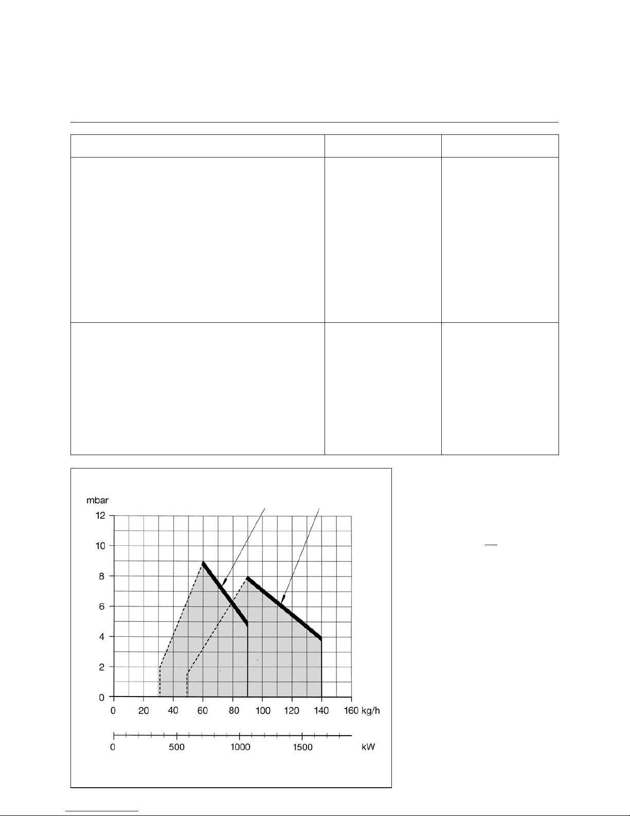
Performance charts
The performance charts reflect
the values approved during official
homologation.
Determining the required thermal output
Q
Q
K
F
N
=
h
Q
F
= Thermal output (kW)
Q
N
= Rated boiler capacity (kW)
h
K
= Boiler efficiency (%)
Thermal output Q
F
Oil throughput
Furnace pressure
EK4.100 L-ZA EK4.100 L-ZA
Page 4
09/2005 - Art. Nr. 13 019 533A
4
Survey
Dimensions
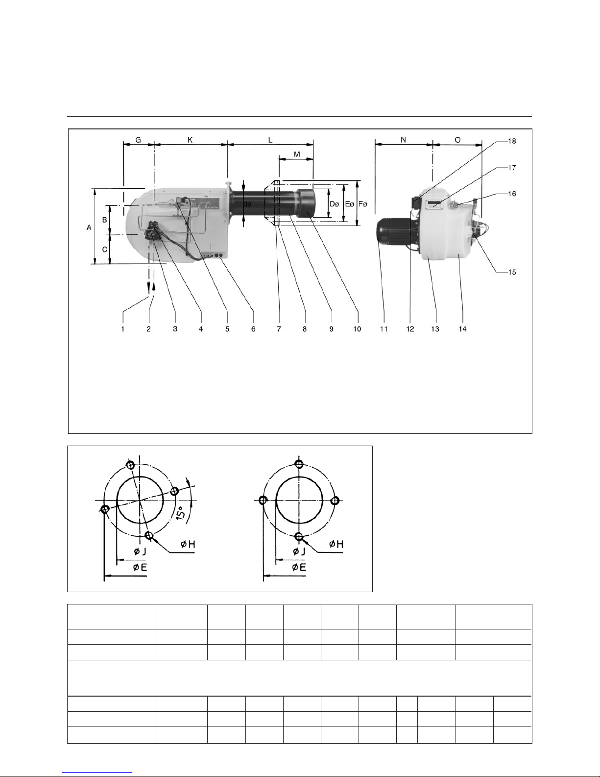
Key
EK = Manufacturer
4 = Size
160 = Performance rating
L = Fuel oil Extra Light
Z = Two-stage
A = Automatic burner control unit
1 Return line connection
2 Suction line connection
3 Solenoid valve, nozzle 2
4 Solenoid valve, nozzle 1
5 Solenoid valve for hydraulic air
damper drive
6 Switch box with automatic burner
control unit, switch, protective
motor switch and connecting
terminals
7 Connecting flange
8 Insulating base
9 Burner tube
10 Flame cup
11 Electric motor
12 Flame monitor
13 Burner housing
14 Air suction box
15 Oil pressure pump
16 Hydraulic air damper drive
17 Inspection glass
18 Ignition transformer
Burner type Thermal
output kW
A B C dø Dø Eø* Type No.
EK 4.100 L-ZA 360–1070 455 176 179 159 190 240–300* BN19787/89
EK 4.160 L-ZA 580–1660 455 176 179 185 220 280 BN19787/89
Customized designs and voltages on request.
* Long holes in burner connecting flange, graduated circle from … to …
Burner type F ø Fig. G H J K L M N O
EK 4.100 L-ZA 330 1 222 M12 200 430 520 120–406 382 307
EK 4.160 L-ZA 310 2 222 M12 230 430 535 125–380 382 332
Holes in the boiler connecting plate
Fig. 1 Fig. 2
Page 5

09/2005 - Art. Nr. 13 019 533A
5
Burner Functions
Functional Description
Functional Diagram
Starting function
The automatic burner control unit auto
matically starts the burner when heat is
required by the system.
–
The motor starts, the ignition is
switched on.
–
The air damper drive 6a switches the
air damper 5 to the low-load position (
in ”Basis” design, the air damper is in
the low-load position when the burner
is idle)
–
Preventilation
–
The solenoid valve 2 opens nozzle 1
–
The flame is formed (low load is in
operation).
Switching over to full load
If required by the system, the automatic
burner control unit switches the burner
to full load.
–
The solenoid valve 3 opens nozzle 2
–
At the same time, the solenoid valve
7 switches from passage b–c to
a–b
–
The hydraulic air damper drive 6
switches the air damper 5 to full load
(full load is in operation).
–
The ignition is switched off again
upon activation of full load.
Functional diagram
A Supply oil connection
B Return oil connection
C Combustion air inlet
D
1
Nozzle 1
D
2
Nozzle 2
1 Oil pressure pump with pressure
regulator
2 Solenoid valve for nozzle 1
3 Solenoid valve for nozzle 2
4 Nozzle rod with two nozzles
5 Air damper
6 Hydraulic air damper drive
6a Hydraulic air damper driver for air
cut-off
7 Solenoid valve for air damper drive
8 Combustion air blower
9 Safety solenoid valve (with design
”DIN”)
Safety functions
A fault shutdown is effected if:
–
a flame signal occurs during
preventilation (extraneous light moni
-
toring)
–
no flame occurs within 5
secondsafter starting the burner
(initial oil release)
–
the flame is extinguished during
operation.
A fault shutdown is indicated by the
flashing lamp in the reset button.
The program timer stops and the
location of the malfunction is indicated
(see Service Instructions, Malfunctions).
After eliminating the malfunction, press
the reset button to start the burner
again.
A controlled shutdown is effected if:
–
the medium temperature or pressure
is reached
–
the power supply fails.
The burner starts again automatically
as soon as the operating conditions
have returned to normal.
Basis
CEN/ DIN
Page 6

09/2005 - Art. Nr. 13 019 533A
6
Burner functions
Functional sequence of burner control units LAL 1...
The burner control units LAL 1... are
designed for controlling and monitoring
burners with multi-stage or modulating
control systems. For a detailed functio
nal description of the burner control
units, including technical data and
planning information, refer to
Technical Documentation
LAL 1 L&G 7153 D
Functional diagram, 2-stage
A = Start command
A–B = Interval for flame formation
B = Burner in operating position
B–C = Burner operation
(heat generation)
C = Controlled shutdown
t1 Pre-venting time
t2 Safety time
t3 Preignition time, short
t30 Preignition time, long
t3n Post-ignition time
t4 Interval between voltage on
terminals 18 and 19
t6 Post-venting time
t7 Interval between Start command
and voltage on terminal 7
t11 Opening time of air damper
t12 Closing time of air damper
t13 Admissible after-burning time
t16 Interval until OPEN command
for air damper
G Blower motor
R Temperature or pressure controller
Z Ignition transformer
BV Fuel valve(s)
FS Flame signal
LR Load controller
LK Air damper
Page 7

09/2005 - Art. Nr. 13 019 533A
7
Installation
Mounting the burner to the heat generator
Zero point adjustment
Electrical connection
Mounting the burner to the heat
generator
To mount the burner connecting flange
to the heat generator, prepare the con
-
necting plate according to the dimen
sions given on page 4. The connecting
flange 4 with the insulating base 3 have
been factory-mounted to the front of the
burner tube.
·
Set the desired burner tube length in
the furnace by moving the flange on
the burner tube
·
Insert the burner into the opening of
the heat generator and secure it.
Inspection glass cooling
To keep the boiler inspection glass cool
and clean, a cooling line may be
connected to connection 12 R
1/4”.
The cooling line can be either a hose or
a copper pipe.
A hose union is enclosed with the
burner.
To connect a copper pipe, a suitable
clamping ring connection is required.
Zero point adjustment, flame cup
Before the burner is operated for the
first time, the zero point must be
checked and adjusted, if necessary, so
that the zero mark on the scale corre
sponds to the zero position in the
burner head. Adjustment is made by
displacing the flame cup after releasing
the screw 1.
Electrical connection
Electric wiring must be carried out by
an authorized electrician according to
the enclosed wiring diagram.
The connecting terminals are located in
the built-in switch box.
For cable connection, ensure the
following:
·
Connect to terminal strip 8.
·
Provide sufficient length of cable so
that the burner and the boiler door
can be opened.
·
Do not install the sensor lead in the
multi-conductor cable.
The electric module can be removed for
connection, replacement or adjustment
of components.
5 Lock nut for electric module
6 Pushbutton, stage 1 - stage 2
7 Pushbutton On/Off
8 El. connecting terminals
9 Overload relay
10 Protective motor switch
11 Automatic burner control unit with
reset button
12 Connection for inspection glass
cooling
Disassembling the electric module
·
Set the main switch to off, remove
the fuse
·
Release the lock nuts 5
·
Carefully remove the electric module.
Caution!
Never apply voltage to the electric
module after disassembly.
After making the connections, check all
system components for correct wiring.
Then start the motor for a short time to
check its sense of rotation.
Page 8

09/2005 - Art. Nr. 13 019 533A
8
Installation
Oil connection
Oil pressure regulation
Start-up
Oil connection
Hoses are used for connecting the
oil pipes and the valve system. The
hoses must be properly installed
(suspended if possible) to avoid kinking
and the risk of fracture. For the dimen
sions of the supply and return pipes
from the valve system to the tank,
please consult the relevant technical
data sheets.
Mounting options
–
Direct single-pipe installation
–
Single pipe installation with vent
filter
–
Two-pipe installation
Filters
To protect the burner pump and the
hydraulic system, suitable filters must
be installed upstream of the burner.
Conversion from two-pipe to singlepipe installation
The burners are delivered with the
pumps fitted for two-pipe installation.
Conversion
·
Remove the bypass plug from the
return line connection and close the
return line R with the screw supplied
with the burner.
Attaching the measuring
instruments
·
Suction line vacuum gauge to con
-
nection 3
·
Oil pressure gauge to connection 4
Oil pressure regulation
The oil pressure is regulated by the
pressure regulator incorporated in the
pump. The correct setting is approx.
15–20 bar, depending on the burner
capacity.
The pressure regulator is actuated by
turning the screw 6.
Vacuum test (suction line)
The maximum permissible vacuum is
0.4 bar. A higher vacuum will cause the
heating oil to vaporize and may cause
malfunctions.
Pump type for EK4.160 L-ZA
R Return line connection
S Suction line connection
1 Solenoid valve, nozzle 2 (full load)
2 Connection, nozzle 2
3 Vacuum gauge connection
(suction line)
4 Pressure gauge connection
(oil pressure)
5 Screws for pump cover
6 Oil pressure regulator
7 Connection, nozzle 1
8 Connection, hydraulic air damper
drive
9 Solenoid valve, nozzle 1 (low load)
10 Pressure output
Start-up and ventilation
Switch on the burner for a short while
and check whether the sense of
rotation is correct. Loosen the oil pipe
union at the pressure output (7 or 10),
switch on the burner and run the burner
until bubble-free oil emerges. Then
reconnect the oil pipe.
Important!
The hydraulic system has been filled
with test oil at the factory. This may
cause ignition problems when starting
the burner for the first time.
Adjustment sequence
·
Start the burner
·
Adjust the oil pressure (15–20 bar)
·
Provisionally adjust low load
·
Switch over to full load
·
Finally adjust full load
·
Switch back to low load
·
Finally adjust low load
Pump type for EK4.100 L-ZA
Page 9

09/2005 - Art. Nr. 13 019 533A
9
Start-up
Burner head setting dimensions
The setting dimensions are standard
values which refer to 80% of the
maximum burner capacity. They can be
readjusted depending on operating con
-
ditions, flue gas analysis and combu
-
stion behaviour.
Important!
Check the settings by means of the
table before starting the burner for the
first time. Remove the nozzle connec
-
tion for this purpose.
Ignition electrodes
The ignition electrodes are directed to
nozzle 1.
Spare ignition electrodes must be bent
for replacement (at an angle of approx.
30° to the nozzle).
Burner head
1 Oil connection, minimum low load
1a Oil connection, maximum full load
2 Ignition electrode
3 Flame cup
4 Nozzle rod
5 Baffle plate holder
6 Nozzle
7 Baffle plate
Burner type Standard settings
ACDEHKL
Baffle plate/
nozzle rod
Electrode/axis
Electrode/
nozzle rod
Electrode gap
Baffle plate/
flame cup
max. longitudi-
nal adjustment
Oil filler neck/
scale plate 0
EK 4.100 L-ZA
27 7 20 3 20 50
EK 4.160 L-ZA
27 7 20 3 20 50
View Z
Page 10

09/2005 - Art. Nr. 13 019 533A
10
Start-up
Air regulation
Design ”Basis”
Low load
·
Release the lock nut 1
·
Use the screw 2 to adjust the
low-load air
·
Tighten the lock nut after
adjustment.
Full load
·
Release the lock nut 3
·
Use the screw 4 to adjust the
full-load air
·
Tighten the lock nut after
adjustment.
Air regulation, suction side
The combustion air is adjusted on the
hydraulic air damper drive.
Design ”CEN”/”DIN”
The closed air damper position is
adjusted by means of the screw 6
(standard factory setting).
Low load
· Release the plug screw 5. The screw
behind it is now accessible for
adjusting the low-load air.
· Retighten the plug screw.
Full load
·
Release the lock nut 3
·
Use the screw 4 to adjust the
full-load air
· Tighten the lock nut after
adjustment.
Important!
Make sure that you do not turn the stops
of the hydraulic drive forcefully towards
each other, i.e. adjust the stop screws
only as long as the air dampers move
synchronously. Violent and excessive
turning will destroy the pinion.
1 Lock nut
2 Air regulator, low load (Basis)
3 Lock nut
4 Air regulator, full load
5 Air regulator, low load (CEN)
6 Air regulator, air damper closed
(CEN)
7 Locking screws for longitudinal
nozzle rod adjustment
8 Fixing screw, nozzle rod
Air regulation, pressure side
Moving the nozzle rod changes the
available sectional area F in the flame
cup.
Adjusting the nozzle rod
·
Release the screws 7
·
Adjust the nozzle rod
·
Tighten the screws after adjustment.
The ideal position of the nozzle rod
is determined by analyzing the combustion
quality at low and full load.
To disassemble the nozzle rod, release
the screw 8.
Page 11

09/2005 - Art. Nr. 13 019 533A
11
Service instructions
Maintenance
Troubleshooting
Maintenance
Burner installations should be serviced
once a year. The combustion and
emission values should be checked and
readjusted, if necessary. All mechanical
and hydraulic functions should also be
checked and wearing parts should be
replaced, if necessary.
Any maintenance and repair jobs
may be carried out by authorized
experts only.
Check for operating ability
If a malfunction occurs, check first
whether all requirements for troublefree
operation have been met.
1. Check fuel level
2. Check power supply
3. Check if all control and safety
features, such as thermostat, safety
limiter, low-water cutout, electric
limit switches etc. are operative and
properly adjusted
Burner malfunction, electric
Burner malfunctions are indicated by a
malfunction lamp. The automatic burner
control unit LAL 1 is equipped with a
malfunction indicator that is very useful
for locating the cause of a malfunction.
Malfunction control program and
malfunction indicator
Automatic burner control unit LAL 1; for
detailed information, see L and G 7153.
Basically, the program timer and the
malfunction indicator stop whenever a
malfunction occurs. The symbol
displayed above the reading mark
indicates the type of malfunction:
w
No Start, e.g. because the
CLOSED signal from limit
reversing switch ”Z” (or from
auxiliary switch ”M”) is missing on
terminal 8, or because a contact
is open between terminals 4 and
5.
x
Start aborted because the OPEN
signal from limit reversing switch
”A” is missing on terminal 8.
Terminals 6, 7 and 15 remain
energized until the fault is
eliminated!
Burner malfunction, general
In the event of any burner malfunction
whose cause is not immediately identifi
able, check the program sequence by
means of the applicable wiring diagram
and the hydraulic system description
until you locate the fault.
z
Fault shutdown because the
flame supervising circuit is
defective.
v
Start aborted because the
position signal from auxiliary
switch ”M” for the small flame
position is missing on terminal 8.
Terminals 6, 7 and 15 remain
energized until the fault is
eliminated!
1 Fault shutdown because no flame
signal is present upon expiry of
the safety time.
F
Fault shutdown because the
flame signal has failed during
burner operation.
w
Fault shutdown on or after
completion of the control
program because of extraneous
light (e.g. flame not extinguished,
leaky fuel valves or shutoff
elements in the nozzle rod,
defective flame supervising
circuit, etc.).
a–b Starting program
b–b’ ”Blank spaces”
(no contacts actuated)
b(b’)–a Post-venting program
The automatic control unit can be reset
immediately after a fault shutdown.
After resetting (as well as after a power
failure or after eliminating a malfunction
which caused a fault shutdown), the
program timer will always returns to its
starting position, supplying voltage to
terminals 7, 9, 10 and 11 only, as deter
mined by the control program. Only
then will the control unit initiate another
starting sequence of the burner.
Note:
Operate the reset button for 20
seconds at the most.
Page 12

09/2005 - Art. Nr. 13 019 533A
12
Fabriqué en EU. Made in EU. Hergestellt in der EU.
Document non contractuel. Non contractual document. Angaben ohne Gewähr.
Adresse Service-Hotline
ELCO Austria GmbH
Aredstr.16-18
2544 Leobersdorf
0810-400010
ELCO Belgium n.v./s.a.
Pontbeeklaan-53
1731 Zellik
02-4631902
ELCOTHERM AG
Sarganserstrasse 100
7324 Vilters
0848 808 808
ELCO GmbH
Dreieichstr.10
64546 Mörfelden-Walldorf
0180-3526180
ELCO France
18 rue des Buchillons
74106 Annemasse
0450877624
ELCO-Rendamax B.V.
Amsterdamsestraatweg 27
1410 AB Naarden
035-6957350
NL
FR
DE
BE
AT
CH
 Loading...