

Page 1
User Manual
For Authorized Service Technicians
AEROTOP T Air-Water Heat Pump
with LOGON B WP61
12/2012 Art. 420010520000
Page 2

Table of Contents
2
Table of Contents ………………………………………………………………… 2
Product Overview …………………………………………………………………. 3
Basic Information ………………………………………………………………….. 4
Product Description AEROTOP T.................................................................... 5
Setup and Connection Safety, Transport and Installation..................................... 7
Hydraulic Connections, Condensate Drain....................... 8
Electrical Connection General………………………………………………………. 9
Unit Design, Terminal Assignment……………………….. 10
Switch box…………………………………………………… 13
Checklist Correct Installation of an Air-Water Heat Pump................ 16
Initial Startup Requirements, Parameterization, Upkeep........................ 17
Fan Speed Setting
AEROTOP TC: Setting of the Integrated Thermal Valve… 18
Indoor Installation Corner Setup…….............................................................. 19
Corner Setup with Noise Dampers..................................... 20
Corner Installation…….……………………………………. 21
Cutout Insulation Installation............................................. 22
Parallel Setup with Rigid Duct........................................... 24
Parallel Setup with Rigid Duct (with Noise Damper)….. 25
General Duct Installation Information................................ 26
Flexible Air Intake.............................................................. 27
Flexible Air Outlet............................................................. 28
Controller Unit Installation................................................. 29
Outdoor Installation Special Conditions, Installation Location.......................... 30
Base/Pedestal Plan........................................................... 31
Duct and Cable Bushing………........................................... 32
Controller Unit…………………………………………......... 33
Troubleshooting AEROTOP T LOGON B WP61 Troubleshooting.............. 34
Initial Startup AEROTOP T Checklist...................................................... 37
System Sensor Characteristics NTC1, NTC10.............................. 39
Technical Data AEROTOP T07(C)-T16..................................................... 40
AEROTOP T20-T35.......................................................... 41
AEROTOP T07(C)X-T10(C)X........................................... 42
AEROTOP T07R-T16R..................................................... 43
AEROTOP T20R-T35R..................................................... 44
AEROTOP T07RX-T10RX................................................ 45
Conformity Declaration .......................................................................................... 46
Notes .......................................................................................... 51
Page 3

Product Overview
AEROTOP T
The air-water heat pump
AEROTOP T is available
in the following models:
AEROTOP T..C
The designation AEROTOP T..C includes
the following models:
• AEROTOP T..C
• AEROTOP T..CX
AEROTOP T..
The designation AEROTOP T.. includes
the following models: :
• AEROTOP T07-T35
• AEROTOP T..X
• AEROTOP T..R
• AEROTOP T..RX
3
Compact models ..C..
Up to models AEROTOP T12C and AEROTOP T10CX
the heat pumps are compact design with integrated
buffer tank, electrical resistance, expansion vessel
and circulation pump.
Single-phase models ..X..
Up to modesl AEROTOP T10X and T10CX single-phase
versions are also available.
All other models are three-phase
Reversible models ..R..
The reversible heat pumps can be used, as well as for heating,
even for the active cooling
Model for outdoor installation
With the right accessories the AEROTOP T are also suitable for
outdoor installation (not T.. C..).
Page 4
Basic information
Legal guidelines
Warranty conditions
Receiving inspection
General information
• The calculations, sizing, installa-
installations and putting into service related to the products described in this document may only be
carried out by qualified specialists
• Comply with the requirements of
local law, which may differ from the
information contained herein
• Subject to change.
These instructions are for aproper installation, adjustment and maintenance of the
machine. It is therefore necessary to read
carefully the instructions given below and
to install, test and maintain the heat pump
by technicians qualified by specific training.
At the end of the warranty period, the manufacturer assumes no responsibility for
mechanical, hydraulic or electrical changes.
In the case of operations not expressly
authorized, executed in violation of these
instructions, the warranty will become void
with immediate effect.
During the installation must meet the specific safety statements. Check that your
mains supply correspond to the data of the
heat pump (nameplate).
These instructions and the wiring diagram
of the heat pump should be stored with due
care and, if necessary, be made available
to the personnel responsible .
The manufacturer declines any responsibility for damage to persons or property caused directly or indirectly from failure to follow these instructions.
The housing may only be opened by a qualified technicians.
Limitations and Guidelines
The construction and the manufacture of
heat pump meets all the requirements of
European standards. (See EC Declaration
of Conformity).
The electrical connection of the heat pump
must be performed in compliance with the
applicable ASE, EN and IEC. Should also
observe the connection conditions of the
local energy supply
Warranty Conditions
Our performance guarantee shall lapse
for damage due to:
• misuse or non standard use
• installation or commissioning
incorrect by the purchaser or
from other.
• Use of the system with pressure
excessive or outside the factory
values
• Failure to follow directions in the
instructions for use
The warranty for heat pumps for
heating is 24 months from the date
of delivery.For the rest, the conditions of sale, delivery and warranty
in accordance with the order confirmation.
Control Input
The units are delivered on a wooden
pallet with an adequate protective
packaging.
Upon delivery, check the unit for
shipping damage and that the budget is complete.
If damage is found, they must be
reported immediately to the transport
document with a warning:
"Acceptance qualified as a result of
blatant corruption."
Given that overloading can cause
serious damage to heat pump and
plant heat source side, it is forbidden
to operate the heat pump if the following conditions exist:
• drying of the construction.
• plant is not completed
(building shell).
• windows and exterior doors
are not finished and closed.
In these cases it is necessary to provide a heating pipeline. A functional
heating or heat pump ready pose in
according to the DIN EN 1264 should
be only taking into account the above
conditions. Furthermore, keep in
mind that after the sizing of the heat
pump for normal operation may not
be possible to generate all the necessary thermal power.
Observe the following guidelines:
• Comply with the regulations
and requirements of the manufacturer of mortars for screed coat!
• Correct operation is only pos-
sible with a system installed in
a workmanlike manner (the
hydraulic, electrical, settings)!
Otherwise, the screed coat
may be damaged!
Low energy consumption use of
the heating with heat pump
The decision to opt for a heating
system with heat pump is a valuable
contribution to protecting the environment by reducing emissions and
reduced use of primary energy. In
order for the new heating system will
work efficiently, note the following
points:
L
The heating system with heat pump
must be sized and installed with care.
L
The lower is the flow temperature of
the heating water side, the more
efficient is the operation of the heat
pump.
L
Give preference to a short-term intensive aeration of the premises.
Compared to the windows always
open in the tilted position, this immediate ventilation reduces the consumption of energy.
4
Page 5

Product Description
AEROTOP T
5
High Degree of Efficiency and
Optimized Defrosting
Thanks to the correspondingly dimensioned air heat exchanger as well
as the unique defrosting system, the
AEROTOP T heat pump is especially
efficient and a cost-saver. This heat
pump always exceeds the required
degree of efficiency (coefficient) of
3.0 (COP at A2W35).
Frost forms on the air exchanger, the
evaporator, if the exterior temperature
is less than 5°C. This results in ice
formation and as a consequence
reduced the heat exchange and with
that the efficiency of the heat pump.
The evaporator must be defrosted to
remove this frost or ice. However, the
defrosting process, carried out by the
AEROTOP T by reversing the cooling
circuit, is cumbersome since the heat
pump does not yield any energy during
the defrosting process but still uses
electricity. However, this is frequently
unnecessary since frost formation
depends on the humidity in the air.
Instead of the unnecessary defrosting
at timed intervals, the AEROTOP T
determines the correct time to defrost
the unit using a progressive and well
thought out logic with different performance parameters in the cooling
circuit. Thanks to this procedure, the
unit rarely requires any defrosting
during winter, if any at all, which is a
great advantage.
Cooling with AEROTOP TR
The purpose of heat pumps is primarily
to supply a building with heat. However,
the technology can also be used to
cool a building in the summer.
This involves actively generating the
cooling energy through a process
reversal of the heat pump. In case of
distributor systems specifically
designed for cooling (fan coil or similar), the cooling capacity of the heat
pump can be transferred optimally to
the building. Cooling ceilings also
have a good cooling capacity and
comfort level. Floor heaters, however,
are only partially suited and provide a
limited cooling effect. Radiator heaters
are unsuitable.
Cascade
Thanks to the new heat pump controller
LOGON B WP61, it is possible to link
and operate several heat generators of
a system in a cascade arrangement.
Cascades with up to 4 heat pumps, or
a bivalent operation in combination with
fossil heat generators are feasible.
When using a cascade formation, the
heat generators switch on or off
depending on the current energy
demand: If the currently running heat
pump cannot satisfy the energy
demand within a specific time, an
additional heat pump/heat generator
switches on.
Quiet Operation
Regardless whether installed indoors
or outdoors, the air-water heat pump
AEROTOP T is characterized by
comparatively very low noise
emissions. This is possible thanks to
the high-performance fan, the very
advantageous air routing, the
noise--dampening insulation of the
cladding, as well as the
multi-dampened support of the cooling
circuit. Additional noise insulation
elements are available for most
variants to reduce sound emissions
further. AEROTOP T heat pumps are
quiet and efficient. However, incorrectly
integrating constructional components
may result in undesired noise increases
if the conditions are unfavorable.
Flexible and Space-Saving
Some air-water heat pumps are
relatively bulky due to the required
cross-sections for the air ducts or
application options are severely limited.
Thanks to the clever utilization of the
geometric properties of the radial fan,
AEROTOP T are among the most
flexible, space saving air-water heat
pumps.
Especially noteworthy is the fact that
the heat pump can be placed into the
left or right corner of the utility room
when not using the air ducts.
The exhaust opening is easily moved
on-site from the left to the right and
even to the top without having to use
any additional tools. The intake opening
can also be selected as desired without
special accessories. AEROTOP T heat
pumps are also suitable for outdoors
installation when using the corresponding accessories.
Page 6

Product Description
AEROTOP T
6
Enclosure and Special Components
The enclosure consists of a frame that
is completely free of thermal bridging,
sound dampened, and specifically
developed for use with heat pumps.
The cladding and panels feature a
high-grade insulation to sound-dampen
and thermally insulate the unit.
A pedestal or base is not required
since the feet of the unit feature a
vibration-dampening design.
All panels can be detached for easy
access to the internal elements of the
unit and for control or configuration
tasks.
The high-performance radial fan
ensures the unit runs efficiently and
quietly.
The high performance cooling circuit
is mounted on a vibration-dampened
support and features a thermostatic
expansion valve, filter dryer, inspection
glass, high-pressure pressure controller
with manual reset, and a low-pressure
pressure controller with automatic
reset function. The hermetic scroll
compressor is mounted on a double
vibration-dampened support.
The evaporator consists of a large-area
finned tube heat exchanger made from
aluminum and copper; the condenser
consists of a welded chromium steel
high performance plate heat exchanger. The environmentally friendly
refrigerant R407C is used as the
working medium. A flow monitor on
the consumer side ensures trouble-free
cooling for reversible heat pumps.
Operating the heat pump is prohibited if
the following conditions exist:
• Construction drying
• System/unit used in unfinished
buildings
• Windows or exterior doors
unfinished and locked.
These cases require the use of a
specific construction heating system.
Functional heating or surface-ready
heating with the heat pump acc. to
DIN EN 1264 is only permitted when
complying with these conditions.
Furthermore, it must be noted that the
design of the heat pump concerning
its standard operation may not yield the
full extent of the required heat output.
The following notes must be observed
as well:
• Comply with the corresponding
standards and rules of the floor/
screed manufacturer!
• Proper function is only ensured
with a correctly installed system
(hydraulics, electrical, settings)!
Deviations may damage the floor/
screed!
Brief Description of the LOGON B
WP61 Controller
Plain text display unit, control and
protection of the cooling circuit, defrost
logic, malfunction display and diagnostics, control of a sliding or mixed
heating circuit, service water heating,
storage tank charging, control of the
electrical auxiliary heater, expandable
for several mixed heating circuits.
LPB system bus with up to 15 heating
circuits per segment, bivalent operation
with additional heat generator (oil/gas),
cascade of several HPs. cooling
function, improved solar function
(heating support, pool, PWH), pool
function, controlling the multi-phase
electrical heating elements.
Selectable Connections
The connections for heater flow and
return, condensate drain, and electrical
connections can be placed on the left
or right side during the on-site installation and even directed towards the
bottom when installed outdoors.
Page 7

Setup and Connection Instructions
Safety, Transport and Installation
7
Transport
To avoid transport damages, the heat
pump must remain packaged and on
the wooden pallet and transported to
its final installation location with a hand
lift, pushcart, or similar equipment.
• Make sure the heat pump does
not slip on the equipment used for
transport.
• Components and piping of the
cooling circuit, the heater side, and
the heat source side may never be
used for transport purposes.
• Note the weight of the heat pump.
• Make sure the water hoses and
electrical lines are not damaged
during transport.
• Only lift and transport the heat
pump at and with the unit's bottom
panel.
Safety Information
• Compliance with all rules and
instructions of all documentation,
labels, type plates, and associated
documents of the unit is
mandatory.
Transport
• When receiving the shipment, the
heat pump must be checked for
completeness as per order
confirmation .In case of damaged
or missing material, the carrier
must be informed in writing
immediately.
• Care and due diligence are
required during transport, setup,
preparation, or when handling
heavy materials that may damage
the heat pump.
• Make sure that towing ropes, belts,
or chains used for transport or
installation do not damage the heat
pump. Do not allow the heat pump
to swing back and forth when lifting
it up. Never tilt the heat pump more
than 15° from its vertical axis.
• The heat pump is affixed to a pallet
at the factory for transport and
covered with a protective film to
protect the unit from scratches. Do
not remove the packaging until the
heat pump is positioned at its final
location.
Setup
• Setup must be carried out carefully
and accurately.
• AEROTOP T heat pumps can be
installed on a level interior floor
without pedestal or base.
If installed outdoors, a pedestal or
base is required unless the
substrate is very firm and can
support the load.
• The installation room must have at
least one exterior wall. Rooms with
high humidity are unsuitable as
installation locations for
AEROTOP T heat pumps. A
condensate drain must be
available.
• The heat pump must be set up on
a level ground and aligned with the
adjustable feet. Make sure there is
sufficient space to access the
control panel and at the sides for
inspections and maintenance.
• Make sure the ground is able to
support the load of the heat pump
and all accessories. The floor or
ground must be free of dust and
other foreign particles. If installing
in the basement, make sure the
selected installation position
cannot be flooded.
• The heat pumps may not be placed
on floating floorings.
• Once moved to its final location,
the heat pump must be carefully
unpacked and removed from the
pallet. Protect heat pump from
impact and other damaging forces!
Installation
• The safety regulations and
schemes/diagrams must be strictly
observed.
• The accessories and additional
equipment must be installed by a
trained service technician (heating
contractor) as per the enclosed
assembly and installation
instructions.
• The noise emissions of the
AEROTOP T heat pump are very
low thanks to the sound-absorbing
materials used to mount the mobile
parts and the insulating cladding.
The effective noise value depends
also on the size of the installation
room, the noise-absorbance or
reflection of the materials in the
room, as well as the possibility of
the noise to spread and transfer
via solid bodies, among others.
• Air ducts, pipes, and electrical lines
must be attached to the masonry
and not the heat pump.
• All of these connections must be
established using flexible
connections so that they can swing
freely, especially when the
compressor or evaporator starts
up. Only then is it possible to avoid
transference of sound from solid
bodies to the building structure as
well as line breakages.
Observe the checklist notes when
selecting the installation site for the
correct setup of an air-water heat
pump
Page 8
Setup and Connection Instructions
Hydraulic Connections, Condensate Drain
8
Heating System Hydraulic
Connections
AEROTOP T heat pumps can be
connected in any desired layout.
The hydraulic connections require
flexible ducts to avoid noise transference from pipe openings and solid
bodies to the distributor network and
from there to the heating elements
such as radiators, etc. The ducts can
be directed from the right or left and
are connected to the inside of the heat
pump.
The ductwork must be carried out in
such a way that pressure drops at the
nominal volume flow do not exceed
the available pressure since this would
result in a reduction of the heat pump
output. This means that ducts cannot
have elbows that are too narrow.
Pipes and ducts must also be sufficient
insulated to prevent unnecessary heat
loss and the formation of condensate,
which could damage the pipe and duct
system or the installation location.
Dimensions
Heater flow Ø 1” (T07-T16),
Ø 1 1/4” (T20-T35),
flexible. Heater return Ø 1” (T07-T16),
Ø 1 1/4” (T20-T35), flexible,
Condensate Drain Ø 25/31mm, flexible.
For each heat pump we offer hydraulic
standard schemes. The integration of
these variants guarantee a safe and
faultless operation.
The system must be thoroughly
flushed before connecting to the heat
pump.
Residues in the heat pipes lead to
damages on the heat exchangers und
to malfunction of the heat pump.
Especially if there is no buffer storage
it is recommended to a dirt trap in the
heating return flow.
The water filled into the heating system
must be handled in accordance with the
rules and regulations of the relevant
professional associations.
It is important to ventilate the heating
system. If not the correct operation of
the heat pump is affected. Therefore
an exhauster must be provided. The
compact heat pumps have an
exhauster installed in the flow.
Condensate Drain
The condensate drain should be as
close to the heat pump connection as
possible. To prevent room air or
canalization waste air from being
sucked into the heat pump, the
condensate drain must be connected
airtight to the heat pump using a
siphon with a min. height of 100 mm.
The condensate drainage pipe cross-section may not be reduced and must
be at a continuous 2% incline to ensure
water can be sufficiently drained.
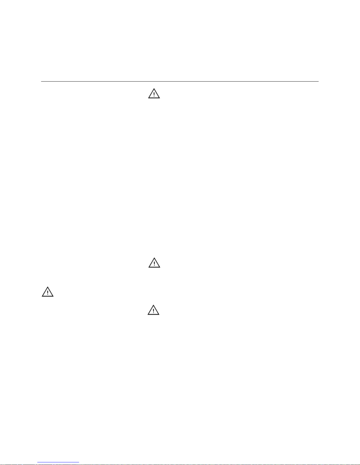
Changing the Hydr. and Electr.
Connections
Lines are connected at the left side of
the unit by default. If the right side is
preferred, the panels (1 and 2) can be
switched with the panels from the left
side. Ducts and cables are pulled to
the other side inside of the unit and
through the opening in panel 1.
1 2
Page 9
Electrical Connections
General
9
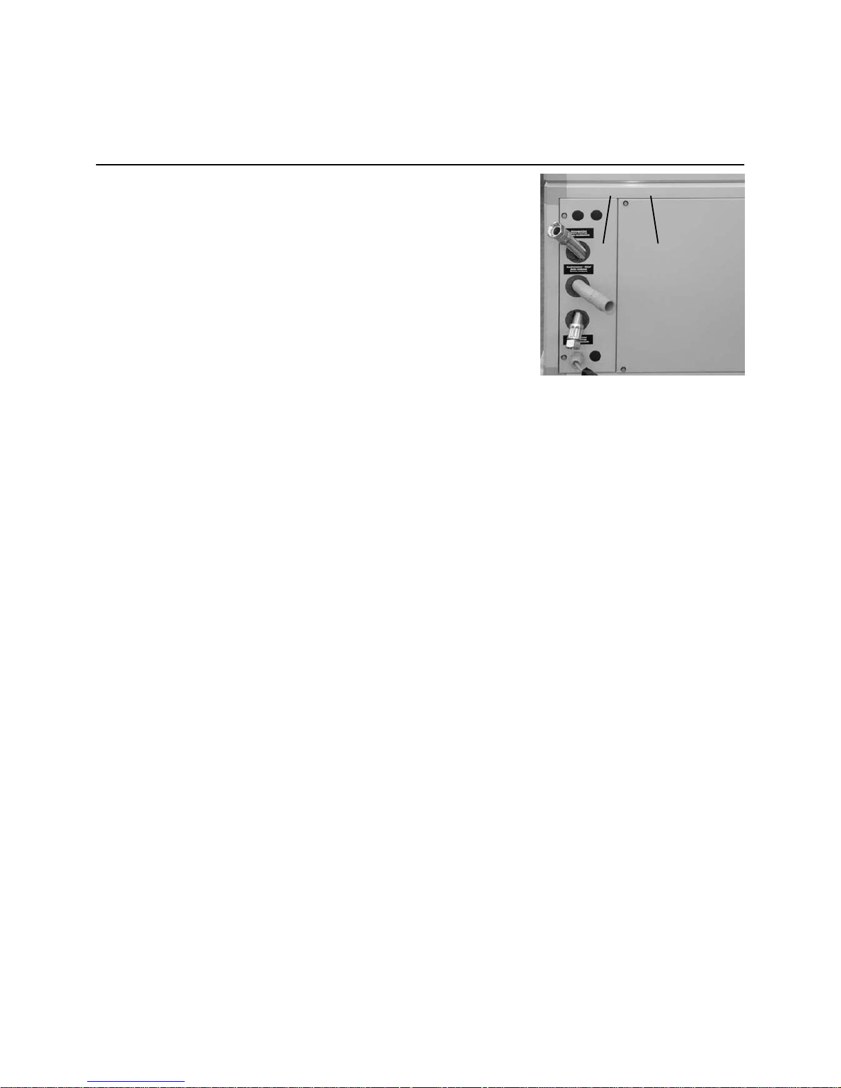
Cable Entry Point
1 Entry point for load cable 3 x 400V
2 Entry point for low voltage/sensor
cable
3 Fastening screws
Detach screws (3) and push cover
plate towards front. This makes it easier
to pull through the low voltage cables (2).
After inserting the cables, push cover
back into place and refasten the
screws (3).
1
2
3
Electrical Connections and Control
Information
The electrical connections must be
established in compliance with local
rules and regulations. The current feed
may exhibit a max. tolerance of 2%
with this power intensity when a voltage
of 10% exists. Do not connect the heat
pump if the phase difference exceeds
more than 2%. (EN 60439-1)
Operating the equipment
outside of the listed limit values will void
the warranty. If necessary, please
contact your local electricity company
or utility. The internal wiring of the heat
pump is carried out at the factory as
listed on the electrical diagram included
with the unit.
The heat pump is equipped with an
electrical supply box containing the
components listed below.
• An automatic cutout switch or a
3 phase, slow-blow fuse with
neutral conductor must be provided
externally in compliance with the
technical requirements.
• The low voltage cables (control)
may not be placed in the same
cable conduits or ducts as the
supply cables.
• The exterior temperature sensor of
the controller must be attached to
the outside wall of the building in a
location protected from the after noon sun and other heat sources
(open windows, chimneys, etc.).
Northern and northeastern
exposures are preferred.
• If the room impact is to be
activated for a remote control, this
control unit must be placed in a
reference room (e.g. living room)
where it cannot be influenced by
an external heat source (e.g.
stoves, heaters, air flow, etc.).
Main Power
Heat Pump Models
(Also applies to same models in reversible (R) designs.
Ext.-Fuse Cross-section
terminal board
[A] [mm
2
]
AEROTOP T07CX (X)+ Electrical Heating Element R25 (6kW) 1x50 16
AEROTOP T10CX (X)+ Electrical Heating Element R25 (6kW) 1x63 16
AEROTOP T07C/T10C/T12C+Electrical Heating Element R25 (6kW) 20 4
AEROTOP T07/T10/T12+Electrical Heating Element R25 (6kW) 20 6
AEROTOP T14/T16 +Electrical Heating Element R25 (6kW) 25 6
AEROTOP T20 25 10
AEROTOP T26 32 10
AEROTOP T32-35 40 10
Page 10
Air in
Air out
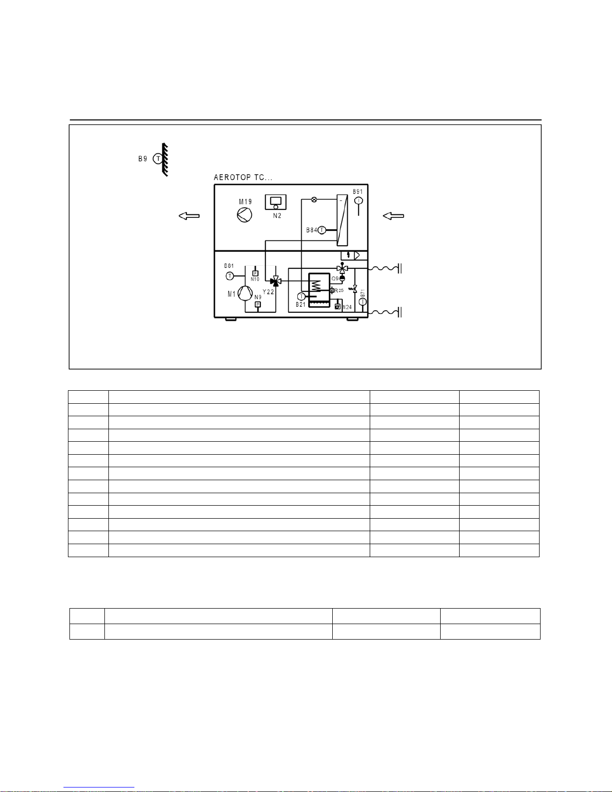
AEROTOP T..C..
Electrical Connections
Unit Design, Terminal Assignment
Description RVS61 Slot RVS61 Output
N9
Low pressure K E9
N10
High pressure K E10
Y22
Process reversal valve Y22 W QX1
R25
Electrical heater element 1 flow W QX2
B81
Hot gas temperature sensor 1 f B81
B21
Heat pump flow temp. sensor n B21
B71
Heat pump return temp. sensor q B71
B91
Source intake temp. sensor r B91
B84
Evaporator temp. sensor s B84/B92
M19
Fan z UX
N24
Flow monitor consumer P EX3
Q9
Condenser pump V Q9
Controller terminal assignment of components wired at the factory:
Description RVS61 Slot RVS61 Output
B9
Outdoor temperature sensor k B9
Other important components to be wired in the system
Please consult the electrical diagram of the heat pump for complete terminal assignments and electrical connections.
10
Page 11
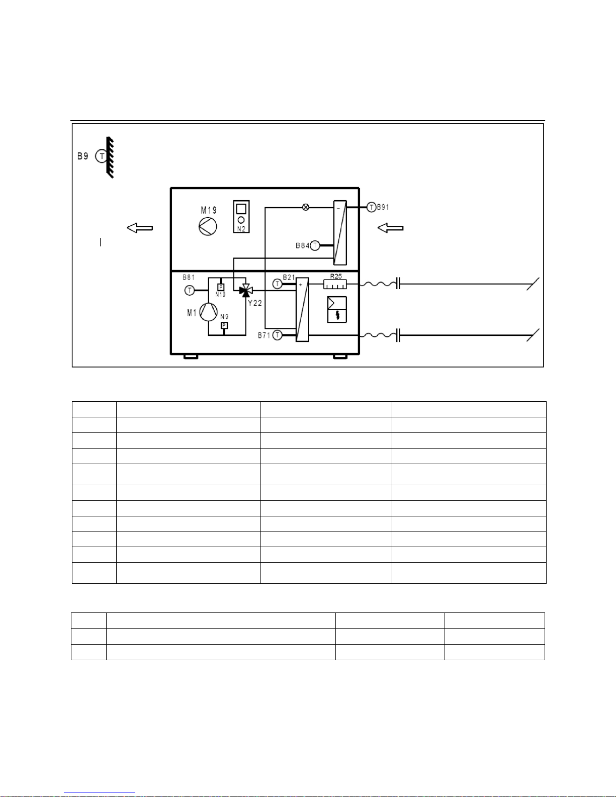
Air in
Flow sensor
Return sensor
Air out
Electrical Connections
Unit Design, Terminal Assignment
AEROTOP T..
Description RVS61 Slot RVS61 Output
N9
Low pressure K E9
N10
High pressure K E10
Y22
Process reversal valve Y22 W QX1
R25
Electrical heater element 1 flow
(only with AEROTOP T07 to T16)
W QX2
B81
Hot gas temperature sensor 1 f B81
B21
Heat pump flow temp. sensor n B21
B71
Heat pump return temp. sensor q B71
B91
Source intake temp. sensor r B91
B84
Evaporator temp. sensor s B84/B92
M19
Fan z (AEROTOP T07-T16)
U (AEROTOP T20-T35)
UX (AEROTOP T07-T16)
Q8-K19 (AEROTOP T20-T35)
Controller terminal assignment of components wired at the factory:
Please consult the electrical diagram of the heat pump for complete terminal assignments and electrical connections.
Description RVS61 Slot RVS61 Output
Q9
Condenser pump V Q9
B9
Outdoor temperature sensor k B9
Other important components to be wired in the system
11
Page 12

Electrical Connections
Unit Design, Terminal Assignment
Air in
Air out
Flow sensor
Return sensor
Description RVS61 Slot RVS61 Output
N9
Low pressure K E9
N10
High pressure K E10
N24
Flow monitor consumer P EX3
R25
Electrical heater element 1 flow (only with AEROTOP T07 to T16) W QX1
Y22
Process reversal valve Y22 W QX2
B81
Hot gas temperature sensor 1 f B81
B21
Heat pump flow temp. sensor n B21
B71
Heat pump return temp. sensor q B71
B91
Source intake temp. sensor r B91
B84
Evaporator temp. sensor s B84/B92
B83
Liquid refrigerant sensor B83 y BX5
M19
Fan z UX
Controller terminal assignment of components wired at the factory:
Description RVS61 Slot RVS61 Output
Q9
Condenser pump V Q9
B9
Outdoor temperature sensor k B9
Other important components to be wired in the system
Please consult the electrical diagram of the heat pump for complete terminal assignments and electrical connections.
12
Page 13
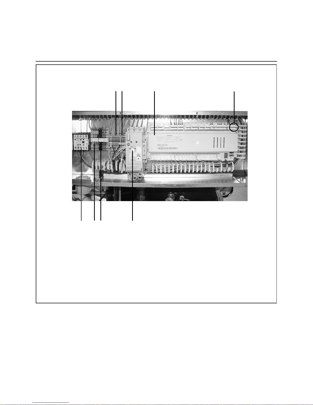
13
AEROTOP T..C
5 Contactor electric heating element
6 Main incoming supply 3*400V
7 Fan fuse / control fuse (F3)
8 Soft-starter and rotary current relay
Electrical Connection
Switch box
1 2 3 4
5 ....6 7 8
Legenda:
1 Terminal strip consumer, power
station blockage
2 Terminal strip Fan Contactor / oil
sump heater
3 Heat pump controller
LOGON B WP61
4 Mains supply plug:
Mains connector phase AC 230 V
Main connector neutral connector
Page 14

Electrical Connection
Switch box
10 7 6 3 4
11 5 9 1 2 8
AEROTOP T..CX
5 Contactor electric heating element
6 Main incoming supply 3*400V
7 Fan fuse / control fuse (F3)
8 Soft-starter and rotary current relay
9 Fan Contactor
10 Electr. heater element fuse
F6.1/F6.2/F6.3
11 Compressor fuse
Legenda:
1 Terminal strip consumer, power
station blockage
2 Terminal strip Fan Contactor / oil
sump heater
3 Heat pump controller
LOGON B WP61
4 Mains supply plug:
Mains connector phase AC 230 V
Main connector neutral connector
14
Page 15
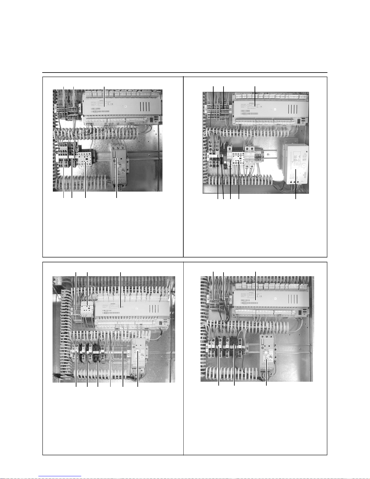
15
Electrical Connection
Switch box
Electrical Box AEROTOP T20-T35 with LOGON B WP61
1 Terminal block consumer (EC block / source flow monitor)
2 Terminal block foil sump heater
3 Terminal block Fan contactor
4 Heat pump controller RVS61
5 Main incoming supply 3*400V (L1, L2, L3)
6 Fan fuse (F19-1-2-3)
7 Control fuse (F3)
8 Soft-starter and rotary current relay
9 Fan contactor K19
Electrical Box AEROTOP T07-T16 with LOGON B WP61
1 Terminal block consumer (EC block / source flow
monitor)
2 Terminal block fuse fan / oil sump heater
3
Heat pump controller RVS61
4 Main incoming supply 3*400V
5 Fan fuse / control fuse
6 Soft-starter and rotary current relay
7 Contactor electric heating element
1 9 4
5 6 7 2 3 8
Electrical Box AEROTOP T20R-T35R with LOGON B WP61
1 Terminal block consumer (EC block / source flow
monitor)
2 Terminal block fuse fan / oil sump heater
3
Heat pump controller RVS61
4 Main incoming supply 3*400V
5 Fan fuse / control fuse
6 Soft-starter and rotary current relay
Electrical Box AEROTOP TX e TRX with LOGON B WP61
1 Terminal block consumer (EC block / source flow
monitor)
2 Terminal block fuse fan / oil sump heater
3 Heat pump controller RVS61
4 Main incoming supply 3*400V
5 Fan fuse / control fuse
6 Soft-starter and rotary current relay
7 Contactor electric heating element
8 Compressor Fuse
1 2 3
4 5 8 7 6
1 2 3
4 5 7 6
1 2 3
4 5 6
Page 16
Checklist
Correct Installation of an Air-Water Heat Pump
AEROTOP T heat pumps are quiet
and efficient. However, incorrectly
integrating constructional components
may result in undesired noise increases if the conditions are unfavorable.
A careful assessment of the noise
emissions is required when planning
the installation of heat pump systems.
Noise reduction measures considered
early on in the development process
result in the fewest additional costs.
Subsequent measures usually are
extremely expensive and cumbersome
to implement. [Heat Pump Manual,
Federal Energy Agency, Switzerland]
The following points apply to the
interior and exterior installation of
air-water heat pumps.
16
To be considered when installing an air-water heat pump
Each reflecting surface doubles
the noise (acoustic power).
One wall increases this value by
+3dB, one corner by +6dB.
one corner by +6dB.
Avoid solid-borne noise transmission by avoiding reflecting surfaces. Never route air
intake or outlet into closed or partially closed spaces such as a corner, foyer, entrance
area, covered patio, etc.
Rooms with reverberant or
sound-reflecting floor coverings
and walls increase the noise
level.
Avoid rooms with reverberant or sound-reflecting floor coverings and walls. When
installing the heat pump in a room with reverberant or sound-reflecting floor coverings
and walls, reflections may increase the sound level. Cover one or two walls with
noise-absorbing material if this is the case.
Adherence with the min.
clearances reduces noise
reflection and air short-circuits
and improves airflow near the fan.
Make sure the min. distances and clearances to the air intake and outlet as well as the
min. size of the light wells are applied. Avoid walls or flow barriers around the
circumference of the heat pump to ensure air can reach the fan evenly.
Less pressure losses = low peripheral speed = reduction of the fan noise.
Construction measures can
reduce noise, plants cannot.
Use constructional measures to interrupt the flow of noise from the heat pump
(direct noise propagation). Use solid walls, fences, palisades, etc. to reduce noise
levels. Plants, however, do not reduce noise.
Consider different noise
sensitivity levels.
Avoid placing the heat pump where it may cause problems due to its noise emission
(bedrooms, living rooms, neighbors, etc.). Position heat pumps in areas where noise is
less likely to be an annoyance. If installed indoors, do not install underneath or next to
living or sleeping quarters.
Sound absorbing materials
reduce noise.
Additional sound absorbing materials or measures must be planned for and used in
cases where extreme noise reductions are desired or when installing model Forever
GREEN 20C or later. Use only original accessories and spare parts. in extreme cases,
it may be advisable to consult a noise expert.
Separation from the structure
minimizes structure-borne
sounds.
Always use flexible connections throughout: Flexible hoses and tubes for heat
distribution, flexible electrical connections, sound isolation of the air ducts by using
elastic sleeves or Compriband products.
Correct installation of pedestal
or base reduces structure-borne
sounds.
The base or ground must be level or made level and able to support the load of the
equipment. Use the adjustable feet of the heat pump to level the equipment after
installation.
Correct installation of the ducts
reduces air and structure-borne
noise transference.
All wall openings and ducts must be equipped with the corresponding noise-absorbing
materials. Comply with the specified cross-sections and dimensions.
Avoid air short-circuits and airflow
barriers.
Air intakes and outlets cannot be installed next to each other without using a
separating wall. Avoid any airflow obstacles that favor an air short-circuit.
Always comply with all rules,
regulations, and applicable laws.
Germany: Technical Instructions on Noise
Switzerland: Noise Protection Ordinance
Be careful with dropping the
washing
Dropping the washing from lived-in rooms to the place of installation of the heat pump
can lead to noise transmission when unfavourably positioned.
Page 17

Initial Startup
Requirements, Parameterization, Upkeep
17
Requirements for Initial Startup
(Commissioning)
The initial startup of the AEROTOP T
heat pump must be carried out by our
qualified technicians or the warranty will
become void.
Operating the heat pump is prohibited if
the following conditions exist:
• Construction drying
• System/unit used in unfinished
buildings
• Windows or exterior doors
unfinished and locked.
These cases require the use of a
specific construction heating system.
Functional heating or surface-ready
heating with the heat pump acc. to
DIN EN 1264 is only permitted when
complying with these conditions.
Furthermore, it must be noted that the
design of the heat pump concerning its
standard operation may not yield the
full extent of the required heat output.
The following notes must be observed
as well: The corresponding rules and
regulations of the floor/screed manufacturer! Proper function is only ensured
with a correctly installed system
(hydraulics, electrical, settings)!
Deviations may damage the floor/screed!
Ensure the following points are implemented and checked before the initial
startup of the heat pump:
• The control box is installed and
completely connected.
• The heat pump is professionally
and completely installed (hydraulics
and electrical).
• All external system components
required for operating the heat
pump (circulation pumps, three-way
valves, sensors, etc.) are completely
and professionally connected.
• The hydraulic connections have
been established completely and
professionally.
• All sensors are professionally
installed, shielded, and positioned
in the correct locations as outlined
by the respective system scheme.
• The heating system is profes-
sionally installed and has been
flushed, charged, vented, and
checked for leaks as per rules and
regulations.
• The electrical voltage meets the
requirements listed on the type
plate of the heat pump.
• All fittings are in operational position.
The following persons must be
present to carry out the initial startup
process:
• The planer; he or she must indicate
the operational parameters.
• The installer; he or she is responsi-
ble for the functionality and settings
of the hydraulic system.
• The system maintainer (customer
or representative); he or she will
be instructed in the operation and
functions of the system.
If an initial startup is requested without
all of these conditions having been met,
ELCO rejects any responsibility for
system malfunctions or other operational problems. In this case, the
system is operated at the risk and responsibility of the owner.
Parameterization
The heat pump and the entire system is
controlled with the integrated LOGON B
WP61 controller. Please consult the
system documentation for the correct
parameter settings.
After the Initial Startup
After the initial startup is finished, the
AEROTOP T heat pump does not
require any additional interventions or
adjustments to the controller.
Any desired heating temperature
adjustments can be made in accordance with the enclosed user
manual for the LOGON B WP61
controller.
Controller Function
Different temperature sensors and
measuring elements in the heat pump,
at the exterior air, in the system, in the
storage tank, in the hot water tank, and
possibly also in the living quarters are
used by the controller.
If and as needed, the controller passes
a heat demand signal to the heat pump.
The input of a heating curve is used
to control and adjust heating temperatures. The heat pump as well as the
system is controlled automatically.
The system-relevant parameters are
entered when commissioning the
climate-based controller.
Heat Pump Upkeep
The AEROTOP T heat pump does not
require any special upkeep. However,
it is important to keep the system clean
and in good working order.
The specified leak checks must be
carried out as well. From an energetic
viewpoint, it is also recommended, especially in case of a new construction,
to have the heating parameters
checked and optimized by a service
technician during the second winter
after the initial startup since the initial
humidity has now evaporated from the
building and the required heating
output is less than initially.
Primary focus should be on keeping air
intake and outlet free of dust and other
foreign particles or objects. The air
intake and outlet openings must be
kept free of obstructions (e.g. leaves,
vehicles, debris).
Only trained and authorized service
technicians are permitted to service
AEROTOP T heat pumps.
The warranty becomes null and void if
the system or heat pump is serviced
by other persons or companies that are
not authorized to do so.
Error Messages
AEROTOP T heat pumps function
without problems as long as the different parameters do not deviate from
the intended or specified values. If one
or several of these parameters exceed
the limit values, the controller depicts
the corresponding error in plain text
and stops the heat pump if required to
protect the different components.
The different error messages are
described in the LOGON B WP61 user
manual. The heat pump is released
again with some errors (automatic
acknowledgement) once the intended
status has been reached again. It is
also usually possible to release the
heat pump manually.
In order to ensure reliable
functionality of your system, we
recommend purchasing a maintenance/service contract.
Page 18

Initial Startup
Fan Speed Setting
AEROTOP TC: Setting of the Integrated Thermal Valve
AEROTOP T A Value B Value
T35(R)
64 % 69 %
T32(R)
56 % 61 %
T26(R)
72 % 77 %
T20(R)
60 % 65 %
T16(R)
55 % 60 %
T14(R)
50 % 55 %
T12(R) / T12C
42 % 47 %
T10(X+R+RX) / T10C(X)
70 % 75 %
T07(X+R+RX) / T07C(X)
50 % 55 %
Fan Speed Settings
The fan speed of the air-water
AEROTOP T heat pumps can be
directly adjusted on the LOGON B
WP61 controller (parameter 3010).
The following table serves as a reference for setting the fan speed based
on the most important setup variants:
• A values refer to outdoor and
corner setup.
• B values refer to setups with air
duct on air intake and outlet
(KWI + KFS) or with rigid air ducts
(KSL).
Notes:
The setting must be increased by 5% if sound dampers are installed on the heat
pump. This applies usually to the AEROTOP T20 to T35 models.
Please contact the technical support if you have any additional questions.
AEROTOP TC Heat Pump:
Integrated Thermal Mixing Valve
The thermal mixing valve integrated
into the compact heat pump routes a
part of the flow water back to the buffer
storage tank only if the flow temperature is below +30°C. This means the
storage is heated immediately and the
energy depot is available for the defrosting process of the evaporator.
This upkeep function ensures a
continuous defrosting process and the
system can be operated even when
the heating system is cold.
Settings of the Integrated Thermal
Mixing Valve of the Heat Pumps
- AEROTOP T07C (manually
adjustable valve with scale):
The factory setting of this valve is set
with the scale to minimum (scale at 0)
= crank completely closed
Important: The line marking for the
adjustment is on the rear side of the
valve.
- AEROTOP T10-12C (not manually
adjustable, must use key):
The following applies to correctly adjust
the setting: Open completely and then
close with 3½ turns. Important: Set like
this at the factory.
18
Page 19

19
Indoor Installation
Corner Setup
AEROTOP T07...35 Corner Setup
If the heating or utility room has two
exterior walls, a space-saving corner
installation is ideal with the heat pump
being placed into the left or right corner.
Air ducts are not needed.
Required Accessories:
- WAI wall setup, suction side
- WAO wall setup, output side
Left corner setup
Right corner setup
1) The compliance with acoustic limit
values must be clarified by
customer.
2) Necessary outside insulation by
customer, minimal clearance of
light well must not be gone below.
3) Possible air short-circuit to be
prevented by customer.
4) Statistics to be checked by
Customer
5) Distance from wall: min 20 mm,
max 40 mm
finished floors.
• Statistics to be checked by
customer If necessary wall must be
reinforced with PUR- insulation
elements. This must be considered
for the cutouts
The indicated cutouts apply only to the
accessories AIR IN and OUTLET wall
setup. The dimensions apply after all
tasks have been completed and refer to
AEROTOP T
Width
Widt
h
Heigh
Dimensions Of Both Cutouts,
Without Insulation
Recommended Dimensions,
Light Well
a b c a2 c2 d2 e2 x a3 c3 a4 c4
T07C, T07 995 1525 650 950 600 640 860 60 1200 600 800 600
T10C, T10 1095 1575 750 1050 700 640 910 60 1200 600 1000 600
T12C, T12, T14, T16 1195 1675 750 1150 700 640 1010 60 1200 600 1000 600
T20, T26 1195 1695 880 1150 830 740 930 60 1400 800 1200 800
T32, T35 1295 1905 1000 1250 950 740 1140 60 1400 800 1200 800
• Possible air short-circuit to be
prevented by customer
• Necessary outside insulation to be
installed by customer
Page 20

Indoor Installation
Corner Setup with Noise Dampers
20
AEROTOP T20-35 Corner Setup
The dimensions of the noise dampers
must be considered in addition when
placing AEROTOP T07 to T35 heat
pumps into a corner.
The heat pump can be placed in the
right or left corner. Air ducts are not
needed.
Required Accessories:
- WAI wall setup, suction side
- WAO wall setup, output side
- SI nose damper
- SO noise damper
1) The compliance with acoustic limit
values must be clarified by
customer.
2) Necessary outside insulation by
customer, minimal clearance of
light well must not be gone below.
3) Possible air short-circuit to be
prevented by customer.
4) Statistics to be checked by
Customer
5) Distance from wall: min 20 mm,
max 40 mm
AEROTOP T
Width Width Heigh
Dimensions With
Noise Dampers
Dimensions Of Both Cutouts,
Without Insulation
Minimal Dimensions,
Light Well
a b c A C a2 c2 d2 e2 x a3 c3 a4 c4
T07C, T07 995 1525 650 1570 1225 950 600 640 860 635 1200 600 800 600
T10C, T10 1095 1575 750 1670 1325 1050 700 640 910 635 1200 600 1000 600
T12, T14,
T16
1195 1575 750 1770 1325 1150 700 640 1010 635 1200 600 1000 600
T20, T26 1195 1675 880 1770 1455 1150 830 740 930 635 1400 800 1200 800
T32, T35 1295 1695 1000 1870 1575 1250 950 740 1140 635 1400 800 1200 800
• Statistics to be checked by
customer If necessary wall must
be reinforced with PUR- insulation
elements. This must be considered
for the cutouts
The indicated cutouts apply only to the
accessories AIR IN and OUTLET wall
setup. The dimensions apply after all
tasks have been completed and refer
to finished floors.
• Possible air short-circuit to be
prevented by customer
• Necessary outside insulation to
be installed by customer
Page 21

Indoor Installation
Corner Installation
21
Installation Notes
- Insulate cutout with the self adhesive insulation elements (2).
The elements are cut to fit the
size of the cutout opening. The
width (400 mm) can be adjusted
to match the wall thickness.
Use a sharp knife to cut the
elements to size. The installation
of the cutout insulation boards is
described in detail below.
- Attaching the compression belt
(1) around the outer frame of the
enclosure at air intake and outlet.
Important: The belt must be
attached all the way around the
entire frame without any gaps.
- As indicated on pages 19 and 20,
the heat pump must push against
the wall up to a distance of 40
mm - with irregular walls the dis
tance is reduced to 20 mm, how
ever, the heat pump should in no
way touch the wall.
Make sure there are no uninsu lated wall areas within the airflow
path (thermal bridge). If this is the
case, e.g. if the cutout was in correctly done, this wall area
must be insulated separately.
- Mount air intake cover grating (3)
on exterior wall. Select either a
mesh or protective grating.
Additional noise dampers SI and
SO must be integrated for
AEROTOP T20 to T35!
The defrosting sensor must be positioned in the airflow. Never place the
sensor in between the plates of the
evaporator.
2
1
3
3
2
1
AEROTOP T20-T35 (optional for AEROTOP T16)
AEROTOP T07-T35
Page 22

Indoor Installation
Cutout Insulation Installation
22
Cutout Insulation
The cutout insulation kit is needed to
insulate the air intake and output
cutouts. The kit includes the following:
• 4 star screws
• 4 insulating boards: Length and
width dependent on heat pump
size
• 1 bottle of assembly foam adhesive
to attach insulating boards (only
included in air intake kit)
How to Install the Cutout Insulation
• Prepare insulating board
• Apply adhesive foam onto outside
(wall side) of insulating board.
The wall side is the side where the
leg of the metal section is shorter.
Installation in the Cutout
Take note of the correct placement
of the cutout parts!
Press insulating boards against cutout
walls as indicated in illustration.
Fig. (A): The front side remains free,
i.e. no sheet metal in this side.
Fig. (B): Setup insulating boards.
The sheet metal is attached to the
rear side.
Fig. A
Fig. B
Protective grating Heat pump
Page 23

Indoor Installation
Cutout Insulation Installation
1
Fastening with Star Screws
Use the star screws to additionally fix
the insulation boards in place.
One star screw per insulation element.
Steps
• Align in center of cutout insulation
• Drill hole diameter is 8.5 Ø.
• Wall opening is 4 cm.
• Screw in star screws.
Installation of Mesh or Protective
Grating
The protective grating is installed at
the rear at the sheet metal frame of the
insulation using sheet metal screws.
Finished Installation with Cutout
Insulation and Mesh
23
Page 24

Indoor Installation
Parallel Setup with Rigid Duct
24
Required Accessories:
• AIR IN wall setup kit
• AIR OUT parallel installation with
rigid duct.
All dimensions refer to a
finished floor and completed
walls/masonry.
Light well dimension
a3 a4 c3 c4
T07C, T07 1200 800 600 600
T10C, T10 1200 1000 600 600
T12C, T12, T14, T16 1200 1000 600 600
AEROTOP T
Rigid Duct
Dimension
Cutouts without Insulation
Distance between
Cutouts
Partition Wall
e1 c1 a2 c2 d2 e2
k1 without
partition
wall
k1 with
partition
wall
Height k2 Width k3
T07C, T07 800 520 950 600 640 860 1500 630 1500 1000
T10C, T10 850 620 1050 700 640 910 1500 630 1500 1000
T12C, T12, T14, T16 950 620 1150 700 640 1010 1800 630 1700 1200
Light well
Light well
1) The compliance with acoustic
limit values must be clarified by
customer.
2) Necessary outside insulation by
customer, minimal clearance of
light well must not be gone below.
• Attach flex sleeve (A) to inside
frame of unit.
• Attach sealing tape to sheet metal
duct on the side that is attached
to the sleeve.
• Insert the sheet metal duct into
the cutout. The sheet metal duct
may not touch the wall in the cutout
at any side. This can be achieved
by placing a piece of insulation into
the center of the cutout.
• Use the enclosed screws to affix
sheet metal duct to the sleeve.
Attach the section clips (included
in installation kit) along all sides
between sheet metal duct and
sleeve. This ensures a tight
connection.
• Use insulating foam in between
the gaps of the cutout and the
sheet metal duct from the outside
of the cutout. An opening in the
sheet metal duct makes it possible
to insert the nozzle of the spray
can. Completely fill the area
between duct and cutout with foam.
• Mount air intake cover grating
on exterior wall. Select either a
mesh, protective grating, or a
sound-dampening protective
3) Possible air short-circuit to be
prevented by customer; for the
short duct (KSK) it is necessary
to apply a partition wall.
5) Noise level of AIR OUT and AIR IN
must be considered separately
Page 25

25
Indoor Installation
Parallel Setup with Rigid Duct (with Noise Damper)
Required Accessories:
• AIR IN wall setup kit
• AIR OUT parallel setup with rigid
Duct
• SI Noise damper
• SO Noise Damper
1) The compliance with acoustic
limit values must be clarified by
customer.
2) Necessary outside insulation by
customer, minimal clearance of
light well must not be gone below.
3) Possible air short-circuit to be
prevented by customer; for the
short duct (KSK) it is necessary
to apply a partition wall.
5) Noise level of AIR OUT and AIR IN
must be considered separately
AEROTOP T
Rigid Duct
Dimension
Cutouts without Insulation
Distance between
Cutouts
Partition Wall
e1 c1 f1 a2 c2 d2 e2
k1 without
partition
wall
k1 with
partition
wall
Height
k2
Width
k3
T07C, T07 800 520 575 950 600 640 860 1500 630 1500 1000
T10C, T10 850 620 575 1050 700 640 910 1500 630 1500 1000
T12C, T12, T14, T16 950 620 575 1150 700 640 1010 1800 630 1700 1200
T20, T26 870 750 575 1150 830 740 930 2000 630 1700 1200
T32, T35 1080 870 575 1250 950 740 1140 2200 630 1700 1500
Light well
Light well
Light well dimension
a3 a4 c3 c4
T07C, T07 1200 800 600 600
T10C, T10 1200 1000 600 600
T12C, T12, T14, T16 1200 1000 600 600
T20, T26 1400 1200 800 800
T32, T35 1400 1200 800 800
Page 26

Indoor Installation
General Duct Installation Information
26
The cause for condensate formation is
due to the interplay between the room
air temperature and the room's humidity
level. These two components may
result in the formation of condensate.
The following factors promote the formation of condensate:
• High building moisture during first
year of operation
• Low room temperatures in installa-
tion location
• Some laundry rooms/bathrooms
nearby or even integrated
• Little ventilation in installation
location
Condensate always collects at the
coldest spots in a room. In our case,
this is the outgoing air side of the duct.
Measures to minimize the problem:
Avoid Thermal Bridges
No contact between masonry/walls and
airflow or air duct incl. cover plate
Correctly Establishing the Opening
for the Air Duct through the Wall
(Prevent cooling of wall.) The duct must
be pulled through the exterior wall at
least beyond the exterior insulation.
The wall opening (or gap between wall
and air duct) must be filled or sealed
with foam (e.g. PU foam) or insulation
(Sagex/Armaflex).
Air Duct Insulation
The air duct must be insulated
throughout (min. thickness of 25 mm).
The flexible canvas sleeve (prevents
noise transference) must also be
insulated.
Duct System
Sealing tape must be used between
the individual connectors of the air
ducts. (Included in installation kit.)
Use section clips to seal the frame
connections as well. (Included in installation kit.)
Correct Incorrect
Thermal bridges
Join cutout insulation tightly in corners
(for wall installation without ducts).
Page 27

Indoor Installation
Flexible Intake
27
• Insulate cutout with the insulation
elements (1).
• Attach intake box (2) to heat pump.
To avoid thermal bridges, use the
enclosed sealing tape to seal the
space between bracket, intake box,
and enclosure frame.
• Attach oval duct plate (3) to intake
box.
• Attach round duct plate (4) to wall.
The plate must be centered over
the cutout.
• Attach duct (5) to duct plates.
Adjust duct length if needed. Use
a wire cutter to shorten the duct.
• Fasten duct to the connection
plates with the enclosed cable clips
(5). The duct must be fastened
tightly to avoid leaks.
• Mount air intake cover grating (6)
on exterior wall. Select either a
mesh or protective grating.
4
3
1
2
5
6
GMO
G
W
O
Page 28

Indoor Installation
Flexible Air Outlet
28
• Insulate cutout with the insulation
elements (1).
• Attach air outlet panel (2) to heat
pump.
• The can be done on the left, right,
or the top of the heat pump as
needed.
• Make sure the opening of the
sheet metal is attached to the side
of the fan so that the airflow is not
blocked.
• Attach oval duct plate (3) to air
outlet panel.
• Attach round duct plate (4) to wall.
The plate must be centered over
the cutout.
• Attach duct (5) to duct plates.
Adjust duct length if needed.
Use a wire cutter to shorten the
duct.
• Fasten duct to the connection
plates with the enclosed cable clips
(5). The duct must be fastened
tightly to avoid leaks
• Mount air intake cover grating (6)
on exterior wall. Select either a
mesh or protective grating.
6
1
3, 2 5
4
GMO
G
W
O
Page 29

Indoor Installation
Controller Unit Installation
29
The controller unit is to be snapped
into the provided opening of the
controller panel. Then connect the
ready-to-use cable to the controller unit.
The controller panel with integrated
control unit is pressed into the slot
opening (1) at the heat pump enclosure. Finally, snap the Plexiglas cover
(2) into the provided tabs (3) at the
bottom side of the panel.
1
1
3 3
2
Page 30

Outdoor Installation
Special Conditions, Installation Location
30
Special Rules for Outdoor Installations
Please observe the general setup, installation, and connection instructions.
Place the heat pump on a level and
solid surface with the necessary bearing
capacity. If not available, provide a
cement base, acc. to the snow height,
so that the feet of the outdoor unit
cannot be covered with snow. The heat
pump must be aligned with the adjustable feet.
Heater flow and return must be as short
as possible and well insulated to prevent
heat losses. The condensate drain must
be insulated and protected from frost
and have a siphon with a min. height of
100 mm routed into a closed drain.
The drain line must not have any crosssection reductions and must be sufficiently suitable to ensure problem-free
drainage.
The controller unit must be installed
inside of the building (temperature range
of +5°C to +40°C). The wall openings
for heater flow and return as well as the
electrical cables must be carried out
according to the rules and regulations.
Especially the flexible electrical cables
as well as the low voltage (230 or 400V)
and the extra-low voltage (sensor and
controller cable) must be shielded from
one another.
Selecting the Installation Site
Air intake and outlet must be kept
clean, unobstructed, and free of snow,
leaves, plants, machinery, etc. Comply
with min. clearances as specified for
air intake, outlet, misc. ducts, and
maintenance (see previous page).
Avoid an air short-circuit at all costs.
Use both sides for the air outlet if
strong winds, for example, may cause
an air short-circuit. The air intake must
be protected from aggressive or corrosive substances such as ammonia,
chlorinated substances, etc.
The AEROTOP T heat pump is very
quiet. However, since noise is perceived differently by different people,
the heat pump should not be installed
near windows, sleeping or living
quarters (porch, edge of pool, etc.).
The distance to neighboring houses
should be sufficient as well. It is not
advised to install the heat pump in
recesses (possible echo or air short-circuit). Local rules and regulations
apply.
Observe the checklist notes when
selecting the installation site for the
correct setup of an air-water heat
pump.
1 EC block 2-pin Ø 5 mm
1 x malfunction 2-pin Ø 5 mm
1 x controller unit 3-pin Ø 7 mm
1 x room sensor 2-pin Ø 5 mm
7 x sensor 2-pin Ø 35 mm
= Ø 57 mm
(conduit min. 70 mm)
1 x electr. feed 3 x 400 V 3-pin Ø 12 mm
= Ø 57 mm
(conduit min. 70 mm)
1 x condenser pump 3-pin Ø 7 mm
1 x heating circuit pump 3-pin Ø 7 mm
1 x mixing valve 3-pin Ø 7 mm
1 x storage charge pump 3-pin Ø 7 mm
1 x heating circuit pump 3-pin Ø 7 mm
1 x mixing valve 4-pin Ø 10 mm
Heating Circuit 2
Information about Cables in Conduits (Min. Ø 70 mm)
1
7
1
3
2
7
a
b
1 Heater flow
Hydraulic and electrical connections
are at the bottom side of the heat
pump.
2 Heater return
3 Condensate drain Ø 25/31 mm
4 Air intake
5 Air outlet
6 Internal electrical panel
7 Hydraulic and electrical connections,
electr. low voltage cable shielded
from 380V and 230V
8 Adjustable, noise-dampened feet
9 Protective cover
10 Base or pedestal, recommended height
of 200 mm, consider local snow
levels.
12 Wall opening slanted towards inside
with seal (in PE, inner diameter of 300
mm)
13 Controller unit for wall mounting
(included in delivery)
.
12
Ø 300mm
13
Page 31

31
Outdoor Installation
Base/Pedestal Plan
Cutouts in Base/Pedestal for
AEROTOP T07-T35
The base or pedestal should project
beyond each side of the heat pump for
about 50 mm and be approx. 300 mm
high (adjust to local snow conditions
as needed). A conduit (NW 250) must
be installed between building and heat
pump for the installation lines (electrical,
hydraulic, and condensate).
Setup Base/Pedestal
AEROTOP T a1 c1 h1
T07
1095 750 300
T10
1195 850 300
T12, T14, T16
1295 850 300
T20, T26
1295 980 300
T32, T35
1395 1100 300
Min. 800mm
min. 500 mm
c1
a1
242 mm
242 mm
min. 50 mm
Ø 175
Min. 800mm
min. 500
AEROTO T07-T16
AEROTO T20 - T35
Ø 175 mm
Page 32

Installation
Duct and Cable Bushing
32
Please take note of the base/pedestal
plan with the required cutout.
The prepunched cover can be lifted
with a screwdriver or detached with
sheet metal nippers.
Prepunched Opening for Outdoor
Installation of an Air-Water Heat
Pump
A prepunched opening (1) for the lines
routed from the rear of the enclosure
into the ground is provided in the unit
bottom behind the electrical panel.
We recommend routing the lines this
way for the heat pump installed
outdoors. This involves pulling the
heating lines, condensate connection,
and the electrical cables through the
opening.
1
Water-proof conduit (plastic pipe)
installed 800 to 1000 mm on-site underground with 2% tilt towards building.
Use only 45° elbows.
Upper edge of ground
to upper edge of base
min. 30 cm
Upper edge of base to
upper edge of conduit
min. 3 cm
Push conduit
against HP insulation
to protect from insects
Condensate drain also possible
via seepage pit.
Drain pipe insulation min. 3 cm
Seepage pit size min.
H = 50 cm
W = 50 cm
D = 50 cm
Page 33

Installation
Controller Unit
1
1
4
5
3
2
Control unit (3), switch panel (1),
control unit bracket and Plexiglas unit
cover (2) are supplied with Heat
pump in the case of outdoor installation.
33
The control unit must be mounthed on a internal wall
of the building
Page 34

Troubleshooting/Fault Remedy
AEROTOPT LOGON B WP61 Troubleshooting/Fault Remedy
34
Problem Cause Remedy, Action
107: Hot gas compressor Hot gas temperature (B81) too high
A Not enough coolant
B Compressor leak
C Filter dryer dirty
D Defective non-return valve
E 4-way valve leaking
F Injection valve not working
A Top off coolant
B Replace compressor
C Check the difference in temperature between the filter
drier inlet and outlet (∆T max = 3)
D Temperature at the compressor inlet and outlet is
practically identical. Sounds could be heard at the
non-return valve.
E Check the temperature difference between the 4-way
valve input inlet and outlet (∆T max=5K)
F Check injection valve, check position of capillary sensor
The refrigerant technician must be called in such cases.
146: Sensor control
element configure tion
A The connected sensors are not suitable
for the given function of the programmable
inputs/outputs.
A Check sensor assignment
A1 Check programmed function at Qx outputs
A2 Check system configuration by means of control numbers
204: Fan overload Affects E14 (EX4).
A Parameter set incorrectly on LOGON B WP
B Fan is defective
A Check the setting of the parameter 5700 (should
correspond with the diagram number of an air-water
HP, >= 20)
B Check the input voltage on terminal E14 (rest contact)
B1 For load shedding check electric wiring.
Check connections
B2 Replace fan
222: High pressure
during HP operation
Affects contact E10 at the LOGON B WP61.
High-pressure problem during operation of heat
pump. High-pressure pressure controller
triggered in cooling circuit. No heat can be
emitted.
A In heating mode
A1 Insufficient flow rate
A2 Valve closed, non-return valves don’t close
A3 Heating or potable water circulation pump
not running
A4 Overflow valve missing or set incorrectly
A5 Heating curve set too steep
The module switches the particular unit to the
safety mode when a malfunction or error occurs.
A1 Check hot water flow (∆T =5-10 K)
A2 Open slide valve. Check non-return valves and 3-way
switching valves
A3 Check whether pump is working, restore function, replace
pump if necessary
A4 Install overflow valve, repeat setting procedure
A5 Set heating curve lower
B If A can be precluded, the amount of coolant could be
too high.
The refrigerant technician must be called in this case.
223: HP when starting
HC
Affects contact E10 at the LOGON B WP61.
High-pressure problem when the heat pump is
started.
A Water in system is too cold (below 10°C).
For compact HP:
B Upkeep valve does not open
(is set to 30°C, DO NOT ADJUST).
A Below 10 °C: Raise temperature in system with electric
heating element.
B Vent system at buffer storage.
224: HP when starting
potable water
heating
Affects contact E10 at the LOGON B WP.
High pressure problem when starting potable
water mode.
A Potable water charging pump not running
B Three-way valve opens too slowly or not at
all
C Water volume too low
D Air in the system
E Slide valve closed
F Heat exchanger surface in storage too
small or heat pump too large
G Sensor positioned incorrectly/too low in
storage
A Unblock or replace pump
B Check three-way valve, replace if needed. Extend flow
time of condenser pump (Parameter 2802)
C Check temperature difference between flow and
return (∆T =approx. 5-8 K)
D Vent system
E Open slide valve, check non-return valve
F Heat exchange area (in m
2
) = heating output HP at 20°C
air and 50°C water x 0.3. E.g. 10 kW x 0.3= 3.0 m
2
.
HP output, consult technical data for corresponding
source temperature.
G Install sensor correctly. Check position of potable
water sensor
Page 35

Troubleshooting/Fault Remedy
AEROTOPT LOGON B WP61 Troubleshooting/Fault Remedy
35
Problem Cause Remedy, Action
225: Low pressure
problem
Low pressure problem
Affects contact E9 at the LOGON B WP61.
Low pressure switch in the cooling circuit
triggered.
A Insufficient flow of air through evaporator
A1 Ice formation
A2 Evaporator dirty
A3 Duct dirty/plugged
A4 Protective grating dirty
A5 Protective grating iced
A6 Fan not running or not running enough
A7 Pressure loss in ducts too great
B Plugged filter
C Injection valve defective, frozen or clogged
D Incorrect amount of coolant
E Leak in cooling circuit
A1 Check thawing function (check sensor)
A2 Clean evaporator
A3 Clean duct dirty/remove obstacles from opening
A4 Clean grating
A5 Check size of mesh (use only one grating)
A6 Check speed, adjust, check voltage
A7 Check length of ducts
If everything in A can be excluded:
B Measure temperature difference between filter dryer input
and output (∆T max 3 K)
C Check, set or replace injection valve
D Empty and refill in accordance with type plate
E Oil residue in the unit is another indication of a leak in
the cooling circuit.
The refrigerant technician must be called in such cases.
226: Winding protection
compressor
Affects contact E11 at the LOGON B WP61.
A Phase interruption (compressor gets hot)
B Phase reverse (incorrect rotary field)
C Phase loss
D Phase asymmetry
E Short circuit
A Check all three phases (wait until the winding protection
has cooled, can take several hours).
B Check electrical connection.
C Check whether oil sump heater is working.
D Make sure the rotation is right.
E Eliminate short circuit
247: Thawing problem After the fourth thawing attempt, the evaporator
sensor on the cooling circuit (B84) still has not
reached the evaporator temperature
(Para. 2954) set at the LOGON B WP61.
A Sensor B91 positioned incorrectly
B Sensor B84 defective/no longer in the
required position
C Not enough energy for thawing
(water temperature in heating circuit too low)
D Flow rate to the condenser too low
A Position sensor properly, replace sensor if defective
B Check sensor position. Check function (measure actual
temperature in all injection pipes and compare with
B84 value)
C Switch on electric heating element until the minimum
water temperature is reached. Close part of heating circuit.
D Check pumps for functions, check return and switch valves
358: Soft starter Softstarter problem
Actions in relation to the LOGON B WP61’s E25
(EX5) contact.
356:
Flow monitor
consumer
Flow monitor consumer
Affects contact N24 at the LOGON B WP61.
Page 36

Troubleshooting/Fault Remedy
AEROTOPT LOGON B WP61 Troubleshooting/Fault Remedy
Problem Cause Remedy, Action
Pre-heating for thawing Following a pre-maturely interrupted thawing
attempt (see “maximum thawing time”), the hot
water is pre-heated during “disabled thawing” (message on the control unit “pre-heating for
thawing”). If there is an electric heating element
in the flow line or in the buffer/combination storage, it will be switched on for support. Afterwards, thawing mode will be switched to automatically.
Check the electric heating element connection
Electric heating element should be configured in the programming menu
Heat pump disabled Info about Parameter 8006 status HP
1. Disabled, outdoor temperature
2. Disabled, external
External disablement on the part of the
power supply company / of the electric
utility company. Input voltage E6 has
dropped.
3. Disabled, eco-mode
1. Outdoor temperature too low
2. Utility/power station blockage
No problem, HP continues to run when the disablement is
over. Check the functioning of the phase monitoring relay:
The green LED on the phase monitoring relay must be
illuminated when there is no disablement by the utility
company/power station.
3. Summer mode
12: PWW charge temp.
HP too low
The controller stores the potable water temperature at which the charging with the heat pump
was last interrupted when the heat pump
reached the high pressure, hot gas or maximum
switch-off temperature limit.
If the value is lower than the setting “PWH
charge temp HP minimum" (control line 7092),
the service symbol will appear in the display
and details of the service in the info line.
This parameter cannot be reset. If the minimum PWW charging
temperature is exceeded again the next time potable water is
charged, the service function will also be reversed. If it is still
not reached, the service message will remain.
1. Check placement of the of the B3 sensor
2. Setpoint too high for PWW temp.
3. Charging type activated with B3 and B31, switch to B3 only
4. Temperature transmission to PWW sensor
poor, improve with spring clamp
5. In the mother/child storage the PWW charge should
occur at different levels via a three-way valve.
6. Heat exchange area of the storage is too small
36
Page 37

Initial Startup
AEROTOP T Checklist
37
Task Check Comment
Heat Pump
Define hydraulic scheme, select and compare with system:
- Check hydraulic components
- Overflow valve installed (50% overflow), acc. to system scheme
(systems with buffer storage and compact heat pump not required)
- Check and adjust as needed consumer side (heater) pre-pressure expansion vessel
and water pressure and safety valve
- Bleeding the system
- Shutoff and cap valves open?
- With non-compact HP: Heating water temperature >10°C?
Starting of the HP may be problematic, preheat buffer storage with e-rod!
- Check pipe/tube dimensions
PWH storage:
- Storage capacity:___ liters
- Heat exchanger surface: ____ m2 (>= 0.3 m2/kW)
Buffer storage:
- Correctly connected?
- Tank capacity:____ liters (30 l/kW with sep. storage)
Check electrical connections: (compare e-diagram with system)
- Check cable entry points
- Terminals: Check connections (tight enough?)
- Check soft-starter (ampere and dip switches set correctly?)
- Check rotary field and grounding conductor
- Correct fuses?
- Fuse protection force with all-pole disconnecting circuit breaker installed?
- External e-rod fuse protection?
- If electric company block exists, then disconnect via Logon B WP61
terminal X1 / L and 1 via contactor (not only with 3 phases)
- Check all sensors (also those of HP) for proper fit and position (see electr. diagram
)
Initial Startup
Logon B WP61 configuration:
- Configure controller acc. to diagram/scheme
- Save sensor parameters! (Parameter 6200 "Configuration")
- Query input/output test / check sensor values (line 7700 and up)
- Conduct relay test using input/ output test Important: Do not allow evaporator
to start running! After test, reset parameter to "None"
- Start heat pump (poss. change AT simulation parameter 7150 "Maintenance/Service")
Important: Reset to IBN!
- Fill out initial startup record
Heat Source
- Check fan speed setting.
- Duct system open: No shaft coverings, blocked openings, etc.
- Duct/shaft dirty, dusty, plugged with leaves, etc.
- Protective grating installed
System/Unit: Date:
Page 38

Initial Startup
AEROTOP T Checklist
38
Task Check Comment
- No short-circuit / air intake and outlet next to each other
- No thermal and sound bridges Foamed insulation in cutout, no direct
connection with wall
- Noise damper: Noise damper must be installed for AEROTOP T20 and later.
With Outdoor HP Installation
- HP must be placed on base/pedestal
- Air flow must be unobstructed
- Ensure min. distances house / heat pump
- Condensate drain into seepage pit
Casing must project 1 cm into the enclosure to prevent condensate from flowing
along line and into the building
- Noise damper: Noise damper must be installed for AEROTOP T20 and later.
- Check inspection glass in cooling circuit (green range / starts at approx. 40° flow, no
bubbles visible)
- Check noise, sound of unit (compressor turns over without excessive noise)
- Check solid-borne noise transmission (flexible connection, sound-dampening pipe
suspension, vibration transfer on floor)
- Delta T heater side must be between following values/ above pump speed value:
At low outside temp.(–5°C): 6-8K
At med. outside temp. (+12°C): 9-12K
At high outside temp. (+20°C): 10-13K
At very high outside temp. (+30°C): 12-15K
Different source temperatures results in variable temperature spreads!
Safety Tests
- Test safety cutout: This involves shutting off the heater side flow.
(Error 222 high pressure shutoff)
- Test defrost until end of defrost (manual defrost press "reset key" for 5 sec)
- Set overflow valve correctly (already set correctly for AEROTOP TC).
Other Comments:
Thermal Output / Other Tests and Checks during Operation
Page 39

System
Sensor Characteristics NTC 1 k
Sensor Characteristics NTC 10 k
T [°C] R[Ohm] T [°C] R[Ohm] T [°C] R[Ohm]
-30.0 13'034 0.0 2'857 30.0 827
-29.0 12'324 1.0 2'730 31.0 796
-28.0 11'657 2.0 2'610 32.0 767
-27.0 11'031 3.0 2'496 33.0 740
-26.0 10'442 4.0 2'387 34.0 713
-25.0 9'889 5.0 2'284 35.0 687
-24.0 9'369 6.0 2'186 36.0 663
-23.0 8'880 7.0 2'093 37.0 640
-22.0 8'420 8.0 2'004 38.0 617
-21.0 7'986 9.0 1'920 39.0 595
-20.0 7'578 10.0 1'840 40.0 575
-19.0 7'193 11.0 1'763 41.0 555
-18.0 6'831 12.0 1'690 42.0 536
-17.0 6'489 13.0 1'621 43.0 517
-16.0 6'166 14.0 1'555 44.0 500
-15.0 5'861 15.0 1'492 45.0 483
-14.0 5'574 16.0 1'433 46.0 466
-13.0 5'303 17.0 1'375 47.0 451
-12.0 5'046 18.0 1'320 48.0 436
-11.0 4'804 19.0 1'268 49.0 421
-10.0 4'574 20.0 1'218 50.0 407
-9.0 4'358 21.0 1'170
-8.0 4'152 22.0 1'125
-7.0 3'958 23.0 1'081
-6.0 3'774 24.0 1'040
-5.0 3'600 25.0 1'000
-4.0 3'435 26.0 962
-3.0 3'279 27.0 926
-2.0 3'131 28.0 892
-1.0 2'990 29.0 859
Sensor Characteristics 1K for Exterior Temperature Sensor B9
T [°C] R[Ohm] T [°C] R[Ohm] T [°C] R[Ohm]
-30.0 175203 50.0 3605 130.0 298
-25.0 129289 55.0 2989 135.0 262
-20.0 96360 60.0 2490 140.0 232
-15.0 72502 65.0 2084 145.0 206
-10.0 55047 70.0 1753 150.0 183
-5.0 42158 75.0 1481 155.0 163
0.0 32555 80.0 1256 160.0 145
5.0 25339 85.0 1070 165.0 130
10.0 19873 90.0 915 170.0 117
15.0 15699 95.0 786 175.0 105
20.0 12488 100.0 677 180.0 95
25.0 10000 105.0 586 185.0 85
30.0 8059 110.0 508 190.0 77
35.0 6535 115.0 443 195.0 70
40.0 5330 120.0 387 200.0 64
45.0 4372 125.0 339
Sensor Characteristics NTC 10 k for Sensors B1, B3, B4, B21, B41, B71, B81, B91, and B92
39
Page 40

40
Technical Data
AEROTOP T T07(C)-T1 6
Model AEROTOP T
T07(C) T10(C) T12(C) T14 T16
Heating Cycle
Applies to all models at A2W35
Heating capacity/thermal rating kW
6.4 9.1 11.8 13.7 14.8
Power consumption kW
2.0 2.8 3.4 3.9 4.1
COP -
3.3 3.3 3.5 3.5 3.6
Compressor
Scroll hermetic
Max. current consumption A
6.3 10 11 13 13.5
Starting current with soft starter A
15.75 25 27.5 32.5 33.75
Current intensity with blocked rotor (LRA)
A
40 50 66 74 74
Electrical Connection
V-f-Hz
400-3-50
HP fuse
A/T 16 16 16 20 20
HP fuse with electr. heater element
A/T
20 20 20 25 25
Water Heat Exchanger
Material: chromium steel AISI 304 1.4301
Hydraulic Connections R"
1” 1” 1” 1” 1”
Water volume incl. connection hoses AEROTOP TC
l 53 53 53 - -
Water volume incl. connection hoses AEROTOP T l
2.6 3 3.1 3.4 3.4
Rated volume flow, heating nom/min
1)
l/h
1500/568 2100/835 2700/999 3070/1171 3100/1300
Pressure loss, heating
- AEROTOP TC (nom/min)
kPa
8.4/2.1 16.4/4.1 22.8/5.7
- AEROTOP T (nom/min)
kPa
28.3/4.4 32.9/4.1 33/4.5 36.5/4.6 35.5/5.5
Residual pressure AEROTOP TC
2)
kPa
51.4 57.9 55.4
Max working pressure
bar 3 3 3 3 3
Air Heat Exchanger/Fan
Volume flow m3/h
2'500 3‘300 5'300 6'300 6'800
Available pressure
3)
Pa
150 92 146 112 82
Power consumption, fan kW
0.035 0.100 0.100 0.170 0.210
Max current consumption, fan A
1.6 1.6 2.1 2.1 2.1
Refrigerant
-
R407C
AEROTOP TC refrigerant charge kg
1.9 2.95 3.7 - -
AEROTOP T refrigerant charge kg
2.5 3.1 3.7 4.1 4.1
Cooling circuit oil -
Ester oil
Oil amount
l
1.1 1.36 1.85 1.65 1.89
Total weight, heat pump Aerotop TC
239 274 299 - -
Total weight, heat pump Aerotop T kg
204 246 272 276 279
Sound Level
4)
Outdoor installation
Standard configuration 5)
dB(A) 62.0 65.0 61.0 66.0 70.0
Sound Level
4)
Indoor setup
Sound power level On suction
dB(A) 53.0 56.0 54.0 59.0 61.0
On exhaust
dB(A) 48.0 53.0 50.0 53.0 55.0
Inside
dB(A) 50.0 54.0 55.0 60.0 60.0
1) Min: ∆t max= 10 K, with PHW-preparation ∆tmax = 5 K. (V' [l/h]= Qh[kW]/(4.18*∆t[K]*ρ[kg/l])*3600)
2) Residual pumping pressure is stated for maximum pumping stage
3) At maximum fan rotational speed.
4) Measuring according to DIN ISO 9614-2. Sound power level is a property of the source of noise and therefore dependent on the distance; it describes the totality of the sound power of the corresponding source radiating in all directions. Information to determine
the noise level see planning documents.
5) With Rain Guard
Page 41

Technical Data
AEROTOP T20-T35
1) Min: ∆t max= 10 K, with PHW-preparation ∆tmax = 5 K. (V' [l/h]= Qh[kW]/(4.18*∆t[K]*ρ[kg/l])*3600).
2) At maximum fan rotational speed.
3) Measuring according to DIN ISO 9614-2. Sound power level is a property of the source of noise and therefore dependent on the
distance; it describes the totality of the sound power of the corresponding source radiating in all directions. Information to determine the noise level see planning documents.
4) With Hl and HO Hoods
41
Heat pump type AEROTOP T T20 T26 T32 T35
Heating operation For A2/W35
Heating Capacity Qh kW
18.9 24.4 30.2 33.4
Power input Pel kW
5.8 7.4 8.8 9.2
Performance number EN14511 COP -
3.2 3.3 3.4 3.6
Condenser Scroll hermetically
Maximum current consumption lmax A
16 22 27 25
Start-up current with smooth starter VSA A
40 55 67.5 62.5
Current intensity with blocked rotor LRA A
99 123 127 167
Current connection V-f-Hz
400-3-50
Fuse WP A/T
32 40 40 40
Condenser, heater side Material: Chrome steel AISI 316, 1.4401
Hydraulic connections IG Zoll
1¼” 1¼” 1¼” 1¼”
Water content incl. connection hoses AEROTOP T l
4.9 4.9 5.7 5.7
Volume stream heating operation nom/min
1)
l/h
3700/1714 5850/2259 6280/2803 7300/2964
Pressure loss heating operation kPa
14.9/4.5 32.9/7.7 36.1/6.4 46.7/7
Max working pressure
p bar
10 10 10 10
Evaporator/fan
Volume stream m
3
/h
7'300 8'200 10000
11000
Available pressure
2)
Pa
155 75 255
180
Power consumption fan P kW
0.530 0.700 0.500
0.650
Maximum current consumption fan lmax. A
1.8 1.8 2.8 2.8
Coolant -
R407C
Coolant filling AEROTOP T kg
6 7.4 9.2 9.2
Coolant circuit oil - Ester oil
Oil quantity l
4.1 4.1 4.1 4.1
Weight heat pump
AEROTOP T kg
375 392 460 468
Sound Level
3)
Outdoor installation
Standard configuration with Hoods
4)
Lwa dB(A)
66.0 70.0 67.0 70.0
Sound Level
3)
Indoor setup
Sound power level On suction
Lwa dB(A)
65.0 67.0 66.0 70.0
On exhaust
Lwa dB(A)
59.0 61.0 64.0 67.0
Inside
Lwa dB(A)
59.0 59.0 63.0 68.0
Page 42

42
Technical Data
AEROTOP T07(C)X-T10(C)X
Modell AEROTOP T…X T07X (C) T10X (C)
Heating Cycle
Applies to all models at A2W35
Heating capacity/thermal rating kW
6.4 9.1
Power consumption kW
2 2.8
COP -
3.3 3.3
Compressor
Hermetic scroll
Max. current consumption A 17.3 23.5
Starting current with soft starter A 40 40
Current intensity with blocked rotor (LRA) A 76 114
Electrical Connection V-f-Hz 230-1-50
Fuse
A/T 20 20
Fuse with electr. heater element: 2 kW A/T
32 40
Fuse with electr. heater element: 4 kW A/T
40 50
Fuse with electr. heater element: 6 kW
A/T 50 63
Water Heat Exchanger
Material: chromium steel AISI 304 1.4301
Hydraulic Connections R" 1” 1”
Water volume incl. connection hoses AEROTOP TC 53 53
Water volume incl. connection hoses AEROTOP T l 2.6 3
Rated volume flow, heating (nom/min.)
1)
l/h
1500/568 2100/835
Pressure loss, heating
- AEROTOP TC (nom/min.)
kPa
8.4/2.1 16.4/4.1
- AEROTOP T (nom/min.)
kPa
28.3/4.4 32.9/4.1
Residual pressure AEROTOP TC
2)
kPa
51.4 57.9
Max working pressure
bar
3 3
Air Heat Exchanger/Fan
Volume flow m3/h
2'500 3‘300
Available pressure
3)
Pa
150 92
Power consumption, fan kW
0.035 0.100
Rated current consumption, fan A 1.6 1.6
Refrigerant - R407C
Refrigerant charge AEROTOP TCX kg 1.9 2.95
Refrigerant charge AEROTOP TX 2.5 3.1
Cooling circuit oil -
Ester oil
Oil amount
l 1.1 1.36
Total weight, heat pump
AEROTOP TC kg 242 278
AEROTOP T 207 250
Sound Level
4)
Outdoor installation
Standard configuration
5)
dB(A)
62.0 65.0
Sound Level
4)
Indoor setup
Sound power level On suction
dB(A)
53.0 56.0
On exhaust
48.0 53.0
Inside
50.0 54.0
1) Min: ∆t max= 10 K, with PHW-preparation ∆tmax = 5 K. (V' [l/h]= Qh[kW]/(4.18*∆t[K]*ρ[kg/l])*3600)
2) Residual pumping pressure is stated for maximum pumping stage
3) At maximum fan rotational speed.
4) Measuring according to DIN ISO 9614-2. Sound power level is a property of the source of noise and therefore dependent on the distance; it describes the totality of the sound power of the corresponding source radiating in all directions. Information to determine
the noise level see planning documents.
5) With Rain Guard
Page 43

Technical Data
AEROTOP T07R-T16R
43
Heat pump type AEROTOP TR T07R T10R T12R T14R T16R
Heating operation For A2/W35
Heating Capacity Qh KW
6.4 9.1 11.8 13.7 14.8
Power input Pel KW
2.0 2.8 3.4 3.9 4.1
Performance number EN14511 COP -
3.3 3.3 3.5 3.5 3.6
Cooling operation for A35/W18
Cooling Capacity Qc KW 6.7 9.7 11.9 15.3 15.6
Power input Pel KW 2.6 3.7 4.7 5.8 6.1
Condenser Scroll hermetically
Maximum current consumption Imax A 6.3 10 11 13 13.5
Start-up current with smooth starter VSA A 15.75 25 27.5 32.5 33.75
Current intensity with blocked rotor LRA A 40 50 66 74 74
Current connection V-f-Hz 400-3-50
Fuse WP A/T 16 16 16 20 20
Fuse WP with electrical insert A/T 20 20 20 25 25
Condenser, heater side Material: Chrome steel AISI 304, 1.4301
Hydraulic connections IG R"
1” 1” 1” 1” 1”
Water content incl. connection hoses AEROTOP T l
2.6 3 3.1 3.4 3.4
Volume stream heating operation nom/min
1)
l/h
1500/568 2100/835 2700/999 3070/1171 3100/1300
Pressure loss heating operation nom/min kPa 28.3/4.4 32.9/4.1 33/4.5 36.5/4.6 35.5/5.5
Minimum volume stream cooling operation (∆t= 5 K) l/h
1'150 1'670 2'050 3000 3050
Pressure loss cooling operation kPa
17.4 16.1 18.3 19.4 20.4
Max working pressure
p baar
3 3 3 3 3
Evaporator/fan
Volume stream m
3
/h
2'500 3‘300 5'300
6'300 6'800
Available pressure
2)
Pa
150 92 146
112 82
Power consumption fan P kW
0.035 0.100 0.100
0.170 0.210
Maximum current consumption fan lmax A
1.6 1.6 2.1 2.1 2.1
Coolant -
R407C
Coolant filling AEROTOP TR kg
5 7.5 9 9 9
Coolant circuit oil - Ester Oil
Oil quantity l 1.1 1.36 1.85 1.65 1.89
Weight heat pump kg 204 246 272 276 279
Sound Level
3)
Outdoor installation
Standard configuration
4)
Lwa dB(A)
62.0 65.0 61.0 66.0 70.0
Sound Level
3)
Indoor setup
Sound power level On suction Lwa dB(A)
53.0 56.0 54.0 59.0 61.0
On exhaust Lwa dB(A)
48.0 53.0 50.0 53.0 55.0
Inside Lwa dB(A)
50.0 54.0 55.0 60.0 60.0
1) Min: ∆t max= 10 K, with PHW-preparation ∆tmax = 5 K. (V' [l/h]= Qh[kW]/(4.18*∆t[K]*ρ[kg/l])*3600)
2) At maximum fan rotational speed.
3) Measuring according to DIN ISO 9614-2. Sound power level is a property of the source of noise and therefore dependent on the distance; it describes the totality of the sound power of the corresponding source radiating in all directions. Information to determine
the noise level see planning documents.
4) With Rain Guard
Page 44

Technical Data
AEROTOP T20R-T35R
44
Heat pump type AEROTOP TR T20R T26R T32R T35R
Heating operation For A2/W35
Heating Capacity Qh KW
18.9 24.4 30.2 34.4
Power input Pel KW
5.8 7.4 8.8 9.2
Performance number EN14511 COP -
3.2 3.3 3.4 3.6
Cooling operation for A35/W18
Cooling Capacity Qc KW
20.2 30.6 34.7 36.6
Power input Pel KW
8.5 11.8 14 14.3
Condenser Scroll hermetically
Maximum current consumption Imax A
16 22 27 25
Start-up current with smooth starter VSA A
40 55 67.5 62.5
Current intensity with blocked rotor LRA A
99 123 127 167
Current connection V-f-Hz
400-3-50
Fuse WP A/T
32 40 40 40
Condenser, heater side Material: Chrome steel AISI 304, 1.4301
Hydraulic connections IG R"
1¼” 1¼” 1¼” 1¼”
Water content incl. connection hoses AEROTOP T l
4.9 4.9 5.7 5.7
Volume stream heating operation nom/min
1)
l/h
3700/1714 5850/2259 6280/2803 7300/2964
Pressure loss heating operation kPa
14.9/4.5 32.9/7.7 36.1/6.4 46.7/7
Minimum volume stream cooling operation (∆t= 5 K) l/h
3470 5260 5970 6300
Pressure loss cooling operation kPa
14 20.6 14.8 21.8
Max working pressure
p baar
10 10 10 10
Evaporator/fan
Volume stream m
3
/h
7'300 8'200 10000
11000
Available pressure
2)
Pa
149 198 225
313
Power consumption fan P kW
0.530 0.700 0.500
0.650
Maximum current consumption fan lmax A
1.8 2.5 2.5 2.5
Coolant -
R407C
Coolant filling AEROTOP TR kg
16 16 21 21
Coolant circuit oil - Ester Oil
Oil quantity l 4.1 4.1 4.1 4.1
Weight heat pump kg 375 392 460 468
Sound Level
3)
Outdoor installation
Standard configuration with Hoods
4)
Lwa dB(A)
66.0 70.0 67.0 70.0
Sound Level
3)
Indoor setup
Sound power level On suction Lwa dB(A)
65.0 67.0 66.0 70.0
On exhaust Lwa dB(A)
59.0 61.0 64.0 67.0
Inside Lpa dB(A)
59.0 59.0 63.0 68.0
1) Min: ∆t max= 10 K, with PHW-preparation ∆tmax = 5 K. (V' [l/h]= Qh[kW]/(4.18*∆t[K]*ρ[kg/l])*3600).
2) At maximum fan rotational speed.
3) Measuring according to DIN ISO 9614-2. Sound power level is a property of the source of noise and therefore dependent on the
distance; it describes the totality of the sound power of the corresponding source radiating in all directions. Information to determine the noise level see planning documents.
4) With Hl and HO Hoods
Page 45

Technical Data
AEROTOP T07RX-T10RX
45
Heat pump type AEROTOP T..RX T07RX T10RX
Heating operation For A2/W35
Heating Capacity Qh kW
6.4 9.1
Power input Pel kW
2 2.8
Performance number EN14511 COP -
3.3 3.3
Cooling operation for A35/W18
Cooling Capacity kW 6.7 9.7
Power input kW 2.6 3.7
Condenser Scroll hermetically
Maximum current consumption Imax A
17.3 23.5
Start-up current with smooth starter VSA A
40 40
Current intensity with blocked rotor LRA A
76 114
Current connection V-f-Hz
230-1-50
Fuse WP A/T
20 20
Fuse WP with electrical insert: 2 kW A/T
32 40
Fuse WP with electrical insert: 4 kW A/T
40 50
Fuse WP with electrical insert: 6 kW A/T
50 63
Condenser, heater side Material: Chrome steel AISI 304, 1.4301
Hydraulic connections IG R"
1” 1”
Water content incl. connection hoses AEROTOP T l
2.6 3
Volume stream heating operation nom/min
1
) l/h
1500/568 2100/835
Pressure loss heating operation kPa 28.3/4.4 32.9/4.1
Minimum volume stream cooling operation (∆t= 5 K) l/h
1'150 1'670
Pressure loss cooling operation kPa
17.4 16.1
Max working pressure
p baar
3 3
Evaporator/fan
Volume stream m
3
/h
2'500 3‘300
Available pressure
2)
Pa
150 92
Power consumption fan
3)
P kW
0.035 0.100
Maximum current consumption fan Imax A
1.6 1.6
Coolant -
R407C
Coolant filling AEROTOP TRX kg
5 7.5
Coolant circuit oil - Ester Oil
Oil quantity l 1.1 1.36
Weight heat pump kg 207 250
Sound Level
3)
Outdoor installation
Standard configuration
4)
Lwa dB(A)
62.0 65.3
Sound Level
3)
Indoor setup
Sound power level On suction Lwa dB(A)
53.0 56.0
On exhaust Lwa dB(A)
48.0
Inside Lwa dB(A)
50.0 54.0
53.0
1) Min: ∆t max= 10 K, with PHW-preparation ∆tmax = 5 K. (V' [l/h]= Qh[kW]/(4.18*∆t[K]*ρ[kg/l])*3600)
2) At maximum fan rotational speed.
3) Measuring according to DIN ISO 9614-2. Sound power level is a property of the source of noise and therefore dependent on the distance; it describes the totality of the sound power of the corresponding source radiating in all directions. Information to determine
the noise level see planning documents.
4) With Rain Guard
Page 46

Conformity Declaration
46
The manufacturer: Termogamma SA
declares that the following products:
Air/Water Heat Pumps
Types:
EC DECLARATION OF CONFORMITY
Address:
meet the following guidelines and directives:
EC Directives
EC Pressure Equipment Directive
EC Low Voltage Directive
EC Electromagnetic Compatibility Directive
Harmonized EN:
Biasca, 2 October 2008
Management
2 ottobre 2012
Page 47

Conformity Declaration
47
The manufacturer: Termogamma SA
declares that the following products:
Air/Water Heat Pumps
Types:
EC DECLARATION OF CONFORMITY
Address:
meet the following guidelines and directives:
EC Directives
EC Pressure Equipment Directive
EC Low Voltage Directive
EC Electromagnetic Compatibility Directive
Harmonized EN:
Biasca, 2 ottobre 2012
Management
Page 48

Conformity Declaration
48
The manufacturer: Termogamma SA
declares that the following products:
Air/Water Heat Pumps
Types:
EC DECLARATION OF CONFORMITY
Address:
meet the following guidelines and directives:
EC Directives
EC Pressure Equipment Directive
EC Low Voltage Directive
EC Electromagnetic Compatibility Directive
Harmonized EN:
Biasca, 2 ottobre 2012
Management
Page 49

Conformity Declaration
49
The manufacturer: Termogamma SA
declares that the following products:
Air/Water Heat Pumps
Types:
EC DECLARATION OF CONFORMITY
Address:
meet the following guidelines and directives:
EC Directives
EC Pressure Equipment Directive
EC Low Voltage Directive
EC Electromagnetic Compatibility Directive
Harmonized EN:
Biasca, 2 ottobre 2012
Management
Page 50

Conformity Declaration
50
The manufacturer: Termogamma SA
declares that the following products:
Air/Water Heat Pumps
Types:
EC DECLARATION OF CONFORMITY
Address:
meet the following guidelines and directives:
EC Directives
EC Pressure Equipment Directive
EC Low Voltage Directive
EC Electromagnetic Compatibility Directive
Harmonized EN:
Biasca, 2 ottobre 2012
Management
Page 51

Notes
51
Page 52

Notes
52
Page 53

Notes
53
Page 54

ELCO GmbH
D - 64546 Mörfelden-Walldorf
ELCO Austria GmbH
A - 2544 Leobersdorf
ELCOTHERM AG
CH - 7324 Vilters
ELCO-Rendamax B.V.
NL - 1410 AB Naarden
ELCO Belgium n.v./s.a.
B - 1070 Anderlecht
ELCO Italia S.p.A.
I - 31023 Resana
Service:
 Loading...