

elco AEROTOP G Installation, Operation And Maintenance Manual
Installation, operation and maintenance
manual
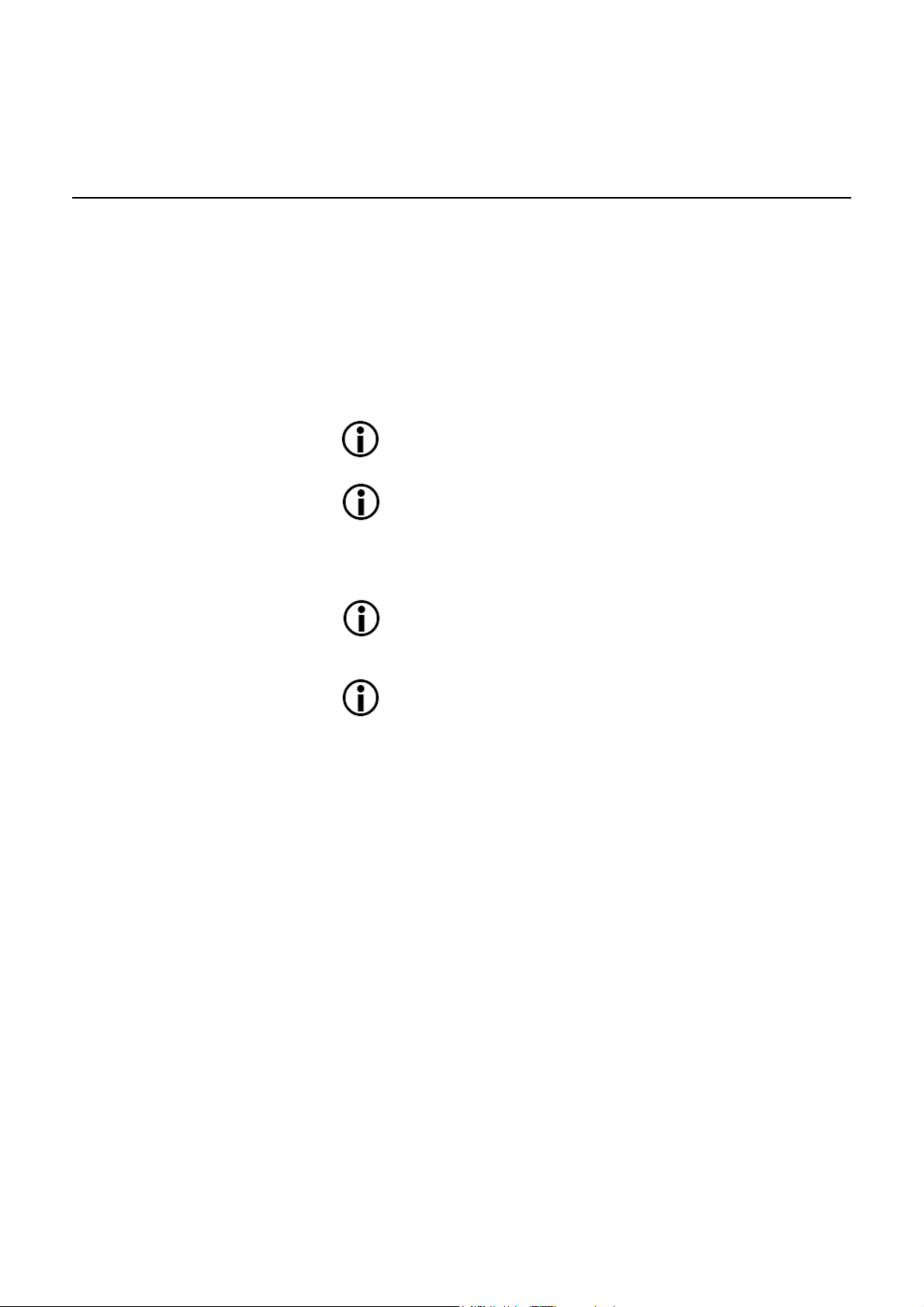
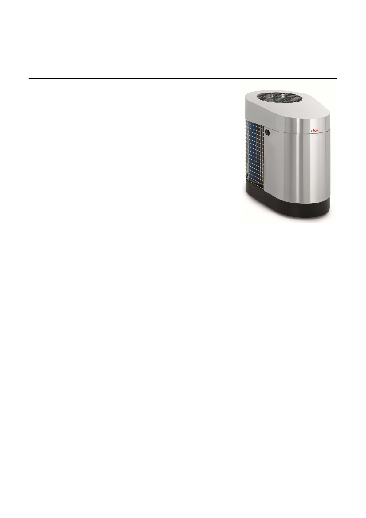
AEROTOP G Air-Water Heat Pump
for installation outdoors
06/2015 Art. No. 420010405804

Table of Contents
TABLE OF CONTENTS………………………….………………………………………………………….............................. 2
GENERAL INFOMATION…………………...................................................................................................................... 3
Safety wornings………………………………………............................................................................................ 4
Legal guidelines, warranty conditions, checks on delivery................................................................................ 6
Product Overview………………………………………………………………………………………………...…….. 7
Equipment……….………………………………………………………………………………………………...…….. 8
TECHNICAL DATA…………………………………………………………………………………………………………….….. 9
AEROTOP G07-10, G12, G07-14M………....................................................................................................... 9
AEROTOP G07(X)-10(X)……………................................................................................................................ 12
Performance chart AEROTOP G07(X)………................................................................................................... 15
Performance chart AEROTOP G10(X)………................................................................................................... 16
Performance chart AEROTOP G12………………………………………….…..……........................................... 17
Performance chart AEROTOP G07-14M (Nominal Capacity)…………………………………………….............. 18
Performance chart AEROTOP G07-14M (Maximum Capacity)…………………………………………............... 19
Operational limits …………………..................................................................................................................... 20
Device dimensions ……………………………………………………………………………………………............. 21
Delivery pressure circulating pump YONOS PARA RS 25/7.5……………………………………...…................. 22
Delivery pressure circulating pump STRATOS PARA 25/1-9........................................................................... 23
INSTALLATION………………………………………………………………………………………………………………..….. 24
Transportation, General installation notes………………………………………………………………………..….. 24
Pedestal………………………………………………………………………………………………………..………… 25
Pipeline, Condensate drain pipe……………………………………………………………………………….……… 26
Checklist for correct set-up…………………………………………………………………………………..………… 27
Delivery to installation site................................................................................................................................. 28
Hydraulic connections....................................................................................................................................... 30
Hydraulic connections, assembly instructions................................................................................................... 31
Notes……………………………………………………………………………………………………………….…….. 32
Electrical Connection ……………………………………….………………………………………………………….. 34
Instruction for the installation of control unit…………………………………………………………………...…….. 35
Electrical panel AEROTOP G………………………………………………………………………………….……… 37
Electrical panel AEROTOP G..X………………………………………………………………………………..…….. 38
Electrical panel AEROTOP G07-14M………………………………………………………………………….……… 39
Cabled components AEROTO G..(X)……………………………………………………………………………….... 40
Cabled components AEROTO G07-14M……………………………………………………………………….…….. 41
COMMISSIONING………………………………………………………………………………………………………...……… 42
Requirements and parameterization…………………………………………..……………………………...……… 42
Washing and filling, Water quality……………................................................................................................... 43
Checklist............................................................................................................................................................ 44
Sensor characteristic curves…………………………………………………………............................................... 46
MAINTENANCE……………………………………………………………………………………………………………..……. 49
General, cleaning.............................................................................................................................................. 49
Troubleshooting................................................................................................................................................. 50
PRODUCT FICHES ERP…………………………………………………………………………………………………….…. 53
PRODUCTS INFORMATION ERP ……………………………………………………………………………………….……. 54
CONFORMITY DECLARATION..................................................................................................................................... 56
NOTES………………………………………….................................................................................................................. 57
General notes.................................................................................................................................................... 3
2
General information
General notes
•
All calculations, sizing, installations
and commissioning linked to the
products described in this document can be carried out only by
qualified experts.
•
Please comply with local legal instructions, which may differ from
the directions given in this document.
•
Reserving the right to make
amendments.
Low energy consumption
The decision of opting for heat pump
heating is a significant contribution to
the protection of the environment
through the reduction of emissions
and the reduced use of primary energy.
In order for your new heating system
to function efficiently, please observe
the following:
The heat pump system must
be sized and installed with
great care.
Avoid excessively high inlet
temperatures. The lower the
inlet temperature on the heating water side, the more efficient the heat pump's operation.
Please comply with the correct setting up of the regulator, which must match the
heating system installed.
Preference should be given
to intense and short airing of
rooms, as opposed to always
open windows in the tilted
position; quick and immediate
airing reduces energy consumption.
3
General information
Safety warnings
Legend
The following general safety notes
are used in these operating instructions:
Please observe notes about
the function and mode of
operation.
Please do not fail to observe
the safety information.
Reference to the operating
instructions LOGON B WP61
controller
It is essential to read the instructions
carefully before installing the heat
pump. This is for your own safety and
that of others.
Keep this manual and keep it available .
For any questions related to the safety or if the assembly instructions are
not clear , please contact your local
sales office ELCO
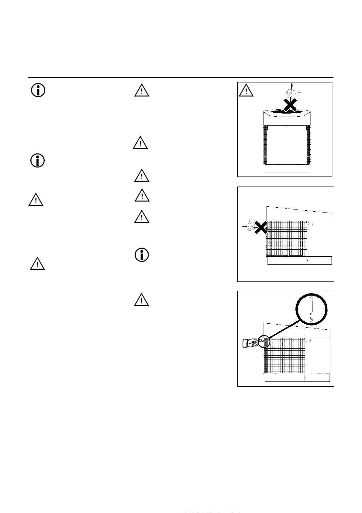
Keep the work area clean and free of
obstructions
Ensure appropriate lighting of your
workplace .
Unauthorized persons , children and
pets should be kept away from work
areas .
Keep antifreeze or heat transfer fluid
away from children and pets .
Do not insert objects through the air
grate devices .
Use only suitable components for
system ELCO.
In general , use only original spare
parts Elco . Check that materials and
components, before being used, comply with the laws, regulations , directives and national regulations .
Do not make unauthorized changes .
This can cause danger to personal
safety and damage to the plant . If
damage is evident that the machine
can not be operated
Personnel Requirements
Positioning, installation, connection
and commissioning of the heat pump
must be carried out by a specialised
expert in compliance with national
appliance regulations and with the
instructions for use.
Any work on the cooling circuit can
only be carried out by skilled personnel trained and experienced in the
risks linked to the use of coolants.
Observe the national standards for
the use of F-Gas , as well as EU directives CE 303/2008 and CE
842/200.
Workwear
Wear protective clothing, safety glasses , safety shoes and helmet dring
assembly works .
Use clothes that can not get caught in
moving parts. The same applies to
accessories, such as chains .
If your eyes come in contact with Refrigerant fluid , rinse eyes thoroughly
with running water and go immediately to a doctor.
Before opening the appliance, make
sure you disconnect all electrical circuits.
Fire protection .
In particular
- When passing through ceilings and
walls
- ( Observe local regulations ) In
rooms with special requirements for
fire prevention measures;
comply exactly the rules of fire safetyregulations and the applicable building regulations .
Take extra precautions when dealing
with open flames .
The appliance is not designed
to be used by individuals
(including children) whose
physical, sensory or mental
capabilities are reduced, or
lacking expertise or
knowledge, unless they have
been supervised or instructed
on how to use the appliance
by a person in charge of their
safety.
Please supervise children to
ensure they don't play with
the appliance.
4
General information
Safety warnings
Area of use
The AEROTOP G heat pump
is designed exclusively for
heating and the production of
potable hot water.
The heat pump can be integrated in newly installed or
existing heating systems by
complying with the operational limits.
In order to ensure trouble-free
operation
of the heat pump, we recommend that
you set up a service contract.
The setup, installation, configuration, and commissioning of
the heat pump system must
be carried out by a qualified
technician in observance of
the relevant statutory rules,
regulations, and guidelines,
as well as the operating instructions.
The use of the heat pump
must be registered with the
local power supply company.
Do not tilt the heat pump more
than 15° when transporting.
Avoid exposing the heat pump
to any type of moisture or humidity. Protect the heat pump
against damage and dirt during all stages of assembly.
The components and the pipes
of the cooling circuit should
never be used for transport
purposes.
The heat pump is fastened to
the transport pallet.
All electric circuits must be
de-energized before opening
the unit.
All work on the cooling circuit
must be carried out by trained
technicians who are familiar
with and trained in the use and
handling of the coolant.
Never use abrasive, acidic or
chlorine containing cleansers
on the surface of the equipment.
For cleaning , it’s recommended using a damp cloth.
The manufacturer declines all
responsability for the misuse
of the heat pump
5
General information
Legal guidelines, warranty conditions,
checks on delivery
General indications
The sizing, installation, commissioning and maintenance of
the products described in this
document can only be carried
out by qualified specialists.
Please comply with local legal
instructions, which may differ
from the directions given in this
document.
These instructions are necessary to
correctly install, adjust and maintain
the appliance. It is therefore essential
to read the following instructions carefully and to have the heat pump installed, tested and maintained by
qualified technicians with specific
training.
At the end of the period of warranty,
the manufacturer declines all responsibility for mechanical, hydraulic or
electrical modifications. In the event
of explicitly unauthorised interventions, carried out in breach of these
instructions, the warranty shall be
forfeit with immediate effect.
During installation, the specific operating safety regulations must be complied with. Please check that the properties of the power supply match the
heat pump details (identification tag).
These instructions and the heat
pump's electrical system must be
stored with due care and attention
and, if necessary, made available to
the relevant personnel.
The manufacturer declines all
responsibility for damages to
individuals and property
caused, directly or indirectly, by
failure to comply with these
instructions.
The appliance body can only be
opened by a qualified technician.
Binding indications and directives
The construction and manufacture of
the heat pump complies with all European regulation directives (see EC
declaration of conformity).
The power connection of the
heat pump must be carried out
in compliance with national
appliance regulations. In addition, it is necessary to comply
with the connection conditions
of the local energy provider.
Additional indications and instructions.
Functional or surface-ready heating
with the heat pump according to DIN
EN 1264 is only possible if taking into
account the aforementioned conditions.
After sizing the heat pump for normal operations, it may not be possible to generate all heating neces-
sary.
Please comply also with the following
instructions:
•
Comply with regulations and instructions issued by the screed
manufacturer of the screed mortar!
•
Correct operations are possible
only with a system that has been
installed up to standards
(hydraulics, electrical components,
settings)! Otherwise the screed
could be damaged!
Because overloading could
cause serious damages, it is
forbidden to activate the heat
pump if the following conditions
apply:
•
construction drying out;
•
System temperature < 25 °
C . It is recommended to
heat with the use of electrical
resistance installed
•
unfinished system
(raw construction);
•
external doors and windows
not completed and closed.
In these cases, it is necessary
to make provisions for site
heating.
Warranty terms
The warranty for heat pumps is valid
for 24 months from the day of delivery. For everything else, the sale,
provision and warranty conditions
apply on the basis of the order confirmation.
Our warranty provisions shall be forfeit for damages as a result of:
•
improper use, misuse or noncompliant use
•
incorrect installation or commissioning by the purchaser or third
parties
•
addition of parts from other manufacturers
•
usage of the system with excessive pressure or pressure outside
the indicated factory levels
•
failure to comply with the instructions contained in the manual
Checks on delivery
The appliances are delivered on a
wooden pallet, packed in cardboard.
At the time of delivery, please check
that the appliance wasn't damaged in
transport and that the equipment is
complete.
If you do find any damage, this
must be reported immediately on
the transport document with the
following wording: «Delivery accepted with reserved due to obvious damages».
The utmost care has been used in
manufacturing the heat pump.
However, during the manipulation of
the evaporator, it isn't possible to exclude a slight bending of the single
blades during production. This does
not constitute a defect in the product.
For more information, please see
product description: high-efficiency
visible evaporator.
6
General information
Product Overview
Models available
The AEROTOP G heat pumps are
available in the following models, all
powered by electricity.
400V/3ph/50Hz
AEROTOP G07
AEROTOP G10
AEROTOP G12
AEROTOP G07-14M
230V/1ph/50Hz
AEROTOP G07X
AEROTOP G10X
Construction/Functions
•
Air-water heat pump for external installation.
•
Adjustable power (only Aerotop
G07-14M)
•
For the production of hot water
for heating systems and domestic water supply.
•
Inlet temperature up to 65 °C.
•
High-efficiency circulation pump.
•
Low noise emission thanks to
the ELCO-NRS system (Noise
Reduction System).
•
Cycle-inversion defrosting function, with high efficiency as
based on actual demand.
•
Multiple-stage emergency heating element.
Structure
•
Stainless steel or plastic covering (colored Stainless steel)
•
Completely soundproofed and
thermally isulated
•
Easy removal of all panels for
ease of handling.
•
The machine itself stands on
rubber buffers.
Compressor
• Hermetic scroll with low level
noise and vibrations.
•
Speed control via inverter to
adjust heat to the actual demand in all conditions, both for
heating and optimal production
of hot domestic water
(AEROTOP G07-14M).
Condenser
•
High-efficiency plate heat exchanger in stainless steel.
•
Water cooling on heating side.
•
Fully thermally insulated.
Evaporator
•
Heat exchanger with wide passage surface, with optimised air
flow, built with copper pipes with
aluminium fins.
•
The fins have a hydrophilic cover for better down flow of condensation and optimised defrosting.
Cooling circuit
•
Hermetically sealed, loaded at
the factory and tested against
leaks.
•
Ecologic coolant R407C.
•
The coolant complies with the
Kyoto protocol requirements.
Fan
•
Low noise Axial fan.
•
Variable speed.
•
Low power consumption.
Control
•
Front mounted LOGON® E
WP61 heating regulator.
•
Management of PV panels.
•
Complies with the requirements
of the SG-ready label.
•
Easy configuration menu with
pre-configured hydraulic
schemes.
•
Management of the generator
block.
•
1 direct heating circuit, up to 2
mixing circuits (accessories
required) and domestic hot water loading.
•
Backlit display with easy to read
text and display of statuses and
functions.
•
Predefined setpoints and heating programmes.
•
Automatic change from summer
operation to winter operation
and vice versa.
•
Dedicated programmes for every heating circuit and hot water.
•
Zone control can be connected
for every mixed circuit.
•
Legionella protection circuit for
thermal disinfection of drinking
water.
•
Multi-function outputs programmable for solar energy, domestic
hot water, room heating, circulating pump for hot water.
•
Control of a second heat generator.
•
Swimming pool integration.
•
Integration of a combustion fuel
boiler.
•
Storage tank management.
•
Cascade control.
Electrical panel
•
Internal wiring in compliance
with current directives.
•
Equipped with all safety components necessary:
•
Possibility of installing additional
expansion modules.
•
Circuit breaker 400V and 230V.
7
General information
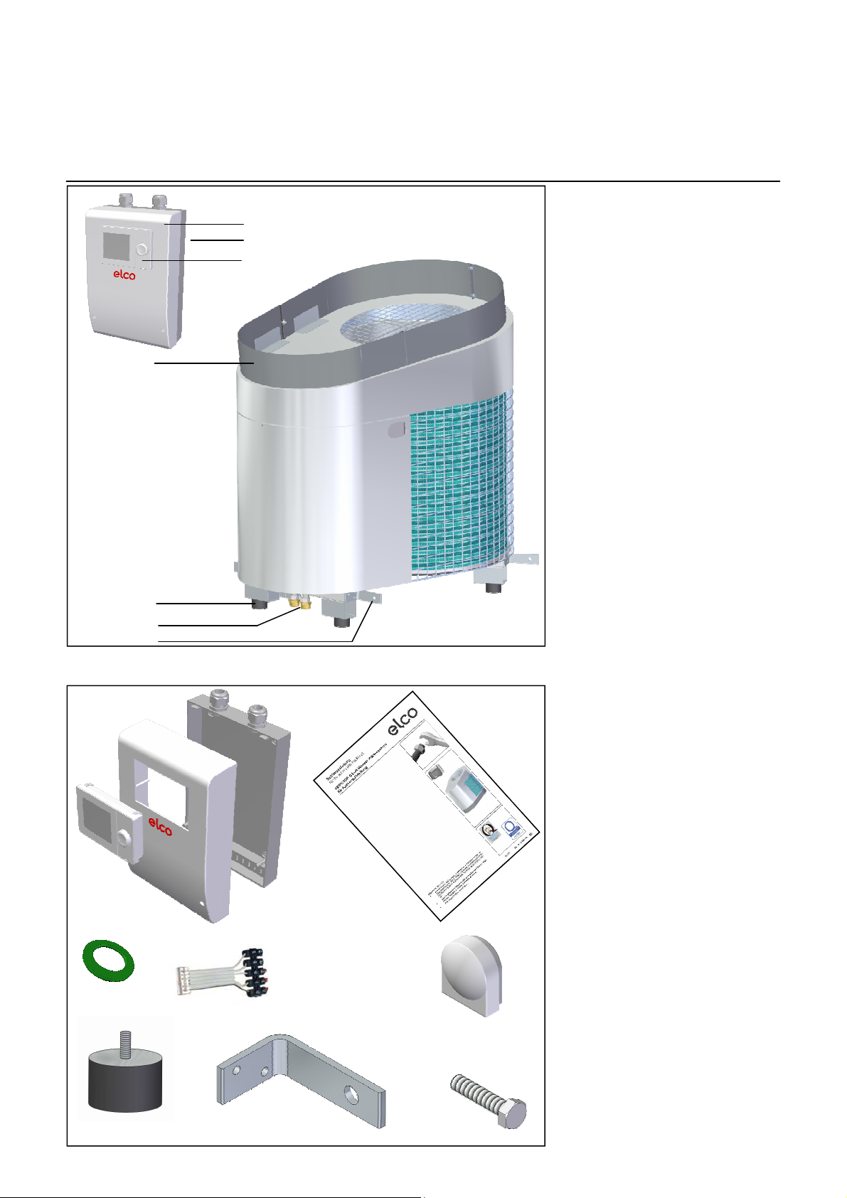
Equipment
11
1
2
3
6
8
9
The following components are
included with the delivery of the heat
pump:
1 1 control unit bracket
2 1 switch panel
3 1 control unit to the controller
4 1 outdoor sensor
5 4 vibration absorbent adjustable
feet
6 4 hose seals
7 1 set of documentation
8 2 vibration absorbent hoses
9 4 transport aids (L-sections)
10 8 M10 bolts for securing the
transport aids
11 1 base
12 1 Flat cable
2
7
3
1
12
6
4
5
9
10
8
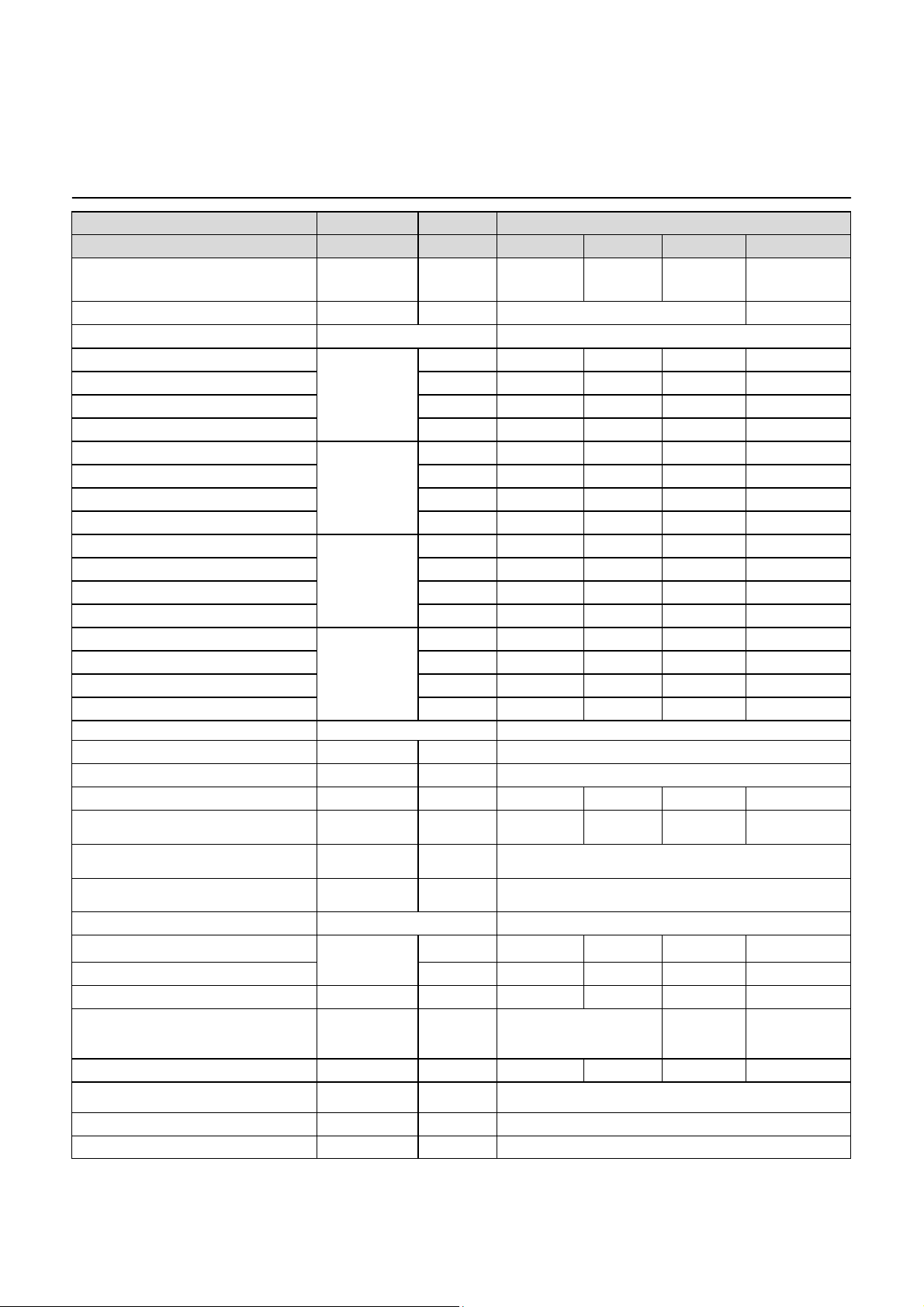
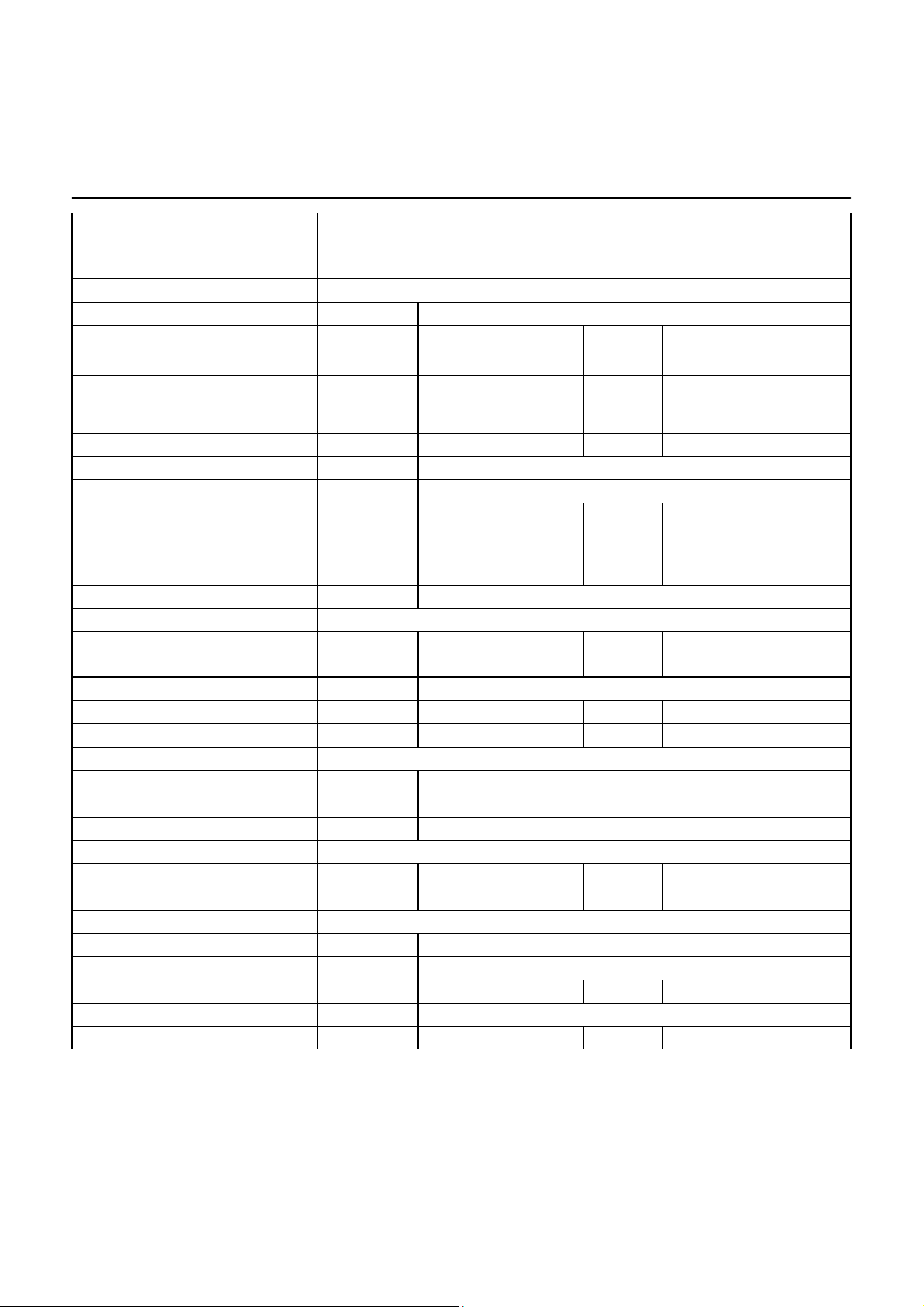
Technical Data
AEROTOP G07 / G10 / G12 / G07-14M
Series
Model
Energy efficiency category, average
climate, W55/W351)
Power regulation
Heating
Capacity range min-max
Nominal heating capacity [kW] 8.64 12.52 14.1 11.0
Nominal power input [kW] 1.85 2.69 3.33 2.2
COP 4.65 4.65 4.23 5.0
Capacity range min-max
Nominal heating capacity [kW] 6.36 9.22 11.8 10.0
Nominal power input [kW] 1.72 2.5 3.24 2.6
COP 3.69 3.69 3.64 3.8
Capacity range min-max
Nominal heating capacity [kW] 5.30 7.60 10.30 10.7
Nominal power input [kW] 1.70 2.50 3.10 3.6
COP 3.10 3.10 3.30 2.9
Capacity range min-max
Nominal heating capacity [kW] 5.00 7.30 9.80 10.8
Nominal power input [kW] 2.40 3.50 4.40 5.7
COP 2.10 2.10 2.20 1.9
Evaporator, air side
Evaporator Grooved copper pipes and fins in hydrophilic aluminium
Fan Axial
Air flow min-max [m³/h] 3500 4000 4600 2800-5200
(2)
A7/W35
A2/W35
A-7/W35
A-7/W55
G07 G10 G12 G07-14M
A++/A++ A++/A++ A++/A++ A++/A++
[kW] 8.64 12.52 14.1 4,7 - 17,5
6.36 9.22 11.8 3,6 - 15,2
5.30 7.60 10.30 2.9 - 12.7
2,9 - 12,8
AEROTOP G
No Yes
Available static pressure (without Pa 47 45 41 34-55
Min external air temperature in hea- [°C] -18
Max external air temperature in hea- [°C] 35
Condenser, water side
Nominal water flow (dT=5K)
Nominal pressure drop (dT=5K) [mbar] 128 218 350 250
Minimum water flow [m³/h] 0.76 1.08 1.37 0.97
Circulator model YONOS PARA 25/7.5
Available pressure head [mbar] 576 370 254 382
3-way water valve integrated No
Max operating pressure [bar] 3
Plate heat exchanger material AISI 316
1) Note on the energy efficiency category: This information complies with the official requirements for room heaters (EU regulation no. 811/2013) that will
be mandatory as of September 2015, based on the data for heating heat pumps as per EN 14511 and EN 14825.
2) According to EN 14511, EN 14825According to EN 14511, EN 14825
(2)
A2/W35
[m³/h] 1.52 2.09 2.80 1.93
STRATOS
PARA 25/1-
9
YONOS PARA
25/7.5
9
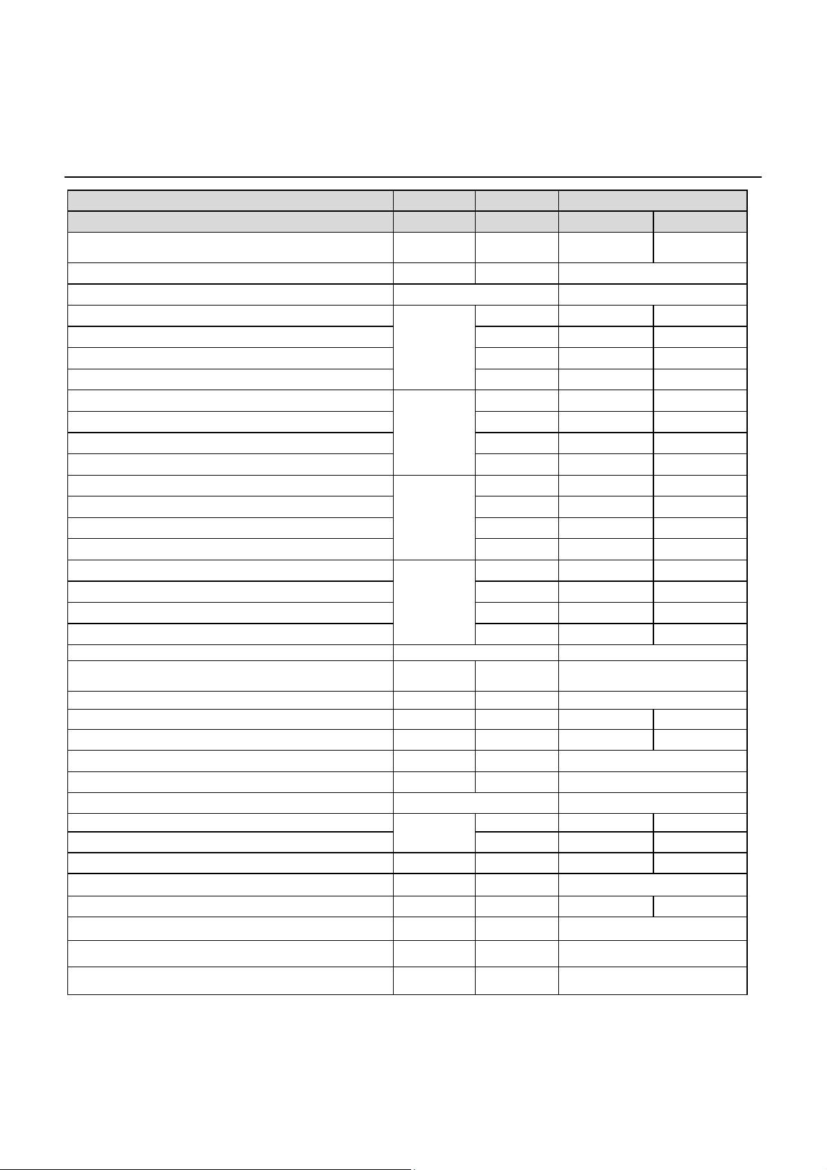
Technical Data
AEROTOP G07 / G10 / G12 / G07-14M
-18°C / 45°C
Operating limits air / water (heating)
Electrical data
Voltage supply
Current consumption max
@A35Wmax
(without heating element)
Nominal current consumption
@A2W35
Inrush current VSA [A] 13 20.5 25.3 < 6
Starting current with locked rotor LRA [A] 32 51.5 64 -Max starts per hour max. 3
Restart delay after power off [Sec] 60-120
I max. [A] 5.2 8.2 10.1 16.5
I [A] 3.1 4.8 5.9 6.7
[°C]
-7°C / 57°C
-4°C / 60°C
35°C / 60°C
3/N/PE 400 V/50 Hz
External fuse (without heating element)
External fuse heating element (6 kW) [A] C16A 3-polig
Control voltage supply 230V/50Hz
Power input data
Heat pump max power input
(without heating element)
Heating element power input PE [kW] 2/4/6 selectable
Fan power input min-max PV [W] 30 40 50 10-60
Circulator power input min-max PP [W] 4-75 4-75 3.5-90 4-75
Dimensions
Height [mm] 1140-1290
Width [mm] 960
Depth [mm] 1470
Weights
Stainless steel version [kg] 248 260 262 255
Plastic version [kg] 233 245 247 240
Refrigerant circuit
Compressor Hermetic scroll
Refrigerant R407C
Refrigerant charge [kg] 3.8 4.0 5.5 4.6
Lubricant Ester oil
Lubricant quantity l 1.5 1.9 1.9 0.9
[A] C13A 3-polig
PHP [kW] 3.17 5.28 6.16 8.20
C16A 3-
polig
C20A 3-
polig
C20A 3-
polig
C25A 3-
polig
C20A 3-polig
C25A 3-polig
10

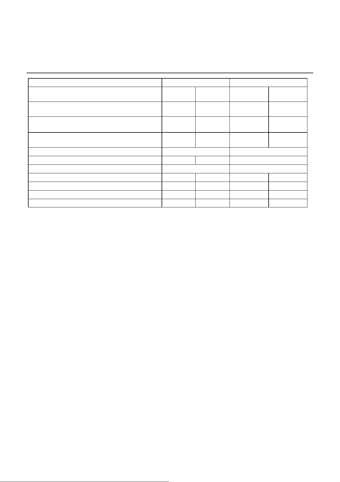
Technical Data
AEROTOP G07 / G10 / G12 / G07-14M
Sound measurements
Sound power level Lwa 3)
(nominal power)
Sound power level Lwa 3)
(nominal power, silence mode)
Sound pressure level Lpa, free field
( at 1 m )
Sound pressure level Lpa free field
( at 1 m; silence mode )
Controller
Model LOGON B WP 61
Connections
Water inlet DN25 (IG 1) DN25 (IG 1) DN25 (IG 1) DN25 (IG 1)
Heating water outlet DN25 (IG 1) DN25 (IG 1) DN25 (IG 1) DN25 (IG 1)
Condensation discharge DN25 (IG 1) DN25 (IG 1) DN25 (IG 1) DN25 (IG 1)
Power supply 1 x 35mm 1 x 35mm 1 x 35mm 1 x 35mm
A7 / W35 dB(A) 57 59 61 55
A7 / W35 dB(A) 49 51 53 47
53 55 57
45 47 49
3) Sound power level Lwa according to EN 12102
11
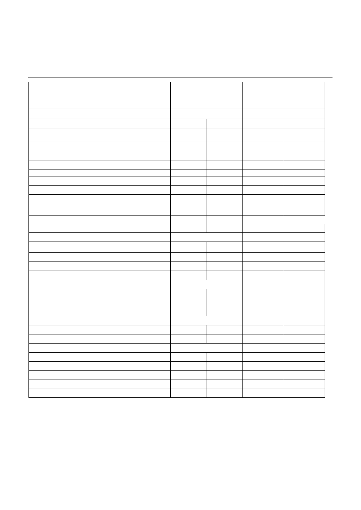
Technical Data
AEROTOP G07X / G10X
Series
Model
Energy efficiency category, average climate, W55/
W351)
Power regulation No
Heating
Capacity range min-max
Nominal heating capacity [kW] 8.64 12.52
Nominal power input [kW] 1.85 2.69
COP 4.65 4.65
Capacity range min-max
Nominal heating capacity [kW] 6.36 9.22
Nominal power input [kW] 1.72 2.5
COP 3.69 3.69
Capacity range min-max
Nominal heating capacity [kW] 5.30 7.60
Nominal power input [kW] 1.70 2.50
COP 3.10 3.10
Capacity range min-max
Nominal heating capacity [kW] 5.00 7.30
Nominal power input [kW] 2.40 3.50
COP 2.10 2.10
Evaporator, air side
Evaporator
Fan axial
Air flow min-max [m³/h] 3500 4000
Available static pressure (without ducts) Pa 47 45
Min external air temperature in heating [°C] -18
Max external air temperature in heating [°C] 35
Condenser, water side
Nominal water flow (dT=5K)
Nominal pressure drop (dT=5K) [mbar] 128 218
Minimum water flow [m³/h] 0.76 1.08
Circulator model YONOS PARA 25/7.5
Available pressure head [mbar] 576 370
3-way water valve integrated No
(2)
(2)
A++/A++ A+/A++
[kW] 8.64 12.52
A7/W35
6.36 9.22
A2/W35
5.30 7.60
A-7/W35
A-7/W55
Grooved copper pipes and fins in
A2/W35
[m³/h] 1.52 2.09
AEROTOP G
G07X G10X
hydrophilic aluminium
Max operating pressure [bar] 3
Plate heat exchanger material AISI 316
1) Note on the energy efficiency category: This information complies with the official requirements for room heaters (EU regulation no. 811/2013) that will
be mandatory as of September 2015, based on the data for heating heat pumps as per EN 14511 and EN 14825.
2) According to EN 14511, EN 14825According to EN 14511, EN 14825
12
Technical Data
AEROTOP G07X / G10X
-18°C / 45°C
Operating limits air / water (heating)
Electrical data
Voltage supply 3/N/PE 400 V/50 Hz
Current consumption max @A35Wmax
(without heating element)
Nominal current consumption @A2W35 I [A] 16.2 25
Inrush current VSA [A] 40.5 75
Starting current with locked rotor LRA [A] 76 108
Max starts per hour max. 3
Restart delay after power off [Sec] 60-120
External fuse (without heating element) [A] C13A 1-polig C16A 1-polig
External fuse heating element (2kW) C32A 1-polig C40A 1-polig
I max. [A] 5.2 8.2
-7°C / 57°C
-4°C / 60°C
35°C / 60°C
External fuse heating element (4 kW) C40A 1-polig C50A 1-polig
External fuse heating element (6 kW) [A] C50A 1-polig C63A 1-polig
Control voltage supply 230V/50Hz
Power input data
Heat pump max power input (without heating element) PHP [kW] 3.17 5.3
Heating element power input PE [kW] 2/4/6 selectable
Fan power input min-max PV [W] 30 40
Circulator power input min-max PP [W] 4-75 4-75
Dimensions
Height [mm] 1140-1290
Width [mm] 960
Depth [mm] 1470
Weights
Stainless steel version [kg] 248 260
Plastic version [kg] 233 245
Refrigerant circuit
Compressor Hermetic scroll
Refrigerant R407C
Refrigerant charge [kg] 3.8 4.0
Lubricant Ester oil
Lubricant quantity l 1.5 1.9
13
Technical Data
AEROTOP G07X / G10X
Sound measurements
Sound power level Lwa 3)
(nominal power)
Sound power level Lwa 3)
(nominal power, silence mode)
Sound pressure level Lpa, free field ( at 1 m ) A7 / W35
Sound pressure level Lpa, free field ( at 1 m; silence
mode )
Controller
Model
Connections
Water inlet
Heating water outlet
Condensation discharge
Power supply
A7 / W35 dB(A)
LOGON B WP 61
DN25 (IG 1) DN25 (IG 1)
DN25 (IG 1) DN25 (IG 1)
DN25 (IG 1) DN25 (IG 1)
1 x 35mm 1 x 35mm
57 59
53 55
dB(A)
49 51
45 47
3) Sound power level Lwa according to EN 12102
14

Technical Data
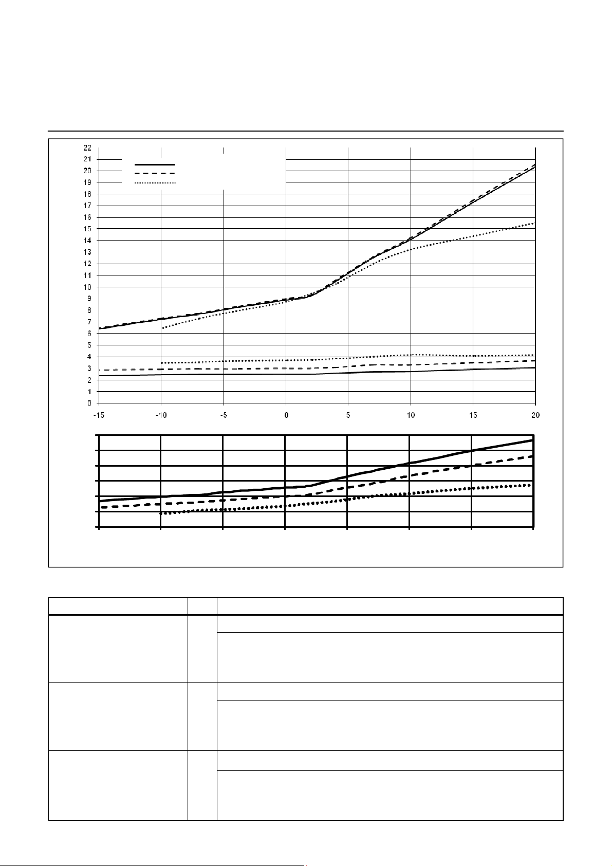
Performance chart AEROTOP G07(X)
Flow temperature 35°C
Flow temperature 45°C
Flow temperature 55°C
Q
h
P
Power consumption and heating capacity in kW Performance rating in heating mode
7
b
6
e
i
r
t
e
b
5
z
i
e
H
4
m
i
l
3
h
a
z
s
2
g
n
u
t
s
1
i
e
L
-15 -10 -5 0 5 10 15 20
Lufteintrittstemperatur (°C)
Air inlet temperature (°C)
HEATING CAPACITY
External air temperature °C -15 -10 -7 2 7 10 15 20
Outlet water temperature °C
35
Heating capacity kW 4.41 4.98 5.28 6.36 8.64 9.73 11.91 14.03
Power consumption kW 1.64 1.67 1.70 1.72 1.86 1.89 2.00 2.10
COP 2.69 2.98 3.10 3.69 4.66 5.16 5.96 6.68
el
Outlet water temperature °C
45
Heating capacity kW 4.45 5.03 5.33 6.43 8.70 9.82 12.03 14.17
Power consumption kW 1.97 2.01 2.05 2.07 2.27 2.26 2.40 2.52
COP 2.26 2.51 2.61 3.11 3.83 4.34 5.02 5.62
Outlet water temperature °C
55
Heating capacity kW - 4.45 5.03 6.51 8.27 9.13 9.92 10.71
Power consumption kW - 2.38 2.43 2.57 2.75 2.86 2.82 2.86
COP - 1.87 2.07 2.53 3.01 3.19 3.52 3.74
15
Technical Data
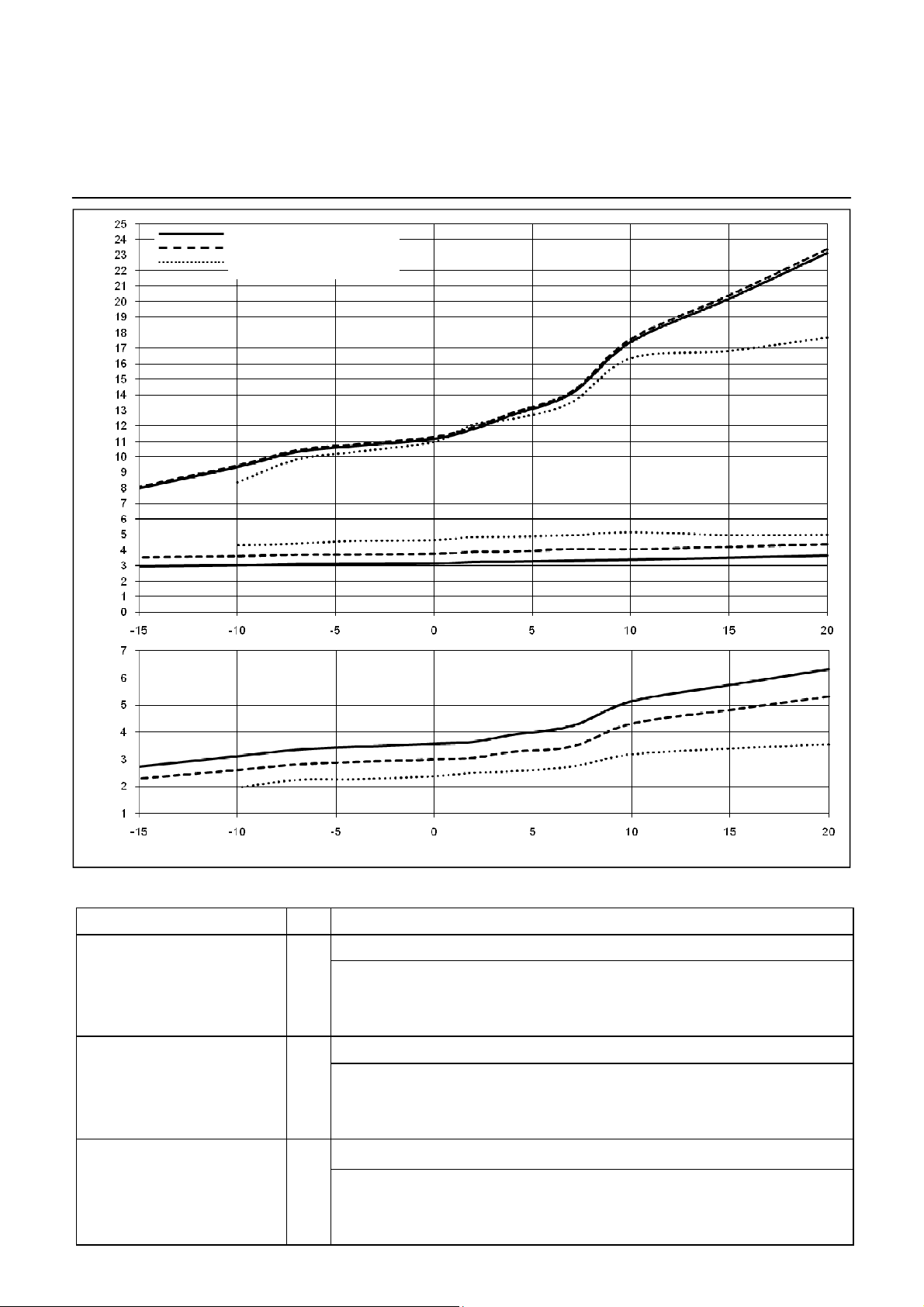
Performance chart AEROTOP G10(X)
Flow temperature 35°C
Flow temperature 45°C
Flow temperature 55°C
Q
h
Power consumption and heating capacity in kW Performance rating in heating mode
7
6
5
4
3
2
1
-15 -10 -5 0 5 10 15 20
Lufteintrittstemperatur (°C)
Air inlet temperature (°C)
External air temperature °C -15 -10 -7 2 7 10 15 20
Outlet water temperature °C
Heating capacity kW 6.39 7.22 7.65 9.22 12.52 14.10 17.27 20.34
Power consumption kW 2.37 2.42 2.47 2.50 2.69 2.73 2.90 3.05
COP 2.69 2.98 3.10 3.69 4.65 5.16 5.96 6.68
HEATING CAPACITY
35
P
el
Outlet water temperature °C
Heating capacity kW 6.45 7.29 7.73 9.32 12.60 14.24 17.44 20.54
Power consumption kW 2.85 2.91 2.96 3.00 3.29 3.28 3.48 3.66
COP 2.26 2.51 2.61 3.11 3.83 4.34 5.02 5.62
Outlet water temperature °C
Heating capacity kW - 6.45 7.29 9.44 11.99 13.23 14.38 15.52
Power consumption kW - 3.45 3.52 3.72 3.99 4.15 4.08 4.15
COP - 1.87 2.07 2.53 3.01 3.19 3.52 3.74
16
45
55
Technical Data
Performance chart AEROTOP G12
Flow temperature 35°C
Flow temperature 45°C
Flow temperature 55°C
Q
h
Power consumption and heating capacity in kW
Performance rating in heating mode
External air temperature
Outlet water temperature
Heating capacity
Power consumption
COP
Outlet water temperature
Heating capacity
Power consumption
COP
Outlet water temperature
Heating capacity
Power consumption
COP
Air inlet temperature (°C)
HEATING CAPACITY
°C -15 -10 -7 2 7 10 15 20
°C
kW 7.99 9.36 10.32 11.80 14.10 17.40 20.19 23.14
kW 2.94 3.01 3.09 3.24 3.33 3.39 3.52 3.66
2.72 3.11 3.35 3.64 4.23 5.13 5.74 6.32
°C
kW 8.07 9.45 10.43 11.92 14.20 17.57 20.39 23.37
kW 3.52 3.61 3.70 3.89 4.08 4.07 4.22 4.39
2.29 2.61 2.82 3.07 3.48 4.32 4.83 5.32
°C
kW - 8.36 9.84 12.08 13.51 16.33 16.82 17.67
kW - 4.28 4.40 4.83 4.94 5.15 4.96 4.98
- 1.95 2.24 2.50 2.73 3.17 3.39 3.54
35
45
55
P
el
17
Technical Data
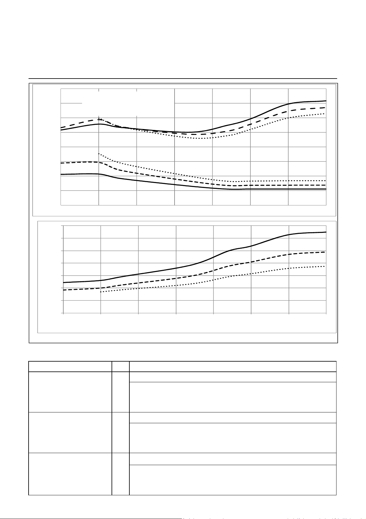
Performance chart AEROTOP G07-14M (Nominal Capacity)
16
14
12
10
————
- - - - - - …………..
8
6
Flow temperature 35°C
Flow temperature 45°C
Flow temperature 55°C
Q
h
4
Potenza assorbita e potenza termica (kW)
2
Power consumption and heating capacity in kW
0
-15 -10 -5 0 5 10 15 20
7
6
5
4
3
2
1
Coefficiente di rend. regime riscaldamento
0
Performance rating in heating mode
-15 -10 -5 0 5 1 0 15 20
Air inlet temperature (°C)
Temperatura ingresso aria (°C)
External air temperature °C -15 -10 -7 2 7 10 15 20
NOMINAL CAPACITY
P
el
Outlet water temperature °C
35
Heating capacity kW 10.33 11.14 10.67 10.02 10.98 11.85 13.90 14.34
Power consumption kW 4.23 4.27 3.64 2.61 2.20 2.21 2.21 2.21
COP 2.44 2.61 2.93 3.84 4.98 5.37 6.28 6.49
Outlet water temperature °C
Heating capacity kW
10.65 11.75 10.76 9.74 10.18 11.11 12.91 13.42
45
Power consumption kW 5.79 5.87 4.76 3.29 2.70 2.72 2.74 2.75
COP 1.84 2.00 2.26 2.96 3.76 4.09 4.7 4.89
Outlet water temperature °C
Heating capacity kW
- 11.96 10.76 7.65 9.55 10.40 11.98 12.60
55
Power consumption kW - 7.06 5.75 3.33 3.28 3.30 3.35 3.36
COP - 1.69 1.87 2.30 2.91 3.15 3.58 3.75
18
 Loading...