

Page 1

Operation Manual
for the authorized specialist
Oil Burner
EK 6../7../8../9.. L-E
03/2005 102.880.2006
Page 2
2
Inhalt
Overview Contents ...........................................................................................................2
Overview Important Information Warranty Product Description .......................................3
Technical Data .................................................................................................4
Dimensioned Drawings ....................................................................................9
Operation Start-up Mode Oil Operating Mode General Safety Functions .......................12
Fuel-air Compound Control Hydraulic Diagram .............................................13
Hydraulic Diagram L-E / GL-E Burner EK 6 - EK 9 ........................................14
Operation Hydraulic Valves and Instruments Group .......................................................15
Start-up Burner Head Settings .....................................................................................16
Installation Mounting to Boiler Electrical Connection Presetting ......................................19
Installation Boiler lining for Burner L-R/E .........................................................................20
Oil Connection Oil Pressure Control (Feed) ...................................................21
Start-up Return Nozzle Rod Type RDN Burner Type EK 6 .........................................22
Start-up Nozzle Selection, Type W2-50° ........................................................... ...... ....23
Start-up Return Nozzle Rod RDG 1250 Burner EK 7... - EK 9... .................................24
Nozzle selection „Sonic“ ..................... ..... ...... ....................................... ...... ....25
Checking Procedure .......................................................................................26
Adjusting Instructions Elektronic Burner Control with Electronic Compound Controller ....................27
Flame Detecting System Type FLW 05 .........................................................28
Servomotor Type SAD 15.0 ...........................................................................29
Electrical Actuator STM 40 .............................................................................30
Starting the BCS, Etamatic, VMS/FMS Electronic Compound Controller .....31
Adjusting Instructions Oil Pressure Switch (Option) Air Pressure Switch .........................................32
Operation Automatic Furnace Controller LAL... / LOK... Regulator KS 92 ....................33
Adjusting Instructions Flame Monitor Sensor Current Measurement ...............................................34
Adjustment Fan Impeller ...................................................................................................35
Servicing Instructions Burner Maintenance .......................................................................................36
Exhaust Gas Test ...........................................................................................37
Trouble Shooting Instruction s ......................................................... ..... ...... ....38
Operating Trouble ............................................... ..... ......................................40
System Diagram .............................................................................................41
Overview
Contents
Page 3

3
Overview
Important Information
Warranty
Product Description
Important information
The burners of type EK 6.../ 7.../ 8.../
9...L-E have been designed for the
combustion of light fuel oil EL.
The burners should be installed and
taken into opera tion by qualifi ed pers onnel only who will be responsible for the
proper performance of this work in
accordance with the applicable regulations and guidelines.
Any repair work on monitors, limiters
and automatic furnace controllers and
on the other sa fety f aci lities are allowed
to be done only by the manufacturers
themselves or specialists authorized by
them. Original parts should only be
exchanged by a duly qualified specialist.
Standards and regula tion s
The following standard s sho ul d be
observed in the interest of a safe, easyon-the-environment and energy-saving
operation of the burner:
According to DIN 4755, the user must
be instructed in the ope rati on o f the burner.
For the installation of an oil furnace
system, care should be taken to
observe DIN 4755, TRbF (Technical
Regulation on Combustib le Liquids) and
the local furnace construction regulations applicable in the country.
Place of installation
The burner must not be operated in
rooms containing aggressive vapours
(e.g. spray, perchloroethylene, hydrocarbon tetrachloride, solvent, etc.) or
tending to heavy dust formation or high
air humidity.
Adequate ventilation must be prov id ed
at the place of installation of the furnace
system to ensure a reliable supply with
combustion air.
Maintenance
The furnace system should be serviced
at least once a year by an authorized
specialist. It is recommended to conclude a maintenance agreement to this
effect.
Warranty
Manufacturer will not accept any warranty if the operating instructions have
not been duly observed in the start-up
and maintenance of the burner and
damages have been caused by improper installation, incorrect adjustment,
unauthorized interference or operating
errors.
Product description
The burners of type EK 6.../EK 7.../EK
8.../EK9...L-E can be used for the combustion of light fuel oil EL according DIN
51603-1.
The burners are equipped with combustion air fan and air pr essure swit ch with
test key, windbox with actuator for the
air control dampers, oil pressure atomizer with oil high-pressure pump, nozzle
rod, return nozzle and oil hydraulics
block (with pressure sw it ches, valves
and control shaft), pressure hoses and
electric ignition system.
The burners are designed to operate
with an electronic compound control
system.
EN267/
DIN4787
Oil atomizer burners
VDE 0116 Electrical Equipment
of furnace
Page 4
4
Technical Data Sheet
Monoblock Oil Burner
EK 6.170 / 200 L-E
Technical Data
Burner output
Fuel flow rate
Operating mode
Type of fuel
Burner control box
Flame sensor
Fan motor
Pump unit
Gear output
Pressure
Nozzle rod
Nozzle
Oil hoses / External connection
Actuator
Ignition transformer
Weight
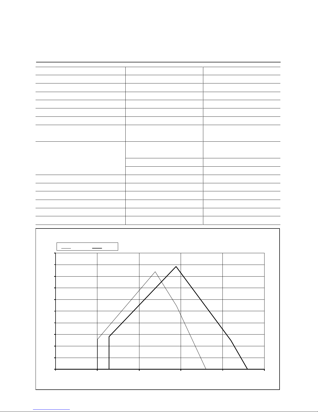
Operating range EK 6.170 / 200 L-E
0
2
4
6
8
10
12
14
16
18
20
0 500 1000 1500 2000 2500
6.170 L 6.200 L
Q Burner output [kW]
F
Air temperature 20°C, test values according to EN 267 (DIN 4787) at 171 m
above sea level
Pressure in
c
ombus
t
ion
c
hamb er [mb ar]
6.170 L-E
501 - 1800 kW
42 - 152 kg/h
fully modulating
Light oil EL
BCS / LAL 2 / LOK 16
QRB 3 / RAR 7
400 / 690 V, 50Hz
3,0 kW, 6,4 A, 2800 min-¹
SMG 1945 - 0,75 kW
520 l/h
30 bar
RDN
Thread 7/8"
DN 16 x 1500 / R 1/2"
SAD 15 / STM 40 / MM1004
150 kg
≈
ZA20 140 / ZM20-14
6.200 L-E
640 - 2300 kW
54 - 194 kg/h
fully modulating
Light oil EL
BCS / LAL 2 / LOK 16
QRB 3 / RAR 7
400 / 690 V, 50Hz
3,0 kW, 6,4 A, 2800 min-¹
SMG 1945 - 0,75 kW
520 l/h
30 bar
RDN
Thread 7/8"
DN 16 x 1500 / R 1/2"
SAD 15 / STM 40 / MM1004
150 kg
≈
ZA20 140 / ZM20-14
No.: 102.880.434203/05
Technical Data
EK 6.170 / 200 L-E
Page 5

5
Technical Data Sheet
Monoblock Oil Burner
EK 6.240 / 300 L-E
Technical Data
Burner output
Fuel flow rate
Operating mode
Type of fuel
Burner control box
Flame sensor
Fan motor
Pump unit
Gear output
Pressure
Nozzle rod
Nozzle
Oil hoses / External connection
Actuator
Ignition transformer
Weight
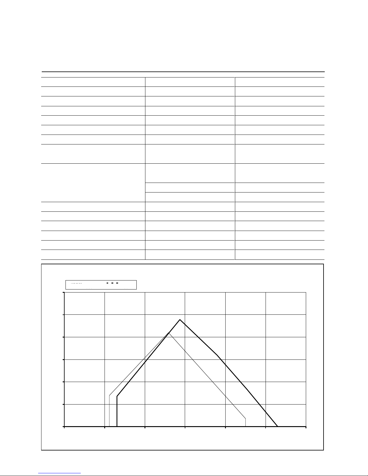
Operating range EK 6.240 / 300 L-E
0
5
10
15
20
25
0 500 1000 1500 2000 2500 3000 3500
6.240 L 6.300 L
Q Burner output [kW]
F
Air temperature 20°C, test values according to EN 267 (DIN 4787) at 171 m
above sea level
Pressure in
c
ombus
t
ion
c
hamb er [mb ar]
6.240 L-E
681 - 2500 kW
57 - 210 kg/h
fully modulating
Light oil EL
BCS / LAL 2 / LOK 16
QRB 3 / RAR 7
400 / 690 V, 50Hz
4,0 kW, 8,5 A, 2800 min-¹
SMG 16026 - 1,1 kW
735 l/h
30 bar
RDN
Thread 7/8"
DN 20 x 1500 / R 1/2"
SAD 15 / STM 40 / MM1004
160 kg
≈
ZA20 140 / ZM20-14
6.300 L-E
940 - 3250 kW
79 - 280 kg/h
fully modulating
Light oil EL
BCS / LAL 2 / LOK 16
QRB 3 / RAR 7
400 / 690 V, 50Hz
4,0 kW, 8,5 A, 2800 min-¹
SMG 16026 - 1,1 kW
735 l/h
30 bar
RDN
Thread 7/8"
DN 20 x 1500 / R 1/2"
SAD 15 / STM 40 / MM1004
160 kg
≈
ZA20 140 / ZM20-14
No.: 102.880.435303/05
Technical Data
EK 6.240 / 300 L-E
Page 6
6
Technical Data Sheet
Monoblock Oil Burner
EK 7... L-E
Technical Data
Burner output
Fuel flow rate
Operating mode
Type of fuel
Burner control box
Flame sensor
Fan motor
Pump unit
Gear output
Pressure
Nozzle rod
Nozzle
Oil hoses / External connection
Actuator
Ignition transformer
Weight
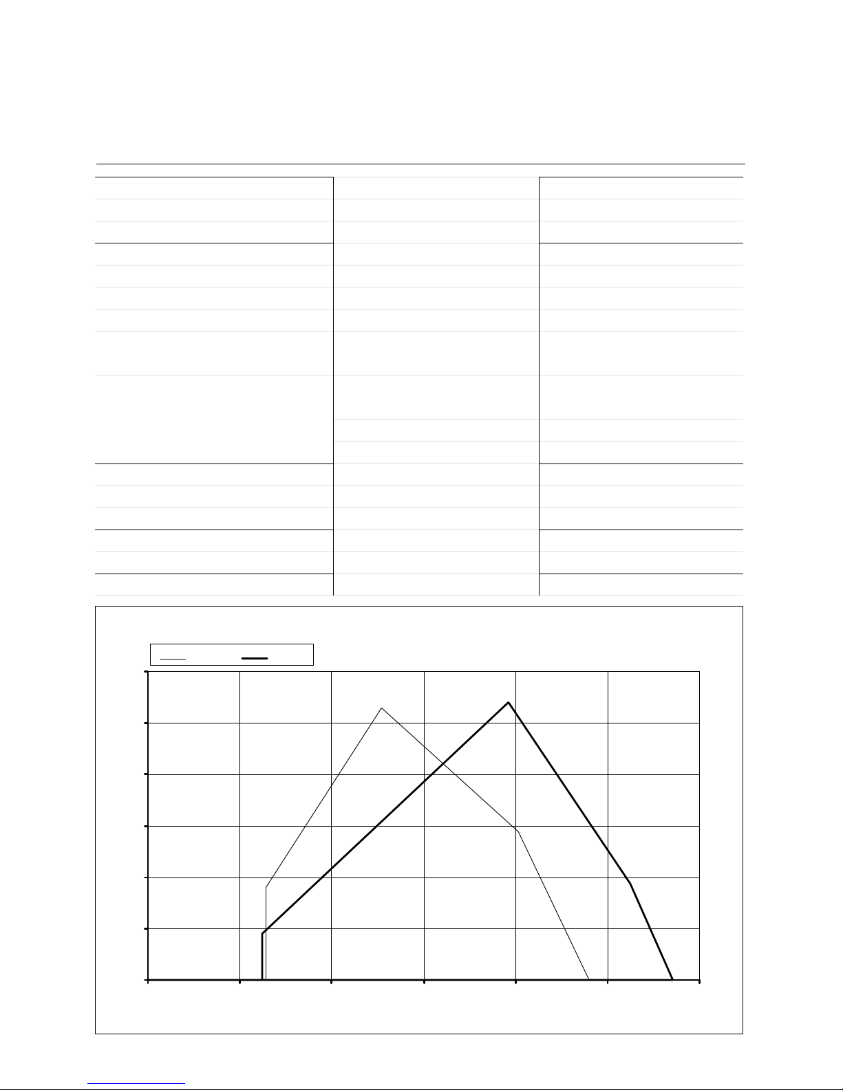
Operating range EK 7... L-E
0
5
10
15
20
25
30
0 1000 2000 3000 4000 5000 6000
7.350 L 7.450 L
Q Burner output [kW]
F
Air temperature 20°C, test values according to EN 267 (DIN 4787) at 171 m
above sea level
Pressure in
c
ombus
t
ion
c
hamb er [mb ar]
7.350 L-E
1115 - 4500 kW
94 - 380 kg/h
fully modulating
Light oil EL
BCS / LAL 2.2 / LOK 16
QRB 3 / RAR 7
400 / 690 V, 50 Hz
5,5 kW, 11,7 A, 2800 min-¹
KL-TA 4C - 2,2 kW
SMG 19065 - 1,5 kW
800 l/h / 900 l/h
30 bar
RDG 1250
Thread M14
DN 20 x 1500 / R 3/4"
SAD 15 / STM 40 / MM1004 / EA2
250 kg
≈
ZA20 140 / ZM20-14
7.450 L-E
1300 - 5300 kW
110 - 447 kg/h
fully modulating
Light oil EL
BCS / LAL 2.2 / LOK 16
QRB 3 / RAR 7
400 / 690 V, 50 Hz
7,5 kW, 15,5 A, 2800 min-¹
KL-TA 5C - 2,2 kW
SMG 1629 - 2,2 kW
1200 l/h
30 bar
RDG 1250
Thread M14
DN 20 x 1500 / R 3/4"
SAD 15 / STM 40 / MM1004 / EA2
250 kg
≈
ZA20 140 / ZM20-14
No.: 102.880.436403/05
Technical Data
EK 7... L-E
Page 7

7
Technical Data Sheet
Monoblock Oil Burner
EK 8... L-E
Technical Data
Burner output
Fuel flow rate
Operating mode
Type of fuel
Burner control box
Flame sensor
Fan motor
Pump unit
Gear output
Pressure
Nozzle rod
Nozzle
Oil hoses / External connection
Actuator
Ignition transformer
Weight
Operating range EK 8... L-E
0
5
10
15
20
25
30
0 1000 2000 3000 4000 5000 6000 7000 8000 9000
8.550 L 8.700 L
Q Burner output [kW]
F
Air temperature 20°C, test values according to EN 267 (DIN 4787) at 171 m
above sea level
Pressure in
c
ombus
t
ion
c
hamb er [mb ar]
8.550 L-E
2000 - 6049 kW
168 - 510 kg/h
fully modulating
Light oil EL
BCS / LAL 2.2 / LOK 16
QRB 3 / RAR 7
400 / 690 V, 50 Hz
11 kW, 22,5 A, 2800 min-¹
KL-TA 5C - 2,2 kW
SMG 1629 - 2,2 kW
1200 l/h
30 bar
RDG 1250
Thread M14
DN 20 x 1500 / R 3/4"
SAD 15 / STM 40 / MM1004 / EA2
320 kg
≈
ZA20 140 / ZM20-14
8.700 L-E
2000 - 7672 kW
168 - 647 kg/h
fully modulating
Light oil EL
BCS / LAL 2.2 / LOK 16
QRB 3 / RAR 7
400 / 690 V, 50 Hz
15 kW, 30 A, 2800 min-¹
KL-TA 3C - 3,0 kW
SMG 1630 - 3,0 kW
1700 l/h
30 bar
RDG 1250
Thread M14
DN 25 x 1500 / R 1"
SAD 15 / STM 40 / MM1004 / EA2
350 kg
≈
ZA20 140 / ZM20-14
No.: 102.880.437503/05
Technical Data
EK 8... L-E
Page 8
8
Technical Data Sheet
Monoblock Oil Burner
EK 9... L-E
Technical Data
Burner output
Fuel flow rate
Operating mode
Type of fuel
Burner control box
Flame sensor
Fan motor
Pump unit
Gear output
Pressure
Nozzle rod
Nozzle
Oil hoses / External connection
Actuator
Ignition transformer
Weight
Operating range EK 9... L-E
0
5
10
15
20
25
30
0 2000 4000 6000 8000 10000 12000
9.850 L 9.1000 L
Q Burner output [kW]
F
Air temperature 20°C, test values according to EN 267 (DIN 4787) at 171 m
above sea level
Pr
essure in c
ombustio
n cha
m
b
e
r [m
b
ar]
9. 850 L-E
2574 - 9596 kW
217 - 809 kg/h
fully modulating
Light oil EL
BCS / LAL 2.2 / LOK 16
QRB 3 / RAR 7
400 / 690 V, 50 Hz
18,5 kW, 35 A, 2800 min-¹
KL-T 4C
SMG 1631 - 4,0 kW
2250 l/h / 2200 l/h
30 bar
RDG 1250
Thread M14
DN 25 x 1500 / R 1"
SAD 15 / STM 40 / MM1004 / EA2
450 kg
≈
ZA20 140 / ZM20-14
9.1000 L-E
2490 - 11409 kW
210 - 962 kg/h
fully modulating
Light oil EL
BCS / LAL 2.2 / LOK 16
QRB 3 / RAR 7
400 / 690 V, 50 Hz
22 kW, 42,5 A, 2800 min-¹
KL-T 4C
SMG 1631- 4,0 kW
2250 l/h / 2200 l/h
30 bar
RDG 1250
Thread M14
DN 25 x 1500 / R 1"
SAD 15 / STM 40 / MM1004 / EA2
490 kg
≈
ZA20 140 / ZM20-14
No.: 102.880.438603/05
Technical Data
EK 9... L-E
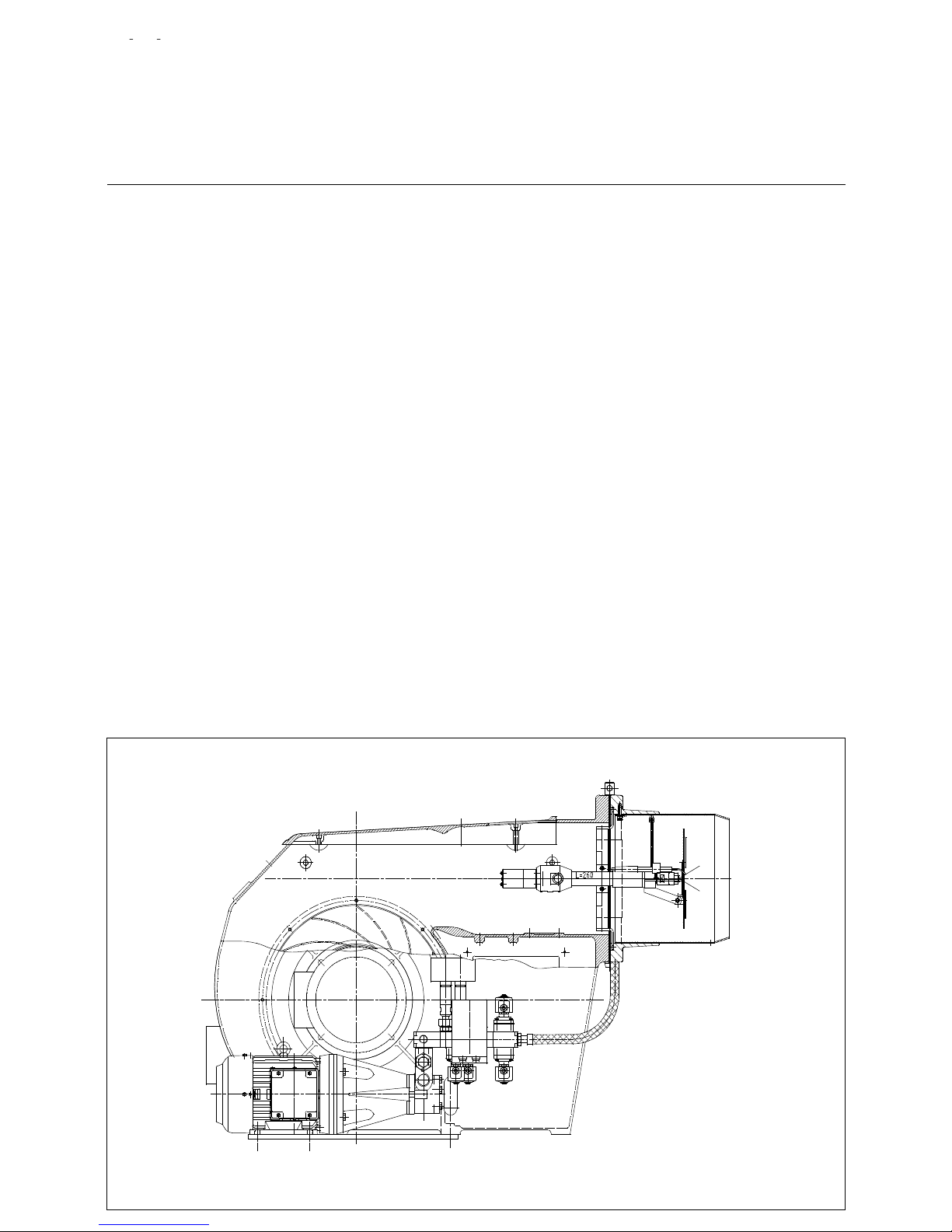
Page 9
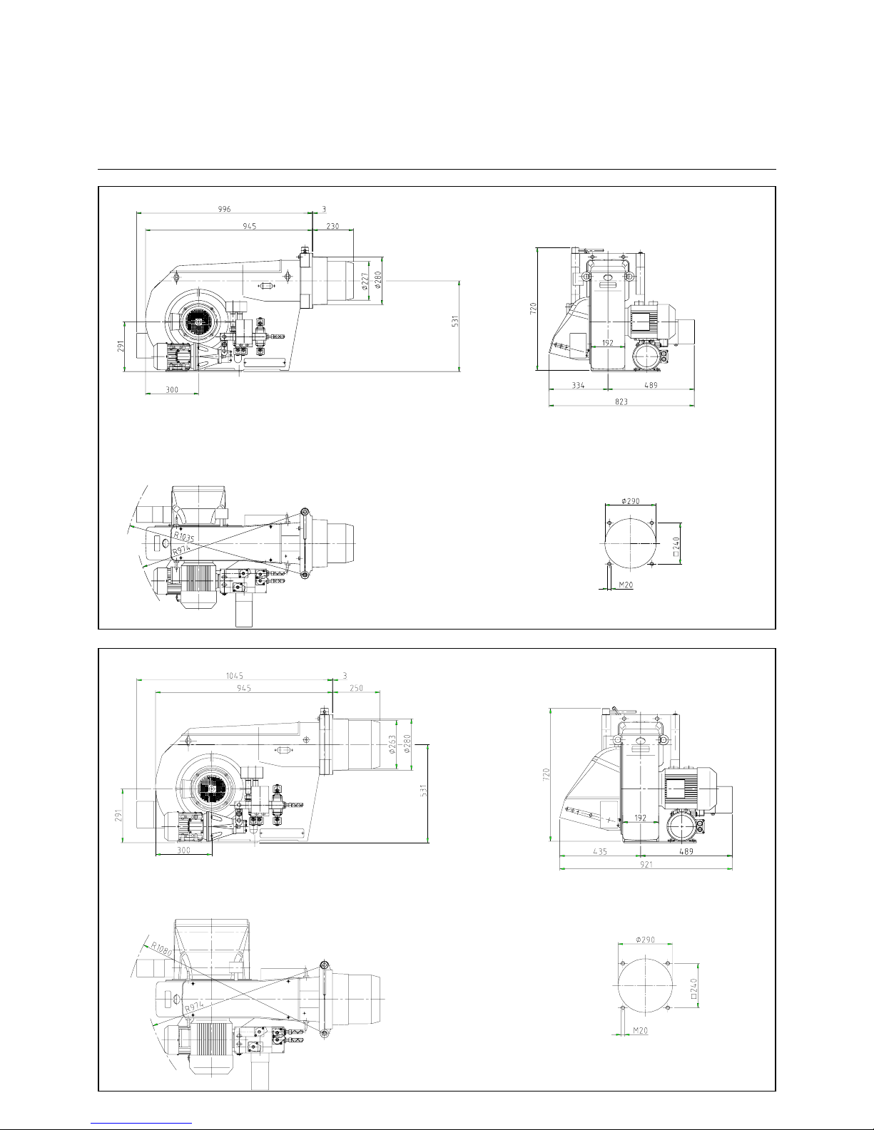
9
Overview
Dimensioned Drawings
EK 6... L-E
EK 6.170/200 L-E
Dimensions in boiler connection plate
EK 6.240/300 L-E
Dimensions in boiler connection plate
Page 10
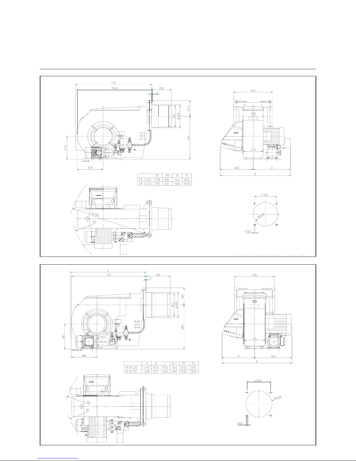
10
Overview
Dimensioned Drawings
EK 7... / 8... L-E
EK 7.350/450 L-E
Dimensions in boiler connection plate
Type
EK 8.550/700 L-E
Dimensions in boiler connecti on plate
Type
Page 11
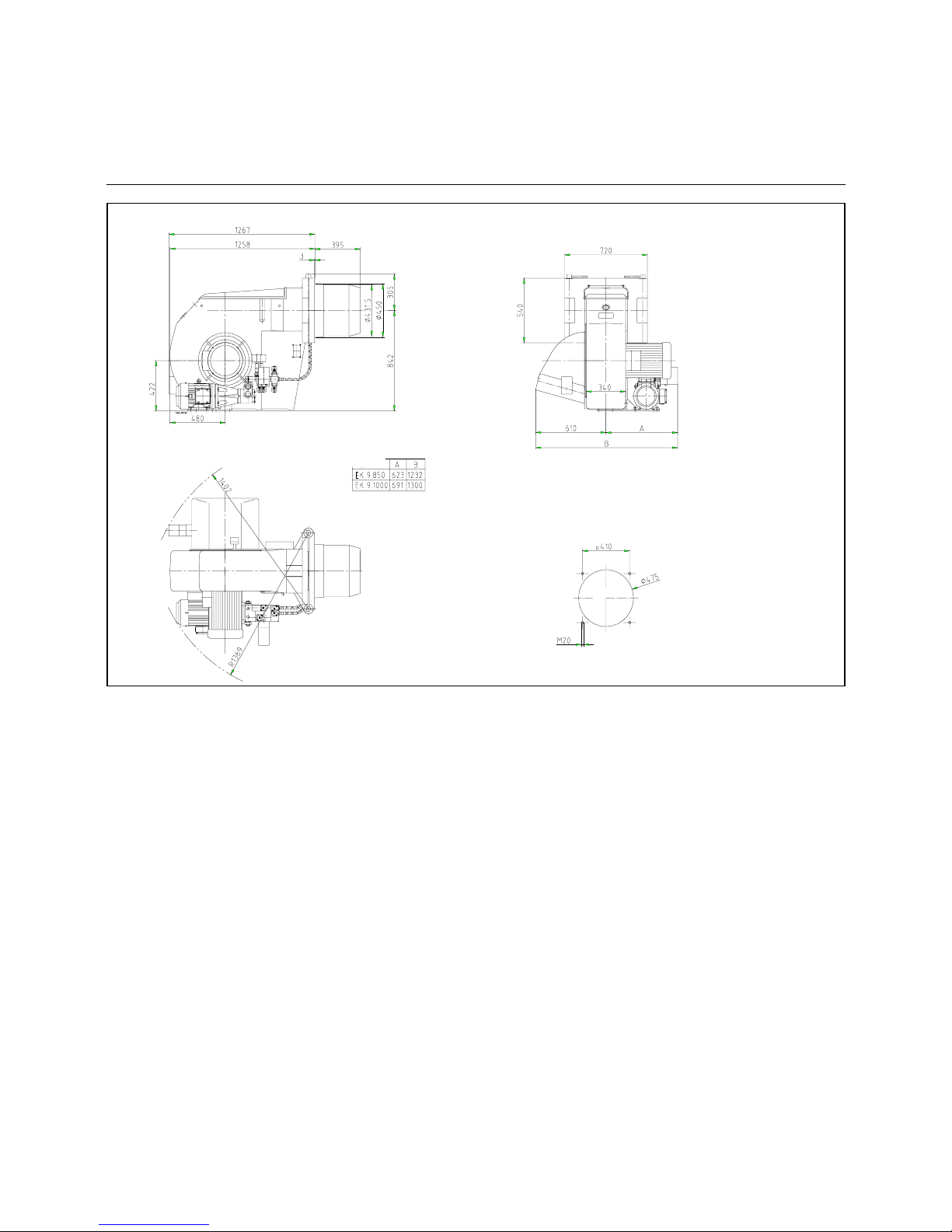
11
Overview
Dimensioned Drawings
EK 9... L-E
EK 9.850/1000 L-E
Dimensions in boiler connection plate
Type
Page 12
12
Operation
Start-up Mode
Oil Operating Mode
General Safety Functions
Start-up mode
As soon as the furnace system is required to supply heat the bur ner c ont rol c ircuit will clo se and the program be
started. After the prog ram has ru n down
the burner will start.
The air damper is closed when the
burner is out of operation.
The automatic furnace controller controls and monitors the starting function.
The electric actuator opens the closed
air damper to its full-load position so
that the burner will sweep the furnace
compartment and exhaust ports at t he
required air flow rates. Shortly after the
pre-ventilation pro cess has been star ted
the lack-of-air cut-out must change ov er
to operating position within a certain
time, i.e. the minimum air pressure setting must be reached and maintained
until the burner is turned off. At the end
of the specified pre-ventilation time the
air damper will be moved into its par tialload position. This operation will be followed by the pre- igniti on proc edure and
the oil feed start.
The solenoid valves will open and thus
allow the pressurized oil to flow to the
nozzle and to t he return line. The oil will
be atomized, mixe d with the combus tion
air and ignited.
A safety period is provided to allow the
flame to develop a proper and steady
pattern. On the terminati on of the safety
period, a flame signal must have been
received by the automatic furnace controller via the flame monitor and remain
on until the regular shut-of f. The start-up
program of the burner has now been
completed.
Oil operating mode
After the flame has developed the load
regulator will be enabled which brings
the burner into its operating position.
The load regulator will now control the
burner automatically between its partialload and full-load stages.
Depending on the heat rate required the
servomotor will via the controller be
given an "open" or "close" signal and
thus increase or decre ase the oil and air
flow rates.
This compound c ontrol conc ept will v ary
the position of the oil control valve and
air damper and thus adjust the oil flow
rate in relation to the air flow rate.
The stepless control will allow the burner to be operated at any desired stage
between its partial-load and full-load
positions. The burner will be turned off
from its partial-load position. The air
damper will be closed when the burner
is out of operation and will thus prevent
cold air flowing through the burner
chamber, heat exchanger and chimney.
The interior cooling losses will be greatly minimized.
General safety functions
In case a flame does not develop when
starting the burner (fuel release) the
burner will shut off at the end of the
safety period (shut-off on trouble). A
shut-off on trouble will also occur in the
case of flame f ailure during oper ation,
air flow failure during the pre - ven til ati on
phase and pressure failure during the
whole period of burner operation. Any
failure of the flame signal at the end of
the safety period and a flame signal
during the pre-ventilation phase (external light control) will result in a shut-off
on trouble with the automatic furnace
controller being locked. The trouble is
indicated by the trouble signal lamp
lighting up. The automatic furnace controller can be unlocked immediately
after a shut-off on trouble by pressing
the unlocking key. The program unit will
return to its starting position and proceed with the restart of the burner.
A voltage failure will result in a regular
shut-off of the burner. Upon voltage
recovery there may be an automatic
restart unless another interlock is provi-
ded, e.g. by the safety system. In any
case of trouble the fu el oil suppl y wi ll be
shut off right away. The program unit
will stop at the same time causing also
the trouble location indicator to stop.
The symbols will indicate the kind of
trouble.
When using the burner control system
type BCS all operational and fault messages may be indicated in plain text on
an optionally available operating and
display module.
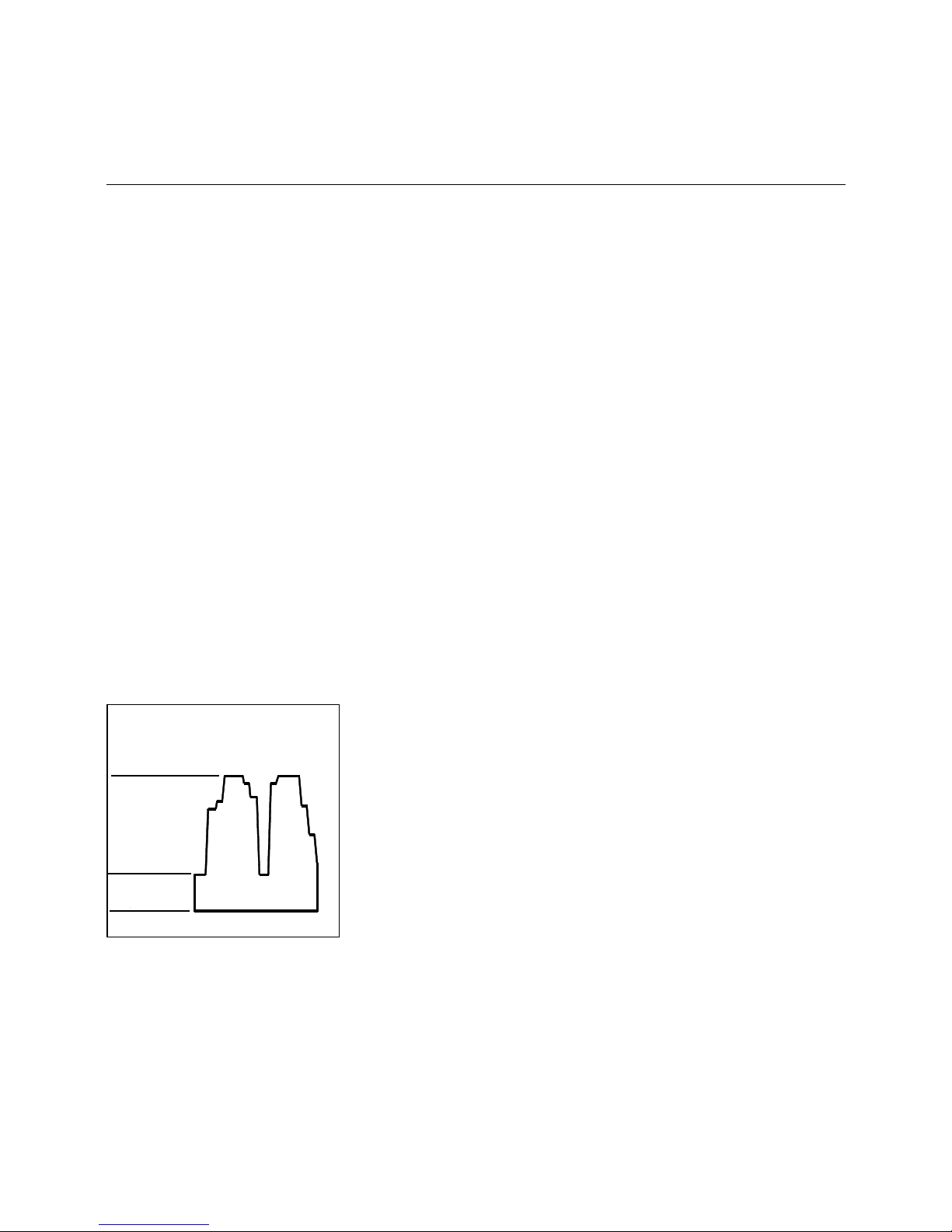
Zündung/Ventile
Pumpe
Teillast
EIN
Freigabe
Leistungsregulierung
Betriebsstellung
Vollast
AUS
Oil control
steepless
Full load
Operating position
Load regulator
Release
Partial load
Ignition/valves
Pump
ON OFF
Page 13
13
Operation
Fuel-air Compound Control
Hydraulic Diagram
Fuel-air compound control
This compound pneumatic control
system with precision-adjustment capability has been designed to allow the
fuel and air flow rates to be steadily
varied in sliding mode for an adjust ment
of the fuel-air ratio over the whole control range.
In the two-stage sliding control concept
the partial-load and full-load positions
are within the control range. Depending
on the heat demand these two load
points will be selected in sliding mode.
A larger fuel feed will not be suddenly
turned on or off. In the stepless control
mode the load will be controlled at any
point within the control rang e dependin g
on the heat demand. The two-stage sliding and the stepless control concepts
are different only in the contr ol systems
used with the burners. The same mode
of operation is used for both versions.
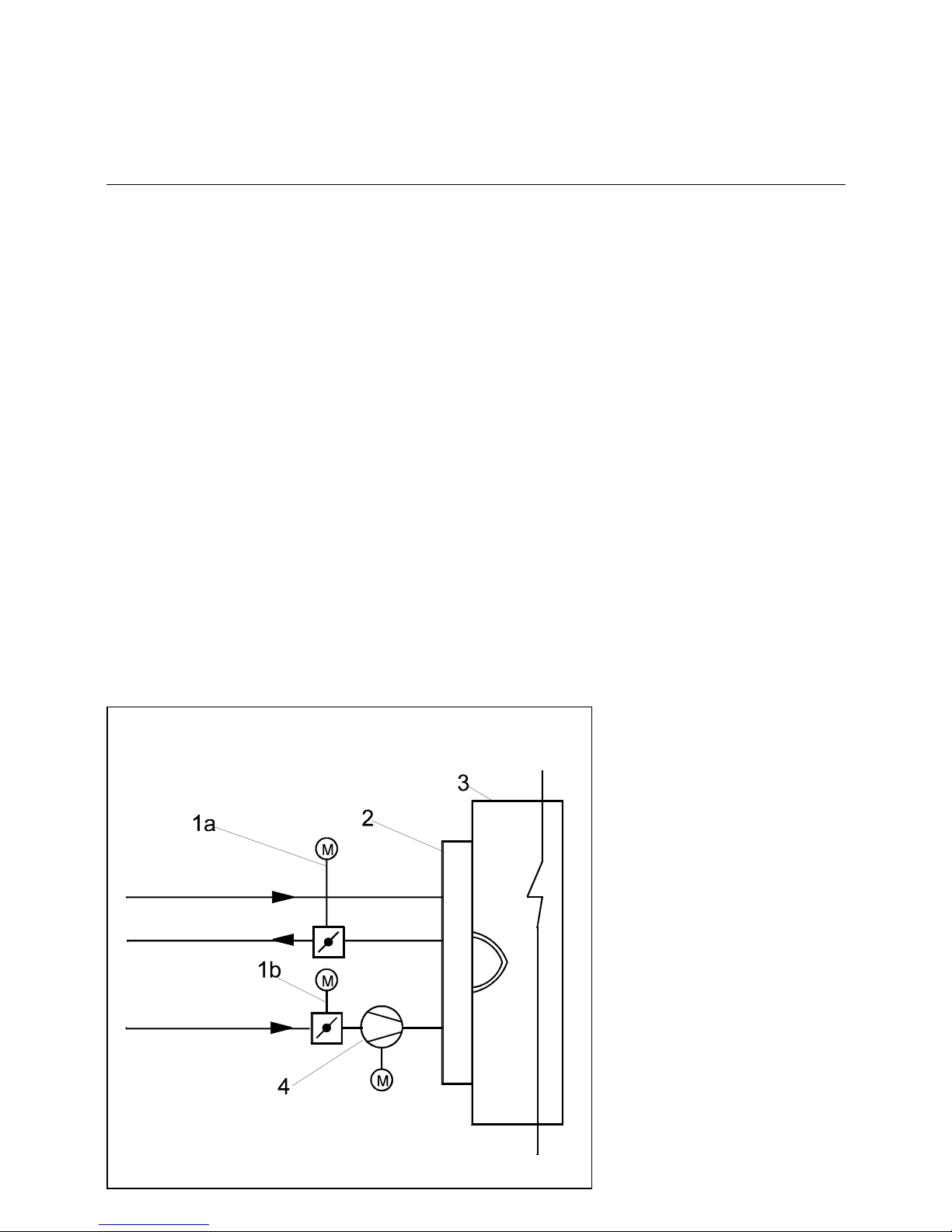
Electronic compound control:
The air box includes an actuator for
operating the air dam per . Th e oil co ntrol
valve incorporates an actuator for adjusting the return oil flow rate and thus th e
output of the burner.
The actuators for the air and fuel flow
control will be operated depending on
output by the electronic compound control which will move them into the programmed positions.
Electronic compound control
Oil feed
Oil return
Air
1a Oil control valve with actuator
1b Air dampers with actuators
2Burner
3Boiler
4 Combustion air fan
Page 14

14
Operation
Hydraulic Diagram L-E / GL-E
Burner EK 6 - EK 9
120 Air damper
175 Filter
176 Pump
178 Feed solenoid valve
180 Nozzle rod
181 Return solenoid valve
184 Output control valve
187a Pressure re gulating valve
(integrated in pump)
311 Return oil pressure switch
312 Feed oil pressure switch
349 Actuator
In case of TRD 604/72 hr control
items (pos. 311, 312) need to be
tested according to „special construction design“ or must be installed twice.
312
RL
181
175
187 a
VL
176
311
178
178
M M
120
184
349
349
180
181
Hydraulic diagram -DIN / EN
RL
175
187 a
VL
176
311
312
178
178
181
180
181
M
184
120
M
349349
Hydraulic diagram -TRD 604/72 h
Page 15

15
Operation
Hydraulic Valves and Instruments Group
The hydraulic valves and instruments
group is an integrated concept that
combines several functions of the
hydraulic systems of burners. Its modular construction makes it possible to
meet a wide range of requirements and
conditions of installation. The pump
adapter module (1) allows the hydraulic
valves and instruments group to be
mounted directly to oil burner pumps of
any size. It is fastened to the pump by
means of hollow bolts which are provi-
ded with ¼" screw plugs (4) for venting
the pump when taken into operation.
The basic group module (2) is moun-
ted to the pump adapter with the two
modules being sealed against each
other by O-rings in the supply and
return pipes. Depending on the level of
equipment of the hydraulic system, oil
pressure switches and pr essure gauges
may be installed in the supply and
return pipes of the basic module. The
solenoid valve in the supply pipe is of
servo-assisted type while the return
valve is directly controlled. The solenoids of the two valves are electrically
connected i n series which will prevent
one of the valves being opened alon e if
any of the so lenoids is defective. For
the replacement of the solenoid valves
during maintenance work it should be
ensured that the right valve type is
installed in the correct direction of
mounting. For mounting the solenoid
valve in the supply pipe (type 321 H
2520) it must be ensured that the direction of flow shown be a stamped arrow
on the valve flange is the same as the
direction of flow of the oil (from the
pump to the nozzle rod). The solenoid
valve in the return pipe (type 121 G
2520) is marked with a stamped arrow
opposite to the direction of the oil flow
from the nozzle rod back to the pump.
The volume flow control valve installed
in the return pipe consists of a bush
pressed into the hydraulic valves and
instruments group and locked against
torsion and a control shaft. As the control shaft is turned, the contoured configuration of the bush and shaft will
change the open cross section for the
oil flowing back and thus vary the oil
return flow rate. Control shafts with different control contour parameters are
available for adjustment to various oil
nozzle sizes. This c onc ept ensures that
an excellent control characteristic and a
wide control range can be c overe d for a
great variety of applicatio ns. The co ntrol
contour parameter is affixed to the control shaft by means of an electric marker. The current position of the control
shaft is indicated by the position display.
From the "min." mark (low load of burner) the control shaft will turn clockwise
to the "max." mark (full load of burner).
If the control shaft has been removed
during maint enance work care shou ld
be taken when reinstalling it to ensure
the right mounting position o f the co ntrol
contour by observing the centre punch
mark on the shaft end face. In the low
load position (min.) the centre punch
mark will in any case point up (12
o'clock position - see figure).
If the hydraulic valves and instr uments
group is used in conju nctio n with nozzle
rods not approved as safety shut-off
valve according to EN 264, an exten-
sion module (3) is available which
incorporates an additional solenoid
valve each in the supply and return
pipes. The ex tension module is attached directly to the basic module. The
modules are sealed against each other
by O-rings.
Metal hoses are used for connection
between the hydraulic valves and
instruments group and the nozzle rod.
The hose lines must be protected
against exterior mechanical damage.
The hoses must be positioned and
mounted in accordance with the applicable technical standards. For the
installation care must be taken not to
introduce torsional or buckling stresses
neither by the mounting procedure nor
by movements at a later stage. Specified bending radii of the h ose s m us t not
be changed.
Pumpadapter
4
Basic module
Extension module
Control shaft installation
Complete hydraulic valves and
1
2
3
instruments group
Page 16

16
Start-up
Burner Head Settings
EK 6... L-R/E
EK 6.170 L-R/E EK 6.200 L-R/E
EK 6.240 L-R/E EK 6.300 L-R/E
Page 17

17
Start-up
Burner Head Settings
EK 7... / 8... L-R/E
EK 7.350 L-R/E EK 7.450 L-R/E
EK 8.550 L-R/EEK 8.550 L-R/E EK 8.700 L-R/E
Page 18

18
Start-up
Burner Head Settings
EK 9... L-R/E
EK 9.850 L-R/E EK 9.1000 L-R/E
Page 19

19
Installation
Mounting to Boiler
Electrical Connection
Presetting
Burner mounting
For mounting the burner to the boiler
make sure the connection plate has
been prepared according to the dimensions given in the technical datas heets.
• Install the stud bol ts in the connection
plate.
• Put the insulating backing and burner
in place and fasten by bolts.
Check before burner installation
1. Select the nozzle according to
boiler output and combustion
chamber geometry.
2. Set the mixing and ignition unit
according to the boiler output.
For the standard factory setting
refer to the burner head settings.
3. Set the ignition electrodes on the
nozzle.
4. Check the burner tub e ins t a lla tion
depth according to the data specified by the burner and boiler
manufacturers.
Electrical connection
The electrical connection work comprising all the installation materials, terminals and eart h connections must be
carried out in accordance with the applicable regulations. For the electrical
installation of the burner care must be
taken to observe the circuit diagram
made out for the furnace system.
The electrical connection of the burner
and gas valves a nd instrume nts shal l be
entrusted to authorized specialists only.
NOTE: For the installation of the connection cables care must be taken to
provide cable loops of sufficient length
to allow for the swing-out of the boiler
door and burner .
Make sure after the completion of the
electrical connection work to check the
wiring of the electrical system of the
burner. This should include a check of
the direction of rotation of the burner
motor (fan).
Boiler inspection glass cooling
For cooling and cleaning the boiler
inspection glass a cooling line (e.g.
hose) may be installed from the burner
to the inspection glass. The burner is
provided with a connection socket for
this purpose.
approx. 6 mm
approx. 15 mm
approx. 10 mm
Page 20

20
Installation
Boiler lining for Burner L-R/E
Boiler lining
Example of boiler lining for three-pass
boilers:
The space between the flame tube of
the burner φD and the boiler lining φ D1
must be packed wi th heat-resistant
material, e.g. Cerafelt.
This space is not allowed to be lined
with brickwork.
Boiler lining
Example of boiler lining for reve rse-flo w
boilers:
T1 according to the boiler or burner
manufacturer’s instructions.
The space between the flame tube of
the burner φD and the boiler lining φ D1
must be packed wi th heat-resistant
material, e.g. Cerafelt.
This space is not allowed to be lined
with brickwork.
Burner type Dimension A Dimension T φD φD1
Standard 100 ext. 200 ext. (Standard)
EK 6.170 230 330 430 230 227 290
EK 6.200 230 330 430 230 227 290
EK 6.240 250 350 450 250 263 290
EK 6.300 250 350 450 250 263 290
EK 7.350 282 382 482 282 306 360
EK 7.450 282 382 482 282 325 360
EK 8.550 362 462 562 362 346 400
EK 8.700 362 462 562 362 369 400
EK 9.850 395 495 595 395 431 475
EK 9.1000 395 495 595 395 431 475
Boiler lining
Page 21

21
Installation
Oil Connection
Oil Pressure Control (Feed)
Oil connection
Hoses are used for connection to the oil
lines and stop valves. The hoses must
be installed according to the applicable
standards (relieved of tensile load, free
of distortion) to avoid kinking and
exclude the danger of breakage. Take
care when mounting the oil lines to
bring their ends as close to the burners
as possible and to arrange them in a
way that the boiler door and the burner
can be swung out without any obstruc-
tion.
Refer to the techni cal docum entation f or
the line dimensions for the feed and
return lines from the stop valves to the
tank.
Oil filter
A filter must be inst alled upstream of the
pump to protect the oil pressure pump
and the hydraulic system.
Installation options
• Two-line installation
(separate feed and retu rn lines withou t
delivery pump)
• Ring line system
(with delivery pump and gas-air separator)
Instrument mounting
Prior to adjusting the burner make sure
to mount the test pressure gauges for
measuring the feed pressure ( Item 2)
and return pressure (Item 1).
A vacuum gauge and pressure gauge
are mounted to the oil pump for measuring the oil pressure.
NOTE: After the burner has been tak en
into operation the gauges must be
removed again and the connections
sealed with suitable means. If the gauges are mounted to remain on the burner they should be fitted with stop
valves.
Oil pressure control (feed)
The feed pressure is controlled by
means of the pressure regulator installed in the pump and should be set at
approx. 25 to 30 bar depending on burner output and nozzle make. The pressure regulator is operated by turning its
screw. Make sure to fill the pump with
oil prior to taking into operation.
Pump bleeding
Open the feed and return stop valves
and ensure the ring line (if any) is in
operation. Reduce the oil pressure at
the pressure regulating valve. Turn on
the pump by pressing the contactor.
Check the pump for proper direction of
rotation. Check for proper oil delivery
and absence of leaks in the hy draulic oil
system. For bleeding the pump open
the pressure gauge connection, for
example. When taking the burner into
operation proceed by gradually increasing the pressure to operating level (2530 bar).
Checking the pressure (oil suction
pressure)
The maximum permissible vac uu m is
0.2 bar . At higher vac uum levels t he fuel
oil will tend to gas evolution which may
lead to operating tro uble. In the ring line
mode of operation the pump oil pressure is not allowed to exceed 5 bar.
Range of application of oil hoses
Burner type DN Lenght
[mm]
Connection
on both ends
Minimum bending
radius [mm]
EK 6.170/200 16 1500 R 1/2" 230
EK 6.240 20 1500 R 1/2" 230
EK 6.300 20 1500 R 1/2" 240
EK 7 20 1500 R 3/4" 240
EK 8.550 20 1500 R 3/4" 240
EK 8.700 25 1500 R 1" 250
EK 9 25 1500 R 1" 250
1
2
Page 22

22
Start-up
Return Nozzle Rod Type RDN
Burner Type EK 6
'HVFULSWLRQ
7KHUHWXUQQR]]OHURGW\SH5'1LVVXLWD
EOHIRURSHUDWLRQZLWKWKHUHWXUQQR]]OH
W\SH)OXLGLFV:or Bergonzo CBM
type B with 7/8 in. connection thread
7KLVQR]]OHVLQFRUSRUDWHVDVSULQJ
ORDGHGVKXWRIIV\VWHPZLWKDFXWRII
QHHGOHGLUHFWO\FORVLQJWKHQR]]OHKROH
7KHFXWRIIQHHGOHLVDFWXDWHGE\WKH
FRQWUROQHHGOHWKDWLVFRQQHFWHGZLWK
WKHK\GUDXOLFSLVWRQV\VWHPRIWKH
QR]]OHURG
7KHVWURNHRIWKHFRQWUROQHHGOHPXVW
EHGLPHQVLRQHGVRWKDWWKHQR]]OHZLWK
WKHPD[LPXPSRVVLEOHQHHGOHVWURNHLQ
RSHQHGQHHGOHSRVLWLRQKDVVWLOOVRPH
FOHDUDQFHEHWZHHQVSULQJGLVNDQGFRQ
WUROQHHGOHKHDG,ILQFDVHRIORZSXPS
SUHVVXUHEDUWKHFRQWUROQHHGOHLV
QRWSUHVVHGLQWRLWVIXOO\RSHQHGSRVLWLRQ
WKLVPD\FDXVHWKHWKURXJKSXWUDWHWR
YDU\EHFDXVHWKHQHHGOHSRVLWLRQKDV
DQLPSDFWRQWKHRLOUHWXUQIORZ
5HW
XUQQR]]OHURGW\SH
5'1
6WURNHDGMXVWHUFRQWUROQHHGOH
+\GUDXOLFSLVWRQV\VWHP
2LOUHWXUQFRQQHFWLRQ
2LOVXSSO\FRQQHFWLRQ
5HWXUQQR]]OHW\SH)OXLGLFV:
127(7KHVWURNHDGMXVWHULVIDF
WRU\VHWDQGPXVWQRWEHFKDQJHG
GXULQJWKHRSHUDWLRQRIWKHV\VWHP
7KHVWURNH+LVPPDQGPD\EHVHW
ZLWKWKHUHTXLUHGGHJUHHRIDFFXUDF\LQ
DVXLWDEOHK\GUDXOLFWHVWULJRQO\
)XQFWLRQLQJRIQR]]OHW\SH:RU
&%0%
2SHQLQJWKHQR]]OH
7KHVXSSO\RLOSUHVVXUHFDXVHVWKH
SLVWRQLQWKHK\GUDXOLFV\VWHPDQGZLWK
LWWKHFRQWUROQHHGOHWREHUHWUDFWHG
7KHVSULQJLQWKHQR]]OHRSHQVWKH
FXWRIIQHHGOH
&ORVLQJWKHQR]]OH
7KHEXUQHUVWRSVDQGWKHK\GUDXOLF
SLVWRQV\VWHPLVGHSUHVVXUL]HG
7KHFRQWUROQHHGOHEULQJVVSULQJ
IRUFHWREHDURQWKHFXWRIIQHHGOHRIWKH
QR]]OHFDXVLQJLWWRPRYHLQWRLWVFORVHG
SRVLWLRQ
2SHQLQJSUHVVXUH EDUIXOO\RSHQ
DWEDU
&ORVLQJSUHVVXUH EDU
&RQWUROQHHGOH
2SHQLQJVSULQJRIQR]]OH
&XWRIIQHHGOH
1R]]OHFORVHG
1R]]OHRSHQ
Page 23

23
Start-up
Nozzle Selection, Type W2-50°
Return nozzle
The nozzle type Fluidics W is a return
nozzle with i ntegrated spring-loaded
cut-off needle. The throughput rate is
controlled by varying the return pressure while keeping the supply pressure
at a constant level.
Prior to burner start, check the nozzle
size against the required out put. It might
be necessary to replace the nozzle (see
nozzle selection diagram).
Nozzle selection diagram
The diagram shows the maximum
throughput rates of th e return no zzles in
dependence of the supply oil pressure.
Supply oil pressure: min. 20 bar
max. 30 bar
Nominal supply oil
pressure: 28 bar
Return oil p ressure: min. 8 bar
Example
Required oil throughput
rate 238 kg/h
Nozzle size accord ing
to diagram W2-225
Supply pressure according
to diagram 28 bar
W 100
W 115
W 130
W 145
W 160
W 180
W 200
W 225
W 250
W 275
W 300
0
50
100
150
200
250
300
350
20 21 2 2 23 24 25 26 27 28 29 30
Vorlauf Öldruck [bar]
Öldurchsatz [kg/h]
Throughput rates shall apply to closed return
Density: 840 kg/m
3
Viscosity: 5 mm2/s
Nozzle type: W2-50°
Oil throughput rate [kg/h]
Supply oil pressure [bar]
Page 24

24
Start-up
Return Nozzle Rod RDG 1250
Function description
The return nozzle rod RDG 1250 is for
return nozzle without integrated needle
valve and comes with M14 screw connection (for example Sonic DZ 100 0,
CBM M14).The locking mechanism
consisted of a slider with se al ring (Pos.
2 and 6) in the forward flow section and
a needle valve (Pos. 5) in the return
flow section, using the sliding rod control by a hydraulic con trol- piston syst em
located at the back of the nozzle rod.
The opening pressure of RDG 1250 is
about 3 bar in forward flow section or 13
to 20 bar in return flow section. When
the solenoid valves are open, the pressure from the oil would retract the control-piston via the pressure channel
(Pos. 7) and then push open the slider .
Both the control-piston and sliding rod
with needle valve wou ld remain open as
long as there is an exi sting oil pres sure.
The same oil pressure would keep the
slider open. Under normal circumstances, both lock in g mec han isms
would open at the same time. The oil in
the forward flow section would exit
through the nozzle head to be mixed
with the air for combustion. The remaining oil would be red ire cte d t hrou gh th e
return holes of the nozzle back into the
return flow section of the nozzle rod
assembly. When it is not in operation,
the swirl plate in the nozzle head blocks
the return flow.The return oil flow rate
can be adjusted accordingly using a
pressure control valve If the pump pressure is too low (<20 bar), thereby preventing the control needle from opening
all the way, variations in throughput are
to be expected as the needle position
will affect the return oil fl ow.
Control-piston openi ng distanc e H is set
in the factory at 9mm. Any adjustment
at installation site is not necessary.
1
5
3
6
4
7
2
+
The Control piston
opens at ca. 13 bar;
Fully open at 20 bar.
Close at 10 bar.
1 Return Nozzle
2 Slider
3 Spring (Forward)
4 Sliding rod
5 Needle valve
6 Seal ring (Forward)
7 Pressure channel
Distance H = 9 mm
Forward
Valve
Page 25

25
Start up
Nozzle selection „Sonic“
160 kg/h
240 kg/h
300 kg/h
350 kg/h
400 kg/h
450 kg/h
500 kg/h
550 kg/h
650 kg/h
700 kg/h
750 kg/h
800 kg/h
850 kg/h
900 kg/h
950 kg/h
1000 kg/h
Diagram - of Sonic-Spray return nozzle DZ 1000-60°
with controlled return
Light fuel Oil
Feed pressure 28bar
Return nozzles of the type SonicSpray are availa bl e in different ratin gs
with an angle of spray of 45°, 60° or
80°.
The 45° nozzles are preferably used
for reversed-flow furnaces while the
60° and 80° nozzles are operated in
three-pass boilers and swirl-type
mixing installations, respectively.
Quantity Oil Nozzle [kg/h]
Return Pressure at the Hydraulicblock [bar]
Page 26

26
Start-up
Checking Procedure
Check the following prior to the
initial operation of the boiler system:
• Take care to observe the operating
instructions supplied by the boiler
manufacturer. The boiler must be
mounted ready for operation.
• Ensure that the heating system is fi lled
with water to capacity.
• Check the complete system for correct
electrical wiring.
• Check the burner motor for correct
direction of rotation.
• Check for the proper setting of the
temperature and pressure controllers,
limiters, safety switches and electrical
limit switches.
• Bleed the fuel-carrying lines (make
sure they are free of air).
• Check tank, lines and oil pump are filled with oil and correct oil nozzle is fitted.
• Check the oil hydraulic system is free
of leaks.
• Check the exhaust gas ports are opened and adequate fresh air intake is
ensured.
• With burner in starting position check
that air damper is in „CLOSED“ position.
• Check that automatic furnace controller is unlocked and in its original position.
Prior to the initial oil feed start make
a functional test of the burner
program flow:
Oil system:
• Open all shut-off valves of the oil supply system.
• The oil solenoid valve in the feed line
disconnect on the terminal strip (see
Circuit Diagram).
• Start burner and check program flow
for correct start-up sequence.
1. Fan starts.
2. Pre-ventilating damper.
3. Air pressure check.
4. Partial-load air damper.
5. Ignition.
6. Valves open (disconnec ted valve
remains closed) .
7. Shut-off upon trouble after expiry
of safety period (see automatic
furnace controller).
• Reconnect the valve.
• Unlock the automatic furnace controller.
Oil start-up
Open all shut-off valves of oil su pply
system.
• Set fuel selector switch to its „Oil“
position.
• Fill pump with oil.
• Mount pressure gauge in the feed line
and return line.
• Mount the pressure gauge for
checking the pump suction pressure.
Bleeding
Shortly start the burner and check for
proper direction of rota tion. Bleed the oil
line and oil pump.
CAUTION: The hydraulic system has
been filled with test oil by the manufacturer. This may cause ignition trouble
when initially operating the system. To
protect the pump, the oil pressure controller is factory-set at zero pressure.
When starting the burner take care to
increase the oil pressure slowly to the
operating level.
Page 27

27
Adjusting Instructions
Elektronic Burner Control with
Electronic Compound Controller
BCS
Refer to the documentation supplied
with the electronic compound control
system for the pre-operational work on
the burner, the checking requirements
(e.g. actuators, limit switches, potentiometers etc.) and the instructions for the
initial operation of the electronic compound control system.
Etamatic
Page 28

28
Adjusting Instructions
Start-up of Burner Control System Type BCS 300
Flame Detecting System Type FLW 05
Description
The electronic burner control system
type BCS 300 is a programmable automatic firing controller of modular construction with integrated electronic
compound controller. It is designed for
the control and automatic control of oil,
gas and dual-fuel burners of medium to
larger outputs.
The automatic firing controller may be
used for intermittent or continuous
mode of operation and for furnace
systems built according to TRD.
The controller consists of the following
units that communicate via a safety-oriented bus system:
- burner controller module type
BCS 300 (attached to burner)
- flame detector module type BCSFLW 05 (attached to burner)
- fuel and air servomotors
- operating and display unit type
BAM (not required for opera tion of
furnace system)
The system also incorporates a PID
firing rate controller with standard or
servo-control parameterization capability and a valve leak tester.
Technical data:
Operating voltage: 230 V a.c.
Frequency: 50-60 Hz
Power input:
BCS incl. BAM:<15 VA
FLW 05: <1.5 VA
Back-up fuse: max. 10 AF
Equipment fuse: 6.3 A slow-blow
0.1 A slow-blow
Permissible ambient temperature:
in operation: 0-60 °C
during storage: -20-70 °C
Starting the burner control system
NOTE: The burner control system is
allowed to be started by duly qualified
specialists only. The personnel operating the system should strictly observe
the applicable instructions for start-up.
Before proceeding with the programming of the system make a check
of its wiring (especially for compliance
with the relevant DIN-VDE standards
and the regulations of the local power
supply company).
The parameterization of the automatic
firing controller programs, the valve leak
test and the firing rate adjustment will
be handled from the operating and display module.
NOTE: For selecting the automatic controller programs and adjusti ng the preventilation times care should be taken to
observe the applicable standards.
The fixed safety time settings are not
allowed to be ex ten ded by external s witching operations.
The fuel-air compound curves may be
programmed by means of the operat ing
and control module or a laptop computer.
If the compound controller is adjusted
by means of the operating and display
module it will only be possible to correct
the curve point settings.
A completely new curve and the definition of new curve points can be achieved with the aid of a laptop computer
only.
After the automatic controller programs
have been set it will be possible to
check the inputs and outputs of the burner control system for proper
functioning via the operating and display module.
NOTE: For the tests, all manual fuel
shut-off valves must be kept in closed
position in any case.
The compound modules are provided
with a basic curve when delivered ex
works. This may be changed by means
of the operating and control module to
adjust it to the local conditions. For this
purpose, it is possible to correct the
damper positions for the 10 index points
in the range from 10, 20, 30, etc . to 100.
Flame detecting system
The flame detector m odule type FL W 05
is used in conjunction with the burner
control system.
The following flame sensors may be
connected to the flame detector
module:
-QRA 2
- QRA 53/55
- RAR 7/8
- ionization electrode
- any flame detector with contact
output
The sensor to be used will be selected
by appropriate programming i n the burner control system. The type of sensor
used will depend on the burner operating mode (continuous or intermittent).
The flame boosters integrated in the
flame detector will be checked for proper operation at an interval of 90
seconds in continuous mode.
Flame detectors with conta c t output
must if run in c onti nu ous m od e b e intrinsically safe because only the parts of
the BCS flame detect or a r e ch ec ked fo r
safe operation.
The intensity of the flame signals (UV
sensor, light sensor, ionization electrode) is evaluated in the burner control
system and indicated on the operating
and display module.
This allows an exact orientation of the
flame sensors.
It is not possible to measure the flame
intensity by means of instruments.
The flame sensors must be ch ecked for
accumulation of dirt at re gul ar intervals.
Take care that the sensor window is
kept free of dust all the time.
The flame intensity display may be used
as an indicator for the dirt ac cu mul ati on
load.
If the situation cannot be remedied by
cleaning it will be necessary to replace
the flame sensor.
Page 29

29
Adjusting Instructions
Start-up of Burner Control System Type
BCS 300
Servomotor Type SAD 15.0
The electronic compound control
system type BCS makes use of digitally
activated servomotors type SAD 15.0.
These consist of a stepping motor with
electronic trigger and power pack.
A driver with digital feedback via encoder disk is provided for monitoring the
function and direction of rotation.
Take care to observe the instruction for
operation for the burner control system
type BCS 300.
Dimensions:
Connection:
P1 : N, L, PE
P2, P3: 1 - EA SA
2 - EB SB
3 - OK WD
4 - GND
5 - AA MA
6 - AB MB
NOTE: Check the zero position of the
servomotors prior to start-up.
Technical documentation:
BCS 300, Dungs
Technical data:
Maximum torque 15 Nm
Gear reduction 745:1
Positioning times (at 200 Hz) 22.3s/90°
Positioning accuracy <±0.3°
Direction of rotation from zero mark to 90°counterclockwise (looking on drive
shaft)
Angular re solution stepping mo tor 0.02°
rotation monitoring 1°
Unidirectional positioning by external load
initial stress at 0.6 Nm
Supply voltage 230 V a.c. +10/-15%, 50 Hz
Current decrease 20 ms ±30% (after last step)
Protection classification IP 54
Shaft, flanged with cylindrical pin 12 dia.
h8
Ambient temperature in operation -20 to +60 °C
Cable gland with PG 11
conduit thread
and earthing
Through hole for M6 thread
P1
N L PE
P3 P2 zu
Page 30

30
Adjusting Instructions
Electrical Actuator STM 40
The actuator STM 40 is us ed i n co nne ction with the electronic burner control
systems of the firm „Lamtec“.
Technical data:
Voltage: 230V AC
Frequency: 50 Hz
Angle of rotation: 90°
Running time: 40 sec. for 90°
Torque: 15 Nm
Static holding
moment: 8 Nm
Dimensiones
(B x H x T): (93 mm x 144 mm x 149 mm)
Potentiometer
(integrated): 5 kΩ
5 k
Ω
Page 31

31
Start-up
Starting the BCS, Etamatic, VMS/FMS Electronic
Compound Controller
Starting the electronic compound
controller
For starting the electronic ratio controller make sure to proceed as described
in the operating instructions.
NOTE:
Only duly qualified personnel must be
employed for starting the controller.
For the initial operation make a check
that the controller settings are in line
with the furnace system requirements.
The configuration of the compound controller is shown on the sticker attached
to the housing side wall.
Functional test without burner start
After the electronic compound co ntroller
has been connected electrically proceed with adjusting the potentiometers
of the actuators. Start the fan for
checking the feedback of the fan speed
(press the fan contactor).
As soon as the potentiometer feedback
data have been properly set proceed
with programming the compound controller. An exact description of the programming procedure can be found in
the operation manual supplied with the
compound controller.
NOTE:
The start-up manual of the compound
controller contains information on
trouble signals, detailed instructions for
start-up and for programming the controller.
Page 32

32
Adjusting Instructions
Oil Pressure Switch
Air Pressure Switch
Oil pressure switch
Oil pressure switches are provided to
burners for monitoring the oil pressure.
Depending on the b urner design, the oil
pressure switches can be installed either in the return line only or in both the
return line and feed line. The cut-out
pressure will be selected depending on
the burner system data (ring line pressure, oil nozz le, etc.).
Oil pressure damper
An oil pressure damper or a capillary
pipe may be installed in the connection
fitting (2) to make up for oil pressure
variations.
Operating pressure adjustment
For adjusting the operating pressure,
remove the setting know (1) b y pul ling i t
upward and reinstall it again the other
way round. After the adjustment has
been completed mak e sure to instal l the
setting know in its original position
again.
Switching difference
The switching difference may be selected on the pressure switches within the
limits shown in the table. For the adjustment, turn the threaded pin in the set
screw (3) for the switching point. One
turn will change the switching difference
by approx. 20 % of the total ra nge of the
switching difference. The oil pressure
switch has a facility for attaching a seal.
1
2
3
Type
Setting
range
Switching
difference
Location
DSB 143 F... 0 - 6 bar 0,3 - 1,6 bar Return line acc. to DIN / EN
DSB(F) 170 F... 15 - 40 bar 1,2 - 4,5 bar Feed line acc. to DIN/EN in pumps
without quick-action stop valve
DSF 146 F... 0 - 10 bar 0,5 - 2,5 bar Return line acc. to TRD 604/ 72h
DSB 158 F... 3 - 25 bar 1,0 - 4,3 bar Feed line acc. to TRD 604/ 72h
Air pressure switch
The air pressure switch is provided for
monitoring the pressure of the combustion air fan.
The pressure switch DL 50A has been
designed for switchi ng on, of f or ov er an
electric circuit in the case of changes of
the actual pressure levels from the setpoint setting. The pressure switch DL
50A can be used as overpressure,
vacuum or differential press ure mo nit or
for air and non-aggressive gases but
not for gases according to DVGW
Worksheet G 260/l.
Determining the differential preflushing pressure and adjusting the
differential pressure switch
• Burner in the pre-aeration phase.
• Measure pressure on test
connection (2).
• Measure vacuum on test
connection (3).
• Add the measured pressures.
• Set the scale to 90% of the calculated
value.
Certification
The pressure switch has been tested in
accordance with DIN 3398 Part 2 and is
registered by CE/DIN-DVGW. It has
been registered in other important gas
consumption countries.
Switch function test
Test buttons are provided to check the
switch functions for proper operation
(with safety cut-out and interlock). The
burner is normally run in partial-load
condition when testing the safety
functions. On pressing button (4) the
vacuum will be removed which causes
the different ial pressure to drop below
the required level. If it is necessary to
test the pressure switc h functio ns under
full-load condition s this may be done by
pressing button (1).
Page 33

33
Operation
Automatic Furnace Controller LAL... / LOK...
Regulator KS 92
The automatic furnace controlle rs LAL...
and LOK... are designed to control and
monitor burners of stepless or modulating mode of operation. For a detailed
functional description of the automatic
furnace controllers with technical data
and design information see the enclosure hereto and further descriptive material.
Technical documents
LAL 2.25
LOK 16 L & G 7785 June 1996
Funktional diagram LAL ... / LOK ...
A = Start command
A-B = Flame formation interval
B = Burner operating position
has been reac hed
B-C = Burner operation (heat
generation)
C-D = Regular shut-off
t1 Pre-flushing time
t2 Safety period
t3 Short pre-ignition time
t4 Option: interval between voltage
on terminal 18 and terminal 19
(valve 1 and 2 will open at the
same time)
t5 Interval between voltage on
terminal 19 and terminal 20
(interval between valve 2 and
controller enable)
t6 After-flushing time
t7 Interval between start command
and voltage on terminal 7
t11 Air damper operating time
(OPEN)
t12 Air damper operating time (MIN)
t13 Permissible after-burning time
t16 Interval to OPEN co mmand fo r air
damper
R Temperature or pressure controller
G Blower motor
Z Ignition transformer
BV Fuel va lve(s)
LR Load controller
LK Air damper
RV Steadily adjustable fuel valve
FS Flame signal
In steplessly variable burners use is
made of the KS 92 industrial controller.
This has specifically been designed for
use with furnace s ystems, preferably for
temperature and pres su re c ontrollers in
conjunction with burners f eaturing
steplessly variable fuel throughput
rates. For adjusting the controller to the
controlled condition, the desired setpoint range and the way o f detecting the
actual value, the software configuration
is structured accordingly.
Technical documentation
KS 92 PMA
Page 34

34
Adjusting Instructions
Flame Monitor
Sensor Current Measurement
Flame monitor with photoresistor
A photoresistor is used as the light-sensitive element of the QRB series. The
resistance of this element will decrease
with rising illumination intensity. In the
dark condition the element will develop
a high resist ance, i.e. a re sistanc e in the
M range, whil e under the influence of
light the element will develop a low resistance, i.e. in the K range. The afterglow of the f urnace lining will be detected.
Flame monitor with photocell
A selenium cell is used as the light-sensitive element of the RAR series. In illuminated condition this cell will generate
a DC voltage and thus cause a current
to flow to the input of the flame signal
amplifier. Thus, the selenium photocell
sensor is an active sensor. The cell is
insensitive in the infrared r ange so that
light glowing parts of the furnace refractory lining will not be detect ed.
Application
The LAL 2... automatic furnace controller with its QRB1/3 flame sensor is
mounted to burners with intermittent
mode of operation which are shut down
within 24 hours.
Application
Burners operated in continuous or intermittent mode for pe riods in excess of 24
hours (e.g. boiler sequential control) or
burners operated in steam boilers must
be equipped with the LOK 16... automatic furnace controller with its RAR flame
sensor.
Cleaning the sensor
Check the sensor window for possible
accumulation of dirt at regular intervals
and clean if required.
Take care the sensor window is kept
free of dust at any time.
If upon cleaning the sensor does not
properly work it will be required to
replace it by a new one.
Sensor currents
The sensor current is measured to
check the intensity of the lig ht radiation
at the place of installation of the sensor.
Automatic furnace controller
Photoresistor sensor QRB 1/3
QRB 1/3
LAL 2...
Automatic furnace controller
Photocell sensor RAR
LAL 2 / LOK 1 6
Recommended instrument range:
0 - 100 µ A
* See technical data for automatic furnace controller LAL 2 / LOK 16
Automatic controller Minimum
required
Maximum
possible
Monitor with sensor with sensor
* LAL 2.25 (QRB 1/3) 8 µA35 µA
* LAL 2.25 (Q RC 1) 3,9 µA0,8 µA (without flame)
* LOK 16 (RAR...) 6,5 µA25 µA
Page 35

35
Adjustment
Fan Impeller
The fan impeller can be locked in any
desired position on the motor shaft.
To ensure a high slipping moment take
care that all par t s to be joined are clean
and free of grease.
Removing the fan impeller
NOTE:
Apply a mark on the shaft prior to
removing the fan impeller to ensure
it can be remounted in the same
position.
An axial displacement of the impeller
on the shaft can lead to a reduction
of the fan efficiency with a resultant
lower air flow rate.
For removing the fan impeller unscrew
the bolts (Items 1 a nd 2) and install one
of them in the hole with semi-tapped
thread (Item 3) to act as a forcing
screw. Tighten this bolt to force off of
the bush. Remove the loosened disk
unit by hand w ithout ham mer b lows and
taking care not to damage it.
Mounting the fan impeller
- Clean all bright surfaces and ensure
they are free of grease.
- Mount disk and bush and align the
holes.
- Align the two opposing bolts
(Items 1 and 2) and tighten evenly.
Apply the following tightening
torques:
SM 16, bush no. 1615 hub bores 28
mm: tightening torque 20 Nm.
SM 20, bush no. 2012 hub bores 38 mm
and 42 mm: tightening torque 30 Nm.
SM 25, bush no. 2517 hub bore 42 mm
and 48 mm: tightening torque 50 Nm.
WM 30 bush no. 3030 hub bore48 mm:
tightening torque 90 Nm
fan impeller
suction-funnel
Burner X [mm]
EK 6.170/200 5,5
EK 6.240/300 4
EK 7.350/450 4
EK 8.550 14
EK 8.700 8
EK 9.850/9.1000 15
Page 36

36
Servicing Instructions
Burner Maintenance
Furnaces should be inspected once
a year. An extract from DIN 4755
reads as follows:
„To ensure a high operational readiness, functionality, safety and ec onomic efficiency, the user should have
the boiler system inspected by an
authorized person of the manufacturer or other specialist once a year.
The whole system must be checked
for proper operation and faults
detected should be rectified without
delay. It is advisable however to
make another inspection of the
system in addition to the one specified herein.“ The inspection should
comprise the following work:
1. Inspect the boiler internals and
insulating packages and replace
by new ones if required. Check
boiler for possible ac cumulation of
dirt.
2. Remove the nozzle, check it and
replace it by new one if required.
3. Clean the ignition electrodes.
4. Check the ignition electrode and
spark functions and readjust if
required.
5. Clean the burn er interior and exterior.
6. Clean the fan impeller.
7. Check the fan impeller for possible deformation and cracks.
8. Clean the flame sensor.
9. Clean the filters and screens.
10. Check the electrical connections.
1 1. Check the flame tube and ret arder
disk/swirl element (replace if
required) and check the burner
head setting after such replacement
12. Check the control equipment for
proper operation, setting and
safety period.
13. Check the pressure switch for proper setting and operation.
14. Check the oil pump by measuring
its pressure and vacuum levels.
15. Check the hydraulic oil system for
absence of leaks.
16. Check the oil hoses for possible
damage and twisting.
17. Clean the air damper and check
for smooth operation.
18. Check the combustion process
and make exhaust gas tests:
• Fuel throughput rate adjustment
• Heating chamber temperature
(intake temperature)
• Exhaust gas temperature
• Pressure in combustion
chamber and exhaust gas pipe
•CO
2
and O2 contents of exhaust
gases
• CO test, soot test
• UV sensor current measurement
19. Enter measured data in test
record.
Removing the mixing unit
For replacing and setting the retarder
and ignition unit it will be necessary to
remove the nozzle rod from the burner
pipe as described below:
• Disconnect the system from it s volt age
source. Set the master switch to
„OFF“.
• Close all shut-off valves upstream of
the burner.
• Remove the housing cover.
• Pull off the ignition cable.
• Remove the flame sensor .
• Loosen the Metal oil hoses on the
hydraulic block connecting to the
RDG 1250. Avoid using exces sive torsion on the hydraulic hoses.
• Remove left-hand or right-hand hinge
bolt depending on direction of swivel
(if swivelling unit is provided).
• Loosen locking bolts .
• Swing out burner.
• Demount the nozzle rod.
NOTE: Retarder disk / swirl element
and ignition electrodes are mo unted to
nozzle rod.
Note on re-assembly:
• In the front part of the RDG 1250 is a
forward flow slide that controls oil flow
to the nozzle. To ensure a safe
functioning in this area, no fixtures are
allowed 100mm from th e fro nt e dge of
the nozzle rod assembly. (such as
electrode and baffle holders)
• If you tighten the nut at the hydraulic
hoses, make sure that it is torsi on-free
at the nut. A spanner will have to be
used on the opposite side.
→ Re-assembly must be done in
reverse order.
• After assembly, both function and leakage test on the RDG 1250 must be
conducted. Start the burner after all
necessary components were connected and check for leakage. When
flame is establish, stop the burner.Re mov e the burn er cov er an d us e
a torch to check for oil leakage from
the nozzle rod assembly.Leakage
should not be more than a few drops
of oil, as they are from the remaining
oil in the no zzle head.
Page 37

37
Exhaust Gas Test
Exhaust gas test
T o ensure an economically efficient and trouble-free
operation of the system it will be necessary to
adjust the burner specifically in accordance with the
furnace system. This is achieved by means of a
fuel-combustion air compound control unit which
adjusts the burner to ensure a proper combustion.
Exhaust gas tests are required for this purpose.
The percentage CO
2
and O2 and the exhaust gas
temperature will have to be measured to determine
the efficiency and combustion quality.
Prior to any measurement make sure to check the
boiler and exhaust gas system for absence of
leaks.
Secondary air will falsify the measured results
Check that the exhaust gases have a residual oxygen (O
2
) content as low as possible and a carbon
dioxide (CO
2
) content as high as possible.
The carbon monoxide content of the exhaust gases
must be below the currently applicable specifications in all load stages.
In the fuel oil combustion mode the permissible
soot number in the exhaust gas is not allowed to be
exceeded.
Ratio between O2- and CO2- for
light oil EL (CO
2
max =15,40%)
% O
2
% CO2 % O2 % CO2
0,00 15,40 3,00 13,19
0,10 15,33 3,10 13,12
0,20 15,25 3,20 13,04
0,30 15,18 3,30 12,97
0,40 15,11 3,40 12,89
0,50 15,03 3,50 12,82
0,60 14,96 3,60 12,75
0,70 14,88 3,70 12,67
0,80 14,81 3,80 12,60
0,90 14,74 3,90 12,53
1,00 14,66 4,00 12,45
1,10 14,59 4,10 12,38
1,20 14,52 4,20 12,31
1,30 14,44 4,30 12,23
1,40 14,37 4,40 12,16
1,50 14,29 4,50 12,08
1,60 14,22 4,60 12,01
1,70 14,15 4,70 11,94
1,80 14,07 4,80 11,86
1,90 14,00 4,90 11,79
2,00 13,93 5,00 11,72
2,10 13,85 5,10 11,64
2,20 13,78 5,20 11,57
2,30 13,71 5,30 11,49
2,40 13,63 5,40 11,42
2,50 13,56 5,50 11,35
2,60 13,48 5,60 11,27
2,70 13,41 5,70 11,20
2,80 13,34 5,80 11,13
2,90 13,26 5,90 11,05
O221
CO
2max
CO
2gem
–
CO
2max
-----------------------------------------------
× %=
=
O
2
21
CO
2max
CO
2gem
–
CO
2max
-----------------------------------------------
× %=
=
Ratio between O2- and CO2- for
heavy oil (CO
2
max =15,90%)
% O
2
% CO2 % O2 % CO2
0,00 15,90 3,00 13,63
0,10 15,82 3,10 13,55
0,20 15,75 3,20 13,48
0,30 15,67 3,30 13,40
0,40 15,60 3,40 13,33
0,50 15,52 3,50 13,25
0,60 15,45 3,60 13,17
0,70 15,37 3,70 13,10
0,80 15,29 3,80 13,02
0,90 15,22 3,90 12,95
1,00 15,14 4,00 12,87
1,10 15,07 4,10 12,80
1,20 14,99 4,20 12,72
1,30 14,92 4,30 12,64
1,40 14,84 4,40 12,57
1,50 14,76 4,50 12,49
1,60 14,69 4,60 12,42
1,70 14,61 4,70 12,34
1,80 14,54 4,80 12,27
1,90 14,46 4,90 12,19
2,00 14,39 5,00 12,11
2,10 14,31 5,10 12,04
2,20 14,23 5,20 11,96
2,30 14,16 5,30 11,86
2,40 14,08 5,40 11,81
2,50 14,01 5,50 11,74
2,60 13,93 5,60 11,66
2,70 13,86 5,70 11,58
2,80 13,78 5,80 11,51
2,90 13,70 5,90 11,43
O221
2max
CO
2gem
–
CO
2max
---------------------------------------- -
× %=
=
Page 38

38
Exhaust Gas Test
Trouble Shooting Instructions
Exhaust gas loss
Exhaust gas loss by way of free heat
will occur as a result of th e temperat ure
difference between the fuel-air mixture
entering the furnace chamber and the
gases discharged. Any increase in the
excess of air and the resultant higher
exhaust gas v olume will cause the
exhaust gas loss to rise. The exhaust
gas loss can be calculated as follows:
Example:
Data measured in fuel oil mode:
CO
2
content of exhaust gases 12,8%
Exhaust gas temperature 195°C
Air intake temperature 22°C
The exhaust gas loss can be calcul ated
as follows:
q
A
= exhaust gas loss in %
t
A
= exhaust gas temperature
in °C
t
L
= combustion air temperature
in °C
CO
2
= volumetric content of carbon
dioxide in %
q
A
tAtL–
()
A
1
CO
2
-----------
B
+
⋅
=
Light oilELHeavy oil
S
A
1
= 0,50 0,490
B = 0,007 0,007
In any case of trouble proceed with
checking the basic conditions for a
proper operation of the boiler
system:
1.Is electric power available?
2.Is fuel oil contained in the tank?
3.Are the shut-off valves opened?
4.Are all control and safety inst ruments
such as boiler thermostat, water
supply failure cut-out, limit switches,
etc. properly set?
1. Ignition failure
Cause Remedy
Ignition electrode short circuit.
Adjust
electrodes.
Wide ignition
electrode
spacing.
Adjust
electrodes.
Dirty and wet
electrodes.
Clean
electrodes.
Cracked
insulator.
Replace
insulator.
Defective ignition transformer.
Replace
transformer.
Defective automatic furnace
controller.
Replace
controller.
Burnt ignit ion
cable.
Replace cable;
search for cause
and eliminate.
Pilot burner
failure.
Adjust ignition
gas pressure
Ignition gas
valve does not
open.
Search for
cause and eliminate
Defective
solenoid.
Replace
2. Motor running failure
Cause Remedy
Motor protection
relay and fuses.
Check and
replace if
required.
Air pressure
switch not
changed over or
defective.
Check and
replace if
required.
Defective motor. Replace motor.
Defective power
contactor.
Replace
contactor.
Air fan motor
starts but stops
after 20-25 secs.
Check for
solenoid leaks
Air fan motor
starts, but stops
after about 10
secs in pre-ve ntilating mode.
Air pressure
switch fails to
change over;
replace switch if
defective; clean
switch if dirt has
accumulated;
check electrical
connections.
3. Pump oil delivery failure
Cause Remedy
Shut-off valves
closed.
Open valves.
Filter blocked by
dirt.
Clean filter or
replace cartridge.
Filter leaks. Replace filter
Oil lines leak. Retighten scre-
wed unions; tigh-
ten oil lines.
Suction valve
leaks.
Remove and
clean or replace.
Direction of rota-
tion of pump.
Check irection of
rotation.
Damaged gear-
box.
Replace pump.
Reduced pump
output.
Replace pump.
-Strong mechanical noise.
Pump takes in air Retighten scre-
wed unions.
High vacuum in
oil pipe
Clean filter; fully
open valves.
For heavy oil:
Incorrect oil temperature.
Check pre-hea-
ter:
thermostat set-
ting, dirt
Page 39

39
Trouble Shooting Instructions
8. Cleaning and lubricating
instructions
Depending on the amount of dir t introduced by the combustion air it will be
necessary to clean the fan impeller,
ignition electrodes, flame sensors and
air dampers as required.
For burner with mechanical compound
controller:
Lubricate the ball heads of the compound controller setting screws with
grease.
The bearing point s of the burner mov ing
parts require no maintenance.
Damages of ball bearings should be
detected and eliminated at an early
stage to avoid greater subsequent
trouble. Listen to the motor bearing
noise to identify possible irregularities.
4. Unsteady atomization
Cause Remedy
Loosened
nozzle.
Tighten nozzle
Hole partly clogged.
Remove and
clean or replace.
Worn by longtime use.
Replace by new
one.
Oil flow blokkage
Due to clogged
nozzle.
Remove and
clean.
Nozzle leaking. Replace nozzle.
Shut-off valve in
nozzle rod leaking.
Replace valve.
5. No respon se to flame by
automatic furnace controller
with flame sensor
Cause Remedy
Dirty flame sensor.
Clean flame
sensor.
Burner fails to
start.
Check
connection of
automatic fur-
nace controller.
Trouble lamp
lights; flam e
trouble.
Unlock and
search for cause
Weak flame sensor signals.
Check combus-
tion setting.
Burner starts
without flame
formation.
Solenoid valve
fails to open.
Defective coil or
rectifier.
Check connec-
tion.
6. Mixing unit gives poor combustion data due to heavy inside
accumulation of oil or coke
Cause Remedy
Incorrect settings.
Correct settings.
Incorrect mixture ignition unit.
Replace unit.
Nozzle too large
or too small .
Replace nozzle.
Incorrect angle
of spray.
Replace nozzle.
High or low combustion air flow
rate.
Readjust burner.
Furnace chamber not sufficiently
ventilated.
Furnace chamber to be ventilated through a
non-closed opening with a cross
section of min.
50 % of all chimney cross sections of the
furnace system.
Take care to
observe the
application regulations.
7. Solenoid valve fails to open
Cause Remedy
Defective coil. Replace coil.
Defective auto-
matic furnace
controller.
Replace automatic furnace
controller.
Valve does not
close tightly; dirt
accumulated on
sealing surfaces.
Open valve;
remove foreign
matter; replace
valve if required.
Page 40

40
Servicing Instructions
Operating Trouble
a - b starting program
b - b’ „idle steps“
contact not actuated)
b(b') - a after-flushing program
The automatic furnace controller may
be unlocked immediately after a shutoff on trouble. After it has been unlokked (and after a defect with resultant
operating stop has be en elim inated and
after a voltage f ail ure), the program unit
will in any case return to its starting
position with voltage being only supplied to terminals 7, 9, 10 and 11 as preset by the control program. It is only at
this stage that the program of the automatic furnace controller will restart the
burner.
NOTE:
Do not operate the unlocking unit fo r
more than 20 seconds.
General burner trouble
In the case of a burne r trou ble for which
a cause is not immedi ately obvious, the
program flow should be checked by
reference to the applicable electric circuit diagram and functional description
of the hydraulic system until the source
of trouble can be located.
Electrical burner trouble
Burner trouble situations will be indicated by the signal lamp lighting up. The
LAL 1 automatic oil furnace con troller is
provided with a trouble location indicator which is very useful in searching for
the cause of the trouble.
Control program in the case of
trouble and trouble signals
For information regarding the LAL 1
automatic oil furnace controller refer to
L and G 7153.
Basically, any trouble w il l c aus e the program unit and the trouble location indicator to stop. The symbol shown above
the reading of the indicator will identify
the type of trouble:
No start, e.g. because the CLOSED
signal from the limit change-over
switch «Z» (or auxiliary switch «M»)
is not available in terminal 8 or a
contact is not closed between terminals 4 and 5.
Operating stop because the O PEN
signal from the limit change-over
switch «A» is not available on terminal 8. Note that terminals 6, 7 and
15 will remain live un til the trouble is
eliminated.
Shut-off on trouble because of a
fault in the flame monitoring circuit.
Operating stop because the position signal of the auxiliary switch
«M» for the low-flame po sitio n is n ot
available on terminal 8. Note that
terminals 6, 7 and 15 w ill remain live
until the trouble is eliminated.
1 Shut-off on trouble because a
flame signal is not available on the
expiry of the safety time.
Shut-off on trouble because the
flame signal has faile d during burner
operation.
Shut-off on trouble during or after
the control program flow due to
external light (e.g. by flame not
extinguished, leaking fuel valves or
shut-off valves in the nozzle rod,
fault in flame monitoring circuit, or
similar).
IMPORTANT NOTE: In case of failure
of an automatic furnace controller this
should be replaced by a new one. Do
not attempt any repair work on any parts
of automatic furnace controllers.
Check for proper working order
In case an operating trouble make a
check for proper working conditions.
1. Fuel oil availability.
2. Electric power availability.
3. Proper functional order and setting of all control and safety instruments such as temperature
controller, safety limiter, water
failure cut-out, electrical limit switches, etc.
Page 41

41
System Diagram
1 Burner blower
2 Oil filter
3 Stop valve
4 Oil level indicator
5 Suction val ve
6 Tank
7 Leak indicator
8 Quick-acting valve
9 Filling li ne
10 Limit transmitter
1 1 Vent line
12 Pump unit
13 Pressure holding
valvel
Stepless control, with supply pump and ring line system
Stepless control, direct intake
1 Burner blower
2 Oil filter
3Stop valve
4 Oil level indicator
5 Suction valve
6 Tank
7 Leak indicator
8 Quick-acting valve
9 Filling line
10 Limit transmitter
1 1 Vent line
Page 42

42
Page 43

43
Customer Service:
ELCO GmbH
D-64546 Mörfelden-Walldorf
ELCO Austria GmbH
A - 2544 Leobersdorf
ELCOTHERM AG
CH - 7324 Vilters
ELCO Rendamax B.V.
NL - 1410 AB Naarden
ELCO Belgium n.v./s.a.
B - 1731 Zellik
 Loading...