

© 2017 EL-CELL GmbH
User Manual
Release 1.0
PAT-Chamber-16 / PAT-Chamber-16 C
Temperature-controlled docking station

Page 2 of 16
Release 1.0
User Manual P AT-Chamber-16
The information in this manual has been carefully checked and believed to be accurate;
however, no responsibility is assumed for inaccuracies.
EL-CELL GmbH maintains the right to make changes without further notice to products
described in this manual to improve reliability, function, or design. EL -CELL GmbH does not
assume any liability arising from the use or application of this product.
EL-CELL GmbH
Tempowerkring 8
21079 Hamburg - Germany
phone: +49 40 79012-737
fax: +49 40 79012-736
e-mail: info@el-cell.com
web: www.el-cell.com

Page 3 of 16
Release 1.0
User Manual P AT-Chamber-16
Content
1 Product description ...................................................................................................................................... 4
2 Safety instructions......................................................................................................................................... 5
3 Technical data ................................................................................................................................................ 6
4 Installation....................................................................................................................................................... 8
5 Operation ...................................................................................................................................................... 10
6 EC-Link software .......................................................................................................................................... 12
7 Cleaning ......................................................................................................................................................... 12
8 Unpacking ..................................................................................................................................................... 12
10 EC declaration of conformity ................................................................................................................. 13
11 Technical support ...................................................................................................................................... 16
12 Warranty ...................................................................................................................................................... 16
Included component manuals
PAT-Connect-16..…….……………………………………………………………………………………………………………………….
EC-Link software……………………………………………………………………………………………………………………………….
Page 4 of 16
Release 1.0
User Manual P AT-Chamber-16
1 Product description
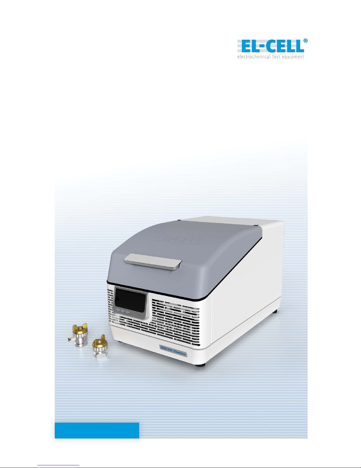
The PAT-Chamber-16 is a temperature controlled docking station / cell chamber for up to 16
test cells of the PAT series. The temperature of the chamber can be precisely controlled by
means of a Peltier device between 5 and 80°C. The PAT-Chamber-16 is the first high
throughput docking station supporting the PAT-Cell-Press for in-situ pressure monitoring of
up to 16 test cells at the same time.
The PAT-Chamber-16 is to be connected to a multi-channel potentiostat (like the Biologic
MPG-2) or battery tester (like the Maccor 4000). Mixed connection of the 16 cell positions to
different potentiostats / battery testers is possible as well.
The PAT-Chamber-16 features a built-in data logger for recording all cell signals – cell current,
cell voltage and the two half cell voltages of each cell – along with the chamber temperature
and the individual pressure signals, if used with the PAT-Cell-Press.
The PAT-Cell, the PAT-Core, and the EC-Link data logger software are covered in detail by
other manuals (http://el-cell.com/downloads/downloads-manuals
).
PAT-Chamber-16 and PAT-Chamber-1 6 C (with integrated PAT-Connect adapter box)
Features
Peltier temperature-controlled docking station, ready for connection to any potentiostat
or battery tester.
Temperature range 10 – 80°C
Holds up to 16 PAT series test cells for 2- and 3-electrode measurements.
Charge/discharge/EIS compatible with any PAT series test cell
Supports up to 16 PAT-Cell-Press for additional pressure monitoring
Compatible with all of today's multi-channel potentiostats and battery testers. Mixed
operation of the 16 cell positions with different potentiostats and/or battery testers
possible.
Integrated data logger hard- and software for recording of cell current, cell voltage, half
cell voltages, global temperature, and individual cell pressure.
Analog outputs available of the buffered half cell voltages (16 x V2R), sensor signals
(16 x AOUT) and chamber temperature (VT). The analog outputs allow for easy
interfacing with the external inputs of the connected battery tester / potentiostat.
Page 5 of 16
Release 1.0
User Manual P AT-Chamber-16
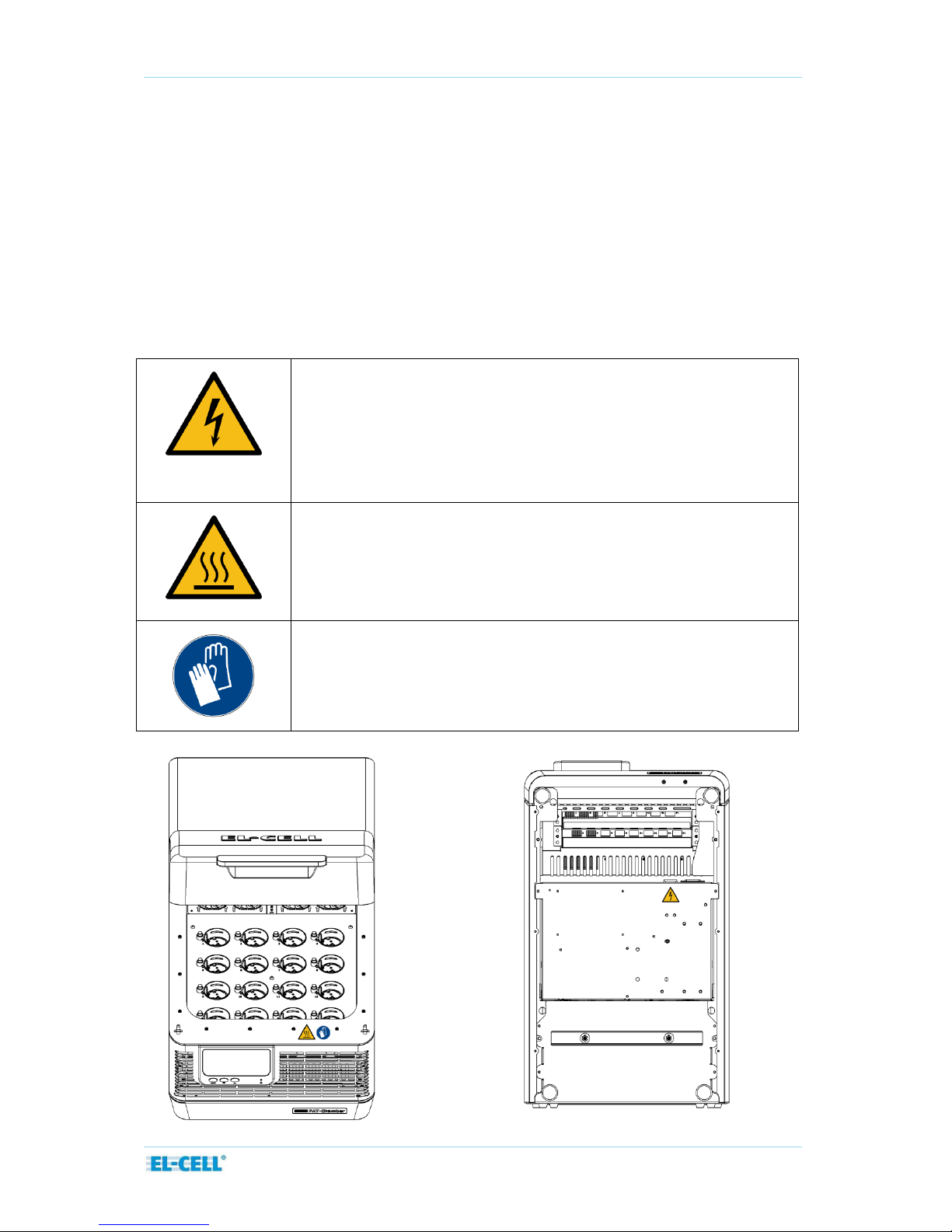
2 Safety instructions
The PAT-Chamber-16 should only be operated by laboratory personnel especially trained for
this purpose and familiar with all precautionary measures required for working in a laboratory .
To avoid injuries and damage observe the safety instructions of this user manual.
NOTE: The PAT-Chamber-16 must only be used with test cells of the PAT series. Don’t place other
goods inside the chamber.
2.1 Localization / position of safety labels on the PAT-Chamber-16
The following lables are located on the unit
Electrical hazard!
After removing covers, live parts may be exposed. You may receive
an electric shock if you touch these parts. Disconnect the mains plug
before removing any covers. Only electrical technicians may work on
the electrical equipment of the appliances.
Hot surface!
The parts of the inner chamber will become hot during operation.
Danger of burning. Do not touch the inner surfaces during operation
without protective gloves.
Wear protective gloves
Page 6 of 16
Release 1.0
User Manual P AT-Chamber-16
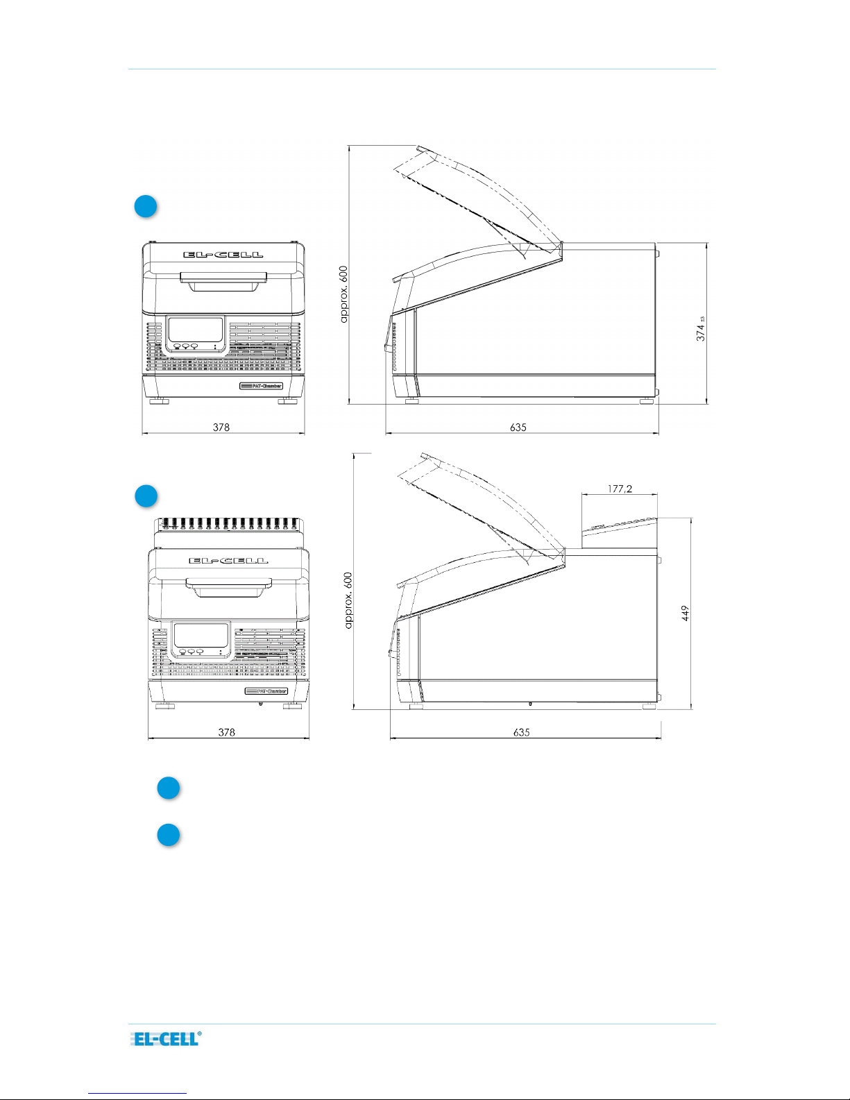
3 Technical data
Dimensions:
635 mm (width) x 378 mm (depth) x 374 mm (height)
Dimensions with attached PAT-Connect-16 C:
635 mm (width) x 378 mm (depth) x 449 mm (height)
Temperature: +10 to +80°C
Weight: 24 kg (without PAT-Cells)
1
2
1
2
Page 7 of 16
Release 1.0
User Manual P AT-Chamber-16
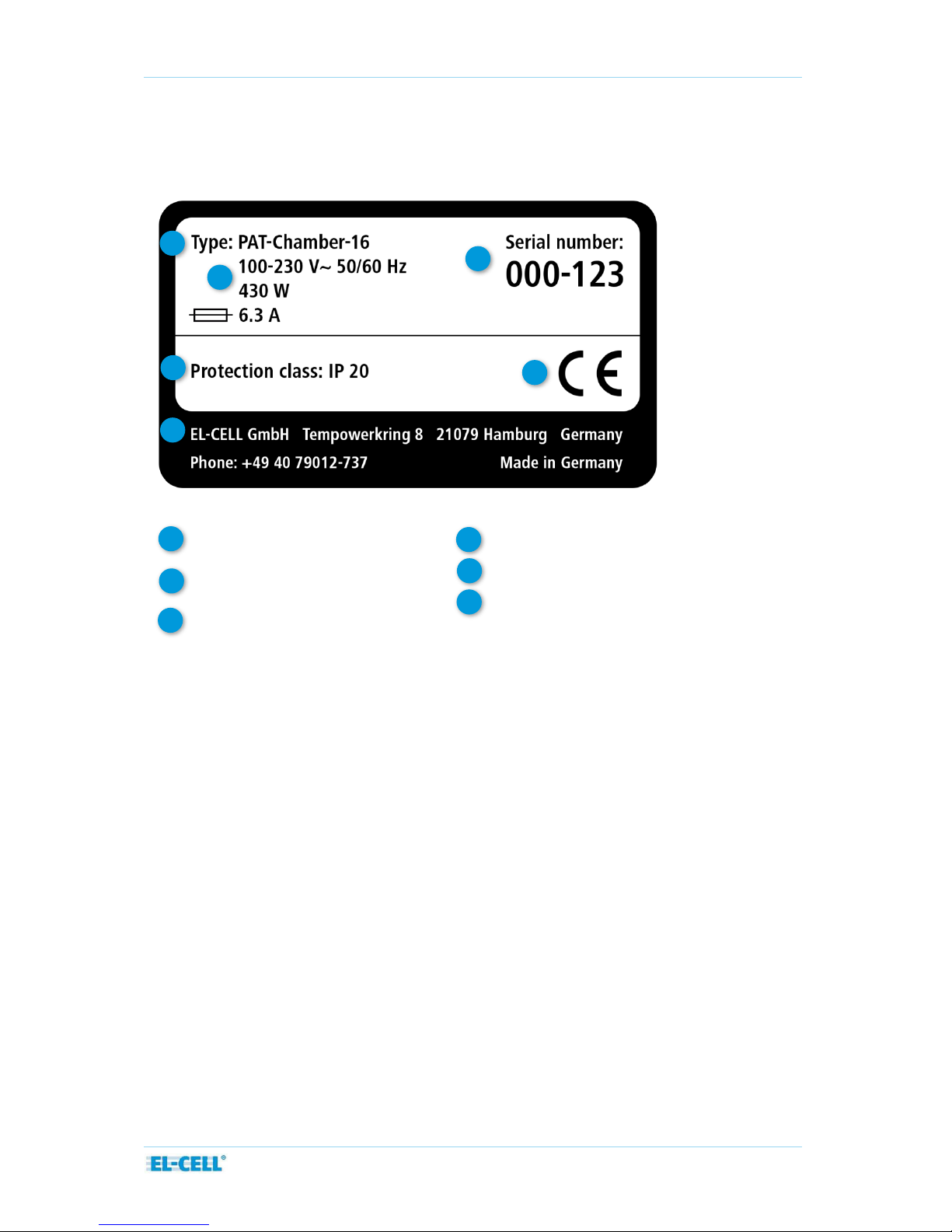
3.1 Designation (nameplate)
The nameplate provides information about the appliance model, manufacturer and technical
data. It is attached to the back of the appliance.
1 2 5
3
6
Type designation
Operating voltage,
Connection / power ratings
Protection class
1 3 2
Address of manufacturer
Serial number
CE conformity
4
6
5
4
Page 8 of 16
Release 1.0
User Manual P AT-Chamber-16
4 Installation
Place the PAT-Chamber-16 on a flat, horizontal surface. Do not place the instrument on a
flammable surface. A 230 V or 115 V power connection must be available. The distance
between the wall and the rear of the instrument must be at least 15 cm. The top clearance
must not be less than 25 cm. Sufficient air circulation in the vicinity of the instrument must be
guaranteed at all times.
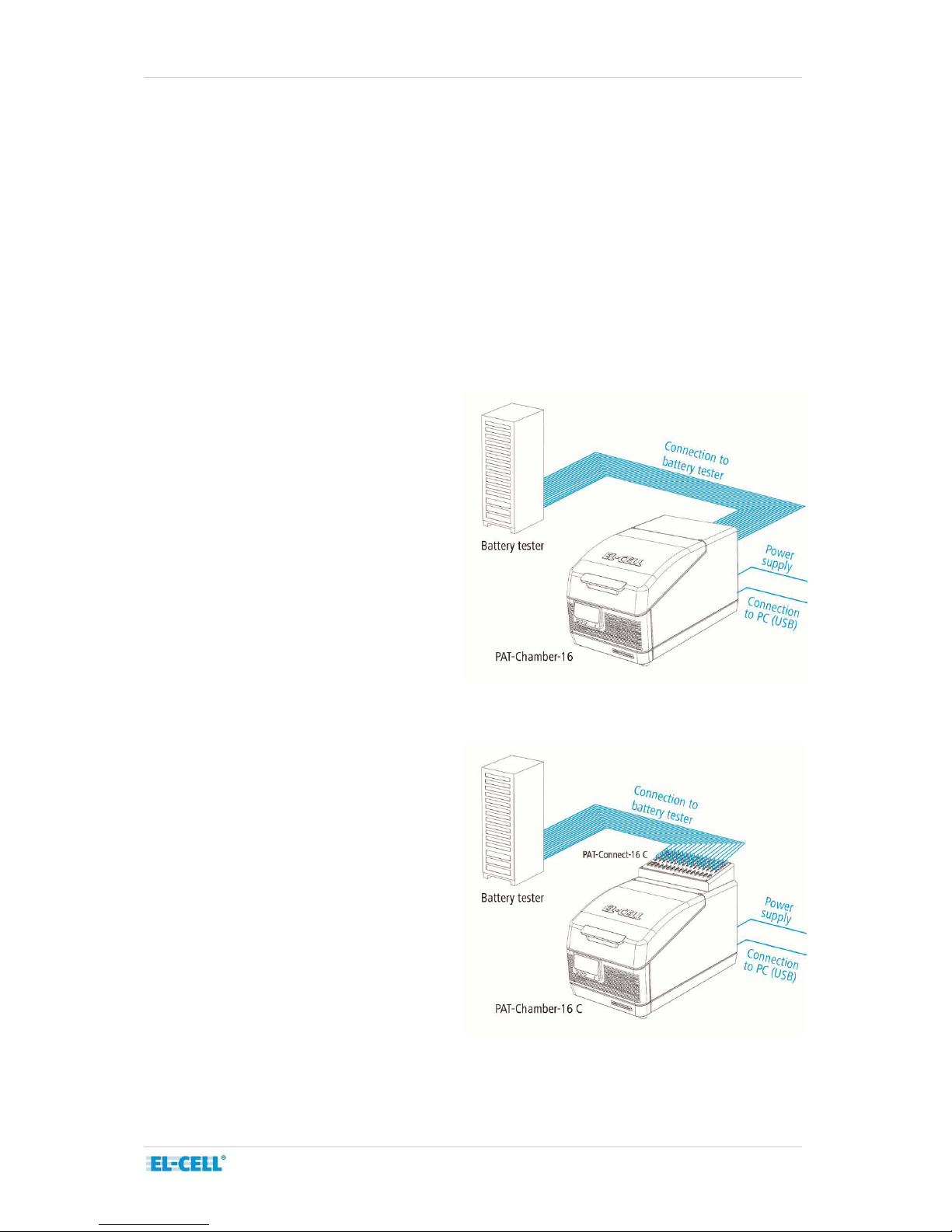
4.1 Connection to the external battery tester or potentiostat
Two versions of the PAT-Chamber-16 are available which differ in the way the connection to
the external battery tester or potentiostat is being established.
1. PAT-Chamber-16:
Direct connection with fixed
assignment of WE, CE and RE for a
given channel.
2. PAT-Chamber-16 C:
Indirect connection via
PAT-Connect-16 C with variable
assignment of WE, CE and RE for a
given channel.

Page 9 of 16
Release 1.0
User Manual P AT-Chamber-16
4.2 Connection to the power supply
Caution:
Observe the country-specific regulations when making connections. Observe the connection
and power ratings (see nameplate.). Make sure to establish a safe PE conductor connection.
Plug the provided power cable into the rear of the instrument. Lay the power cable so that it
is always accessible and within reach so it can be disconnected quickly in the event of failure
or emergencies.
Connect the other end of the power cable to the power supply (wall outlet). The instrument
will immediately power up once connected. Note that the cells docked into the PAT-Chamber16 will experience self-discharge (across a resistance of approx. 10 kOhm between WE and CE)
in case the instrument is powered down.
4.3 USB connection to the host PC
Plug one end of the provided USB cable into the USB socket at the rear of the PAT-Chamber16, the other end into the USB socket of the Windows PC. From the provided CD, install the
EC-Link software on the Windows PC and launch the EC -Link software.
For details of the software installation and operation, refer to the EC-Link software manual.
Note that the USB data logger hardware of the PAT-Chamber-16 is powered from the host PC,
and is galvanically isolated from the power supply of the PAT-Chamber.
Page 10 of 16
Release 1.0
User Manual P AT-Chamber-16
5 Operation
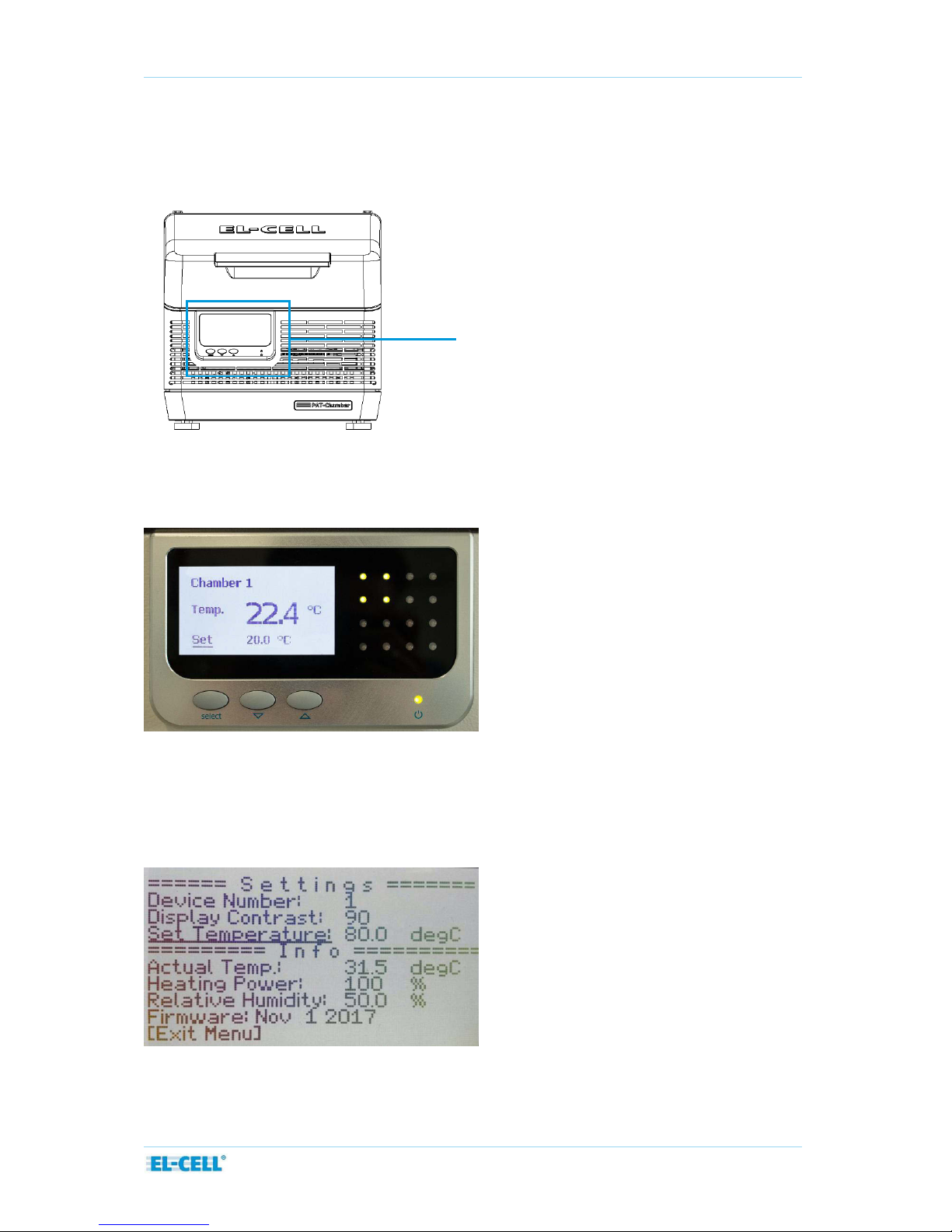
5.1 Control display, push buttons, and LED matrix
By default, the LC display at the front of the PAT-Chamber-16 shows the actual and the
setpoint temperature. The 4x4 LED matrix on the right informs about whether the
corresponding cell socket is free (LED off) or occupied (LED lit).
In order to change the setpoint temperature, press the select button, then adjust the
displayed setpoint with the arrow buttons, and confirm with the select button.
In order to change the device number or the display contrast, hold the select button for at
least one second. A settings list shows up. From this list, select the device or contrast entry
with the arrow buttons and change as required.
Control display
Page 11 of 16
Release 1.0
User Manual P AT-Chamber-16
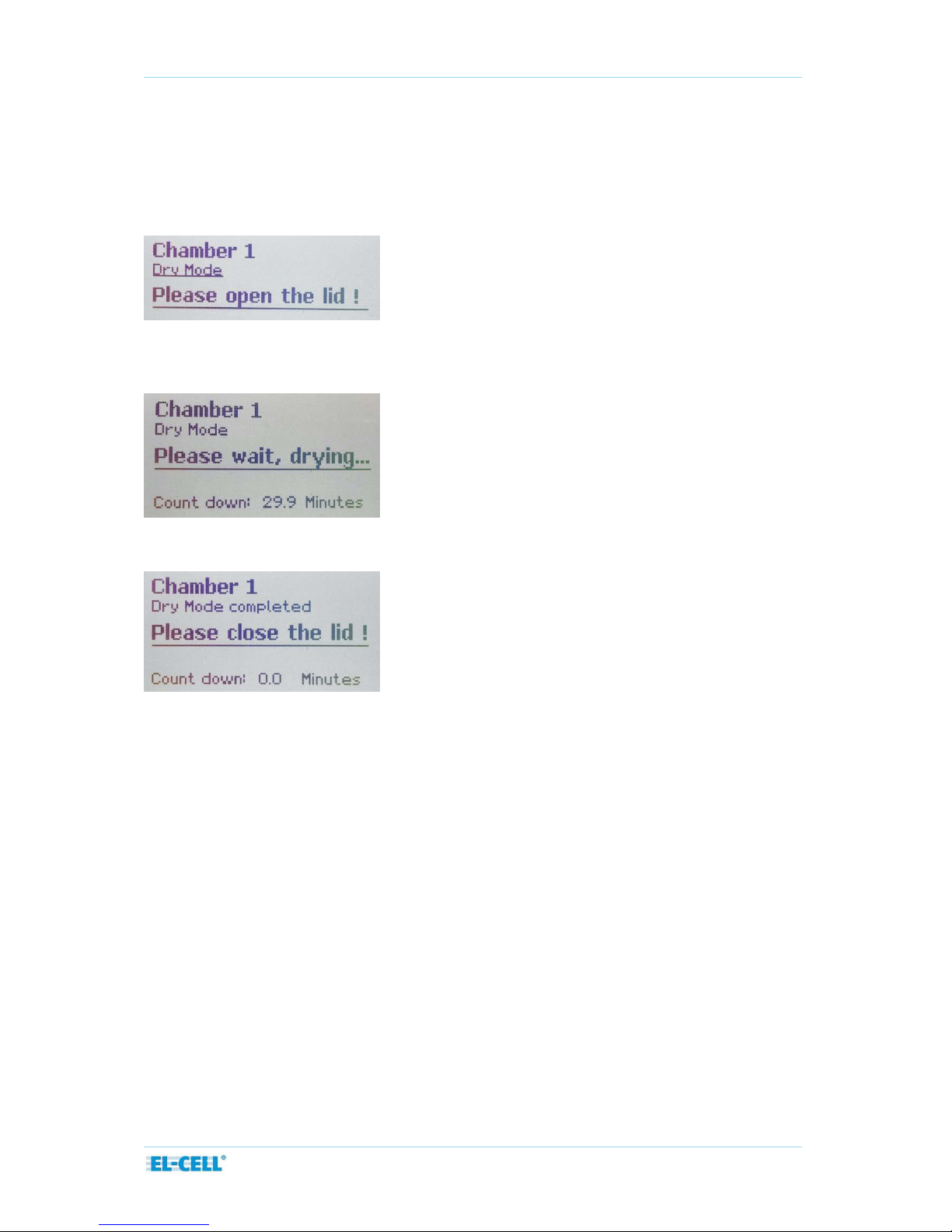
5.2 Dry Mode
Under certain operating conditions, especially when heating up the chamber from a setpoint
below ambient temperature, water may start to condense inside the chamber. When detecting
such an operating condition, the chamber automatically enters the so -called Dry Mode: The user
is prompted to open the lid of the PAT-Chamber.
Once the lid has been opened, the user is prompted to wait (to lea ve the chamber open) for a
given time period.
Once the countdown is finished, the user is prompted to close the lid.
5.2 Workflow
This section gives a quick overview on how to run a test with a PAT -Cell docked into the PATChamber, and connected to an external battery tester. More details on the EC-Link software
are given in a separate manual.
─ Open the cover of the PAT-Chamber
─ Insert a new PAT-Cell into a free socket, and close the cover.
─ In EC-Link, a menu pops up, notifying that a new test cell has been inserted.
─ Follow the instructions of the ‘New cell detected’ dialog. Data recording for the given
cell will be started.
─ In the software application of the battery tester, start the test procedure of the
corresponding channel.
─ Once the test is completed, remove the PAT-Cell from the PAT-Chamber.
─ In EC-Link, a menu pops up, notifying that recording has been stopped.

Page 12 of 16
Release 1.0
User Manual P AT-Chamber-16
6 EC-Link software
How to install and operate with the EC-Link software is described in a separate manual.
Please note that the EC-Link software is only required for the standard configuration of the
PAT-Chamber-16, which contains a data logger. A passive version of the PAT-Chamber-16
without a data logger is available on request.
7 Cleaning
Wipe the PAT-Chamber-16 with a moist tissue. Do not use aggressive chemicals for cleaning.
Protect the PAT-Chamber-16 from dust and splash water.
8 Unpacking
Check the contents of the packages against the list given below to verify that you have
received all of the required components. Contact EL-CELL, if anything is missing or damaged.
NOTE: Damaged shipments must remain within the original packaging for freight company
inspection.
List of c
omponents
PAT-Chamber-16 ECC1-03-0300-A
optionally with PAT-Connect-16 C ECC1-03-0130-A
Power cord ELT9412
USB cable (Type A/B; 2,0m) ELT9167
EC-Link installation CD ECE1-00-0052-A
NOTE: The cables for connection between PAT-Chamber-16 and the external battery tester
must be ordered separately.

Page 13 of 16
Release 1.0
User Manual P AT-Chamber-16
10 EC declaration of conformity

Page 14 of 16
Release 1.0
User Manual P AT-Chamber-16
The products described are in conformity with the following harmonized standards:
EN 61010-1:2010
Sicherheitsbestimmungen für elektrische Mess-, Steuer-,
Regel- und Laborgeräte – Teil 1: Allgemeine Anforderungen
(DIN EN 61010-1, VDE 0411-1:2011-07)
Safety requirements for electrical equipment for
measurement, control and laboratory use - Part 1: General
requirements
(IEC 61010-1:2010 + Cor. :2011)
EN 61010-2-201:2014
Sicherheitsbestimmungen für elektrische Mess-, Steuer-,
Regel- und Laborgeräte - Teil 2-201: Besondere
Anforderungen für Steuer- und Regelgeräte
(DIN EN 61010-2-201:2014, VDE 0411-2-201:2014-01)
Safety requirements for electrical equipment for
measurement, control and laboratory use - Part 2-201:
Particular requirements for control equipment
(IEC 61010-2-201:2013)
EN 61010-2-010:2015-05
Sicherheitsbestimmungen für elektrische Mess-, Steuer-,
Regel- und Laborgeräte - Teil 2-010: Besondere
Anforderungen an Laborgeräte für das Erhitzen von Stoffen
(DIN EN 61010-2-010:2014; VDE 0411-2-010:2015-05)
Safety requirements for electrical equipment for
measurement, control and laboratory use - Part 2-201:
Particular requirements for control equipment
(IEC 61010-2-201:2013)
EN 61326-1:2013
Elektrische Mess-, Steuer-, Regel- und Laborgeräte - EMVAnforderungen - Teil 1: Allgemeine Anforderungen
(DIN EN 61326-1:2013-07, VDE 0843-20-1:2013-07)
EMC requirements - Part 2-3: Particular requirements - Test
configuration, operational conditions and performance criteria
for transducers with integrated or remote signal conditioning
(IEC 61326-2-3:2012)

Page 15 of 16
Release 1.0
User Manual P AT-Chamber-16
EN 61326-2-3:2013-07
Elektrische Mess-, Steuer-, Regel- und Laborgeräte - EMVAnforderungen - Teil 2-3: Besondere Anforderungen Prüfanordnung, Betriebsbedingungen und Leistungsmerkmale
für Messgrößenumformer mit integrierter oder abgesetzter
Signalaufbereitung
(DIN EN 61326-2-3:2013-07, VDE 0843-20-2-3:2013-07)
Electrical equipment for measurement, control and laboratory
use - EMC requirements - Part 2-3: Particular requirements Test configuration, operational conditions and performance
criteria for transducers with integrated or remote signal
conditioning
(IEC 61326-2-3:2012)
EN 50581: 2013-02
Technische Dokumentation zur Beurteilung von Elektro- und
Elektronikgeräten hinsichtlich der Beschränkung gefährlicher
Stoffe
(DIN EN 50581; VDE 0042-12:2013-02)
Technical documentation for the assessment of electrical and
electronic products with respect to the restriction of
hazardous substances

Page 16 of 16
Release 1.0
User Manual P AT-Chamber-16
11 Technical support
Technical support for this product is exclusively provided by EL-CELL GmbH.
EL-CELL GmbH
Tempowerkring 8
21079 Hamburg - Germany
phone: +49 40 79012-737
fax: +49 40 79012-736
e-mail: info@el-cell.com
web: www.el-cell.com
12 Warranty
For a period of one year from the date of shipment, EL-CELL GmbH (hereinafter Seller)
warrants the goods to be free from defect in material and workmanship to the original
purchaser. During the warranty period, Seller agrees to repair or replace defective and/or
nonconforming goods or parts without charge for material or labor, or, at the Seller’s option,
demand return of the goods and tender repayment of the price. Buyer’s exclusive remedy is
repair or replacement of defective and nonconforming goods, or, at Seller’s option, the
repayment of the price.
Seller excludes and disclaims any liability for lost profits, personal injury, interruption of
service, or for consequential incidental or special damages arising out of, resulting from, or
relating in any manner to these goods.
This Limited Warranty does not cover defects, damage, or nonconformity resulting from
abuse, misuse, neglect, lack of reasonable care, modification, or the attachment of improper
devices to the goods. This Limited Warranty does not cover expendable items. This warranty is
void when repairs are performed by a non-authorized person or service center. At Seller’s
option, repairs or replacements will be made on site or at the factory. If repairs or
replacements are to be made at the factory, Buyer shall return the goods prepaid and bear all
the risks of loss until delivered to the factory. If Seller returns the goods, they will be delivered
prepaid and Seller will bear all risks of loss until delivery to Buyer. Buyer and Seller agree that
this Limited Warranty shall be governed by and construed in accordance with the laws of
Germany.
The warranties contained in this agreement are in lieu of all other warranties expressed or
implied, including the warranties of merchantability and fitness for a particular purpose.
This Limited Warranty supersedes all prior proposals or representations oral or written and
constitutes the entire understanding regarding the warranties made by Seller to Buyer. This
Limited Warranty may not be expanded or modified except in writing signed b y the parties
hereto.

© 2017 EL-CELL GmbH
User Manual
Release 1.0
PAT-Connect-16
Adapter box for flexible wiring connections

Page 2 of 10
Release 1.0
User Manual PAT-Connect-16
The information in this manual has been carefully checked and believed to be accurate;
however, no responsibility is assumed for inaccuracies.
EL-CELL GmbH maintains the right to make changes without further notice to products
described in this manual to improve reliability, function, or design. EL -CELL GmbH does not
assume any liability arising from the use or application of this product.
EL-CELL GmbH
Tempowerkring 8
21079 Hamburg - Germany
phone: +49 40 79012-737
fax: +49 40 79012-736
e-mail: in fo@ el- cel l.c om
web: www.el-cell. com

Page 3 of 10
Release 1.0
User Manual PAT-Connect-16
Content
1 Product description ...................................................................................................................................... 4
2 Technical data ................................................................................................................................................ 5
3 Installation....................................................................................................................................................... 6
4 Cleaning ........................................................................................................................................................... 8
5 Unpacking ....................................................................................................................................................... 9
6 Accessories ...................................................................................................................................................... 9
7 Technical support ........................................................................................................................................ 10
8 Warranty ........................................................................................................................................................ 10

Page 4 of 10
Release 1.0
User Manual PAT-Connect-16
1 Product description
The PAT-Connect-16 box serves the most flexible connection between an external battery
tester or multi-channel potentiostat and the PAT-Stand-16/PAT-Chamber-16. The individual
connection between a given PAT-Cell in the stand /chamber and the corresponding channel of
the battery tester can be configured via an array of banana sockets at the front of the
connection box. That gives the largest possible freedom to choose between the various full
and half cell control modes.
In addition, the PAT-Connect box feeds through all the auxiliary analog signals provided by
the PAT series test cells - temperature, pressure and buffered half cell voltages - and makes
these signals available to the external battery tester.
Two different versions of the PAT-Connect-16 are available:
The PAT-Connect-16 for connection to the PAT-Stand-16. This version is for wall
mounting or placing on the bench.
The PAT-Connect-16 C for connection to the PAT-Chamber-16. This version is
permanently attached to the PAT-Chamber.
Features
Easy-to-access banana sockets for plug-in of the cell cables of the battery tester /
potentiostat (sockets available for WE, WE-Sense, RE, CE, CE-Sense, and GND)
Sub-D Connector for optional auxiliary signals: buffered half cell voltages, temperature,
sensor signals
Available as modular box (PAT-Connect-16) to be placed on the bench or fixed on the
wall, or as an attachment on top of the PAT-Chamber-16 C (PAT-Connect-16 C)
PAT-Connect-16-C
PAT-Connect-16
1 1 2
2

Page 5 of 10
Release 1.0
User Manual PAT-Connect-16
2 Technical data
Dimensions PAT-Connect-16:
334 mm (width) x 195 mm (depth) x 106 mm (height)
Dimensions PAT-Connect-16 C:
350 mm (width) x 177 mm (depth) x 75 mm (height)

Page 6 of 10
Release 1.0
User Manual PAT-Connect-16
3 Installation
When purchased in combination with a PAT-Stand-16 or PAT-Chamber-16, the PAT-Connect
box comes always readily connected upon delivery. The connection cables between docking
station and connect box are available in different lengths:
PAT-Connect-16 Cable Set (10/10), 700 mm length, ECE1-00-0152-A
PAT-Connect-16 Cable Set (10/10), 1000mm length, ECE1-00-0152-
B
PAT-Connect-16 Cable Set (10/10), 2000 mm l ength, ECE1-00-0152-C

Page 7 of 10
Release 1.0
User Manual PAT-Connect-16
3.1 PAT-Connect-16 connections
3.2 Control modes
The following schemes show how to connect, for a given test channel, the cell cable of the
external battery tester or potentiostat to the banana sockets at the PAT-Connect box. Note
that the naming conventions for the cell cable signals, and the number of signals (between 3
and 5), may differ between battery testers. The leads WE, CE and RE are always present, albeit
possibly with other names.
1. Full cell control
2. Half cell control 1 vs R (lower half cell)
Battery tester /
potentiostat
WE
CE
RE
WE Sense
CE Sense
PAT-Connect-16
1 2 2S
1S
2S
Battery tester /
potentiostat
WE
CE
RE
WE Sense
CE Sense
PAT-Connect-16
1 2 R
1S
2S
4mm banana sockets
1 (Lo wer electrode)
2 (Upper electrode)
RE (Reference electrode)
1S (Sense 1)
2S (Sense 2)
GND (Ground)
Sub-D Connector
Optional auxiliary signals, e.g.:
- sensor signals
- t emperature
- buffered half cell volta ge s

Page 8 of 10
Release 1.0
User Manual PAT-Connect-16
3. Half cell control 2 vs R (upper half cell)
The connection namings mentioned in the operation mode tables can differ from the used
potentiostat. To view specific naming conventions from selected different manufacturers see
the table below.
Important note: The application of our test cells is not limited to the potentiostats listed
below. Our test cells can be used with all other potentiostats as well.
4 Cleaning
Wipe the PAT-Connect-16 with a moist tissue. Do not use aggressive chemicals for cleaning.
Protect the device from dust and moisture.
Battery tester /
potentiostat
WE
CE
RE
WE Sense
CE Sense
PAT-Connect-16
2 1 R
2S
1S
3.3 Cable colors and naming conventions
Exemplary
potentiostat
WE
WE-Sense
CE
CE-Sense
RE
BioLogic
(i.e. VSP, VMP3)
WE
Red cable
Ref1
Red cable
CE
Blue cable
Ref3
Blue cable
Ref2
White cable
Gamry Instruments
(i.e. Reference 3000TM)
Green cable
Blue cable
Red cable
Orange cable
White cable
Ivium Technologies
(i.e. IviumStat)
WE1
Red cable
S
White cable
CE
Black cable
-
RE
Blue cable
Metrohm Autolab
(i.e. PGSTAT Series)
WE
Red cable
S
Red cable
CE
Black cable
-
RE
Blue cable
Princeton Applied
Research
(i.e. PARSTAT 2273)
Green cable
Grey cable
Red cable
-
White cable

Page 9 of 10
Release 1.0
User Manual PAT-Connect-16
5 Unpacking
Check the contents of the packages against the list given below to verify that you have
received all of the required components. Contact EL-CELL, if anything is missing or damaged.
NOTE: Damaged shipments must remain within the original packaging for freight company
inspection.
List of components
P
AT-Connect-16 ECE1-00-0130-A or PAT-Connect-16 C ECC1-03-0130-A
NOTE: The cables for connection between PAT-Chamber-16/PAT-Stand-16 and the PAT-
Connect-16 must be ordered separately.
6 Accessories
Adapter male 4 mm to female 2 mm, black (10pcs) ELT9081/X

Page 10 of 10
Release 1.0
User Manual PAT-Connect-16
7 Technical support
Technical support for this product is exclusively provided by EL-CELL GmbH.
EL-CELL GmbH
Tempowerkring 8
21079 Hamburg - Germany
phone: +49 40 79012-737
fax: +49 40 79012-736
e-mail: in fo@ el- cel l.c om
web: www.el-cell. com
8 Warranty
For a period of one year from the date of shipment, EL -CELL GmbH (hereinafter Seller)
warrants the goods to be free from defect in material and workmanship to the orig inal
purchaser. During the warranty period, Seller agrees to repair or replace defective and/or
nonconforming goods or parts without charge for material or labor, or, at the Seller’s option,
demand return of the goods and tender repayment of the price. Buy er’s exclusive remedy is
repair or replacement of defective and nonconforming goods, or, at Seller’s option, the
repayment of the price.
Seller excludes and disclaims any liability for lost profits, personal injury, interruption of
service, or for consequential incidental or special damages arising out of, resulting from, or
relating in any manner to these goods.
This Limited Warranty does not cover defects, damage, or nonconformity resulting from
abuse, misuse, neglect, lack of reasonable care, modification, or the attachment of improper
devices to the goods. This Limited Warranty does not cover expendable items. This warranty is
void when repairs are performed by a non-authorized person or service center. At Seller’s
option, repairs or replacements will be made on site or at the factory. If repairs or
replacements are to be made at the factory, Buyer shall return the goods prepaid and bear all
the risks of loss until delivered to the factory. If Seller returns the goods, they will be delivered
prepaid and Seller will bear all risks of loss until delivery to Buyer. Buyer and Seller agree that
this Limited Warranty shall be governed by and construed in accordance with the laws of
Germany.
The warranties contained in this agreement are in lieu of all other warranties expressed or
implied, including the warranties of merchantability and fitness for a particular purpose.
This Limited Warranty supersedes all prior proposals or representations oral or written and
constitutes the entire understanding regarding the warranties made by Seller to Buyer. This
Limited Warranty may not be expanded or modified except in writing signed by the parties
hereto.

© 2017 EL-CELL GmbH
Quick Guide
EC-Link Software
Release 2.5
Using with PAT-Tray, PAT-Stand-16, PAT-Chamber-16

Page 2 of 12
Quick Guide EC-Link-Software (PAT-Tray, PAT-Stand-16, PAT-Chamber-16)
Release 2.5
The information in this manual has been carefully checked and believed to be accurate;
however, no responsibility is assumed for inaccuracies.
EL-CELL GmbH maintains the right to make changes without further notice to products
described in this manual to improve reliability, function, or design. EL -CELL GmbH does not
assume any liability arising from the use or application of this product.
EL-CELL GmbH
Tempowerkring 8
21079 Hamburg - Germany
phone: +49 (0)40 790 12 733
fax: +49 (0)40 790 12 736
e-mail: info@el-cell.com
web: www.el-cell.com

Page 3 of 12
Quick Guide EC-Link-Software (PAT-Tray, PAT-Stand-16, PAT-Chamber-16)
Release 2.5
Content
1 What is EC-Link? ............................................................................................................................................ 4
2 EC-Link System Requirements ................................................................................................................... 4
3 Installing the EC-Link Software ................................................................................................................. 4
4 Running the EC-Link Software ................................................................................................................... 5
5 Log files ............................................................................................................................................................ 8
6 Settings .......................................................................................................................................................... 10
7 Post-Process ................................................................................................................................................. 11
8 Running Multiple Data Loggers .............................................................................................................. 12
9 Upgrading EC-Link ...................................................................................................................................... 12

Page 4 of 12
Quick Guide EC-Link-Software (PAT-Tray, PAT-Stand-16, PAT-Chamber-16)
Release 2.5
1 What is EC-Link?
EC-Link is the data logger software coming with the following instruments .
PAT-Stand-16/PAT-Tray (docking station for up to 16 PAT-Cells)
PAT-Chamber-16
PAT-Press, ECC-Press-DL, ECD-2-DL, ECD-3, ECD-nano-DL, ECD-3-nano (please refer to
separate quick start guide)
With the EC-Link software, the signals of the cells attached to the PAT-Stand-16 or PATChamber-16 are recorded into log files and viewed as strip-charts. One set of files is being
created for each of the 16 test cells. Th e files contain the cell signal data of the given cell –
current, cell voltage and the two half cell voltages – together with the temperature of the
docking station. If the PAT-Chamber-16 is used with the PAT -Cell-Press, the files also contain
the pressure data of the respective test cell. EC-Link employs an highly efficient data
reduction algorithm to create a compressed log file from the raw data stream. In addition, the
software computes cycle-wise integrated and differential capacity data and stores them in
separate result files.
Connection between the PC host and the data logger is being established via USB. Multiple
instruments and associated instances of the EC-Link software can be run in parallel on the
same PC. The EC-Link software is licence-free. Updates are regularly available at no charge.
2 EC-Link System Requirements
You can install the EC-Link software on any computer running one of these operating systems:
Windows 8, Windows 7, Windows Vista, Windows XP (SP2 or later).
3 Installing the EC-Link Software
1. You must be logged into an account with administrator privileges.
2. Save your work and close down all active programs.
3. On the installation CD, run X:\setup. This will install the EC-Link software. Follow any
instructions that may appear on your screen.
4. Once installation is finished, plug in the provided USB cable into both the host PC and
the instrument’s controller box. When connecting the hardware for the first time,
Windows will automatically install the driver.
5. Launch the EC-Link software if you have not already done.
6. After a few seconds, the EC-Link software should report a valid connection and you are
ready to start the log.

Page 5 of 12
Quick Guide EC-Link-Software (PAT-Tray, PAT-Stand-16, PAT-Chamber-16)
Release 2.5
4 Running the EC-Link Software
The EC-Link software continuously acquires data at a fixed rate of about 1 Hz. The signals of
the inserted test cells are displayed in strip charts, one chart for each cell. If no test cell is
inserted, the corresponding channels are displayed as zero. Data recording can be started for
an inserted test cell only.
The insertion and recording status of all cell positions is given in the test cell table .
1. Data recording for a given cell can be started in two ways.
Insert a new cell into the docking station and follow the instructions of the ‘ New
cell detected’ dialog.
Press the ‘Record’ button of a cell which has been inserted previously and has
not been started at that time.
1
2
3
4
1
2

Page 6 of 12
Quick Guide EC-Link-Software (PAT-Tray, PAT-Stand-16, PAT-Chamber-16)
Release 2.5
In either case, the program will open the ‘Battery Data Processing’ dialog asking for the
parameters required to calculate additional “secondary” data from the primary (raw)
data. The default setting will be appropriate in most cases. Details on the different log
files created for each measurement are given in chapter 5.
‘Cycle starts with charge (current > 0)’ applies to full cells (such as LCO vs Graphite)
and “cathode” half cells (such as LCO vs Lithium). ‘Cycle starts with discharge
(current < 0)’ applies to “anode” half cells (such as Graphite vs Lithium). This
parameter is required to distinguish between cycles.
‘threshold current’ refers to the absolute value of the current considered as zero.
This parameter is required to detect start and end of cycles. For proper detection,
the chosen threshold must be larger than the total error of the measured current.
‘dV’ refers to the voltage difference V used by the software to calculate the
differential capacitance Q/V from the primary data. The smaller V is chosen, the
better gets the voltage resolution, but the larger the noise of the calculated
capacitance values.
‘(di/dt)_min’ refers to the minimum change of current, below which the algorithm
considers the current as constant. Only at constant current, the differential
capacitance values are being calculated.

Page 7 of 12
Quick Guide EC-Link-Software (PAT-Tray, PAT-Stand-16, PAT-Chamber-16)
Release 2.5
2. Checkmark the channels you want to view . This setting will apply to all cells.
3. Choose the test cell , the strip chart of which you want to view. With the mouse
wheel, you can scroll through the test cells.
4. Select the active y-axis of the strip charts by clicking on the respective channel name or
on the channel trace in the chart.
5. For a given channel, y-min and y-max define the vertical limits of the displayed trace.
Choosing y-min larger than y-max will reverse the y-axis.
6. Clicking the ‘Autoscale selected Channel’ button will affect the data of all inserted cells
in the presently displayed time window.
7. Click the ‘View file’ button in the headline to view the log file data of the selected
channel in text format.
8. Double-click on a channel name to display the current readi ng in large characters
(multimeter mode).
9. Data recording of a given test cell can be stopped in two ways. In either case the
corresponding log files will be closed.
Press the ‘Stop’ button of the test cell, or
remove the test cell from the docking station.
10. Data recording can be paused by clicking, in the test cell table, the ‘Pause’ button of the
respective test cell, and resumed by clicking the ‘Resume’ button. This way the test cell
can be temporarily removed from the docking station without having to create a second
set of log files when resuming the measurement.
3
4

Page 8 of 12
Quick Guide EC-Link-Software (PAT-Tray, PAT-Stand-16, PAT-Chamber-16)
Release 2.5
5 Log files
For a given measurement, EC-Link generates six different log files.
*.txt contains the uncompressed (primary) data with constant time interval between data
rows.
Format (Columns):
─ Sample (optional)
─ Date and Time (optional)
─ Time (s) (since measurement start)
─ Time UTC (s) (since 1970, optional)
─ Current (mA) (cell current in mA)
─ V12 (V) (cell voltage in V)
─ V1R (V) (half cell voltage 1 vs R)
─ V2R (V) (half cell voltage 2 vs R)
─ T (°C) (temperature)
─ Pressure (bar) or Dilation (µm)
─ Cycle
─ t_cycle (s) (time of given cycle)
─ P (mW) (power)
─ Qtot (mAh) (charge obtained by integration of current over time)
─ Qcd (mAh) (same as Qtot, but nulled at start of each half cycle)
─ |Qcd| (mAh) (absolute value of Qcd)
─ Qc (mAh) (charge of positive half cycle, nulled at start of half cycle)
─ Qd (mAh) (|charge| of negative half cyclenulled at start of half cycle)
─ Wcd (mWh) (energy, nulled at start of each half cycle)
*_Small.txt contains the reduced (compressed) data with varying time interval between
data rows. Format: same as *.txt
*-Cycle.txt contains the “cycle-wise” computed integral data
Format (Columns):
─ Cycle
─ Time (s)
─ Qc (mAh) (charge of positive half cycle)
─ Qd (mAh) (|charge| of negative half cycle)
─ Wc (mWh) (energy of positive half cycle)
─ Wd (mWh) (|energy| of negative half cycle)

Page 9 of 12
Quick Guide EC-Link-Software (PAT-Tray, PAT-Stand-16, PAT-Chamber-16)
Release 2.5
─ Qd/Qc (charge efficiency)
─ Wd/Wc (energy efficiency)
*-C12.txt contains the differential capacitance data of the full cell
─ Format (Columns):
─ Cycle
─ Time (s)
─ t_cycle (s)
─ V12 (V)
─ Delta V12 (V)
─ Delta Q (mAh)
─ C12=|Delta Q|/Delta V12 (mAh/V)
*-C1R.txt contains the differential capacitance data of the positive ha lf cell
Format (Columns):
─ Cycle
─ Time (s)
─ t_cycle (s)
─ V1R (V)
─ Delta V1R (V)
─ Delta Q (mAh)
─ C1R=|Delta Q|/Delta V1R (mAh/V)
*-C2R.txt contains the differential capacitance data of the negative half cell
Format (Columns):
─ Cycle
─ Time (s)
─ t_cycle (s)
─ V2R (V)
─ Delta V2R (V)
─ Delta Q (mAh)
─ C2R=|Delta Q|/Delta V2R (mAh/V)
In addition to the six log files with the file extension “.txt”, EC-Link generates a single empty
file *.patmsr.

Page 10 of 12
Quick Guide EC-Link-Software (PAT-Tray, PAT-Stand-16, PAT-Chamber-16)
Release 2.5
6 Settings
The settings of the EC-Link software being specific to the instrument are contained in the file
C:\ProgramData\EC-Link\Settings… A copy of this file can also be found on the installation CD
and may be used to restore the original settings. Within the progr am, in the
Settings/Calibration dialog, you can only modify the number of decimal digits displayed, the
colours of the individual traces, and the maximum error E of the data reduction algorithm.
The ‘Reduction Algo max Error’ E has a great impact on the efficiency of the data reduction
and hence on the size of the compressed * _Small.txt log file. In short, the algorithm checks if
a given data point is more than E off the straight line connecting two adjacent data points. If
so, then the given data point is kept in *_Small.txt, otherwise it is discarded. Note that the
algorithm is applied to all channels. Therefore, if E is set to zero for any channel, then no
data reduction takes place.
In the Settings/Program dialog, you can select additional columns to be logged into the *.txt
and *_Small.txt log files. The UTC time format is especially useful in case different consecutive
measurements need to be referred to the same time scale.

Page 11 of 12
Quick Guide EC-Link-Software (PAT-Tray, PAT-Stand-16, PAT-Chamber-16)
Release 2.5
7 Post-Process
In the headline of the program window, click the ‘Post-Process’ button in order to re-process
existing *.txt log files using new processing parameters. Note that this function can only be
applied on the original (uncompressed) *.txt log files.
The Post Process dialog prompts for the maximum error of the r educed data written into the
*_Small.txt log file, and for the parameters used to create the cycle-wise integrated data (* Cycle.txt) and the differential capacitance data (*-C12.txt, *-C1R.txt and *-C2R.txt). For more
details on these parameters refer to chapter 4.

Page 12 of 12
Quick Guide EC-Link-Software (PAT-Tray, PAT-Stand-16, PAT-Chamber-16)
Release 2.5
8 Running Multiple Data Loggers
It is possible to connect multiple USB data loggers (and associated instruments) to a single PC
and to run them simultaneously. The EC-Link software only needs to be installed once.
For the installation of an additional device, just copy the settings file from the provided
installation CD of the new instrument into the directory C:\ProgramData\EC-Link. Note that
the directory C:\ProgramData\ may be hidden by default.
9 Upgrading EC-Link
When upgrading the EC-Link software from version 2.0 or higher, we recommend the
following procedure.
Download and unzip the newest software from https://el-cell.com/support/software
Run setup.exe and overwrite the existing directory C: \Program Files\EC-Link
When upgrading the EC-Link software from a version below 2.0, we recommend the following
procedure.
Download and unzip the newest softwar e from https://el-cell.com/support/software
Run setup.exe
Launch (double-click) EC-Link, and choose the appropriate setting file from the provided
list. This settings file will be copied to the directory C:\ProgramData\EC-Link.
Follow the instructions on the screen. Notice the 8-digit device number ‘ADX…..’ as
displayed in the status window.
Quit the software and manually rename the settings file in the directory
C:\ProgramData\EC-Link into ‘Settings…[ADX…..]. The device number will be used by the
software to unambiguously assign the settings file to the corresponding instrument.
For housekeeping reasons, delete any unused setting files from the directory
C:\ProgramData\EC-Link. Also uninstall any older EC-Link program versions.
 Loading...