

User manual
MITO
Industrial radio remote control
AT MITO-VETTA-915
Transmitting Unit
AR MITO-MINI-915
Receiving Unit
ELCA S.r.l.
MULTI man MITO-VETTA 915 00
Via del Commercio, 7/b - 36065 Mussolente (VI) ITALY
www.elcaradio.com tel. +39 0424 578500 fax +39 0424 578520
0408MA000557

User manual
ENGLISH

ENG man MITO-VETTA 915 00 Radio Remote Control System MITO-VETTA-915
INDEX
a. FEDERAL COMMUNICATIONS COMMISSION (FCC) CONFORMITY AND FREQUENCIES .II
a.1 CONFORMITY ................................................................................................................................................... II
a.2 FCC CONFORMITY STATEMENT ............................................................................................................... II
a.3 FREQUENCIES ................................................................................................................................................. II
a.4 MARKET .............................................................................................................................................................. II
1. USER MANUAL .................................................................................................................................................. 1
2. USE INSTRUCTIONS ........................................................................................................................................ 2
2.1 GENERAL INFORMATION ............................................................................................................................. 2
2.2 APPLICATIONS AND USE CONDITIONS NOT PERMITTED ............................................................ 2
2.3 INSTRUCTIONS FOR PROPER AND SAFE USE .................................................................................. 3
2.4 TRANSMITTING UNIT AT MITO-VETTA-915 ........................................................................................... 4
2.5 RECEIVING UNIT AR MITO-MINI-915 ....................................................................................................... 5
2.6 STORING ACCESS CODES ......................................................................................................................... 6
2.7 INFORMATION FOR MAINTENANCE ....................................................................................................... 8
2.8 INFORMATION FOR THE PROPER INSTALLATION OF THE RADIO REMOTE CONTROL
SYSTEM ........................................................................................................................................................................ 8
2.9 WARRANTY ........................................................................................................................................................ 9
2.10 DISPOSAL INFORMATION ............................................................................................................................ 9
ENGLISH
3. PROGRAMMABLE FUNCTIONS ................................................................................................................10
3.1 ACCESS TO PROGRAMMING MODE ..................................................................................................... 10
3.2 FREQUENCY RANGE PROGRAMMING ................................................................................................ 10
3.3 AUTO-SHUTDOWN TIME PROGRAMMING ..........................................................................................11
3.4 PIN CODE PROGRAMMING ........................................................................................................................11
3.5 LATCHED CONTROL PROGRAMMING .................................................................................................. 12
4. BATTERY CHARGER......................................................................................................................................13
4.1 OPERATING INSTRUCTION....................................................................................................................... 13
5. TROUBLESHOOTING ....................................................................................................................................14
5.1 TYPE OF TROUBLE ...................................................................................................................................... 14
5.2 FUNCTIONAL TESTING OF TRANSMITTING UNIT ........................................................................... 15
5.3 FUNCTIONAL TESTING OF RECEIVING UNIT .................................................................................... 16
5.4 FUNCTIONAL TESTING OF CHARGING CYCLE ................................................................................ 17
6. TECHNICAL FEATURES ...............................................................................................................................18
6.1 GENERAL ............................................................................................................................................................ 18
6.2 FEATURES OF TRANSMITTING UNIT ...................................................................................................... 18
6.3 FEATURES OF RECEIVING UNIT .............................................................................................................. 18
6.4 CHARGING SYSTEM FEATURES .............................................................................................................. 19
ANNEX A .............................................................................................................................................................21
- Page I -

ENG man MITO-VETTA 915 00 Radio Remote Control System MITO-VETTA-915
a. FEDERAL COMMUNICATIONS COMMISSION (FCC) CONFORMITY AND FREQUENCIES
a.1 CONFORMITY
Each MITO-VETTA-915 series’ radio remote control working in the frequency band
with Part 15 of standards FCC.
Transmitting Unit AT MITO-VETTA-915 FCC ID: 2ABS7-ATMIVE915
Receiving Unit AR MITO-MINI-915 FCC ID: 2ABS7-ARMIMI915
920.000 - 921.150 MHz complies
a.2 FCC CONFORMITY STATEMENT
This device complies with part 15 of the FCC Rules.
Operation is subject to the following two conditions:
(1) this device may not cause harmful interference, and
(2) this device must accept any interference received, including interference that may cause undesired operation.
Any changes or modications not expressly approved by the party responsible for compliance could void the user’s
authority to operate the equipment.
a.3 FREQUENCIES
The radio link between the units of ELCA MITO-VETTA-915 series radio remote controls is built at one of the frequencies
permitted by the US standards in force when the system is put on the market.
Frequency band ..........................................................................
Transmitting power ......................................................... meets FCC requirements
Available radio channels ............................................................ .................................. ..24
Channel spacing ......................................................................... ............................. 50kHz
920.000 - 921.150 MHz
a.4 MARKET
- MITO-VETTA-915 series’ radio remote controls working in the frequency band
in the United States market.
920.000 - 921.150 MHz can be used
- Page II -

ENG man MITO-VETTA 915 00 Radio Remote Control System MITO-VETTA-915
1. USER MANUAL
Read this Manual before operating the Radio Remote Control.
For ease of reference, symbols have been placed at the side of paragraph titles to highlight important information
contained in the text.
IMPORTANT!
To learn how to operate your radio remote control: operating instructions for radio remote control.
To become familiar with your radio remote control: radio remote control technical data.
Maintenance and troubleshooting.
ENGLISH
To become thoroughly familiar with your radio remote control: detailed information on radio remote
control.
Bold face is used to call attention to text that you should read carefully.
The content of this manual is subject to changes without notice and is not binding on ELCA.
This updated edition incorporates suggestions from our Customers to provide an effective tool supporting them in they
day-to-day work.
This manual and any annexed documents are the property of ELCA and all rights are reserved. No parts of this publication
may be reproduced or transmitted in any form or by any means, without permission in writing from ELCA.
The ELCA logo is a registered trademark.
The information contained in this manual are complementary to the instruction manual of the machine on which the
remote control is installed. For the correct use of the machine with remote control, always refer to the instructions of its
manufacturer.
Keep this manual and any attachments for the lifetime of the radio control for future reference.
The documentation that accompanies the remote control is always composed of:
- User’s Manual
- EC Declaration of Conformity
- Any attachments according to the conguration:
• Control layouts, if it is a special conguration
• Wiring diagram of the receiver, if the plant is supplied wired
WARNING!
Perform a careful risk analysis before installing the radio remote control on any machine.
- Page 1 -

ENG man MITO-VETTA 915 00 Radio Remote Control System MITO-VETTA-915
2. USE INSTRUCTIONS
2.1 GENERAL INFORMATION
The ELCA Radio System Type MITO is an innovative family of low-power industrial radio remote controls, used to control
appliances that do not require Stop safety function, with category great than CAT 1 and PL C according to EN ISO
13849-1.
The ELCA Radio Remote Control System Type MITO is comprised of two main Units:
- a Transmitting Unit (AT) that sends the command selected by operator in the form of a sequence of digital data;
- a Receiving Unit (AR) that decodes the sequence of digital data for the machine to perform selected command.
The radio control system allows the operator free movement around the machine. The transmitting unit requires no cable
connections and the operator can stand at a safe distance from the machine, in a position affording a better view of
machine movements.
Each Radio remote control uses a unique identier code set at the factory that cannot be modied. This way, each
transmitting unit can only operate with the associated receiving units and will not conict with other radio remote controls.
One or more transmitting units can be associated to a given receiving unit through the identier code learn procedure.
Working frequency is automatically selected when the transmitter is activated from available low-noise frequencies. In
service, any persistent radio noise will automatically trigger a frequency change without interrupting operation.
The special LBT (Listen Before Transmit) Full Duplex technology used by the MITO system allows the selection of lownoise frequencies, and also provides a 2-way communication link between transmitter and receiver, i.e. is capable of
handling feedback information from the receiver. Such two-way communication ensures full control of the machine, as
the receiver sends back an “acknowledge” signal after receiving each command to conrm that the command has been
carried out. If the transmitter receives no “acknowledge” signal, it stops transmission alerting operator to the fact the safe
transmission is not ensured.
The sophisticated signal coding / decoding protocol used by the system ensures high reliability of transmission data with
a Hamming distance of 10 and above.
Product not suitable for use on machines for lifting things, people and all those applications which require a STOP
command with safety function that is great than CAT 1 and PL C, according to EN ISO 13849-1.
At the time of going to print, this equipment was allowed onto the market in all countries of the European Community
under Article 6.3 of Directive 1999/5/EC.
2.2 APPLICATIONS AND USE CONDITIONS NOT PERMITTED
The Radio Remote Control MITO, should NOT be used:
- for the control of devices in which both require the presence of a Stop safety command with category
higher than 1, PL (Performance Level) greater than C and no Diagnostic Coverage (DC
to EN 13849-1;
- for the control of devices for lifting persons;
- on machines that require the capability to operate in explosive atmosphere (ATEX);
- on equipment where the stop of the remote control is not sufcient to put in safety conditions the
driven machine, which can then be a possible cause of danger;
- on machines where risk analysis is not possible or has given negative results;.
) according
AVG
- Page 2 -

ENG man MITO-VETTA 915 00 Radio Remote Control System MITO-VETTA-915
2.3 INSTRUCTIONS FOR PROPER AND SAFE USE
IMPORTANT ! Radio remote control user MUST:
- Check the correct mechanical operation of the STOP button before every operation.
- Check the correct operation of the control devices.
If there is a deterioration in the correct operation of the STOP button or functional abnormalities in the control devices, the
use of the radio remote control must be prohibited until the full restoration of the system’s functionality.
- Use the transmitter unit by holding it or fastening it to the body in a safe and stable manner to avoid it accidentally
falling.
- Be thoroughly familiar with the functions and features of the radio remote control and of the machine the receiving
unit is connected to.
- Before activating any movement of the machine, ensure that the operator’s position is such to ensure that:
- There is NO danger of tripping
- There is NO danger of loss of balance
- Allow to follow the movements of the machine and the load in view.
- Guarantee the safety conditions concerning those engaged in other operations, activities or work in the
work area of the machine and operator.
- Turn off the transmitting unit whenever the work is suspended, even momentarily, even if the device is equipped
with automatic shut-off.
- Switch-off the transmitting unit and disconnect the power supply of the receiver before performing any maintenance
on the radio remote control or on the machinery.
- Do not leave the transmitting unit unattended and switched on.
- Remember that the transmitting unit can operate the machine even when placed indoors and far from the receiving
unit, so improper use can cause severe damage to people and property
- Never wash the units with water jets, use a damp cloth only
- Do not use in shielded environments (e.g. inside the drum of the mixer).
- Charge the batteries in an environment that is not too hot, too cold, too humid or dusty.
- Keeping the batteries partially charged at all times can extend their useful life.
- Do not leave the batteries discharged for long periods.
- Charge the batteries at least once a year even if the unit has not been used since the last charge.
ENGLISH
IMPORTANT ! The installer of the radio remote control must:
- Carry out a thorough risk assessment on the use of the machine with the radio remote control.
- Assess that there are no hazardous conditions in the event the radio remote control stops due to the loss of the
radio link.
- Do not install the radio remote control on machines to which the safety of moving, lifting or transporting people is
entrusted to the radio remote control.
- Do not install the radio remote control where explosion-proof characteristics are required of the radio remote
control (EX).
- Secure the receiver so that it is facing the transmitter in normal use.
- Ensure that there are no metal obstacles between the transmitter and receiver or obstacles that may interfere with
the transmission of electromagnetic waves.
- Choose the installation of the receiver in a vertical position and easily accessible for maintenance operations.
- Avoid that the receiver is subjected to strong vibrations. Use vibration dampers if necessary.
- Always make sure that the value of the supply voltage complies with the rated voltage indicated on the rating plate
of the receiver.
- Use multi-pole connectors for the electrical connection of the receiver to the machinery to allow easy removal if
required.
- Use cables of suitable section, max. 2.5 mm2.
- Connect the Stop circuit making sure that the current circulating therein does not exceed the value of the protection
fuse.
- Distribute the common wire to the functions interposing always the Safety relay.
- After installation check that the stop circuit works correctly.
- Check that all limit switched or load limiters are functioning correctly.
- Ensure that all manoeuvres are functioning correctly and are consistent with the symbols placed on the transmitter.
- Page 3 -

ENG man MITO-VETTA 915 00 Radio Remote Control System MITO-VETTA-915
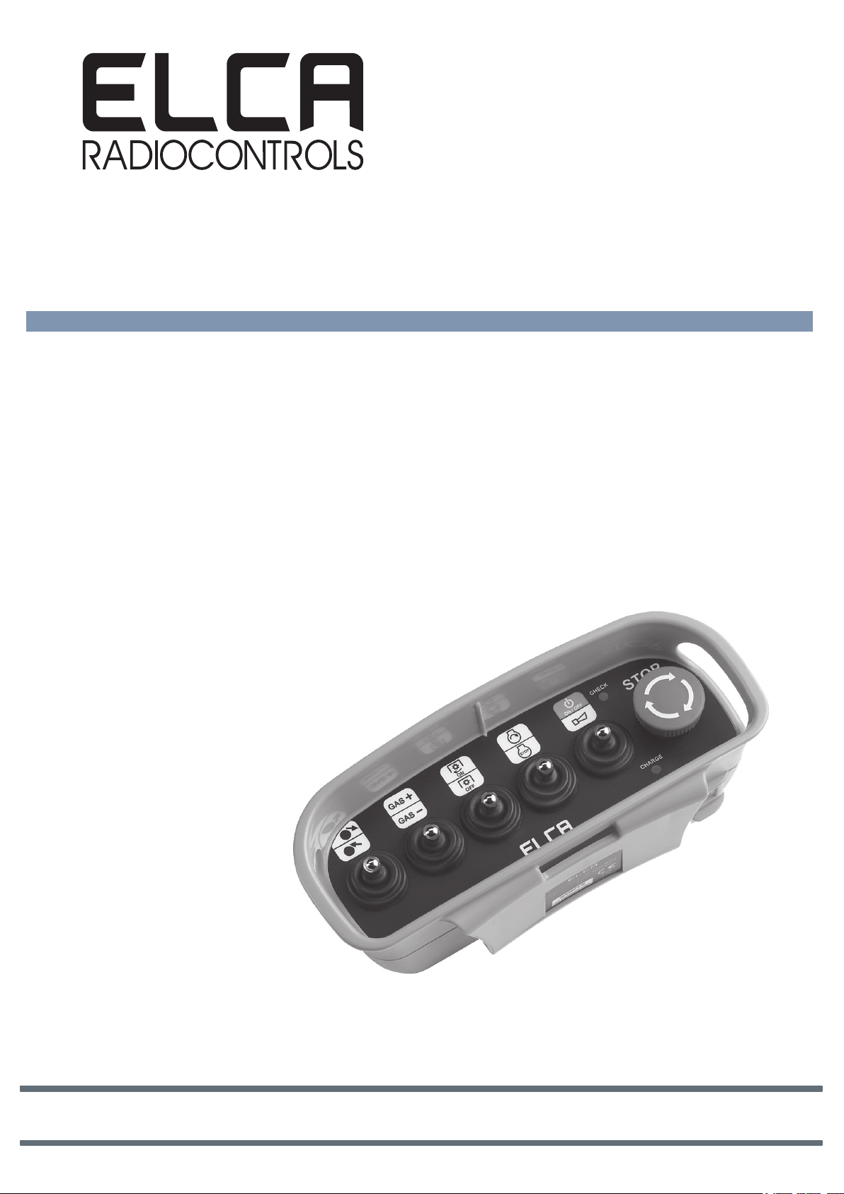
2.4 TRANSMITTING UNIT AT MITO-VETTA-915
T9 T10
T4
T3 T2
T7
T5
T11
T12
ON / OFF
T8
CHECK
CHARGE
Check light
STOP
TA02
Charge light
T1
GENERAL FEATURES.
• Battery charge indication.
When the battery is charged, the Check light blinks quickly (1 ash per second).
When battery charge is close to the limit under which safe command transmission is not ensured, the Check light will
blink more slowly than usual (approximately 1 ash every 2 seconds) for approximately 10 minutes before the transmitter
switches off. The transmitter will not switch on as long as battery charge is not suf cient to ensure safe command
transmission. Keeping the battery charges helps preserve its life cycles.
• Battery charging status indication.
When connecting the charging system the blue light on the transmitter will light to indicate that charging has began. When
the Charge light turn off will indicates that the charging has been completed or aborted. (See section 4.1)
•Continuous Transmission mode with Start/Stop option.
Assigns Start-on- rst-pulse function to command T12, activates radio transmission and Stop on second pulse, and then
deactivates receiver.
When the transmitter is active, the T1 command (Stop push button) immediately shuts down all active commands and
then disconnects power to the transmitter.
Transmission may also terminate automatically after 3 or 10 minutes of system inactivity, depending on preset autoshutdown time (see Paragraph 3.3).
• Acknowledged command transmission.
Radio transmission is activated when the Start command is given and remains active only if the transmitter can receive
the acknowledge signal sent by the receiver. This function ensures that transmitted command reaches the receiver, as
transmitting and receiving units establish permanent communication.
• Automatic working frequency change.
Radio transmission always occurs at low-noise frequencies thanks to the LBT (Listen Before Transmit) technology.
This technology enables the system to check that a frequency is free from noise or clear before using it. Whenever
communication between transmitter and receiver fails, the system will automatically and seamlessly change working
frequency.
• Electronic key.
A sequence of three commands (Pin Code) to unlock the Start command (T12) can be programmed.
• Latching control.
Each command - except the T12 and T1 commands - can be set to latching mode. A latched command will remain active
after the rst pulse until the next pulse is given or until the transmitter is switched off.
Note:
The programmable functions may be blocked in radio remote controls with special features dedicated exclusively to
particular applications or kinds of machines.
Note 1:
Features of customised models may differ from those outlined in this manual. Any such particular features are described
in annexed documents.
- Page 4 -

ENG man MITO-VETTA 915 00 Radio Remote Control System MITO-VETTA-915
2.5 RECEIVING UNIT AR MITO-MINI-915
EXTERNAL
CONNETTORE
ANTENNA
LEARN LIGHT
SPIA LEARN
STATUS LIGHT
SPIA STATUS
POWER LIGHT
SPIA POWER
DIP SWITCH
DIP SWITCH
RADIO MUDULE
MODULO RADIO
RADIO MODULE
MODULO RADIO
ANTENNA
CONNECTOR
ESTERNA
TERMINAL BLOCK
MORSETTIERA
RADIO MODULE
SPIA CHECK
CHECK LIGHT
MODULO RADIO
ENGLISH
FUSE ON
FUSIBILE SU
RELAY T1
DIP SWITCH
DIP SWITCH
MOTHER BOARD
SCHEDA BASE
MOTHER BOARD
SCHEDA BASE
M16
OPZIONE
PRESSACAVO
CABLE GLAND
M16
OPTION
M20
PRESSACAVO
CABLE GLAND
M20
OPTION
RELE' T1
GENERAL FEATURES.
• Self-diagnosis.
The system runs a diagnostic test (CHECK light blinks twice per second) during the rst ve seconds after receiver
power-on.
CHECK light blinks once every 2 seconds SYSTEM OK.
CHECK light on steady SYSTEM FAILURE.
• Output commands.
Relay T1 (Stop) is active when the radio connection between transmitter and receiver is active. Relay T1 (Stop) is
protected by fuse F1 (6.3A).
Relay T12 (Alarm) is activated at the press of T8 (Alarm) on the transmitter.
• Indicator lights.
POWER LIGHT indicates the system is powered on.
STATUS LIGHT blinks once per second to indicate that radio connection is active.
LEARN LIGHT provides indications when in programming mode.
• External antenna option.
Bring the external antenna cable to cable gland M16 which you will have prepared previously. Connect the external
antenna to the connector on the radio module; do not force the connection. Tighten the cable gland on the largest
diameter cable only.
• Terminal block and wiring.
Maximum useful cross-section area 2.5 sq mm. For wiring connections, follow the mother board layout and the wiring
examples provided in ANNEX and annexed documents.
- Page 5 -

ENG man MITO-VETTA 915 00 Radio Remote Control System MITO-VETTA-915
2.6 STORING ACCESS CODES
In order to associate a transmitter to receiver, the transmitter access code needs to be stored in the receiver memory. The
access code is a unique code set at the factory that prevents the receiver installed on the machinery from responding to
any unauthorised transmitters. When several transmitters are registered in a receiver’s memory, the receiver will handle
transmitters on a rst-come-rst-served basis and the current transmitter will have exclusive access to the receiver until
transmission is terminated. Up to 20 access codes can be stored.
Learn mode:
The learn mode allows you to associate one or more new transmitters to the receiver
REMOVE POWER FROM
IS RECEIVER
POWERED ON?
YES
RECEIVER
NO
OPEN RECEIVER COVER AND NOTE SETTINGS OF MODULE
SET DIP 1,2,3 TO OFF AND DIP 4 TO ON. POWER ON
IS STATUS LIGHT
ON STEADY ?
MICROSWITCHES
RECEIVER.
NO
CHECK RECEIVER POWER
SUPPLY AND SETTING OF DIP 4
AND REPEAT PROCEDURE
YES
ACTIVATE TRANSMITTER TO BE MATCHED TO RECEIVER
KEEP ANY OTHER TRANSMITTERS SWITCHED OFF.
DID LEARN LIGHT
BLINK 5 TIMES?
YES
CODE STORED
(COMMAND T12).
NO
IS LEARN LIGHT
BLINKING
QUICKLY?
NO
WARNING! LEARN ERROR (FAILED
TO RECEIVE COMMAND TX OR
CODE ALREADY STORED) REPEAT
PROCEDURE
YES
LEARN ERROR (for instance ATTEMPT TO
DELETE IDENTIFIER CODES AND THEN
STORE REQUIRED ACCESS CODES.
WARNING!
STORE CODE #21).
YES
ANY OTHER AT /
CODE TO
MATCH/STORE?
NO
SET DIP 4 TO OFF
DID STATUS LIGHT
YES
CODE STORED
REMOVE POWER SUPPLY FROM RECEIVER
AND SET MICROSWITCHES
- Page 6 -
GO OUT ?
NO
ENTERED CODE WAS
NOT STORED: REPEAT
WARNING!
PROCEDURE.

ENG man MITO-VETTA 915 00 Radio Remote Control System MITO-VETTA-915
NO
REMOVE POWER FROM
RECEIVER
YES
OPEN RECEIVER COVER AND NOTE SETTINGS OF MODULE
MICROSWITCHES
SET DIP 1,2,3 TO OFF AND DIP 4 TO ON. POWER ON RECEIVER.
IS STATUS LIGHT
ON STEADY?
YES
NO
REMOVE POWER SUPPLY FROM RECEIVER AND SET
MICROSWITCHES.
START LEARN PROCESS.
SET DIP 1 TO ON.
IS LEARN LIGHT
ON STEADY?
YES
SET DIP 1 TO OFF.
DID LEARN
LIGHT BLINK 5
TIMES?
YES
SET DIP 4 TO OFF.
DID STATUS
LIGHT BLINK 9
TIMES?
YES
NO
ALL CODES WERE DELETED
WARNING!
DELETION FAILED: REPEAT
PROCEDURE.
IS RECEIVER
POWERED ON?
CHECK RECEIVER POWER
SUPPLY AND SETTING OF DIP 4
AND REPEAT PROCEDURE
NO
NO
Delete mode:
The delete mode removes from the receiver memory ALL access codes of transmitters associated.
ENGLISH
1
Note
unless all available access codes have been used.
Note2: If no access codes are stored in the receiver, the STATUS light blinks 8 times quickly, blinks once slowly, stays off
for 3-4 seconds and then repeats the sequence.
: If a transmitter becomes unserviceable and needs to be replaced, there is no need to delete existing access codes
- Page 7 -

ENG man MITO-VETTA 915 00 Radio Remote Control System MITO-VETTA-915
2.7 INFORMATION FOR MAINTENANCE
Please remember that the receiving unit should be disconnected from power supply and the transmitting unit should be
powered off during maintenance procedures.
The Radio Remote Control System requires minimal maintenance, however, following these few simple tips will help
keep it in good working order.
TRANSMITTING UNIT
Periodically
- clean unit with a brush and wet cloth; avoid using alcohol, solvents or detergents
- ensure the battery charge contacts are clean
- check housing and rubber parts for damage
In addition, DO NOT:
- expose unit to jets of water or heavy rain
- leave unit exposed to sun radiation
- clean unit with jets of water or blow with compressed air
- immerse in water
- Before storing the system away for long periods, fully charge the battery
RECEIVING UNIT
Periodically
- clean unit with a brush and wet cloth; avoid using alcohol, solvents or detergents;
- check housing and rubber parts for damage.
- check any connectors and/or cable glands for proper tightening.
In addition, DO NOT:
- clean unit with jets of water or blow with compressed air.
2.8 INFORMATION FOR THE PROPER INSTALLATION OF THE RADIO
REMOTE CONTROL SYSTEM
System must be installed and serviced by qualied and trained personnel.
Proper installation of the radio remote control is critical to ensuring proper operation and ease of maintenance.
Following are a few recommendations to be followed before and after installation:
- Perform a careful risk analysis to determine whether the machine is suitable for working in conjunction with a radio
remote control and identify any residual risks.The manufacturer of the machine and / or the installer of radio remote
control is responsible for this analysis. The ELCA Company can not be held responsible for the operation of its system
on applications where the risk analysis was not carried out properly.
- Be aware that in case of interruption of the radio link for active stop, auto power off, low battery, power failure of the
receiver, radio range exceeded, interference, etc.. all the outputs of the receiver are turned off and it is no longer
possible to control the equipment until a further restart of the radio remote control. Carefully consider whether this can
be a danger.
- Where it is not already provided, it is necessary to limit the maximum current on the power supply circuit to 10 Amps
- In case on the relay contacts you use dangerous voltages, higher than 42.4 Volt AC or higher than 60 Volt DC, you
need to consider also power supply circuit as connected to dangerous voltages. In this case it is necessary to provide
a power circuit dedicated to the feeding of the receiver with suitable connections as regards the exhisting dangerous
voltage.
- In case of dangerous voltages inside the receiver, it is not allowed to use the external antenna.
- To obtain the maximum range, install the receiving unit between 2 and 10 metres above the ground and where there
are no obstacles between transmitter and receiver;
- install the receiving unit housing within easy reach to ensure safe access by repair or maintenance technicians;
- use multi-pin connectors to connect receiver to machine so as to facilitate replacement in the event of a failure;
- the place selected for receiving unit installation should be free from vibration: where this is not possible, use vibration
dampers;
- Page 8 -
 Loading...