

EL BJORN A155F, A155HW User Instructions

User instructions
WARNING!
400V
VARNING!
FÅR EJ ÖVERTÄCKAS
OBS!
BYT FILTER
REGELBUNDET
Drying room dehumidier
A155F/A155HW

Table of contents ........................................................ 2
Introduction ........................................................ 3
Technical data ........................................................ 3
Safety instructions ........................................................ 4
Description ....................................................................... 5-9
Installation ....................................................................... 10-13
Drying ....................................................................... 14-15
Maintenance ....................................................................... 16-17
Spare parts/accessories ........................................................ 18
TABLE OF CONTENTS
- 2 -

4
INTRODUCTION
TECHNICAL DATA
- 3 -
Technical data, dehumidier
Width: 470 mm
Height: 1498 mm
Depth: 370 mm
Noise level: 66dB
Weight: 70 kg
Electrical connection: 3N~400V
Fuse: 10 A slow
Rated power (A 155F): 5400W
Rated power (A 155HW): 1200W
Auxiliary heating: 3990W
Operating range, temp.: 15-35ºC
Operating range, RH: 35-99%
Dehumidication capacity: Max. 3 l/h
Refrigerant, type: R134a
Refrigerant, amount: 870g
The A 155 dehumidier is designed for the high
capacity drying of laundry in large drying rooms, for
example in apartment / multi occupancy buildings
or on site Portacabins. An optional pipe system
for hanging laundry on can be ordered with the
dehumidier. See web site for more information
This instruction manual covers the free-blowing
dehumidiers A 155F (standard electric) and the
155HW (hot water), model designed for district
heating.
The manual contains detailed instructions for use,
maintenance and inspection of the dehumidier with
or without a pipe system. It includes instructions for
insuring maximum safety and information on the
design and use of the safety features.
NOTE: All persons using or repairing the
dehumidier should carefully read the section
on safety.
This manual contains instructions on use of the
product and maintenance that can be carried out by
the operator.
More detailed servicing or troubleshooting may only
be performed by the manufacturer’s service staff or
representative.
The user instructions describe all the necessary safety
features.. The rst thing the user should do following
delivery, is to read the instruction manual carefully.
This should be done before connecting to the
electricity supply.
The manufacturer reserves the right to make
modications.
Various symbols and warning signs are shown in
this manual and displayed on the dehumidier.
They are listed on the next page.
If any of the warning signs on the dehumidier
are damaged in any way, a new one must be
ordered and attached immediately to ensure
maximum safety during use of the dehumidier.
The dehumidier may only be used for the
applications described in this user manual.
The manufacturer reserves the right to make any
modications.
5
SAFETY INSTRUCTIONS
- 4 -
Warning signs on the dehumidier
Read the instruction manual carefully
before using the dehumidier.
Warning of high voltage if the hatch is
opened before the power supply to the
dehumidier has been turned off.
The manufacturer’s guarantee that this
product meets the safety provisions of
the Low Voltage Directive.
Safety during installation
Electrical connection of the dehumidier and its peripheral
equipment should be carried out by a qualied electrician.
Safety during use
The dehumidier’s air intake and air outlet must never
be covered during operation. It is strictly forbidden
to remove the protective hoods or cover plates during
operation.
Safety during maintenance
The power supply to the machine must be cut off
before performing maintenance on the dehumidier.
This can be done by pulling the connector out of
the power socket, or by breaking the current with the
circuit breaker.
All maintenance of the electrical system must be
performed by a qualied electrician.
All maintenance of the refrigeration system must be
performed by a qualied refrigeration technician.
When cleaning the condenser and evaporator, use
gloves to avoid cutting injuries.
Caution! and Note:
The following boxes are shown in this instruction
manual where appropriate.
CAUTION!
These boxes warn of injury or
damage to people or objects.
The caution boxes are shown in front
of the procedure they refer to.
NOTE:
These boxes contain special
instructions and information on how
to make specic procedures easier.
The lter should be
replaced 1–2 times per
year. Also see under
“Maintenance”.
The dehumidier’s air
intake and air outlet
must never be covered.
Warning signs in these user instructions
Read the instruction manual carefully
before using the dehumidier.
Caution! The dehumidier may be
dangerous. Careless or incorrect use
could result in serious or even fatal
injury.
The manufacturer’s guarantee that this
product meets the safety provisions of
the Low Voltage Directive.
VARNING!
400V
• The product may not be used by persons (including
children) with physical or mental disabilities,
unless they have received information or instruction
on safe use of the product from a person with
responsibility for their safety.
• However, the product is suitable for use in
environments where there are persons (including
children) with physical or mental disabilities or
impaired judgement.
• If children have access to the product, they must be
instructed not to use the product for playing with.
1-2 times / year
604503

DESCRIPTION
- 5 -
WARNING!
400V
VARNING!
FÅR EJ ÖVERTÄCKAS
OBS!
BYT FILTER
REGELBUNDET
1
2
16
AEV
9
LP
M2
10
12
K2
K1
X
S1
GT3
GT2
GT5
1 Ceiling mounting with suspension bars.
2 Side bar
3 Drying pipes
4 Base pipe
5 End plate
6 Inner telescopic tube
7 Outer telescopic tube
8 Anti-tip device
9 Drain water connection, for copper pipe Ø15 mm
10 Adjustable foot
12 Type plate
13 Sticker “Replace lter regularly”
14 Filter cassette (inside door)
15 Sticker “Do not cover”
16 Hanger (accessory)
B1 Overcurrent relay
AEV Evaporator. (Also see next page).
E Auxiliary heating 3990 W. (1330x3)(See next page or
water condenser A 155HW
FT Dryer lter. (See next page).
GT1 Thermostat for control of heating coil
GT2 Overheating protector, manual reset (x 2).
GT3 Overheating protector, automatic reset GT4
Thermocontact switch in fan (not shown).
GT5 Low pressure control
GT6 Overload protection device, compressor
GT7 Overload protection device, compressor
K1 Contactor for fan
K2 Contactor for compressor
K3 Contactor for heating coil
KD Capacitor. (See next page).
M1 Fan. (See next page).
M2 Compressor
S1 Timer, 2 options
X Terminal block
SD Capillary tube, throttle (see next page).
LP Low pressure control
GT1
B1
K3
3
5
4
6
7
8
15
13
14
Fig 1. A 155 with pipe system
Fig 1. A 155 with pipe system
GT6/GT7
DESCRIPTION
- 6 -
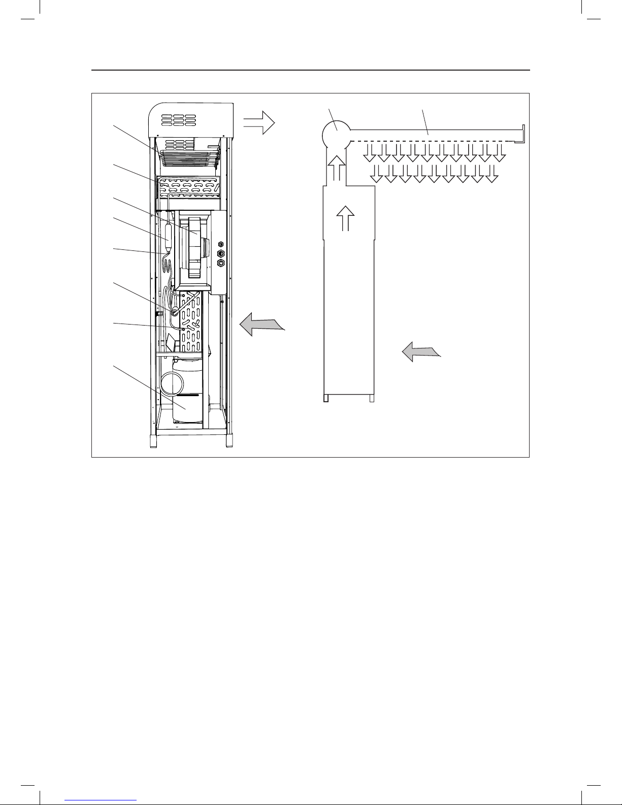
Function
Dehumidier A 155
The A 155 is a condensation dehumidier, and is
based on the principle that air moisture condenses on
cold surfaces.
The cold surfaces are created on the evaporator
(AEV) when the compressor (M2) transfers heat from
the evaporator to the condenser (KD).
The dehumidier is equipped with a fan (M1) that
transports the air through the dehumidier.
The air rst passes through the evaporator (AEV),
where the moisture condenses and is deposited on the
evaporator.
The condensate collects in a trough located
underneath the evaporator, is transported away.
The air then passes through the fan (M1) and the
condenser (KD). In the condenser, the air is warmed
up and the condenser is simultaneously cooled.
After this, the air can be heated by the auxiliary
heating system (E) before being released from the
dehumidier.
Pipe system
The pipe system has two functions: it distributes the
air and is used for hanging washing on. The diameter
of the drying pipes is(Ø60 mm) (3) prevents clothes
from creasing whilst drying.
Dry air from the dehumidier is blown into the pipe
system and distributed to the drying pipes (3) via the
base pipe (4).
Dry air is blown downwards through holes in the
drying pipes, and is distributed between the items of
laundry.
This dries the laundry evenly, even in the places that
are least exposed.
All tubes are made of extruded, anodised aluminium,
making them highly durable and corrosion-resistant.
E
KD
M1
FT
SD
A
AEV
M2
Moist air
4 3
Moist air
Dry air
Dry air
Fig 3. A 155F (left) and A 155 with pipe system
 Loading...