

Elba PXDO 906 DF, PBKDO 906 DF Instructions For Use - Installation Advice
TWIN OVEN
DUAL FUEL
COOKER
PXDO 906 DF
PBKDO 906 DF
GB
Instructions for use - Installation advice
KEEP IN A SAFE PLACE

2
Read the instructions carefully before installing and using the appliance.
CAUTION: this apparatus must only be installed in a permanently ventilated room in
compliance with the applicable regulations.
Dear Customer,
Thank you for having purchased and
given your preference to our product.
The safety precautions and
recommendations reported below are
for your own safety and that of others.
They will also provide a means by
which to make full use of the features
offered by your appliance.
Please preserve this booklet
carefully. It may be useful in future,
either to yourself or to others in the
event that doubts should arise relating
to its operation.
This appliance must be used only
for the task it has explicitly been
designed for, that is for cooking
foodstuffs. Any other form of usage
is to be considered as inappropriate
and therefore dangerous.
The manufacturer declines all
responsibility in the event of damage
caused by improper, incorrect or
illogical use of the appliance.
IMPORTANT INSTRUCTIONS AND
ADVICE FOR THE USE OF
ELECTRICAL APPLIANCES
The use of any electrical appliance
requires the compliance with some basic
rules, namely:
– do not touch the appliance with wet or
damp hands (or feet)
– do not use the appliance whilst in bare
feet
– do not allow the appliance to be
operated by children or unqualified
persons without supervision.
The manufacturer cannot be deemed
responsible for damages caused by
wrong or incorrect use.
AFTER SALES SERVICE
If you require After Sales Service contact
the MASTERCARE Domestic Appliance
Helpline Telephone 08701 565550.
This cooker has been designed, constructed and marketed in compliance with:
- safety requirements of EEC Directive “Gas” 90/396;
- safety requirements of EEC Directive “Low voltage” 73/23;
- protection requirements of EEC Directive “EMC” 89/336;
- requirements of EEC Directive 93/68.
Important:
This appliance is designed and manufactured solely for the cooking of domestic
(household) food and is not suitable for any non domestic application and therefore
should not be used in a commercial environment.
The appliance guarantee will be void if the appliance is used within a non domestic
environment i.e. a semi commercial, commercial or communal environment.

3
FIRST USE THE OVEN
It is advised to follow these instructions:
– Clean the interior of the oven with
cloth soaked in water and detergent
(neutral) then dry carefully.
– Furnish the interior of the oven by
placing the wire racks as described
at chapter “Cleaning and
maintenance”.
– Insert shelves and tray.
– Empty the oven and close the door.
Heat the oven at the maximum
temperature setting for around two
hours to eliminate the odour of
grease and fumes from the
manufacturing process. Make sure
that the kitchen is well ventilated and
do not remain in the room during this
process.
IMPORTANT PRECAUTIONS
AND RECOMMENDATIONS
After having unpacked the appliance,
check to ensure that it is not damaged
and that the oven doors close correctly.
In case of doubt, do not use it and
consult your supplier or a professionally
qualified technician.
Packing elements (i.e. plastic bags,
polystyrene foam, nails, packing straps,
etc.) should not be left around within
easy reach of children, as these may
cause serious injuries.
● ATTENTION: Model PXDO 906 DF
Please peel plastic cover of both
sides and front before use.
● Do not attempt to modify the technical
characteristics of the appliance as
this may cause danger to users.
● Do not carry out cleaning or
maintenance operations on the
appliance without having previously
disconnected it from the electric
power supply.
● If you should decide not to use this
appliance any longer (or decide to
substitute another model), before
disposing of it, it is recommended that
it be made inoperative in an
appropriate manner in accordance to
health and environmental protection
regulations, ensuring in particular that
all potentially hazardous parts be
made harmless, especially in relation
to children who could play with
unused appliances.
● After use, ensure that the knobs are
in off position.
● Do not allow children or other
unqualified people to use the
appliance without your supervision.
● During and after use of the cooker,
certain parts will become very hot. Do
not touch hot parts.
● Keep children away from the cooker
when it is in use.
● Some appliances are supplied with a
protective film on steel and aluminium
parts. This film must be removed
before using the appliance.
● Fire risk! Do not store flammable
material in the oven and in the
storage compartment.
● Make sure that electrical cables
connecting other appliances in the
proximity of the cooker cannot come
into contact with the hob or become
entrapped in the oven doors.
● Do not line the oven walls with
aluminium foil. Do not place baking
trays or the drip tray on the base of
the oven chamber.
● The manufacturer declines all liability
for injury to persons or damage to
property caused by incorrect or
improper use of the appliance.
● The various components of the
appliance are recyclable. Dispose of
them in accordance with the
regulations in force in your country. If
the appliance is to be scrapped,
remove the power cord.

4
1 - COOKING HOB
Fig. 1.1
2345
6
1
COOKING HOB
1. Double-ring burner (PB) 3,45 kW
2. Semi-rapid burner (SR) 1,90 kW
3. Rapid burner (R2) 2,95 kW
4. Auxiliary burner (A) 1,00 kW
5. Semi-rapid burner (SR) 1,90 kW
6. Auxiliary burner (A) 1,00 kW
5
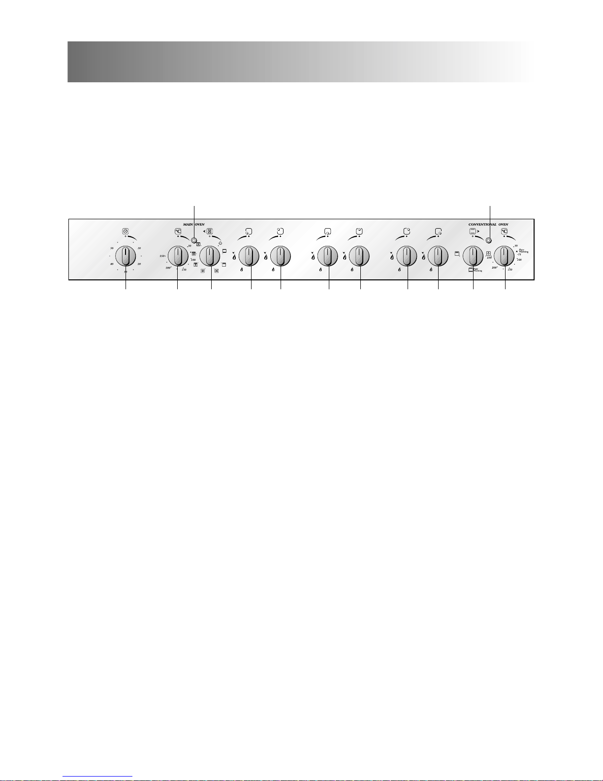
2 - CONTROL PANEL
Fig. 2.1
98 65 10321117
1312
CONTROL PANEL - Controls description
1. Front right burner control knob
2. Rear right burner control knob
3. Rear central burner control knob
4. Front central burner control knob
5. Rear left burner control knob
6. Front left burner control knob
7. Multifunction main oven switch knob
8. Multifunction main oven thermostat knob
9. Minute counter (60 minutes)
10. Conventional oven thermostat knob
11. Conventional oven switch knob
Pilot lamps:
12. Main oven thermostat indicator light
13. Conventional oven thermostat indicator light
4
6
3 - USE OF COOKING HOB
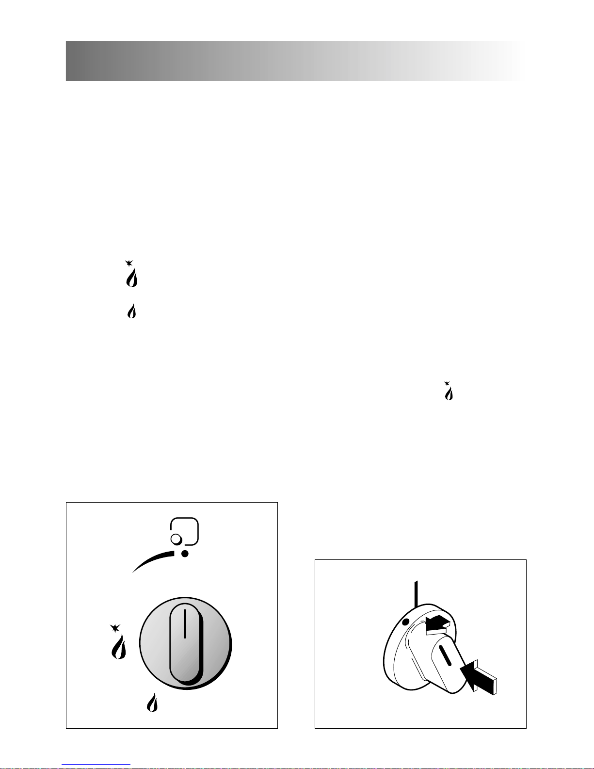
GAS BURNERS
Each burner is controlled by a gas tap
assuring the opening and the closing of
the gas supply.
Make the lever of the knob match with
the indicator on the control panel to
obtain:
– symbol
● : off
– symbol : full on (nominal rate)
– symbol : reduced rate
To reduce the gas flow to minimum,
rotate the knob anti-clockwise to point
the lever towards the small flame
symbol.
Fig. 3.1
The maximum aperture position permits
rapid boiling of liquids, whereas the
minimum aperture position allows slower
warming of food or maintaining boiling
conditions of liquids (simmering).
Other intermediate operating
adjustments can be achieved by
positioning the lever between the
maximum and minimum aperture
positions, and never between the
maximum aperture and off positions.
LIGHTING THE BURNERS
To ignite the burner, the following
instructions are to be followed:
1) Lightly press and turn the knob anticlockwise, and position the knob
indicator to the symbol printed on the
control panel (fig. 3.2).
2) Press the knob to operate the electric
ignition; or, in the case of a mains
failure light the burner with a match or
lighted taper.
3) Adjust the burner according to the
setting required.
Fig. 3.2
7
CHOICE OF THE BURNER
On the control panel, near every knob,
there is a diagram that indicates which
burner is controlled by that knob.
The suitable burner must be chosen
according to the diameter and the
capacity used.
As an indication, the burners and the
pots must be used in the following way:
It is important that the diameter of the
pot be suitable to the potentiality of the
burner so as not to compromise the high
output of the burners and therefore
energy waste.
A small pot on a large burner does not
give you a boiling point in a shorter
amount of time since the capacity of
heat absorption of a liquid mass
depends on the volume and the surface
of the pot.
Fig. 3.3a
BURNERS POT DIAMETER
Auxiliary 12 - 16 cm
Semi-rapid 16 - 22 cm
Rapid 24 - 24 cm
Double-ring up to 30 cm
do not use pans with concave or convex bases
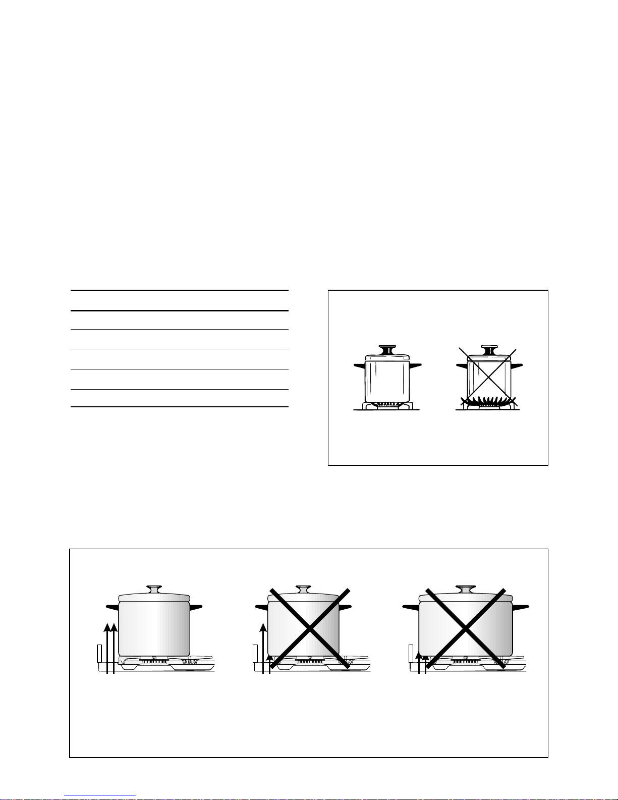
AIR FLOW
(cooling fan)
AIR FLOW
(cooling fan)
AIR FLOW
(cooling fan)
CORRECT USE OF RAPID BURNER
Fig. 3.3b
8
Fig. 3.4b
Fig. 3.4a
WRONG
CORRECT
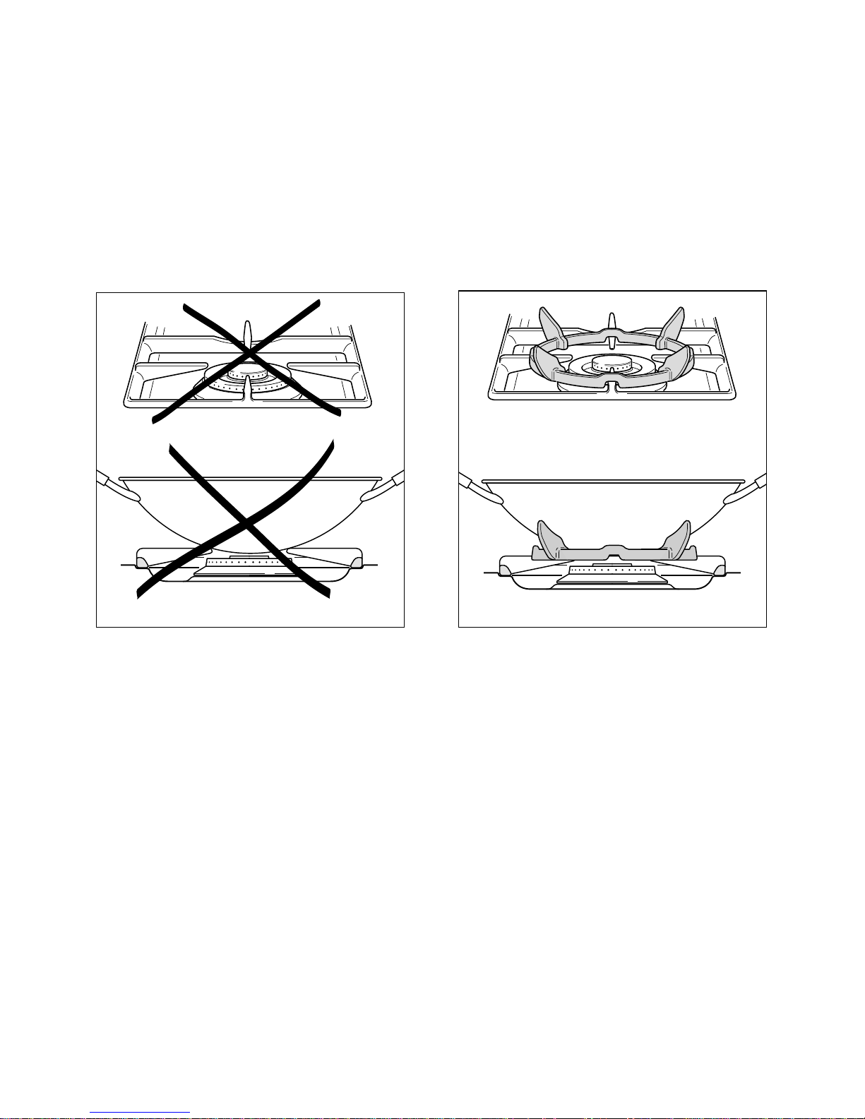
CORRECT USE OF DOUBLE-RING BURNER
The flat-bottomed pans are to be placed directly onto the pan-support.
When using a WOK you need to place the supplied stand in the burner to avoid any faulty
operation of the double-ring burner (Fig. 3.4a - 3.4b).
9
Attention: the oven door
becomes very hot during operation.
Keep children away.
GENERAL FEATURES
As its name indicates, this is an oven
that presents particular features from an
operational point of view.
In fact, it is possible to insert 7 different
programs to satisfy every cooking need.
The 7 positions, thermostatically controlled, are obtained by 4 heating elements which are:
– Bottom element 1400 W
– Top element 1000 W
– Grill element 2000 W
– Circular element 2500 W
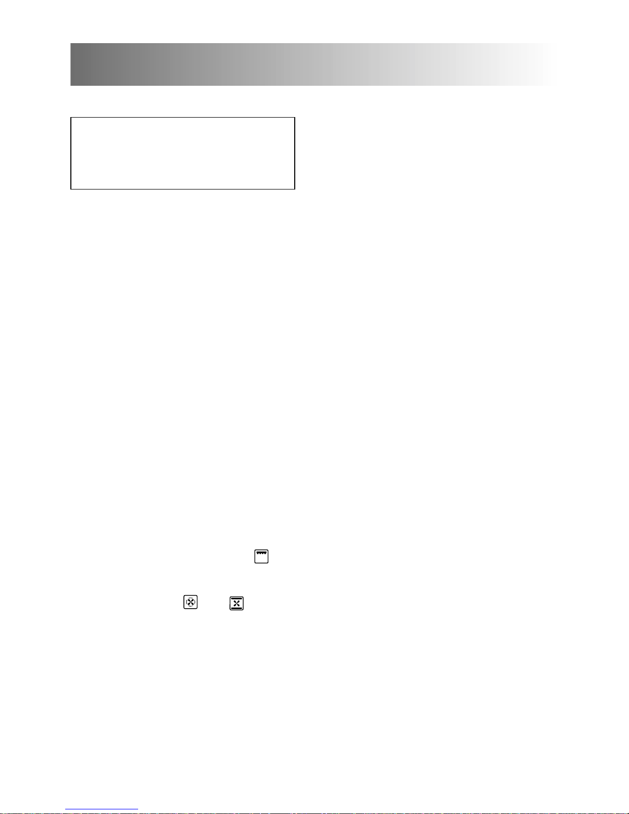
NOTE:
Upon first use, it is advisable to operate the
oven for 30 minutes in the position and
for another 30 minutes at the maximum
temperature (thermostat knob on position
250) in the positions
and
, to eliminate possible traces of grease on the heating elements.
Clean the oven and accessories with warm
water and washing-up liquid.
WARNING:
The door is hot, use the handle.
OPERATING PRINCIPLES
Heating and cooking in the MULTIFUNCTION oven are obtained in the following ways:
a. by normal convection
The heat is produced by the upper and
lower heating elements.
b. by forced convection
A fan sucks in the air contained in the
oven muffle, which sends it through
the circular heating element and then
sends it back through the muffle.
Before the hot air is sucked back
again by the fan to repeat the
described cycle, it envelops the food in
the oven, provoking a complete and
rapid cooking.
It is possible to cook several dishes
simultaneously.
c. by semi-forced convection
The heat produced by the upper and
lower heating elements is distributed
throughout the oven by the fan.
d. by radiation
The heat is irradiated by the infra red
grill element.
e. by radiation and ventilation
The irradiated heat from the infra red
grill element is distributed throughout
the oven by the fan.
4 - MULTI-FUNCTION MAIN OVEN

10
Fig. 4.1 Fig. 4.2
FUNCTION SELECTOR KNOB
Rotate the knob clockwise to set the
oven for one of the following functions:
OVEN LIGHT
By turning the knob onto this setting we
light the oven cavity (15 W).
The oven remains alight while any of the
functions is on.
THERMOSTAT KNOB
To turn on the heating elements of the
oven, set the switch knob on the desired
program and the thermostat knob onto
the desired temperature.
To set the temperature, it is necessary to
make the knob indicator meet the chosen
number.
The elements will turn ON or OFF automatically according to the energy need
which is determined by the thermostat.
TRADITIONAL CONVECTION
COOKING
The upper and lower heating elements
are switched on. The heat is diffused by
natural convection and the temperature
must be regulated between 50° C and
250° C with the thermostat knob.
It is necessary to preheat the oven
before introducing the foods to be
cooked.
RECOMMENDED USE:
For foods which require the same cooking temperature both internally and
externally, i. e. roasts, spare ribs,
meringue, etc.

11
GRILLING
The infra-red heating element is switched
on. The heat is diffused by radiation.
Use with the oven door closed and the
thermostat knob to position 225°C for
max 15 minutes, then to position 175°C.
For correct use see chapter “USE OF THE
GRILL”.
Note: It is recommended that you do not
grill for longer than 30 minutes at any one
time.
Attention: the oven door becomes very
hot during operation. Keep children away.
For correct use see chapter “USE OF
THE GRILL”.
RECOMMENDED USE:
Intense grilling action for cooking with the
broiler; browning, crisping, “au gratin”,
toasting, etc.
DEFROSTING FROZEN FOODS
Only the oven fan is on.
To be used with the thermostat knob on
“●” because the other positions have no
effect. The defrosting is done by simple
ventilation without heat.
RECOMMENDED USE:
To rapidly defrost frozen foods; 1 kilogram requires about one hour.
The defrosting times vary according to
the quantity and type of foods to be
defrosted.
HOT AIR COOKING
The circular element and the fan are on.
The heat is diffused by forced convection
and the temperature must be regulated
between 50° and 250 °C with the thermostat knob.
It is not necessary to preheat the oven.
RECOMMENDED USE:
For foods that must be well done on the
outside and tender or rare on the inside,
i. e. lasagna, lamb, roast beef, whole
fish, etc.
VENTILATED GRILL COOKING
The infra-red ray grill and the fan are on.
The heat is mainly diffused by radiation
and the fan then distributes it throughout
the oven.
The temperature must be regulated between
50° and 175 °C for max 30 minutes, with
the thermostat knob.
Leave to warm up for approximately 5
minutes with the door closed.
It is recommended that you do not
grill for longer than 30 minutes at any
one time.
Attention: the oven door becomes
very hot during operation.
Keep children away.
For correct use see chapter “GRILLING
AND “AU GRATIN”.
RECOMMENDED USE:
For grill cooking when a fast outside
browning is necessary to keep the juices
in, i. e. veal steak, steak, hamburger,
etc.
 Loading...