

Page 1
55550000xxxx55550000ccccooooooookkkkeeeerrrrss
ss
EC 530
EC 560
88886666xxxx55550000 ccccooooooookkkkeeeerrrrss
ss
EC 830
EC 832
EC 860
EC 861
EC 862
EC 960
EC 961
EC 930
Instruction for the use
Installation advice
Page 2

2
Dear Customer,
We thank you very much for choosing our
products.
The instructions and advice included in
this booklet are given to safeguard your
safety and to use this appliance correctly.
Be so kind as to keep this booklet.
It will be useful to clear any doubt
concerning its operation.
This appliance must be only assigned to
the use for which it has been realized,
that is for cooking food.
Any other use has to be considered
incorrect and therefore dangerous.
The manufacturer declines any liability
for damages caused by wrong, incorrect
or irrational use of the appliance.
FIRST USE THE OVEN
It is advised to follow these instructions:
– Clean the interior of the oven with
cloth soaked in water and detergent
(neutral), then dry carefully.
– Insert shelves and tray.
– Switch on the empty oven on max
to eliminate grease tracks from the
heating elements.
IMPORTANT INSTRUCTIONS AND
ADVICE FOR THE USE OF
ELECTRICAL APPLIANCES
The use of any electrical appliance
requires the compliance with some basic
rules, namely:
– do not touch the appliance with wet or
damp hands (or feet)
– do not use the appliance bare feet
– do not allow the appliace to be oper-
ated by children or disabled without
overseeing.
The manufacturer cannot be deemed
responsible for damages caused by
wrong or incorrect use.
USEFUL HINTS
After removing the appliance from its
packing, make sure of its integrity.
In case of doubt, please apply to your
supplier or to a qualified engineer.
The packing materials (plastic bags,
polyfoam, nails, metal strips etc.) must
be moved away from the reach of the
children as potential sources of danger.
– Do not attempt to alter the technical
features of the appliance as this may
result very dangerous.
– Do not carry out any operation of
cleaning or maintenance without prior
disconnection of the appliance from
the electric supply.
– Whenever you decide to get rid of this
appliance (in case of replacement with
a new one), before scrapping it is rec-
ommended to render it inoperative and
harmless in respect of health and
antipollution regulations.
Page 3
3
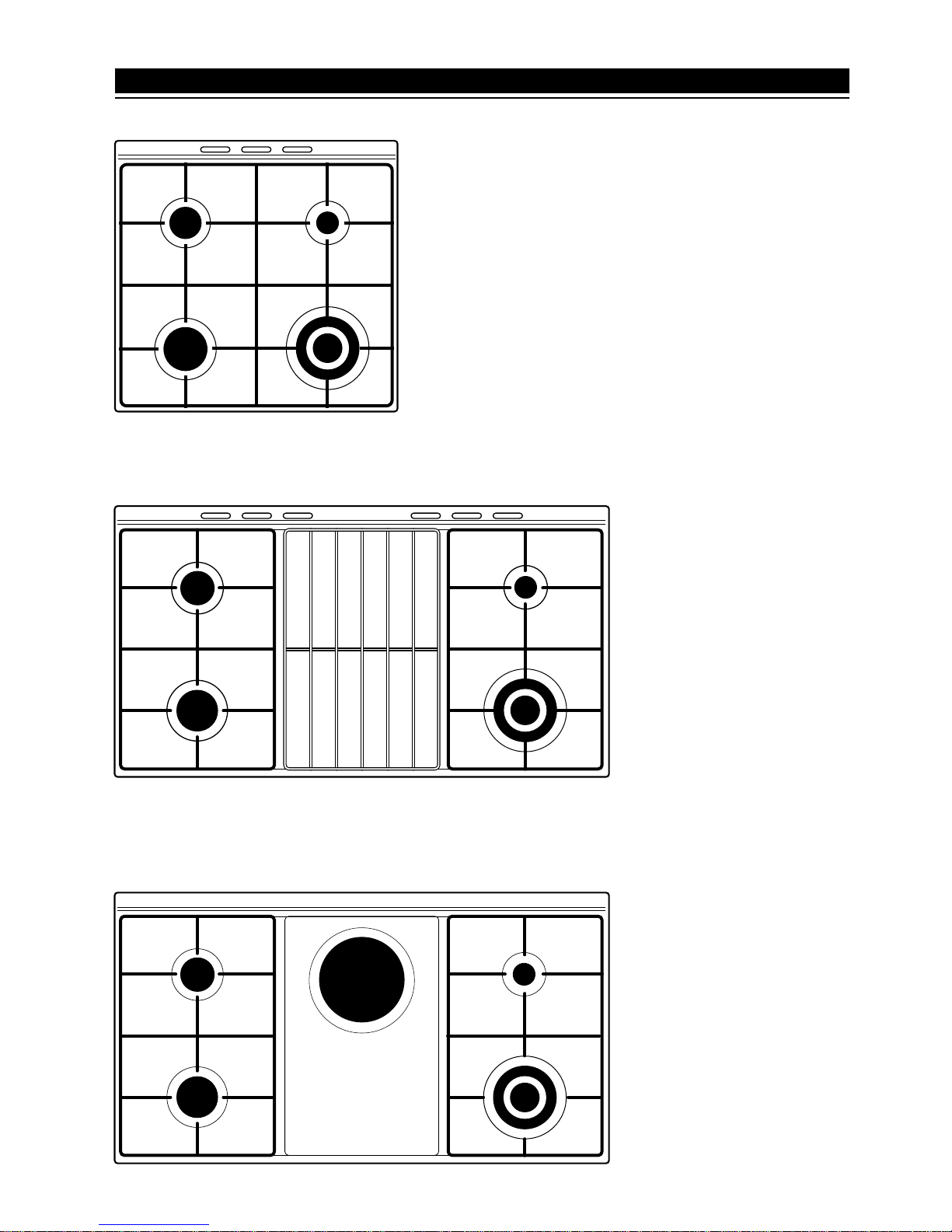
1 - COOKING HOBS
Fig. 1.1
Fig. 1.2
Fig. 1.3
12
3
4
1
2
4
3
12
4
3
5
GAS COOKING HOBS
(Fig. 1.1- 1.2 - 1.3)
GENEREAL FEATURES:
1. Auxiliary burner (A) - 900 W
2. Semi-rapid burner (SR) - 1550 W
3. Rapid burner (R) - 2550 W
4. Double-ring burner (DR) - 3500 W
5. Electrical plate Ø 180 - 1500 W
Page 4
4
51234
Fig. 2.1
Fig. 2.3
51 42 3 9
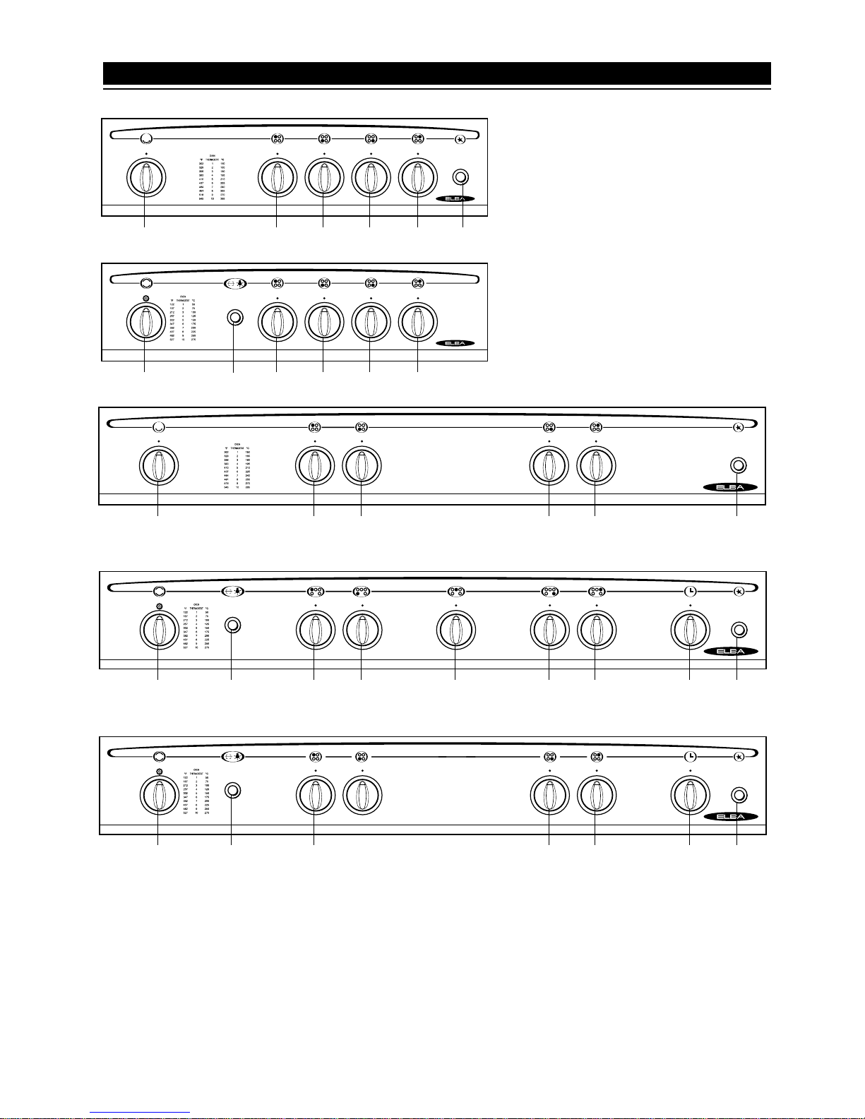
CONTROLS DESCRIPTION
1. Rear left burner control knob
2. Front left burner control knob
3. Front right burner control knob
4. Rear right burner control knob
5. Gas oven control knob
6. Electrical oven control knob
7. Electrical plate control knob (*)
2 - CONTROL PANEL
Fig. 2.4
6
10-11
17482 3 9
8. 60' Timer control knob (*)
9. Gas burner electronic igniter
control button (*)
10. Oven light control button (*)
11. Rotisserie control button (*)
(*): According to the models
6
10-11
1234
Fig. 2.2
9
Fig. 2.5
6
10-11
1 482 3 9
Page 5
5
Each burner is controlled by a gas tap
assuring the opening and the closing of
the gas supply.
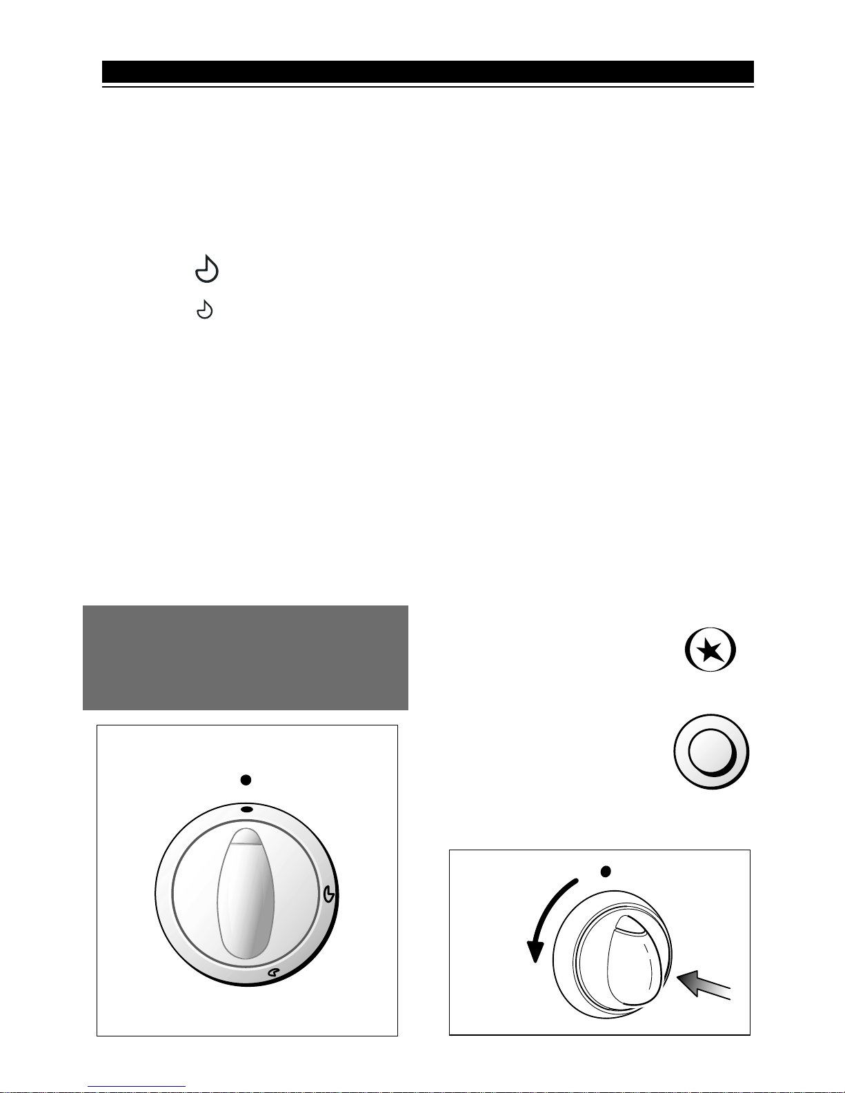
Make the indicator of the knob the symbols printed on the control panel:
- symbol
● : off
- symbol : full on (nominal rate)
- symbol : reduced rate
To open the tap, which allows the flow
of gas to the burner, push the knob and
turn it towards the left.
To turn it off, turn the knob towards the
right up the safety click.
The full-on rate serves to bring foods to
a boil, while the reduced rate consents
the slow heating of foods or the maintenance of the boiling.
All of the positions of the different operations must be chosen between the
maximum and the minimun and never
between the maximum and the turn off
point.
Fig. 3.3
Fig. 3.1
SAFETY VALVES
Some models are equipped with flamefailure device taps/thermostat.
This device allows to stop the gas input
to the tap/thermostat whenever the flame
goes out.
The tap/thermostat opening has to be
done as follows:
1) Turn the knob to full-on setting.
2) Light the gas and keep the knob
pressed in order to allow the flame to
heat the feeler wich activates the
magnet controlling the gas input.
3) After few seconds (20 max) leave the
knob.
Be careful that the feeler be always
clean as the dirt may act as thermic
insulator.
LIGHTING OF TOP BURNERS
The cooker has an automatic ignition
device.
It is enough to push the knob and turn
the tap on the “full-on” position (fig. 3.3)
until the burner lights, then adjust the
flame.
In case of electric ignition,
push the knob and turn the
tap on the “full-on” position.
Then push the switch-button (fig. 3.2) until the burner lights.
Fig. 3.2
3 - USE OF THE HOB BURNERS
In the event of the burner flames being
accidentally extinguished, turn off the
burner control and do not attempt to
re-ignite the burner for at least 1 min.
Page 6
6
Fig. 3.4
CHOICE OF THE BURNER
On the control panel, near every knob,
there is a diagram that indicates which
burner is controlled by that knob.
The suitable burner must be chosen
according to the diameter and the
capacity used.
As an indication, the burners and the
pots must be used in the following way:
It is important that the diameter of the
pot be suitable to the potentiality of the
burner so as not to compromise the high
output of the burners and therefore
energy waste.
A small pot on a large burner does not
give you a boiling point in a shorten
amount of time since the capacity of
heat absorption of a liquid mass
depends on the volume and the surface
of the pot.
BURNERS POT DIAMETER
Auxiliary 12 - 16 cm
Semi-rapid 16 - 20 cm
Rapid 20 - 24 cm
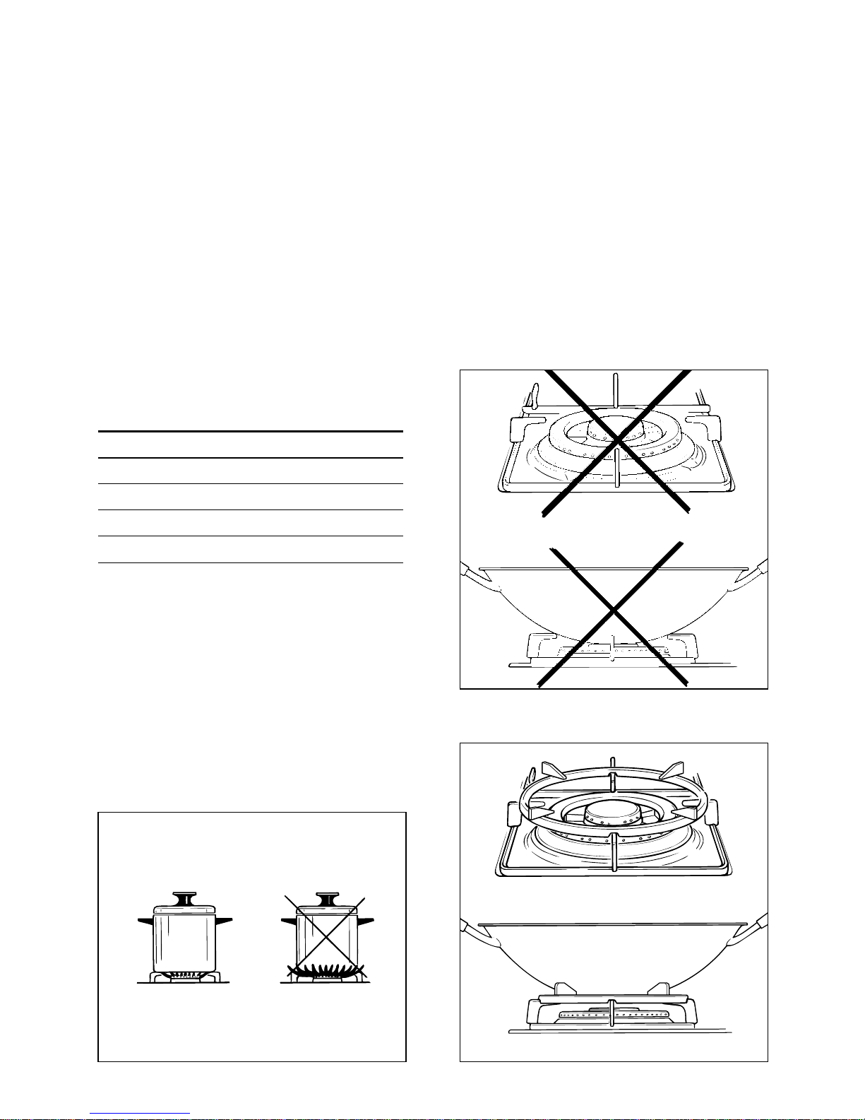
Double-ring wok
Fig.
3.5b
Fig.
3.5a
WRONG
CORRECT
CORRECT USE OF
DOUBLE-RING BURNER
The flat-bottomed pans are to be placed
directly onto the pan-support.
To use the WOK you need to place the
proper stand in order to avoid any faulty
operation of the double-ring burner
(Fig. 3.5)
MODELS WITH BATTERY IGNITION
- If the electronic ignition does not work
make sure that the battery, installed
on the back of the cooker, is not flat
and has been installed correctly (see
the chapter “Battery installation”, page
19).
Page 7
7
0
6
5
4
3
2
1
Fig. 3.6
HOTPLATES
NORMAL HOTPLATES
To switch on the normal hotplate, turn
the knob (Fig. 3.6) onto the desired position; the numbers 1 to 6 indicate the
working positions with the increase of
temperature according to the number.
Once boiling point has been reached,
reduce the input according to the heating intensity desired, keeping in mind
that the plate will continue to heat for 5
minutes after having been turned off.
RAPID HOTPLATES (red dot)
The control knob of the rapid hotplates
is similar to that of a normal plate with
6 working positions (Fig. 3.6).
The features of this plate, which is
equipped with a heat limiter, allow:
– reaching the temperature rapidly
– maximum exploitation of the input with
flat bottom pots
– the limitation of input in the case of
unsuitable pots.
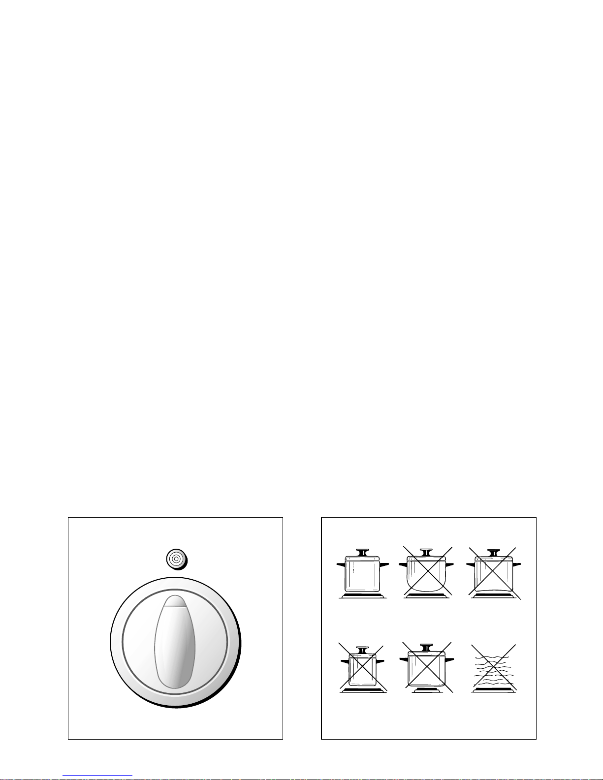
CORRECT USE OF THE
ELECTRICAL PLATES
In using the hotplates you must:
– avoid idle operation (without pots)
– do your best not to pour liquids on the
plates when they are hot
– only use flat bottom pots
– always use pots that completely cover
the surface of the plate.
A lamp signals that the hotplates are
operating.
Fig. 3.7
Page 8
8
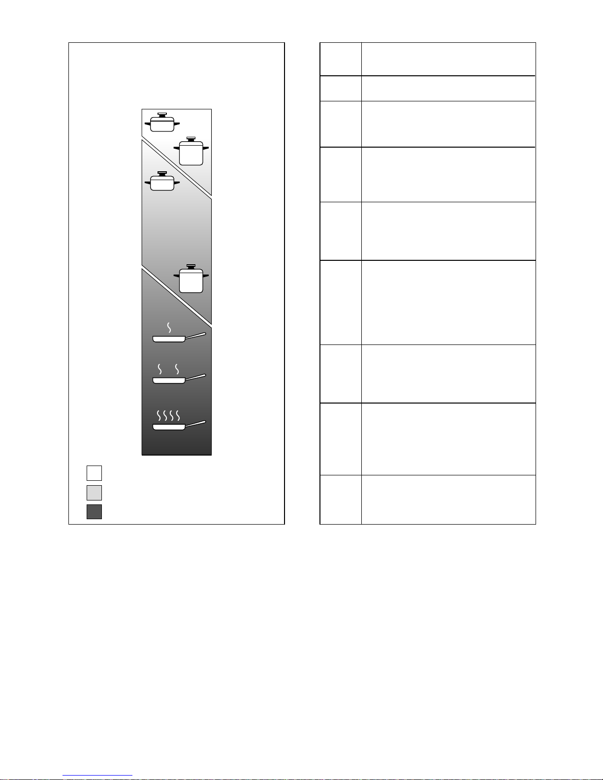
TYPE OF COOKING
Switched OFF
For melting operations
(butter, chocolate).
To maintain food hot and to
heat small quantities of liquid (sauces, eggs).
To heat bigger quantities; to
whip creams and sauces.
(vegetables, fruits, soups).
Slow boiling, i.e.: boiled
meats, spaghetti, soups,
continuations of steam cooking of roasts, stews, potatoes.
For every kind of frying, cutlets, uncovered cooking, i.e.:
risotto.
Browning of meats, roasted
potatoes, fried fish,
omelettes, and for boiling
large quantities of water.
Fast frying, grilled steaks,
etc.
0
Position
of switch
1
2
3
2
3
4
4
4
5
6
Heating
Cooking
Roasting-frying
NORMAL AND RAPID PLATES
1
2
3
4
5
6
Fig. 3.8
Page 9
9
Fig. 4.1
GENERAL FEATURES
The oven is furnished completely clean;
it is advisable, however, upon first use,
to turn the oven on to the maximum temperature (position 10) for about 15 minutes to eliminate possible traces of
grease from the oven burner.
The same operation should be followed
for grill burner.
The gas oven, according to the model,
is provided with one or two burners:
a) Oven burner, mounted on the lower
part of the oven (wattage: 3200 W)
b) Grill burner, mounted on the upper
part of the oven (wattage: 2000 W).
OVEN GAS BURNER
The gas delivery to the oven burner is
controlled a thermostatic tap.
The glass of the oven door reaches high temperatures during operation.
Keep children away.
For child safety, a door guard can
be fitted to prevent contact with
the hot glass.
The door guard is supplied as an
accessory on request. Contact our
Service Centre and indicate the
relevant appliance model.
4 - GAS OVEN
Fig. 4.2
A
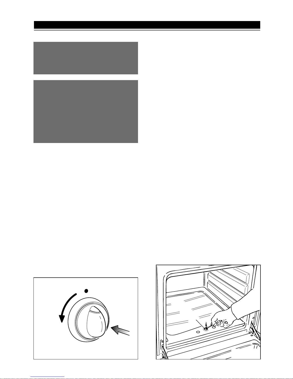
LIGHTING OF THE OVEN BURNER
1) Approach a flame to opening “A” fig.
4.2
2) Press thoroughly the knob and turn it
anti-clockwise position (fig. 4.1); the
indicator should match with the number 10.
3) Wait about ten seconds after the burner lighting before releasing the knob
(time of priming of the valve).
Close the oven door slowly.
4) Adjust the burner according to the
power required.
Should the flame of the burner estinguish
for any reason, the safety valve will cut
off automatically the gas flow to the thermostat.
To re-start operation, take the knob to
“off” position and repeat operations 1-23 as above explained.
Page 10
0
9
10
6
7
8
3
4
5
1
2
Fig. 4.3
For orientative purposes only, some
oven cooking indications are shown on
the following table:
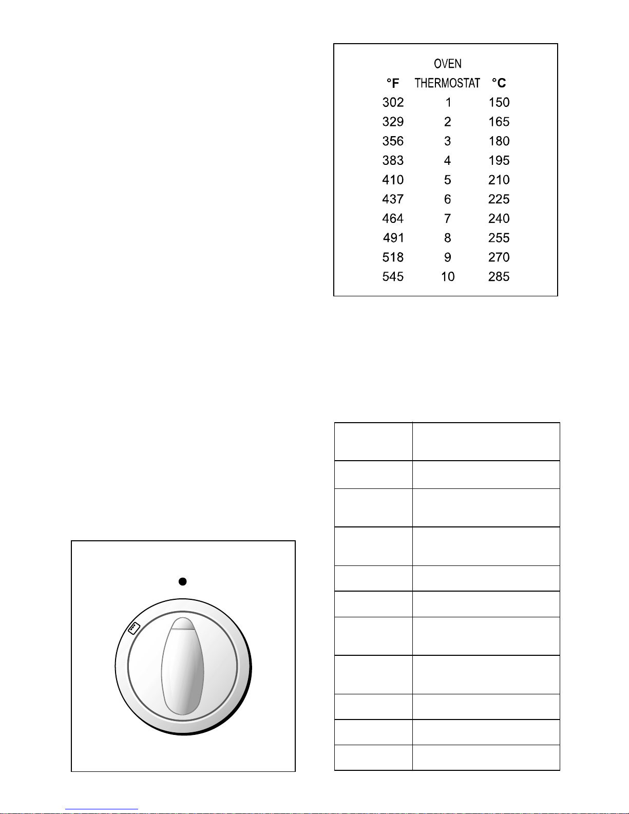
THERMOSTAT
DISHES
POSITION
1 Heating of foods
1
Meringue - Fruit pies
Cooked fruit
1 - 2
Cakes - Amaretti,
Vegetables
2 - 3 Lasagna - Cakes
3 - 4 Roast veal - Pie crusts
5 - 6
Wild game - Birds
Small fish - Roast pork
6 - 7
Large fish
Roast beef
7 - 8 Pizza - Red meats
8 - 9 Toasted sandwiches
10 Oven cleaning
OVEN BURNER THERMOSTAT
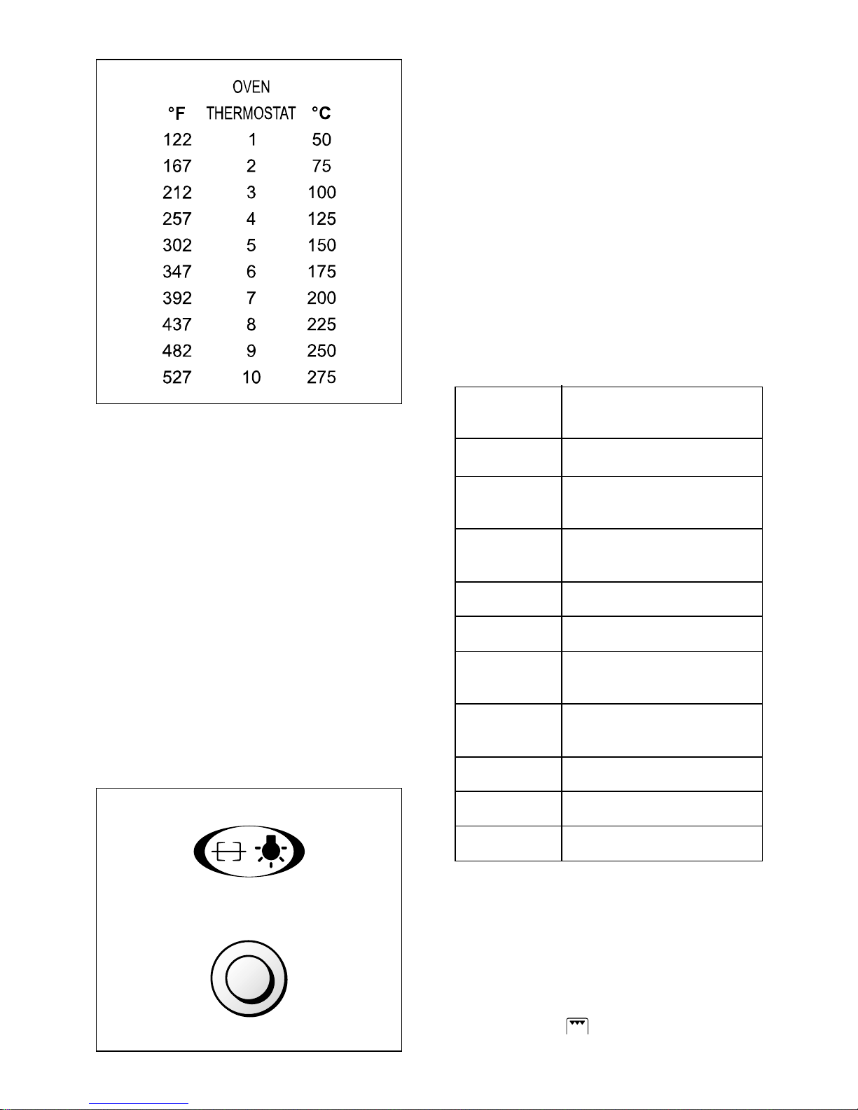
The numbers 1 to 10 (fig. 4.3) indicate
the increasing oven temperature value
(see table 4.4).
To regulate the temperature, set the
knob indicator onto the chosen number.
OVEN COOKING
To cook, before introducing the food,
pre-heat the oven to the desired temperature for the period of time indicated
on the table to left (table 4.4).
These preheating times indicate the
time that a cold and empty oven takes
to reach that temperature.
When the oven has reached the temperature, introduce the food, control the
check the cooking time and turn off the
oven 5 minutes before the theoretical
time to recuperate the stored heat.
Table 4.4
10
Page 11
11
GRILL BURNER
This burner makes the stainless steel
wire net red hot, which, generating infra
red rays, permits grilling.
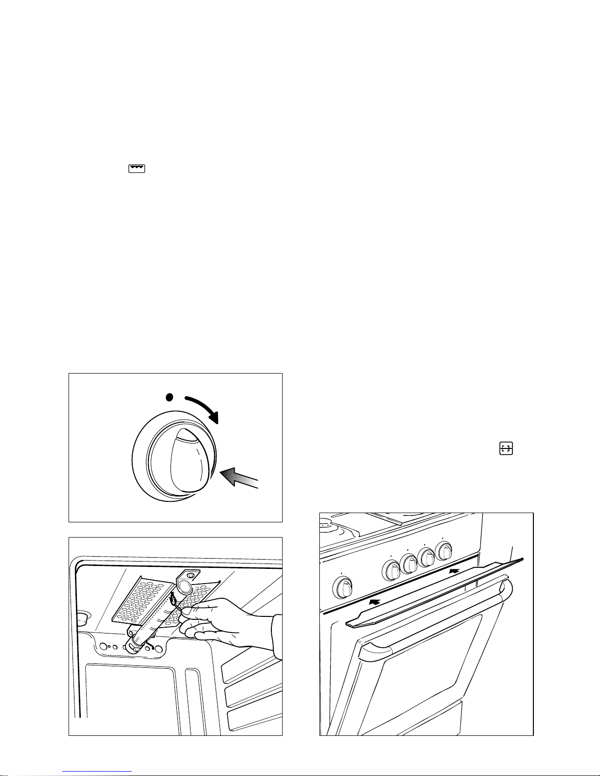
To turn on the grill burner:
1) Press thoroughly and turn clockwise
the oven gas thermostat knob to set
symbol .
2) Put a flame to the right and left side
of the burner for 2-3 seconds after
the thermostat has been opened (fig.
4.6).
3) Wait about ten seconds after the
burner lighting before releasing the
knob (time of priming of the valve).
Should the flame of the burner estinguish for any reason, the safety valve
will cut off automatically the gas flow to
the tap. To re-start operation, take the
knob to “off” position and repeat operations 1-2-3 as above explained.
Fig. 4.5
Fig. 4.6
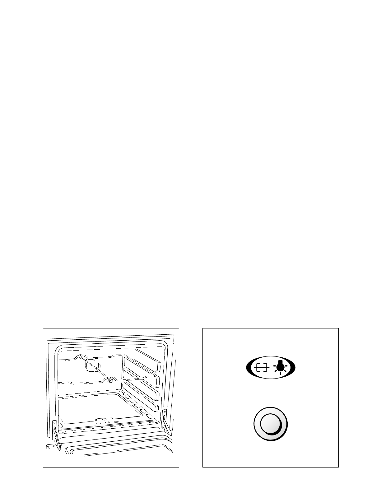
ROTISSERIE
Except for some models, the ovens are
equipped with a rotisserie for cooking on
the spit using the grill (fig. 4.9).
This device is made up of:
– an electrical motor mounted on the rear
part of the oven
– a stainless steel rod, equipped with a
detachable athermic grip and 2 recordable forks
– a rod support to be inserted into the
central rack holders of the oven.
The rotisserie motor is operated by the
switch indicated by the symbol on
the control panel (fig. 4.9).
Fig. 4.7
A
USE OF THE GRILL
Very important: the grill must always
be used with the oven door slightly
open (Fig. 4.7).
Mount shield “A” which serves to protect
the control panel from the heat.
Turn on the grill, as explained in the preceding paragraphs and let the oven preheat for about 5 minutes with the door
slightly open.
Introduce the food to be cooked, positioning the rack as close to the grill as
possible.
Page 12
12
USE OF THE ROTISSERIE
Very important: the rotisserie must
always be used with the oven door
slightly open and with shield "A”
mounted (Fig. 4.7).
– Insert the dripping pan into the lowest
rack holders of the oven and insert the
rod support into the intermediate rack
holders.
– Put the meat to be cooked onto the
rod, being careful to secure it in the
center with the special forks.
– Insert the rod into the motor opening
and rest it onto the support of the spit
collar; then remove the grip by turning
it to the left.
The rotation direction of the rotisserie
can be either clockwise or counter-clockwise.
Fig. 4.8
Fig. 4.9
OVEN LIGHT
Except for some models, the oven is
equipped with a light that illuminates the
oven to enable visually controlling the
food that is cooking.
This light is controlled by a switch on the
control panel (fig. 4.9).
Page 13
13
GENERAL FEATURES
The oven is furnished completely clean;
it is advisable, however, upon first use,
to turn the oven on to the maximum temperature (pos. 10 = 240°C) for about 15
minutes to eliminate possible traces of
grease on the heating elements.
The convection oven is eqipped with 3
electrical heating elements:
– 2 elements (upper and lower) for nor-
mal oven cooking
– 1 grill element, on the top of the oven,
for grilling which must be done with
the oven door slightly open and with
the protection shield for the control
panel mounted.
The input of the element is:
– upper element, 960 W
– lower element, 1340 W
– grill element, 1900 W
ELECTRICAL THERMOSTAT
Turn on the oven or grill elements by
turning the switch that is also provided
with a thermostat to control the oven
temperature.
To regulate the temperature or function,
turn the control knob until the required
number or symbol is level with the vertical line on the control panel.
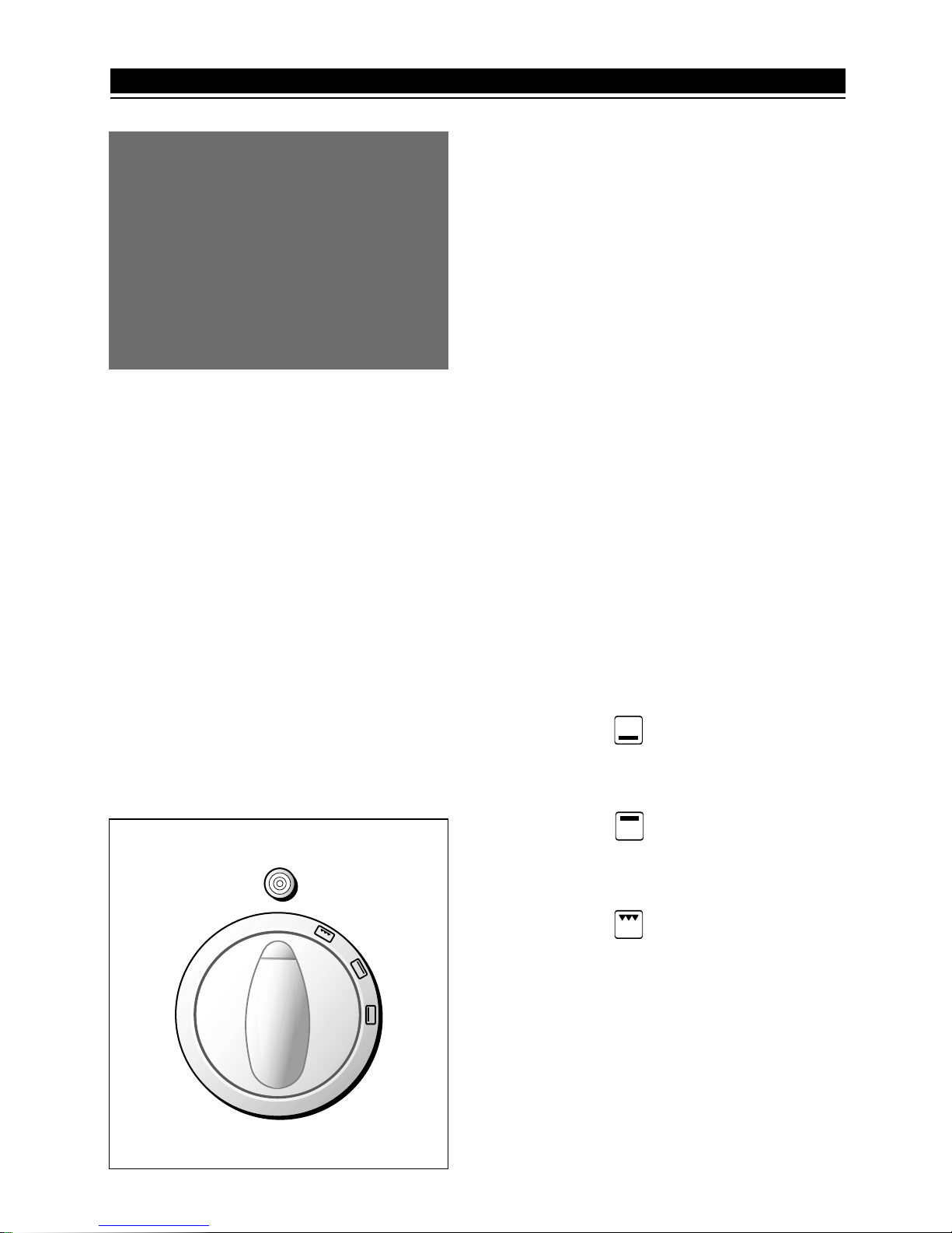
The switch/thermostat symbols indicate:
– Position “0”= off
– Position from “1 to 10” = simultaneous
operation of the 2 elements. The numbers correspond to the temperature
shown in the table 5.2.
The elements will turn on and off automatically depending on the temperature required commanded by the thermostat.
– Position = lower element only
in operation without temperature
control.
– Position = upper element
only in operation
without temperature control.
– Position = grill element in
operation without
temperature control (see specific
paragraph).
The automatic turning on and off of the
elements is signalled by a light above
the knob.
0
1
2
3
4
5
6
7
8
9
10
Fig. 5.1
The glass of the oven door reaches
high temperatures during operation.
Keep children away.
For child safety, a door guard can be
fitted to prevent contact with the hot
glass.
The door guard is supplied as an
accessory on request. Contact one of
our dealers or Service Centre and
indicate the relevant appliance model.
5 - ELECTRICAL CONVECTION OVEN
Page 14
14
Fig. 5.3
OVEN LIGHT
The oven is equipped with a light that
illuminates the oven to enable visually
controlling the food that is cooking.
This light is controlled by a switch on the
control panel (fig. 5.3).
OVEN COOKING
To cook, before introducing the food, preheat the oven to the desired temperature
for the amount of time indicated in table
5.2.
The preheating times shown indicate the
time that a cold and empty oven takes
to reach that temperature.
When the oven has reached the desired
temperature, introduce the food, control
the cooking time and turn off the oven 5
minutes before the theoretical time to
recuperate the stored heat.
For orientative purposes only, some
oven cooking indications are shown on
the following table:
THERMOSTAT
DISHES
POSITION
1 - 4 Heating of foods
4 - 5
Meringue - Fruit pies
Cooked fruit
5 - 6
Cakes - Amaretti,
Vegetables
6 Lasagna - Cakes
6 - 7 Roast veal - Pie crusts
8
Wild game - Birds
Small fish - Roast pork
9
Large fish
Roast beef
9 - 10 Pizza - Red meats
10 Toasted sandwiches
10 Oven cleaning
ELECTRICAL GRILL
The grill element has got 1900 W input
and is controlled by the switch/thermostat by positioning the knob onto the relevant symbol .
Page 15
15
Fig. 5.4
A
Fig. 5.5
USE OF THE GRILL
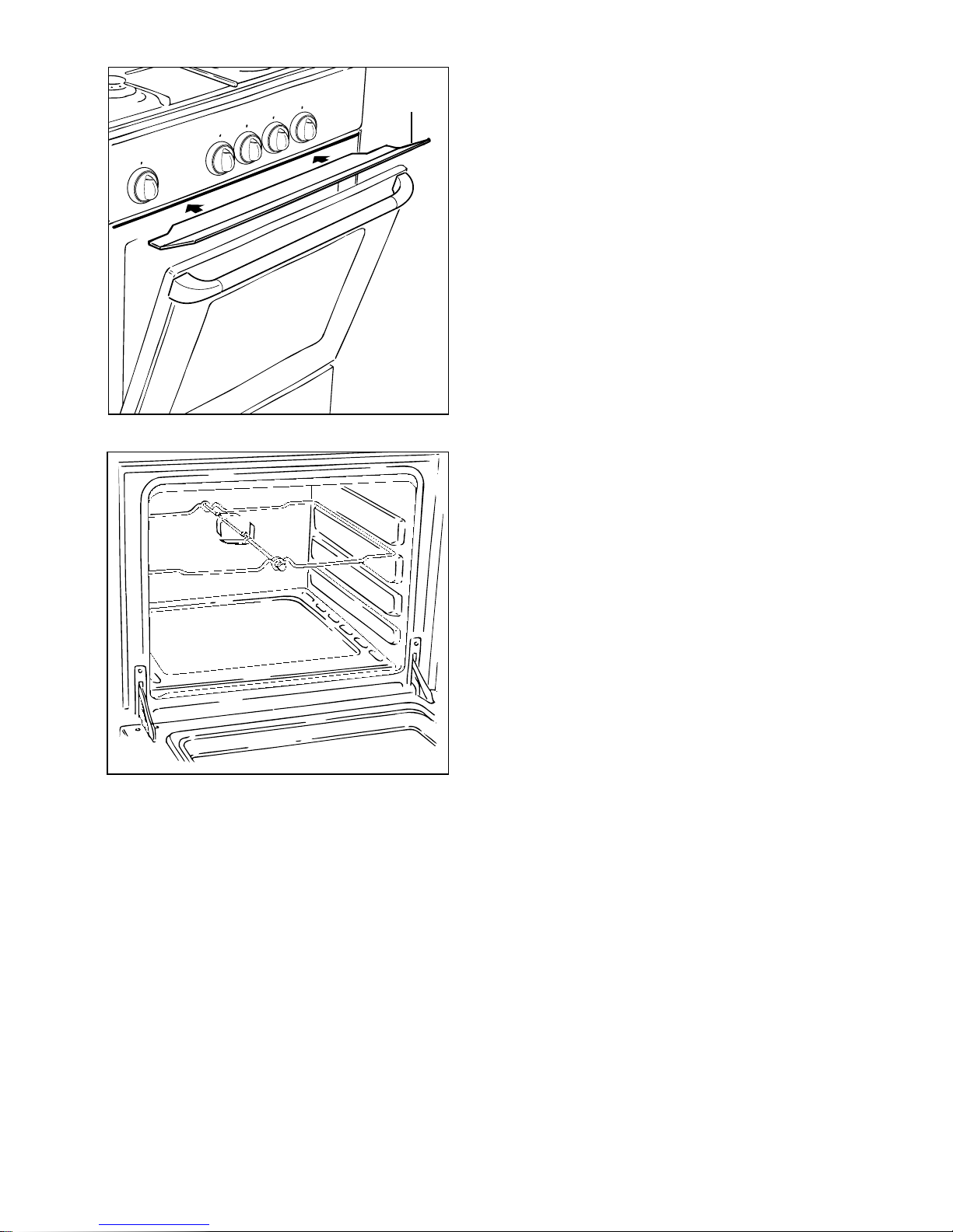
Very important: the grill must always
be used with the oven door slightly
open (Fig. 5.4).
The oven door becomes very hot during operation.
Keep children away.
Mount shield “A” which permits to protect the control panel from the heat.
Turn on the grill, as explained in the preceding paragraphs and let the oven preheat for about 5 minutes with the door
slightly open.
Introduce the food to be cooked, positioning the rack as close to the grill as
possible.
ROTISSERIE
Except for some models, the ovens are
equipped with a rotisserie for cooking on
the spit using the grill.
This device is made up of:
– an electrical motor mounted on the rear
part of the oven
– a stainless steel rod, equipped with a
detachable athermic grip and 2 recordable forks
– a rod support to be inserted into the
central rack holders of the oven.
The rotisserie motor is operated by the
switch indicated by the symbol on the
control panel (fig. 5.2).
USE OF THE ROTISSERIE
Very important: the rotisserie must
always be used with the oven door
slightly open and with shield "A”
mounted (Fig. 5.4).
– Insert the dripping pan into the lowest
rack holders of the oven and insert the
rod support into the intermediate rack
holders.
– Put the meat to be cooked onto the
rod, being careful to secure it in the
center with the special forks.
– Insert the rod into the motor opening
and rest it onto the support of the spit
collar; then remove the grip by turning
it to the left.
The rotation direction of the rotisserie
can be either clockwise or counter-clockwise.
Page 16
16
MECHANICAL TIMER
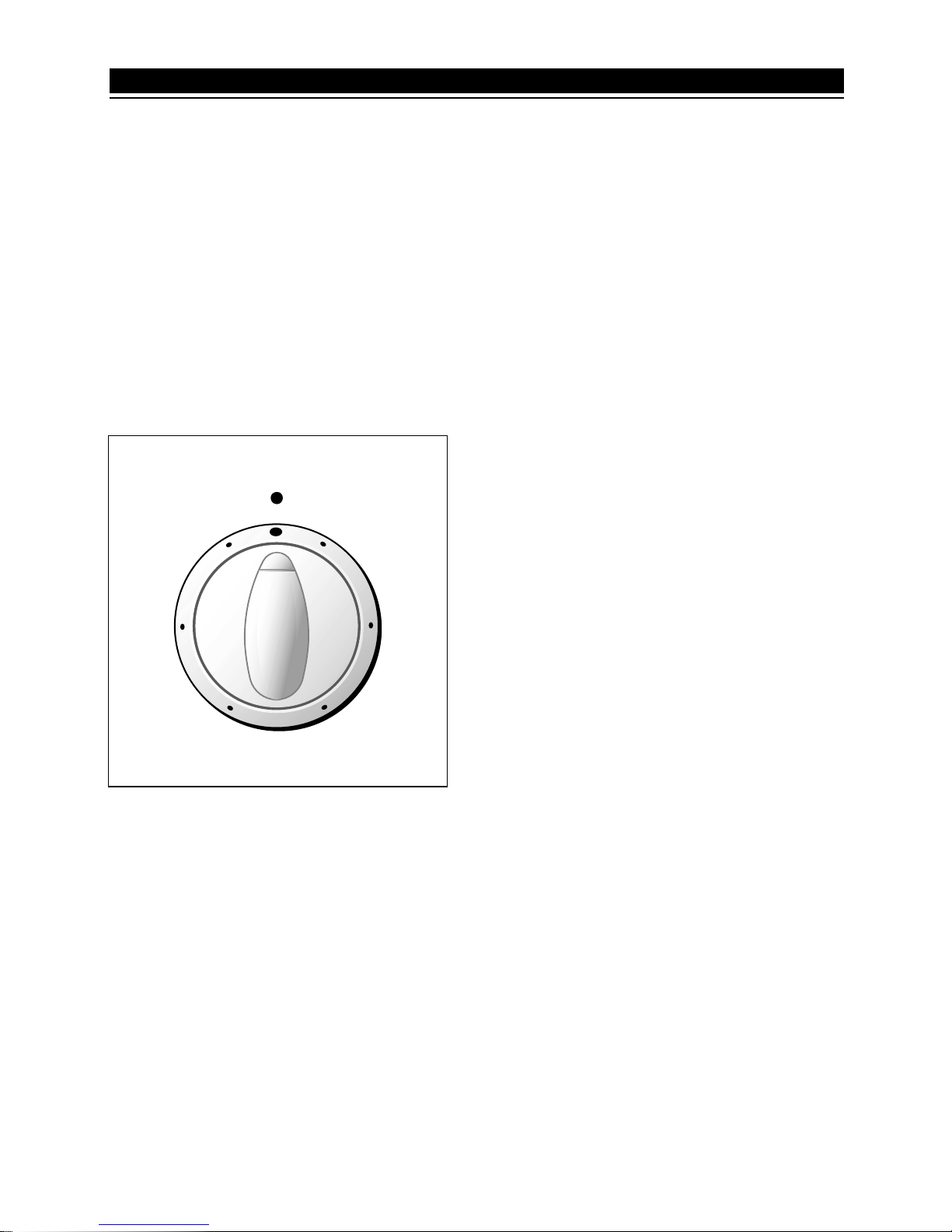
The timer is equipped with a time buzzer
and may be regulated for a maximum
period of 60 minutes.
The regulating knob (fig. 6.1) must be
turned in a clockwise direction until it
reaches the 60 minutes position and
then turned to the desired time by turning
the knob in a counterclockwise direction.
10
20
30
40
50
Fig. 6.1
6 - TIMER
Page 17
17
* When the appliance is not being used,
it is advisable to keep the gas tap
closed.
From time to time check to make sure
that the flexible tube that connects the
gas line or the gas cylinder to the appliance is in perfect condition and eventually substitute it, if it shows signs of
wearing or damage.
* The periodical lubrification of the gas
taps must be done only by specialized
personnel. In case of difficulty in the gas
taps operation, call Service.
Attention:
The cooktop becomes very hot
while in operation.
The oven door becomes very hot
during operation.
Keep children away.
Fig. 7.1
S
D
R
7 -
GENERAL ADVICE
Do not lower the glass lid when burn-
ers or electric plates are still hot or
when the oven is working or still hot.
Do not lay on the glass lid hot pans
and heavy kitchen utensils.
CAUTION: glass lids may shatter when
heated. Turn off all the burners
before shutting the lid.
GLASS LID
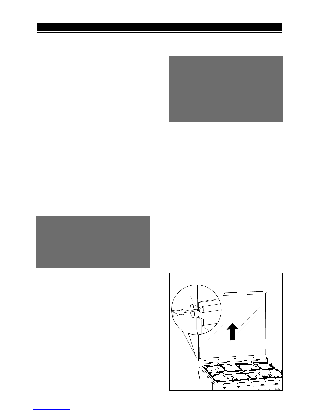
For cleaning purposes, the lid can be
easily removed upwards once taken to
the upright position.
Should the hinges slip off, replace them
in their housing being careful that:
– The right housing must receive the
hinge marked “D” while the left housing must receive the hinge marked “S”
(Fig. 7.1).
REGULATING OF THE BALANCE
Lower the lid and check the correct balance. While opened at 45° it should
hang up.
If necessary, register the calibration of
the hinge springs using the screws “R”
(fig. 7.1).
Page 18
18
GENERAL ADVICE
It is advisable to clean when the appliance is cold and especially for cleaning
the enamelled parts.
Avoid leaving alcaline or acidic substances (lemon juice, vinegar, etc.) on
the surfaces. Avoid using cleaning products with a chlorine or acidic base.
ENAMELLED PARTS
All of the enamelled parts must be
washed only with a sponge and soapy
water or with non-abrasive products.
Dry, preferably, with deer skin.
HOT PLATE
Foods burned on the hot plates must
always be cleaned dry.
Do not use water to avoid the forming
of rust. Be careful with the central feeler
of the automatic plates, it must never be
shined and must only be cleaned with a
damp cloth.
After its use, pour a bit of oil onto the
warm plate and rub with a cloth.
Always switch the cooker off at the
mains isolating switch before cleaning or touching any electrical part.
BURNERS, GRATES AND RACKS
These parts may be removed and
washed with suitable products.
The burners and their caps must be well
dried after cleaning and put back perfectly into their slots.
It is very important to verify the positioning of the burner-caps because a misplacing in their slots can cause serious
damage.
In the appliances with electrical ignition
for the burners, verify that the electrode
is always cleaned well as to permit the
regular snap of the spark.
8 - CLEANING AND MAINTENANCE
OVEN
The oven must always be cleaned after
every use, using suitable products and
keeping in mind that its operation for 30
minutes on the highest temperature eliminates most grime reducing it to ashes.
The clean-up of the oven with catalytic
self-cleaning enamel is done automatically during cooking, and therefore no
intervention is necessary.
Only when the grime is particularly resistant it is advisable to increase the cleaning time leaving the electrical elements
on at the maximun temperature, with the
oven empty. It is mandatory not to use
abrasive substances so as not to damage the self-cleaning coating.
Fig. 8.1
OVEN DOOR
The oven door is cleaned in the same
way that is advisable for the enamelled
surfaces.
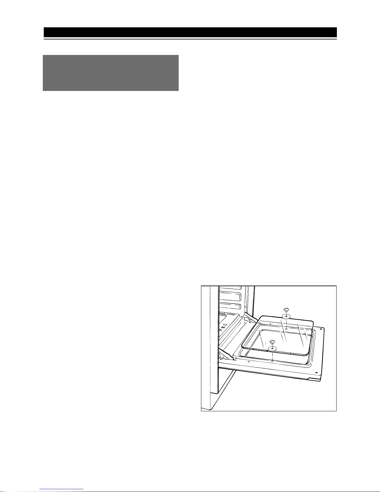
The internal glass of the oven door can
be easily removed for cleaning by
unscrewing the two lateral fixing screws
(fig. 8.1).
SUBSTITUTION OF THE OVEN LAMP
Before replacing the oven lamp, make
sure to disconnect the appliance mains.
The light bulb must be a type resistant
to high temperatures (300° C).
Page 19
19
BATTERY INSTALLATION
BATTERY INSTALLATION
1,5 V
Fig.8.2
Fig.8.3
Models with battery ignition
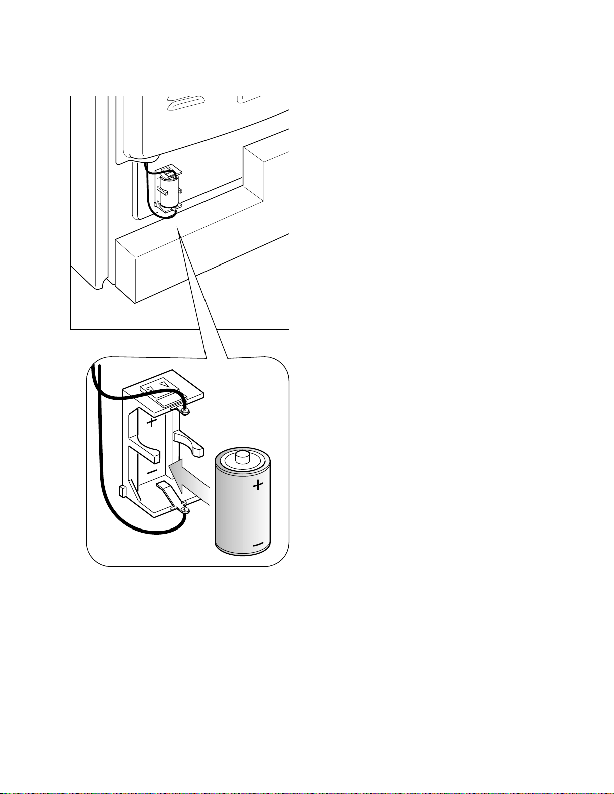
INSTALLING THE BATTERY
Insert a type C battery (1.5 Volt) into
the battery compartment on the back
of the cooker (fig. 8.2).
This battery is the power supply for
the electronic ignition of gas burners.
Batteries last on average for about two
years (alkaline battery) depending on
how often the electronic ignition is
used.
Notes for battery installation or
replacement:
- Only use a type C 1.5 Volt battery.
- Check for correct polarity (fig. 8.3
and label to the side of the battery
compartment).
Important notes:
- Remove the battery if the cooker is
not going to be used for a long time.
- If the battery leaks, replace it immediately. Avoid touching the leaked
liquid and make sure it does not
come into contact with clothes or
other items.
- Clean the battery compartment carefully before installing the new one.
- Note: The battery is a potential source of danger for children. Keep them
away.
- Dispose of flat batteries properly.
Page 20
20
LOCATION
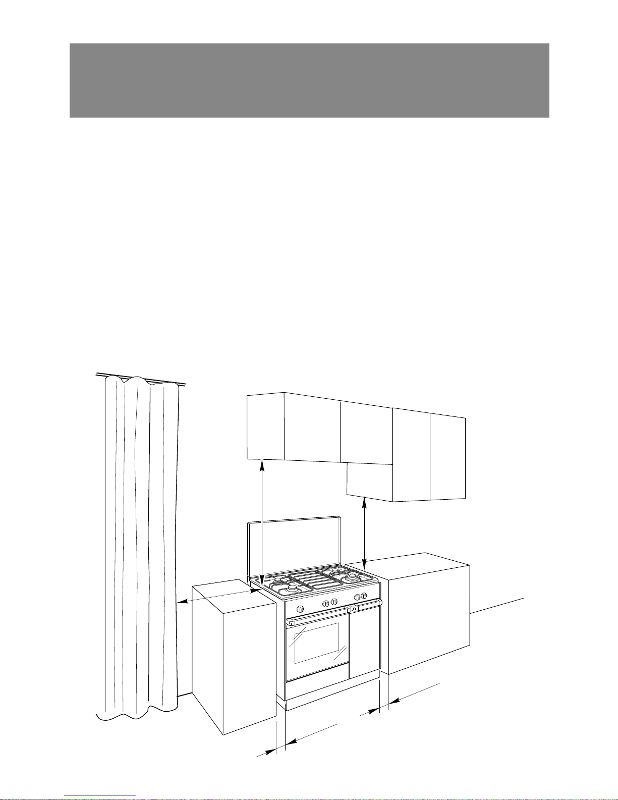
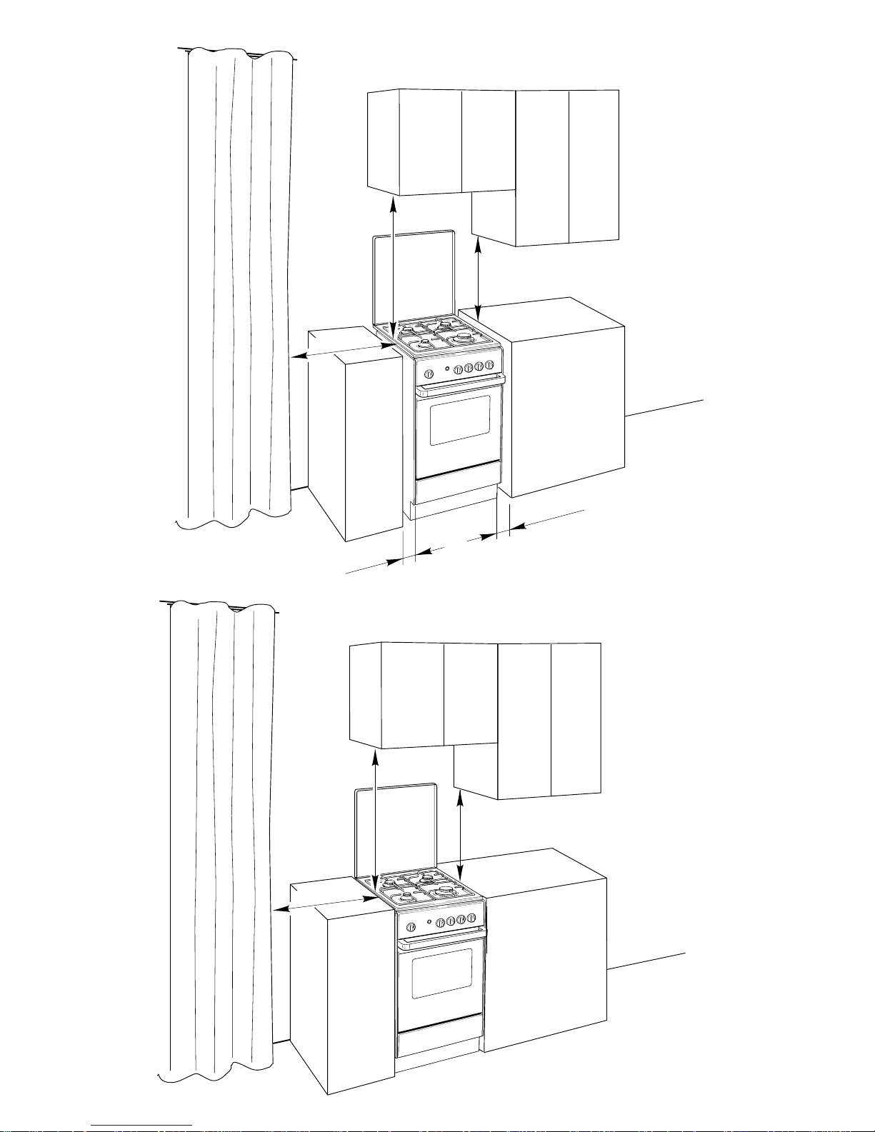
The cooker has “type X” or “Class 1”overheating protection so that it can be installed
next to a cabinet whose height is greater than that of the cooker.
It is advisable that the kitchen furniture near the sides of the cooker is made of
heat resistant material, minimum 75 °K.
500 mm
20 mm
20 mm
800 mm
500 mm
AAddvviiccee ffoorr tthhee iinnssttaalllleerr
Fig. 8.4a
Page 21
21
500 mm
800 mm
20 mm
20 mm
500 mm
GAS
OVEN
800 mm
500 mm
ELECTRIC
OVEN
500 mm
Fig. 8.4c
Fig. 8.4b
Class 1
Type X
Page 22
22
CHOOSING SUITABLE
SURROUNDINGS
In the room chosen to accommodate the
gas appliance, there must be an adequate natural draft to allow combustion
of the gas.
The natural draft must be produced
directly by one or more vents made in
the external walls and providing a total
opening of at least 100 cm
2
.
The vents must be positioned close to
the floor, preferably on the opposite side
to the combustion discharge outlet and
must be designed in such a way that
they cannot be obstructed either from the
inside or the outside.
When it is not possible to provide the
necessary vents, the draft may be supplied from an adjacent room, ventilated
in the required manner, provided it is not
a bedroom or an area at risk.
In this event, the door of the kitchen must
be opened to allow the draft to enter the
room.
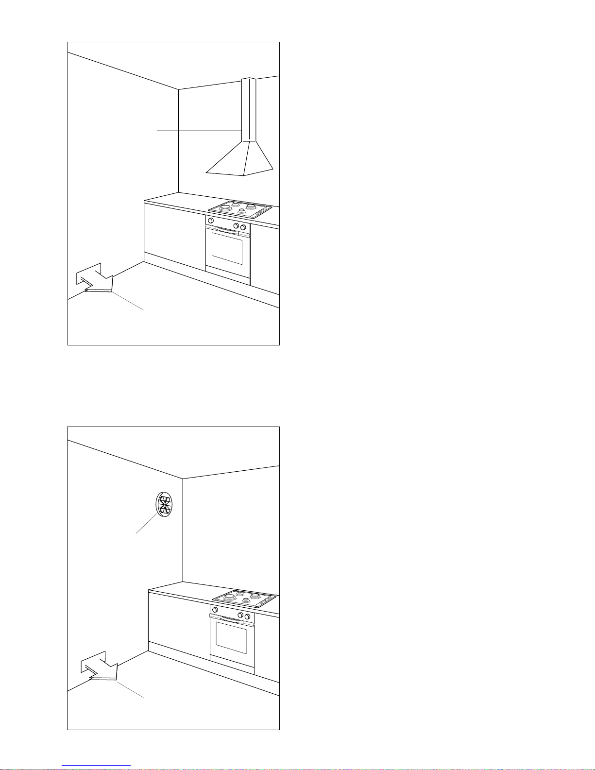
Fig. 8.5
Fig. 8.6
Air vent
A
Extractor hood
for products of
combustion
Electric fan to
extract products
of combustion
DISCHARGING PRODUCTS OF
COMBUSTION
Extractor hoods connected directly to the
outside must be provided, to allow the
products of combustion of the gas appliance to be discharged (fig. 8.5).
If this is not possible, an electric fan may
be used, attached to the external wall or
the window; the fan should have a
capacity to circulate air at an hourly rate
of 3-5 times the total volume of the
kitchen (fig. 8.6).
The fan can only be installed if the room
has suitable vents to allow air to enter,
as described under the heading
“Choosing suitable surroundings”.
Page 23
23
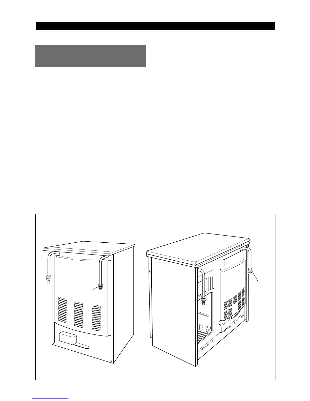
Plug
Plug
INSTALLATION
The appliance is predisposed and adjusted to operate with the gas indicated on
the specifications plate applied onto the
appliance.
GASES
The gases used for the operation of
cooking appliances may be grouped by
their characteristics into two types:
– L.P.G. (in cylinders)
– NATURAL GAS
– TOWN GAS
The walls adjacent to the oven must
be of material resistant to heat.
Fig. 11.1
If the appliance must be operated with a
gas different than that indicated on the
plate, it is necessary to execute the following operations:
1) Gas connection
2) Replacement of the top injectors
3) Regulating of the primary air of the
top burners
4) Adjustment of the minimum of the top
5) Replacement of the injector of oven
burner
6) Replacement of the injector of grill
burner
7) Primary air of oven burner
8) Primary air of grill burner
9) Adjustment of the oven burner minimum
11 - GAS SECTION
Page 24
24
These operations must be carefully fulfilled as follows.
1 - GAS CONNECTION
– Connect the cooker to the gas mains
utilizing rigid or flexible pipes.
– The connection must be executed to
the rear of appliance (fig. 11.1); the
pipe do not cross the cooker.
– The unused end inlet pipe of the cook-
er (left or right) must be closed with
the plug interposing the gasket.
L.P.G. (G30/G31)
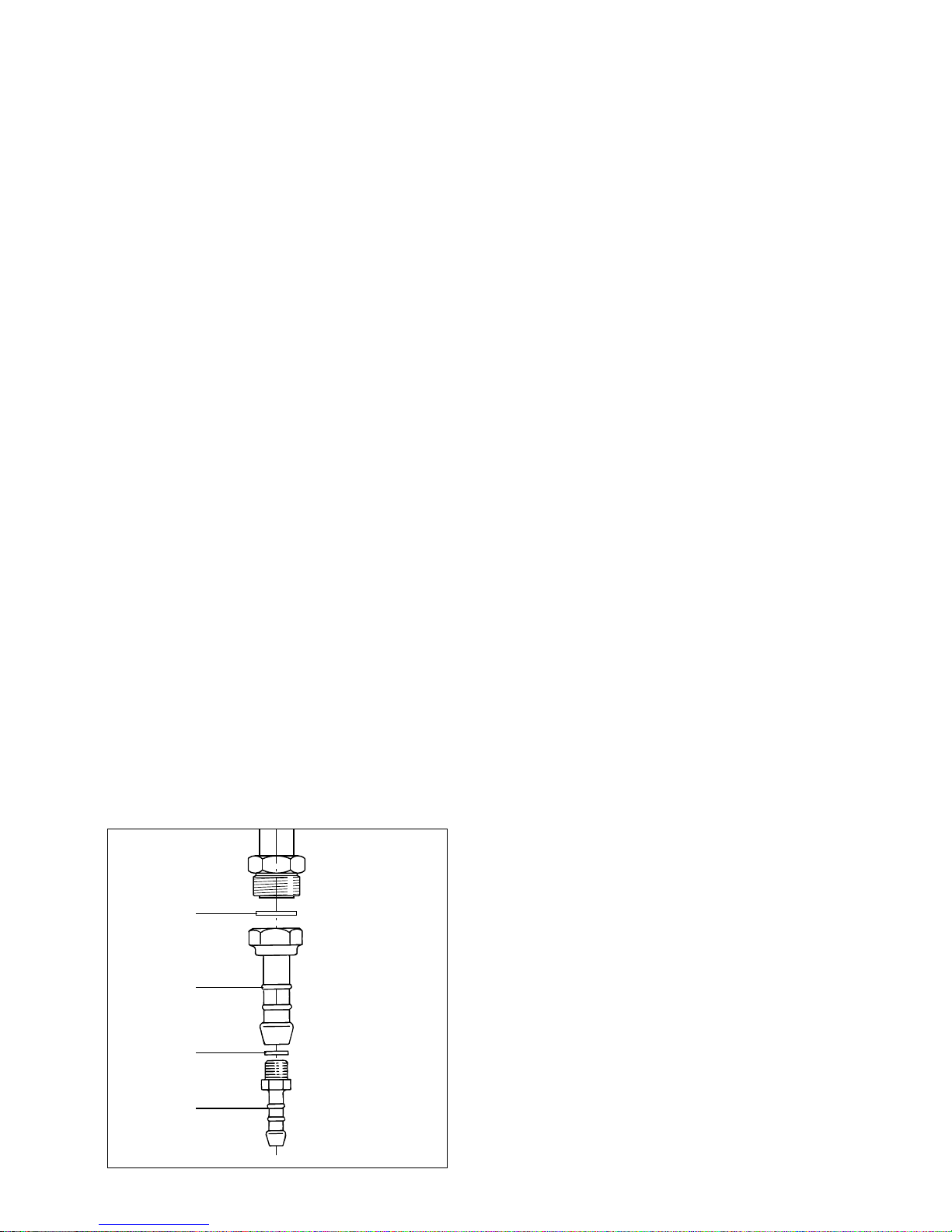
– If not mounted, fit up the holder “R” to
the holder “M” interposing gasket “Q”.
– Connect the cooker to the cylinder
pressure regulator by a suitable rubber
tube (inside diameter 8 mm).
Natural gas (G20) or Town Gas (G110)
– Remove the holder “R”.
– Connect the cooker to the gas net by
a suitable rubber tube (inside diameter
13 mm).
The rubber tube must be as short as
possible, without contractions or
kinks.
IMPORTANT:
After connecting to the mains, check
that the couplings are correctly
sealed, using soapy solution, but
never a naked flame.
Gas connection for:
The fitting (fig. 11.2) is made up of:
– 1 adapter “M” for Natural Gas (G20)
or Town Gas (G110)
D
M
Q
R
Fig. 11.2
– 1 adapter “R” for L.P.G. (G30/G31)
– gasket “D” and “Q”
Page 25
25
GAS CYLINDER CONNECTION
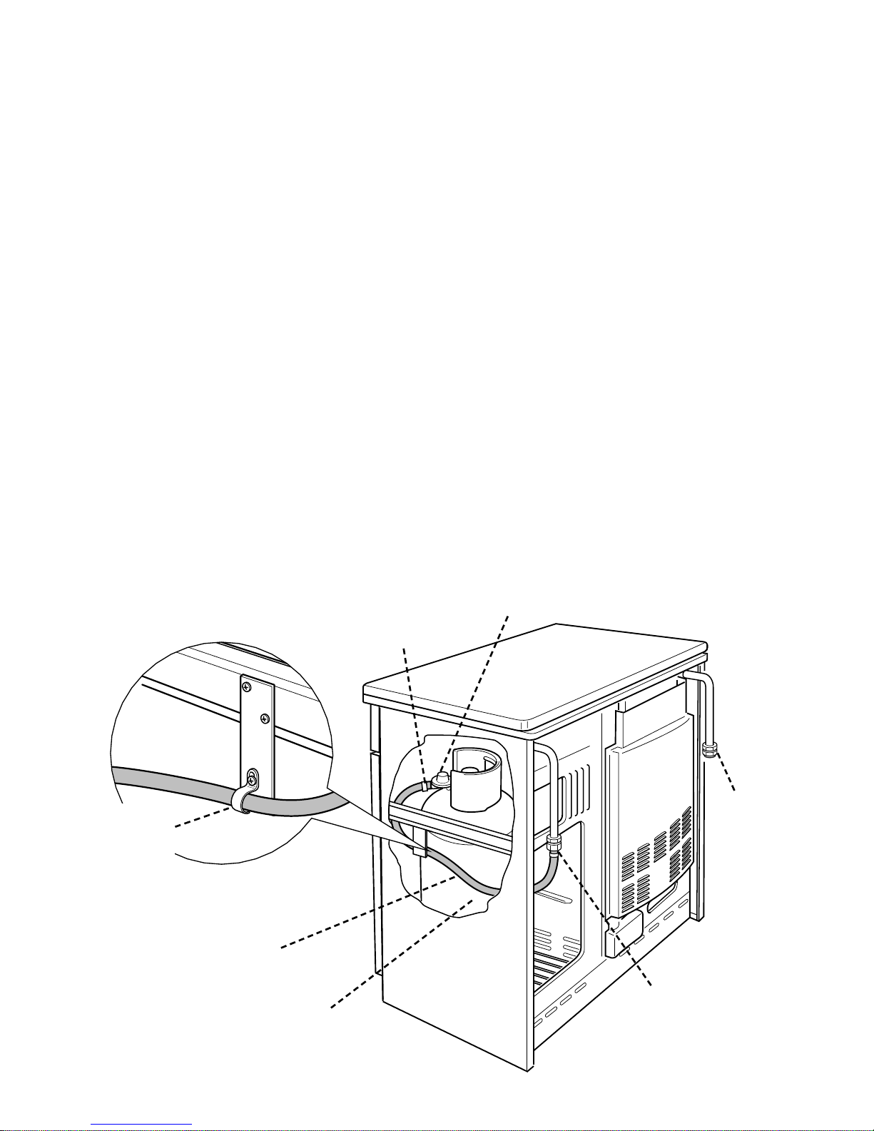
The connection between the hose connector on the cooker and the regulator
of the gas cylinder must be made using
a 60 cm long flexible hose conforming
to applicable standards, and hose
clamps.
The connection hose must be inserted
in the hose support (fig. 11.4) and
pushed over the hose connectors to the
full depth.
IMPORTANT:
Only max 13 kg cylinders may be used
in the cylinder compartment, and they
must be positioned in such a way that
the regulator and shut-off cock are easily
accessible.
When changing the gas cylinder, do not
withdraw the hose from the hose
support G.
Installation and replacement of gas
cylinders must only be carried out by
qualified persons.
Fig. 11.4
Gas cylinder:
13 kg maximum
Hose length:
60 cm
Pressure regulator
Hose
clamp
Hose
clamp
Plug
G
Hose
support
Page 26
26
Flame Flame Flame
faulty in correct with excess
primary air primary air
long, vellow clear short and sharp
and interior blue too blue interior
trembling cone cone tending to
detach
CAUSE
air regulating correct air regulating
tube, too distance of tube, too
closed the tube open
Fig. 11.6
M
J
A
3 - ADJUSTMENT OF PRIMARY AIR
OF TOP BURNERS
By operating on the screw “M”, reset the
air adjuster “A” according to the instructions indicated on the table for the choice
of the injectors, where the distance
between injector and air adjuster is recommended (in mm).
Before lowering the cooktop, set the
burners on their sites and light them in
order to check whether the flames are
correct, as per the specifications given in
the next page. In case of uncorrect
flame, lift or lower the air adjuster.
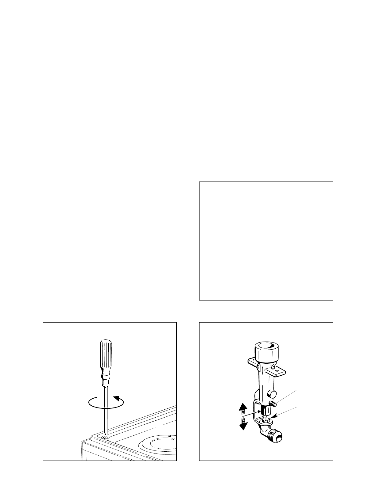
2 -
INJECTORS REPLACEMENT OF
TOP BURNERS
To replace the injectors, raise the cooktop in the following manner (fig. 11.5):
– Litf the cooking top (fig. 11.5)
– Fully raise the adjusting air tube A (fig.
14.4) in order to easily reach the injector.
– Loose the screw “M” of each injector
and fully raise the adjusting air tube
“A” (fig. 11.6).
– By a polygonal 7 spanner, remove the
injector “J” from their housing and
replace it by the proper one according
to the kind of gas (see injectors table).
Fig. 11.5
Page 27
27
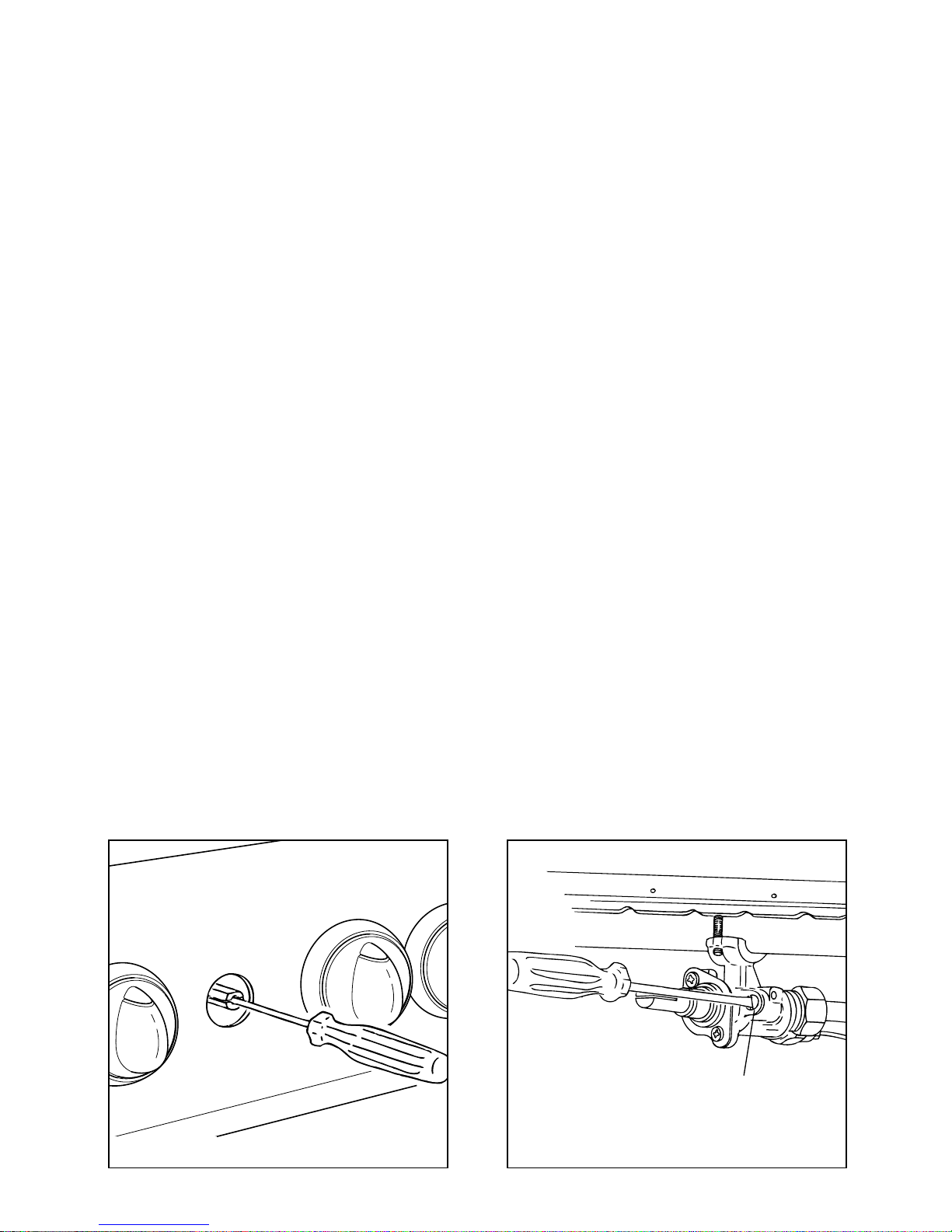
4 - ADJUSTMENT OF THE MINIMUN
OF THE TOP BURNERS
Considering that in the minimum position
the flame must have a length of about 4
mm and must remain lit even with a
brusque passage from the maximum
position to that of minimum.
The flame adjustment is done in the following way:
– Turn on the burner
– Tum the tap to the MINIMUM position
– Take off the knob
– With a small flat screwdriver turn the
screw inside the tap rod to the correct
regulation (fig. 11.7).
In the taps with safety valves tur the
screw F (fig. 11.8).
Normally for G30/G31 gas, tighten up
the regulation screw.
Fig. 11.7 Fig. 11.8
F
Page 28
28
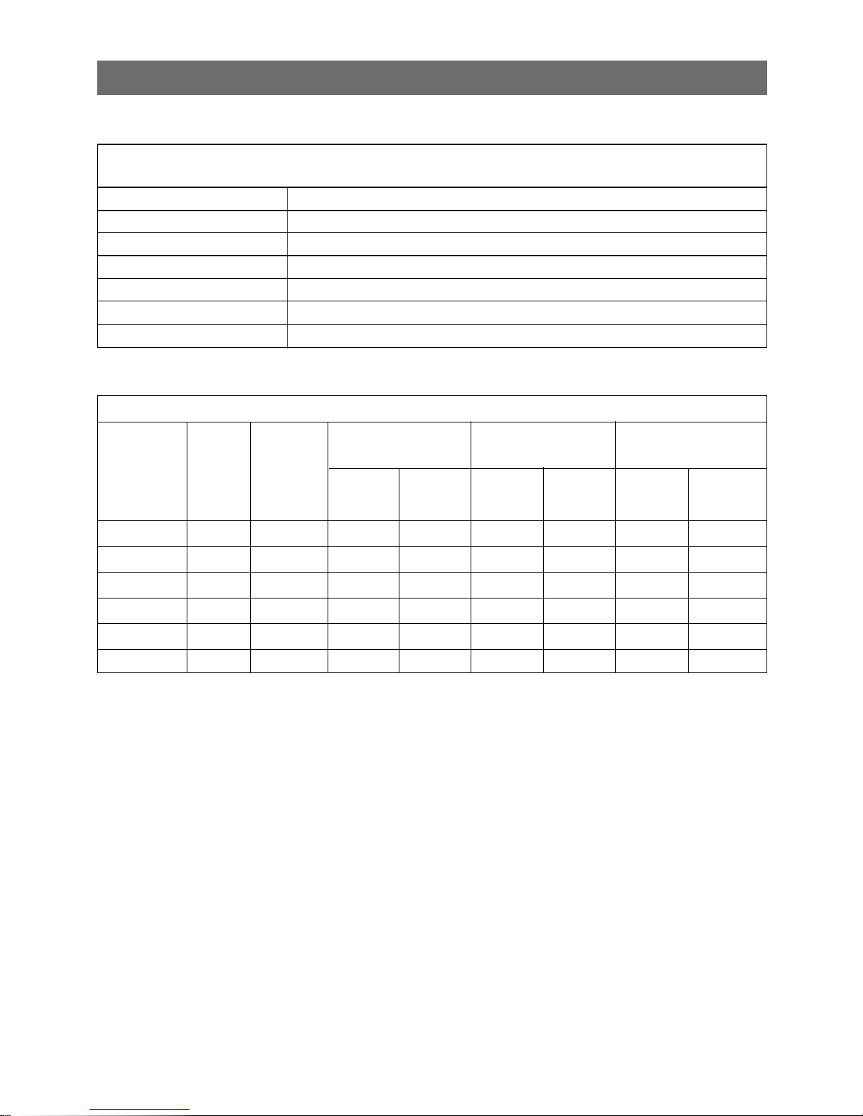
TABLE FOR THE CHOICE OF THE INJECTORS
I
NCREASE OF AIR NECESSARY FOR GAS COMBUSTION (2 m
3
/h kW)
BRULEURS Air necessary for combustion [m
3
/h]
A
uxiliary
(A) 1,80
Semi-rapid (SR)
3,10
Rapid burner (R1) 6,10
Rapid burner (R2) 5,10
Thermostat oven 6,40
Grill 4,00
TABLE FOR THE CHOICE OF THE INJECTORS
G 30 – 30 mbar G 20 – 20 mbar G 110 – 8 mbar
(L.P.G.) (NATURAL GAS) (TOWN GAS)
BURNERS Rating Reduced Ø mm mm ring Ø mm mm ring Ø mm mm ring
type Watt power [W] injector opening injector opening injector opening
A 900 300 0.47 3 0.70 1.5 1.30 1
SR 1550 380 0.62 5.7 0.88 2 1.70 1,5
R 2550 500 0.78 6.5 1.15 2 2.20 1,5
DR 3500 850 0.92
Fully open 1.35 5 2.80 5
OVEN 3200 850 0.86
Fully open 1.30 5 2.70 5
GRILL 2000 – 0.72
Fully open 1.05 9 2.15 9
Page 29
29
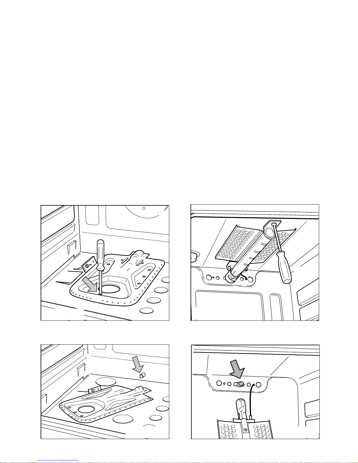
5 - REPLACEMENT OF THE OVEN
BURNER INJECTOR
According to the type of gas, the oven
injectors are to be similarly replaced, as
stated on the table of the paragraph 2,
operating as follows:
– remove the oven bottom
– unscrew the burner fixing screw (Fig.
11.9)
– slip the burner itself from the oven (Fig.
11.10)
– remove the injector from the connec-
tion and replace it with the proper one
6 - REPLACEMENT OF THE GRILL
BURNER INJECTORS
– remove the grill burner by unscrewing
the front screws (fig. 14.8)
– substitute the injector (fig. 14.9) with a
number 7 tubular spanner
– re-mount the burner.
Fig. 11.9
Fig. 11.10
Fig. 11.11
Fig. 11.12
Page 30
30
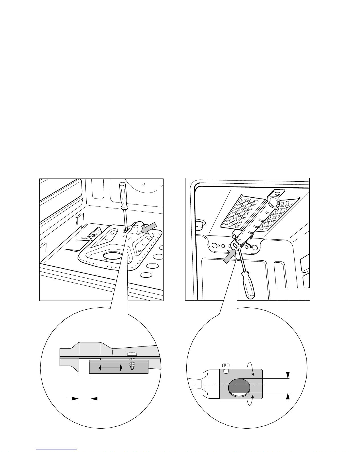
8 - PRIMARY AIR OF THE GRILL
BURNER
With a screwdriver untighten the screw
(fig. 14.11) and turn the air ring to close
or open the air flow, according to the Air
Adjustment Table.
Light the burner and check the flames.
Fig. 11.14
7 - PRIMARY AIR OF THE OVEN
BURNER
With a screwdriver untighten the two
screws (fig. 14.10 and move forward or
backward to close or open the air flow,
the air ring according to the Air
Adjustment Table.
Light the burner and check the flames.
Fig. 11.13
Ring opening
(see “Injector Table”
on page 25)
Ring opening
(see “Injector Table”
on page 25)
Page 31
31
LUBRIFICATION OF THE GAS TAPS
If the gas tap becomes stiff, it is necessary to dismount it accurately clean it
with gasoline and spread a bit of special
grease resistant to high temperatures on
it.
The operations to be executed are as
follows:
– Turn off the valve of the gas supply
or of the cylinder.
– Remove the control panel as indicated
in previous paragraphs.
– Unscrew the two screws that block the
coupling flange.
– Remove the coupling flange and the
spring of the knob holder rod.
– Lift the gas regulation cone.
– Accurately clean it with gasoline.
– Accurately spread it with a bit of
grease suitable for high temperatures
being careful not to obstruct the holes
for the gas passage.
– Re-mount all of the pieces, verifying
that the spring and the rotation pin of
the cone mounted on the knob holder
rod are perfectly in place.
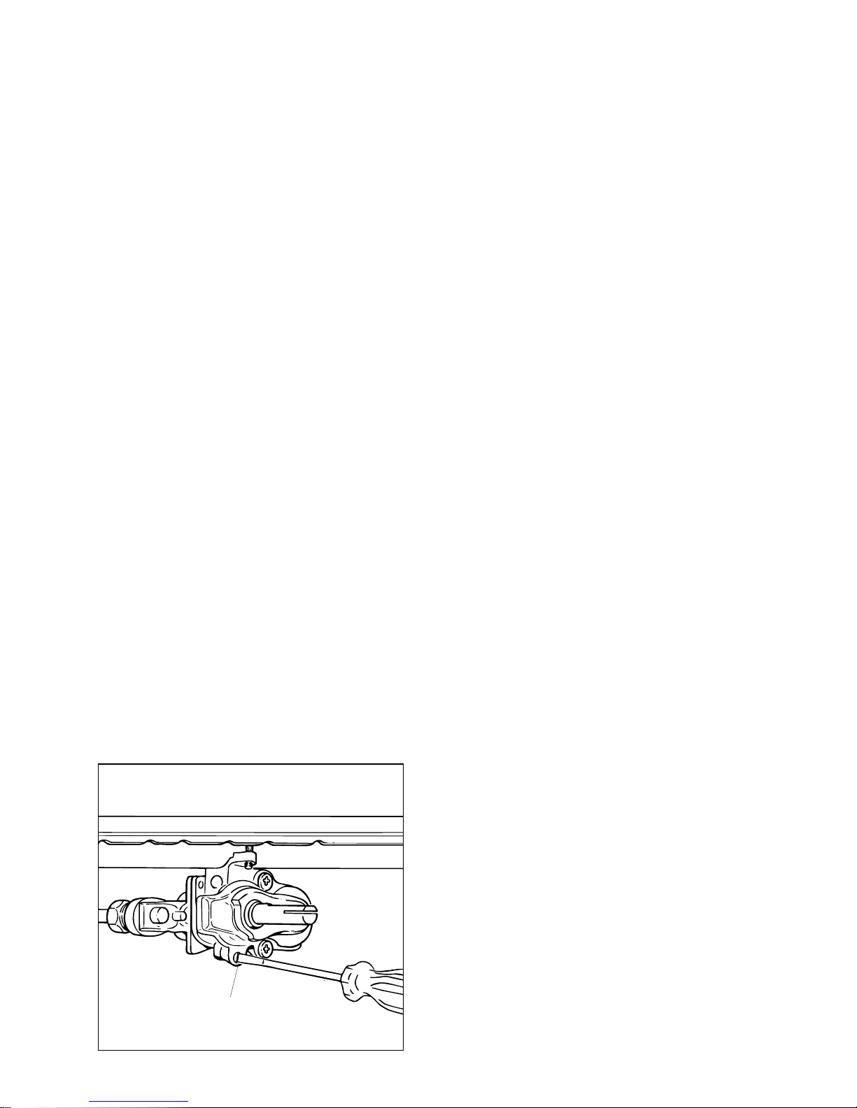
9) REGULATING OF THE OVEN
MINIMUM
To be effected only for the oven burner
(as the grill burner has an only fixed
input) operating on the thermostat as follows:
– Light the oven taking the knob to posi-
tion 10 (max)
– remove the knob and by a thin screw-
driver (3 mm section - 100 mm long)
unscrew of about a half turn the bypass, passing through the front panel
hole (see picture below)
– fit the knob and let the oven heat for
10 minutes, then take the knob to
position 1 allowing the thermostat to
work under by-pass G (fig. 9.11).
– after further removal of the knob, stop
slowly the screw by-pass (being careful not to turn the knob) until the flame
reaches 3-4 mm high.
N.B. For LPG the by-pass screw must
be fixed thoroughly.
Fig. 9.11
G
Page 32

32
– If the power supply cable is damaged
it must be substituted by a suitable
cable available in the after sales service.
N.B. For connection to the mains, do
not use adapters, reducers or branching devices as they can cause overheating and burning.
If the installation requires alterations to
the domestic electrical system or if the
socket and appliance plug are incompatible, call an expert.
He should also check that the socket
cable section is suitable for the power
absorbed by the appliance.
ELECTRICAL FEEDER CABLE
The cooker is predisposed to operate in
alternated mono-phase voltage of
230 V - 50 Hz.
To operate the appliance just plug in the
plug, equipped with a grounding connection, which bears the maximum power
indicated on the specification plate on
the appliance.
GENERAL
– The cooker is supplied without a power
supply plug and therefore if you are
not connecting directly to the mains,
a standardized plug suitable for the
load must be fitted.
– Connection to the mains must be
carried out by qualified personnel in
accordance with current regulations.
– The appliance must be connected to
the mains checking that the voltage
corresponds to the value given in the
rating plate and that the electrical
cable sections can withstand the load
specified on the plate.
– The plug must be connected to an
earthed socket in compliance with
safety standards.
– If the cooker is to be connected directly
to the mains, it must be placed with
an omnipolar switch with minimum
opening between the contacts of 3
mm between the appliance and the
mains.
– The power supply cable must not
touch the hot parts and must be positioned so that it does not exceed
75°C at any point.
– Once the cooker has been installed,
the switch or socket must always be
accessible.
IMPORTANT: The cooker must be
installed in accordance with the
manufacturer’s instructions.
Incorrect installation, for which the
manufacturer accepts no responsibility, may cause damage to persons, animals and things.
12 - ELECTRICAL SECTION
WARNING
This appliance must be earthed
Page 33
33
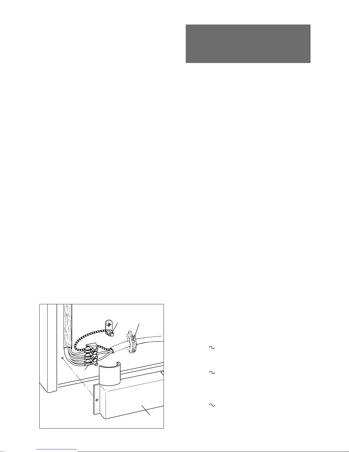
CONNECTING FEEDER CABLE
To connect the feeder cable to the cooker it is necessary to:
– Remove the screw that hold shield
“A” behind the oven (fig. 12.1).
– Insert the feeder cable of the suitable
section (see Feeder Cable Section)
into the cable clamp “D”.
– Connect the phase cables to terminal
“B”.
– Pull the feeder cable and block it with
cable clamp “D”.
– Re-mount shield “A”.
FEEDER CABLE SPECIFICATIONS
TYPE HO5RR-F
Cookers without heating
elements/plates:
230 V 3 x 0,75 mm
2
Cookers with electric oven:
230 V 3 x 1,5 mm
2
Cookers with 1 electric plate and
electric oven:
230 V 3 x 2,5 mm
2
Fig. 12.1
D
B
A
E
Before effecting any intervention on
the electrical parts of the appliance,
the connection to the network must
be interrupted.
Page 34
34
REPLACEMENTOF THE OVEN AND
GRILL ELEMENTS
The substitution of the electrical elements of the oven and the grill is done
in the following way:
– Dismount the back panel of the apli-
ance
– Unhook the electrical connections of
the broken elements
– Unscrew the screws that fasten the
element
– Remove the element from the inside of
the muffle. For the lower element lift
the bottom entrance of the oven
– Effect the substitution
– Re-mount, being particularly careful of
the grounder of all of the electrical
components.
REPAIRS
Before effecting any intervention
on the electrical parts of the appliance, the connection to the network must be interrupted.
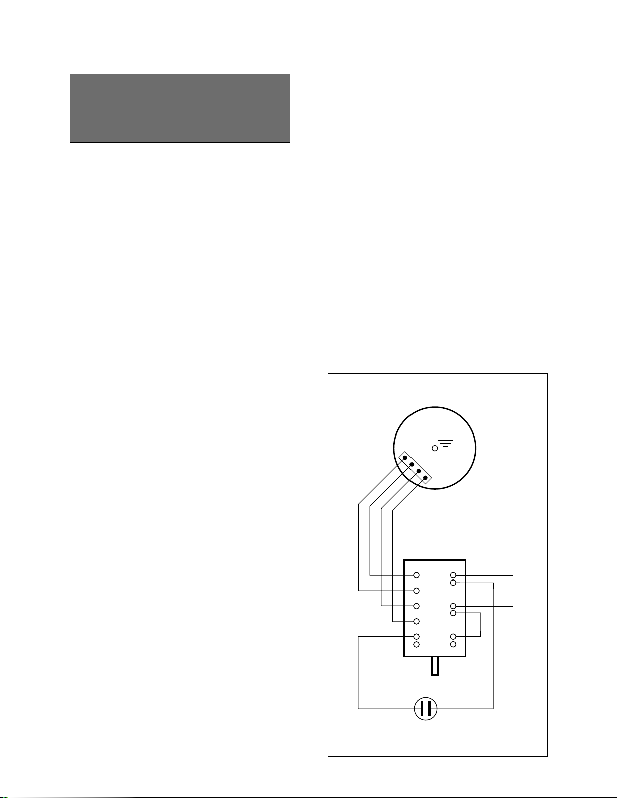
P3
P1
P2
5
2
1
3
4
3412
P
N
Fig. 12.4
REMPLACEMENT OF ELECTRICAL
COMPONENTS SITUATED UNDER
THE COOKTOP
Switches and thermostats, igniter and
electrodes can be replaced after lifting
the cooktop, following the instructions
shown in the chapter “REPLACEMENT
OF THE INJECTORS OF THE TOP
BURNERS”.
Page 35

35
Identification label
Page 36
Cod. 1102515 - ß2
Descriptions and illustrations in this
booklet are given as simply indicative.
The manufacturer reserves the right,
considering the characteristics of the
models described here, at any time and
without notice, to make eventual necessary modifications for their construction
or for commercial needs.
 Loading...