

Elba E74-200, E74-300, E74-301, E74-201, E74-210 Instructions For Use - Installation Advice
...Page 1
Built-in hobs
Tables encastrables
Instructions for the use - Installation advices
Mode d’emploi - Conseils pour l’installateur
Page 2

2
ENGLISH
Instructions for the use - Installation advices
Page 3
The manufacturer cannot be held re spon sible for possible inaccuracies due to printing or transcription errors in
the present booklet.
The manufacturer re serves the right to make all modifications to its products deemed necessary for manufacture
or commercial reasons at any moment and without prior notice, without jeopardising the es sential functional and
safety characteristics of the appliances.
FRANÇAIS
Mode d’emploi - Conseils pour l’installation
Page
31
Le fabricant n’est pas responsable des erreurs éventuelles, dues à des fautes de frappe ou d’impression, susceptibles de se trouver dans cette notice.
Il se réserve le droit, sans porter préjudice aux caractéristiques essentielles, du point de vue fonctionnel et du
point de vue sécurité, d’apporter à ses produits, à tout moment et sans préavis, toutes les modifications éventuellement nécessaires pour faire face à des exigences de fabrication ou de commercialisation.
Page 3

3
Instructions for the use
ENGLISH
Dear Customer,
Thank you for having purchased and given your
preference to our product.
The safety precautions and recommendations given below
are for your own safety and for others’. This manual will
also provide the necessary information to make full use of
the features offered by your appliance.
Please keep this booklet carefully. It may be useful in
future, either to yourself or to others if doubts should arise
relating to its use or operation.
This appliance must be used only for the task it has
explicitly been designed for, that is for cooking foods.
Any other form of usage is to be considered as
inappropriate and therefore dangerous.
The manufacturer declines all responsibility in the
event of damage caused by improper, incorrect or
unreasonable use of the appliance.
IMPORTANT PRECAUTIONS AND RECOMMENDATIONS FOR
USE OF ELECTRICAL APPLIANCES
Use of any electrical appliance implies the necessity to follow a series of fundamental rules.
In particular:
✓
Never touch the appliance with wet hands or feet;
✓
Do not operate the appliance barefooted;
✓
Do not allow children or disabled people to use the appliance without your supervision.
The manufacturer cannot be held responsible for any damages caused by improper, incorrect
or unreasonable use of the appliance.
Page 4

4
IMPORTANT PRECAUTIONS AND RECOMMENDATIONS
✓
After having unpacked the appliance, check to ensure that it is not damaged.
If you have any doubts, do not use it and consult your supplier or a professionally
qualified technician.
✓
Packing elements (i.e. plastic bags, polystyrene foam, nails, packing straps, etc.)
should not be left around within easy reach of children, as these may cause serious
injuries.
✓
The packaging material is recyclable and is marked with the recycling symbol
.
✓
Do not attempt to modify the technical characteristics of the appliance as this may
become dangerous to use.
✓
The appliance was designed for non-professional use by private individuals in communal dwellings.
✓
The manufacturer cannot be considered responsible for damage caused by unreasonable, incorrect or rash use of the appliance.
✓
If you should decide not to use this appliance any longer (or decide to substitute an
older model), before disposing of it, it is recommended that it be made inoperative in
an appropriate manner in accordance to health and environmental protection regulations, ensuring in particular that all potentially hazardous parts be made harmless,
especially in relation to children who could play with old appliances.
✓
The appliance should be installed and all the gas/electrical connections made by a
qualified engineer in compliance with local regulations in force and following the manufacturer's instructions.
TIPS FOR THE USER
✓ During and after use of the cooktop, certain parts will become very hot. Do not touch
hot parts.
✓ Keep children away from the cooking hob when it is in use.
✓ After use, ensure that the knobs are in position ● (off), and close the main gas delivery
valve or the gas cylinder valve.
✓ When the appliance is not being used, it is advisable to keep the gas tap closed.
✓ The periodic lubrication of the gas taps must be done only by specialized personnel.
In case of difficulty in the gas taps operation, call Service.
✓ Make sure that the electrical cables of other appliances installed nearby cannot come
into contact with the cooktop.
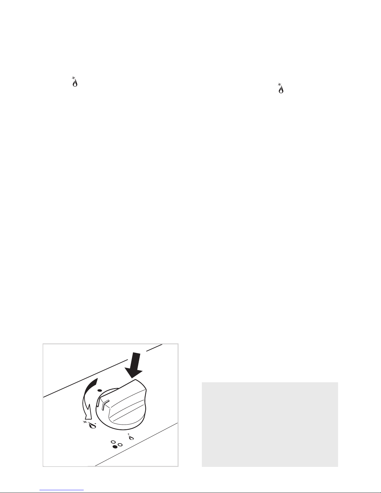
CAUTION:
If the burner is accidentally extinguished, turn the gas off at the control knob and wait
at least 1 minute before attempting to relight.
CAUTION:
Gas hobs produce heat and humidity in the environment in which they are installed.
Ensure that the cooking area is well ventilated by opening the natural ventilation
grilles or by installing an extractor hood connected to an outlet duct.
CAUTION:
If the hob is used for a prolonged time it may be necessary to provide further ventilation by opening a window or by increasing the suction power of the extractor hood (if
fitted).
Page 5
5
Fig. 1.1
FEATURES
1
1
mod. E74-200 ..
with safety valve
mod. E74-201 ..
without safety valve
“2 GAS” COOKING HOB (Fig. 1.1)
COOKING SPOTS
(Fig. 1.1)
1. Semirapid burner (SR) - 1,75 kW
2. Triple ring burner
(TR) - 3,50 kW
CONTROL PANEL DESCRIPTION
3. Burner 2 (TR) control knob
4. Burner 1 (SR) control knob
NOTE:
The model E74-200 .. has a safety valve system fitted. The flow of gas will be stopped if
and when the flame should accidentally go out.
All the appliances are fitted with an automatic ignition switch incorporated into the knob.
Page 6
6
“3 GAS” COOKING HOB (Fig. 1.2)
COOKING SPOTS
1. Semirapid burner (SR) - 1,75 kW
2. Auxiliary burner (A) - 1,00 kW
3. Triple ring burner
(TR) - 3,50 kW
CONTROL PANEL DESCRIPTION
4. Burner 3 (TR) control knob
5. Burner 2 (A) control knob
6. Burner 1 (SR) control knob
Fig. 1.2
mod. E74-300 ..
with safety valve
mod. E74-301 ..
without safety valve
NOTE:
The model E74-300 .. has a safety valve system fitted. The flow of gas will be stopped if
and when the flame should accidentally go out.
All the appliances are fitted with an automatic ignition switch incorporated into the knob.
Page 7
7
“2 GAS + 1 ELECTRIC PLATE” COOKING HOB (Fig. 1.3)
COOKING SPOTS
1. Semirapid burner (SR) - 1,75 kW
2. Rapid electric plate Ø 145 - 1500 W
3. Triple ring burner
(TR) - 3,50 kW
CONTROL PANEL DESCRIPTION
4. Burner 3 (TR) control knob
5. Electric plate 2 control knob
6. Burner 1 (SR) control knob
7. Electrical plate indicator light
Fig. 1.3
mod. E74-210 ..
with safety valve
mod. E74-211 ..
without safety valve
NOTE:
The model E74-210 .. has a safety valve system fitted. The flow of gas will be stopped if
and when the flame should accidentally go out.
All the appliances are fitted with an automatic ignition switch incorporated into the knob.
Page 8

8
GAS BURNERS
2
2
Fig. 2.1a
Fig. 2.1b
GAS BURNERS
The gas flow to the burners is achieved
by turning the knob (illustrated in figs.
2.1a - 2.1b) which controls the safety
tap.
By turning the knob so that the indicator
line points at the symbols printed on the
panel we obtain the following settings:
✓ full circle
● = closed valve
✓ symbol = maximum
aperture or flow
✓ symbol = minimum
aperture or flow
✓ To reduce the gas flow to minimum,
rotate the knob further anti-clockwise
to point the indicator towards the
small flame symbol.
✓ The maximum aperture position per-
mits rapid boiling of liquids, whereas
the minimum aperture position allows
slower warming of food or maintaining boiling conditions of liquids.
✓ Other intermediate operating adjust-
ments can be achieved by positioning
the indicator between the maximum
and minimum aperture positions, and
never between the maximum aperture and closed positions.
Models without safety cut-off valves
Models with safety cut-off valves
N.B. When the cooker top is not
being used, set the gas knobs to
their closed positions and also
close the cock valve on the gas
bottle or the main gas supply line.
Page 9
9
Fig. 2.2
LIGHTING GAS BURNERS
Models without
safety valve device
To light one of the gas burners, push in
and turn the relative knob to the maximum aperture position (large flame
symbol fig. 2.1a) and hold the knob
in until the flame has been lit.
Turn the gas tap to the position
required.
Note: Whenever special conditions of
the gas supplied locally make it difficult
to light the burner with the knob in the
maximum flow position, repeat the
operation with the knob in the minimum
flow position.
LIGHTING GAS BURNERS
Models with
safety valve device
In order to light the burner, you must:
1 – Turn the knob fig. 2.2 in anti-clock-
wise direction up to the maximum
aperture (symbol fig. 2.1b), push
in and hold the knob; this will light
the gas.
In case of black-out, bring
a lighted match close to the burner.
2 – Wait about ten seconds after the
gas lighting before releasing the
knob (starting time for the valve).
3 – Adjust the gas valve to the desired
power.
If the burner flame should go out for
some reason, the safety valve will automatically stop the gas flow.
To re-light the burner, return the knob to
the closed
● position, wait for at least
1 minute and then repeat the lighting
procedure.
If your local gas supply makes it difficult
to light the burner with the knob set to
maximum, set the knob to minimum and
repeat the operation.
The igni tion device shall not be
operated for more than 15 seconds.
If after 15 seconds the burner has
not lit, stop operating the device
and open the compartment door of
the cabinet underneath (if available)
and/or wait at least 1 minute before
attempting a further ignition of the
burner.
In case of black-out, bring a lighted
match close to the burner.
Page 10

10
CHOICE OF BURNER (fig. 2.3)
The symbols printed on the panel beside
the knobs indicate the correspondence
between the knob and the burner.
The most suitable burner is to be chosen
according to the diameter and volume
capacity of the container to be heated.
It is important that the diameter of the
pots or pans suitably match the heating
potential of the burners in order not to
jeopardise their efficiency and avoid a
waste of energy.
A small diameter pot or pan placed on a
large burner does not necessarily mean
that boiling conditions are reached
quicker.
Caution!
the cooking hob becomes very
hot during operation.
Keep children well out of reach.
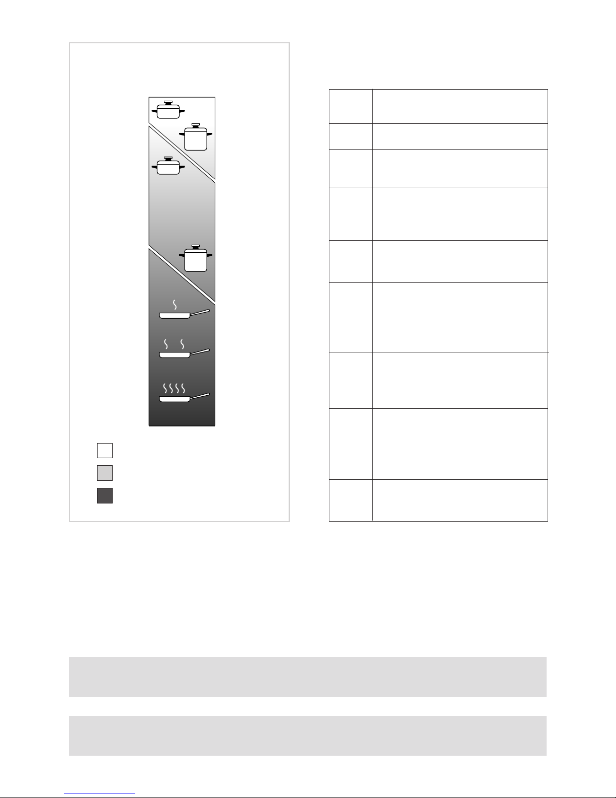
DIAMETERS OF PANS WHICH MAY BE USED
ON THE HOB
BURNERS MINIMUM MAX.
Auxiliary 12 cm 14 cm
Semirapid 16 cm 24 cm
Triple ring 26 cm 28 cm
wok max 36 cm
Fig. 2.3
Page 11

11
SPECIAL WOK GRILLE
(figs. 2.4, 2.5)
This special grille for woks should be placed over the pan-rest for the triple ring burner.
Warning:
✓ Using woks without this special grille may cause the burner to malfunction.
✓ Do not use the grille for ordinary, flat-bottomed saucepans.
IMPORTANT:
The special grille for wok pans (figs. 2.4 - 2.5) MUST BE PLACED ONLY over the panrest for the triple-ring burner.
Fig. 2.4
WRONG
Fig. 2.5
CORRECT
Page 12

12
ELECTRIC PLATES
3
3
1
2
3
4
5
6
Fig. 3.1
RAPID HOTPLATE (red dot)
The characteristics of this hotplate,
which is also equipped with a thermostatic cut-off device, make it possible to:
– achieve the cooking temperature
rapidly
– make full use of its output power
using flat-bottomed pans
– limit the output power with unsuitable
saucepans.
To turn on the electric hotplate, rotate
the knob (fig. 3.1) on the desired setting.
The numbers from 1 to 6 indicate the
operating positions with increasing
value, corresponding to higher temperatures.
When the pot contents come to the boil,
turn the heat down to the level desired.
Remember that the hotplate will continue to produce heat for about five minutes after it has been turned off.
PROPER USE OF THE ELECTRIC HOTPLATE
(fig. 3.2)
While using the electric hotplate, you
must:
✓ avoid using it without any vessel;
✓ avoid pouring liquids on it while it is
hot;
✓ use flat-bottomed (electric hotplate
type) pots and pans only;
✓ use cookware which covers as much
as possible surface of the hotplate;
✓ save electricity, by using lids whenev-
er possible;
✓ never cook food directly on the hot-
plate: always use a pan or a suitable
container.
An indicator light located on the control
panel signals that the hotplate is operating.
Fig. 3.2
Page 13
13
Hob controlled by 7-position
switch 0 - 6
1
2
3
4
5
6
Fig. 3.3
= Warming
= Cooking
= Roasting - Frying
ELECTRIC HOTPLATE USAGE
TABLE
Type of cooking
Switched OFF
For melting operations (butter
or chocolate)
To keep foods warm or heat
small quantities of water.
To heat greater quantities of
water and to whip creams
and sauces.
Slow boiling, e.g. spaghetti,
soups, boiled meats, to continue steam heating of roast
meats and stews.
For all kinds of fried foods,
steaks, cutlets and cooking
without a lid.
For browning of meat,
cooked potatoes, fried fish
and for boiling large quantities of water.
Rapid frying, grilled steaks,
etc.
Position
of switch
0
1
2
3
2
3
4
4
4
5
6
Caution! the cooking hob becomes very hot during operation.
Keep children well out of reach.
Never cook food directly on the electric hotplates!
Always use a saucepan or special container.
Page 14

14
CLEANING AND MAINTENANCE
4
4
GENERAL ADVICE
✓ Before you b e g i n c l e a n i n g you
must ensure th a t t h e hob is
switched off.
✓ It is advisable to clean when the
appliance is cold and especially when
cleaning the enamelled parts.
✓ All enamelled surfaces have to be
washed with soapy water or some
other non-abrasive product with a
sponge and are to be dried preferably
with a soft cloth.
✓ Avoid leaving alkaline or acid sub-
stances (lemon juice, vinegar etc.) on
the surfaces.
✓ Do not use cleaning products with a
chlorine or acidic base.
WARNING
When correctly installed, your product meets all safety requirements laid
down for this type of product category. However special care should be
taken around the underneath of the
appliance as this area is not designed
or intended to be touched and may
contain sharp or rough edges, that
may cause injury.
ENAMELLED PARTS
✓ All the enamelled parts must be
cleaned with a sponge and soapy
water only or other non-abrasive
products.
✓ Dry preferably with a microfibre or
soft cloth.
If acid substances such as lemon
juice, tomato conserve, vinegar etc.
are left on the enamel for a long time
they will etch it, making it opaque.
STAINLESS STEEL ELEMENTS
✓ Stainless steel parts must be rinsed
with water and dried with a soft and
clean cloth.
✓ For persistent dirt, use specific non-
abrasive products available commercially or a little hot vinegar.
✓ Note: regular use could cause dis-
colouring around the b urners,
because of the high flame temperature.
ELECTRIC HOTPLATES
✓ Always clean when the hotplate is
tepid.
✓ Use a soft cloth, dampened with
water, and a little salt. To finish off,
use a soft cloth with a little oil.
CONTROL KNOB
✓ The control knobs may be removed
for cleaning but care should be taken
not to damage the seal.
Attention
The a p p liance g e t s ve r y h o t ,
mainly around the cooking areas.
It is very important that children
are not left alone in the kitchen
when you are cooking.
Do not use a steam cleaner
because the moisture can get
into the appliance thus make it
unsafe.
Page 15
15
GAS TAPS
✓ In the event of operating faults in the gas taps, call the Service Department
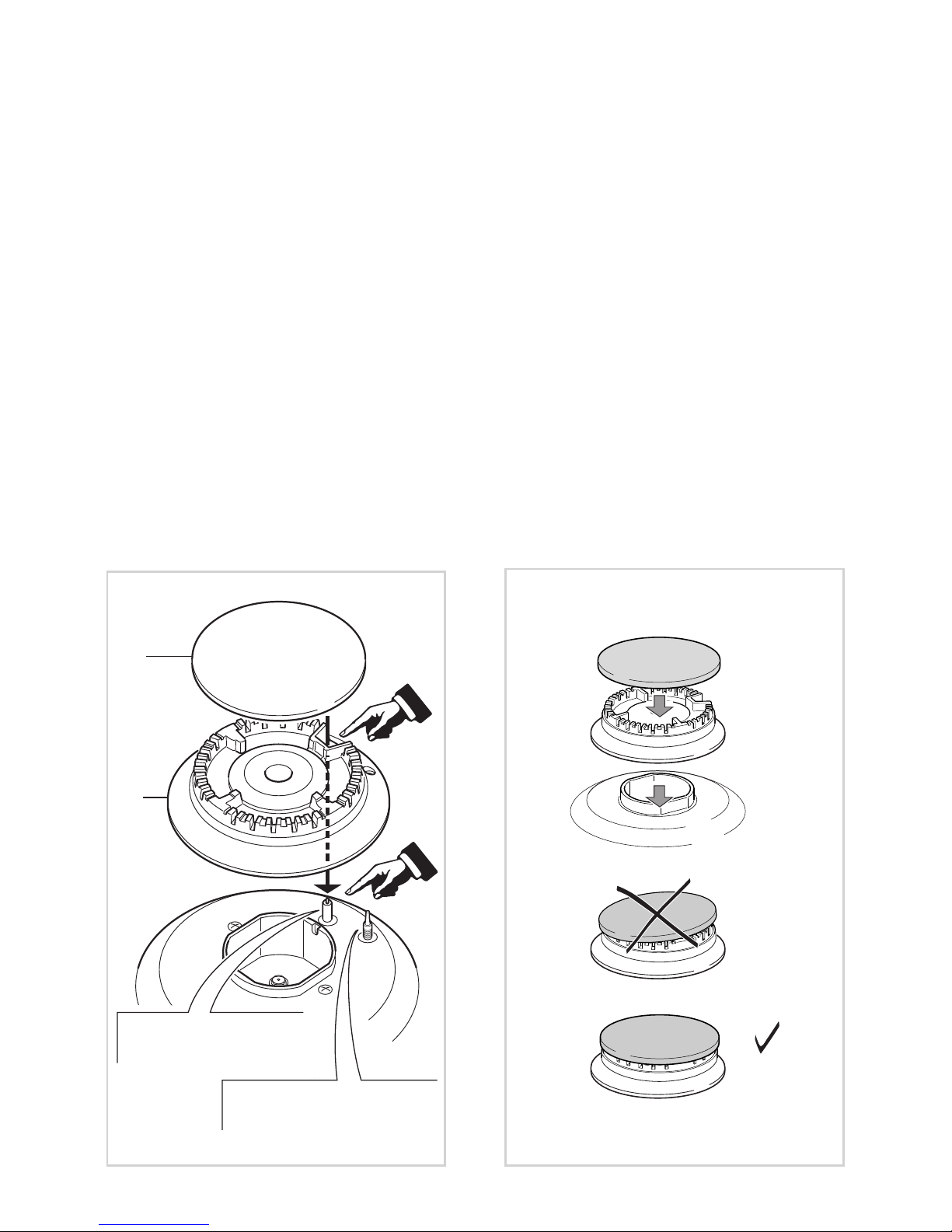
BURNERS AND GRIDS
✓ These parts can be removed and cleaned with appropriate products.
✓ After cleaning, the burners and their flame spreaders must be well dried and correctly
replaced.
✓ It is very important to check that the burner flame spreader and the cap have been
correctly positioned. Failure to do so can cause serious problems.
✓ In the models with safety device, check that the probe next to each burner is always
clean to ensure correct operation of the safety valves.
✓ In appliances with electric ignition keep the electrode clean so that the sparks always
strike.
✓ Note: To avoid damage to the electric ignition do not use it when the burners are
not in place.
Fig. 4.2
Fig. 4.1
F
C
Ignitor “S”
(some models only)
Flame failure probe “T”
(some models only)
Page 16
16
CORRECT REPLACEMENT OF THE BURNERS
It is very important to check that the burner flame spreader F and the cap C have
been correctly positioned (see figs. 4.1 and 4.2).
Failure to do so can cause serious problems.
In appliances with electric ignition, check that the electrode S (fig. 4.1) is always clean to
ensure trouble-free sparking.
In the models with safety device, check that the probe T (fig. 4.1) next to each burner
is always clean to ensure correct operation of the safety valves.
Both the probe and ignition plug must be very carefully cleaned.
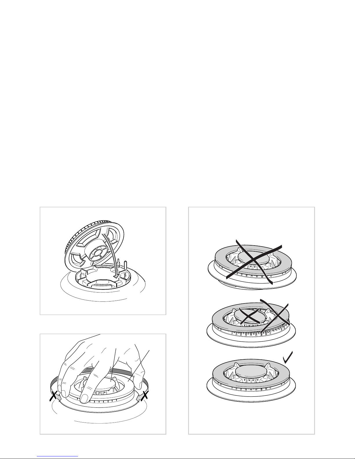
CORRECT POSITION OF TRIPLE RING BURNER
The triple ring burner must be correctly positioned (see fig. 4.3); the burner rib must be
fitted in their housing as shown by the arrow.
The burner correctly positioned must not rotate (fig. 4.4).
Then position the cap A and the ring B (fig. 4.4 - 4.5).
Fig. 4.5
Fig. 4.3
Fig. 4.4
A
B
Page 17

17
IMPORTANT
✓ The appliance should be installed, regulated and adapted to function by a QUALI-
FIED INSTALLATION TECHNICIAN.
Failure to comply with this condition will render the guarantee invalid.
✓ The appliance must be installed in compliance with regulations in force and following
the manufacturer's instructions.
✓ Installation technicians must comply to current laws in force concerning ventilation
and the evacuation of exhaust gases.
✓ Always unplug the appliance before carrying out any maintenance operations or
repairs.
✓
The appliance must be housed in heat-resistant units.
✓
These tops are designed to be embedded into kitchen fixtures measuring 600
mm in depth.
✓
The walls of the units must not be higher than work top and must be
capable of resisting temperatures of 75 °C above room temperature.
✓
Do not instal the appliance near inflammable materials (eg. curtains).
WARNING
When correctly installed, your product meets all safety requirements laid down
for this type of product category.
However special care should be taken around the underneath of the appliance
as this area is not designed or intended to be touched and may contain sharp
or rough edges, that may cause injury.
Installation
advice
Page 18
18
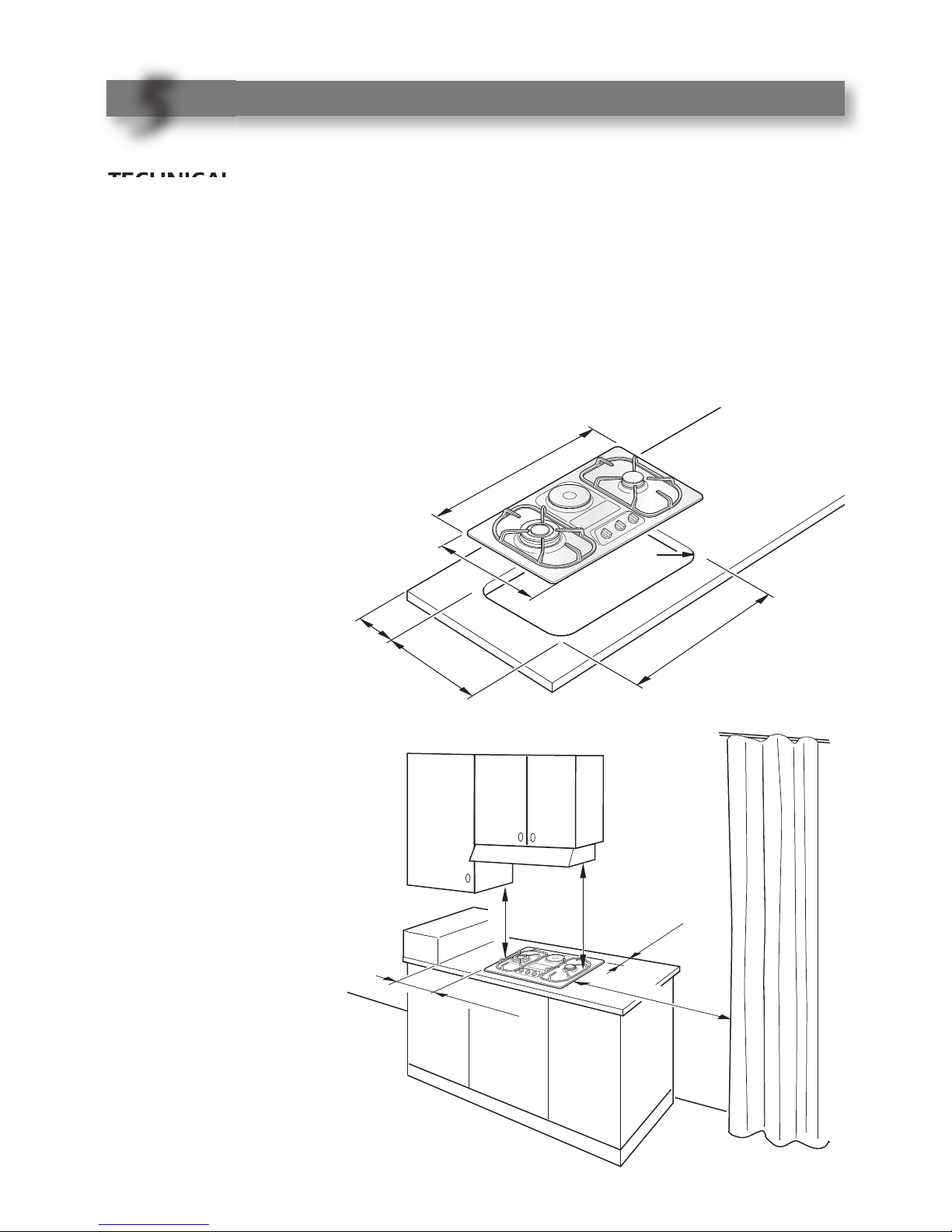
500
mm
450 mm
5
0
m
m
m
in
200 mm
min
650 mm
Fig. 5.2
TECHNICAL INFORMATION FOR THE INSTALLER
Before installing the hob, remove the protective film.
This hob may be built into a worktop of 30 to 40 mm thick and 600 mm deep.
In order to install the hob into the kitchen cabinet, an aperture with the dimensions
shown in fig. 5.1 has to be made, keeping in consideration the following:
✓ inside the cabinet, between the bottom side of the hob and the upper surface of any
other appliance or internal shelf there must be a clearance of at least 30 mm;
✓ the hob must be installed no less than 200 mm away from any side wall;
430
6
0
m
in
410
730
R
=
70
7
1
0
Fig. 5.1
INSTALLATION
5
5
✓ the hob must be
installed at a distance of
no less than 50 mm
from the rear wall.
✓ there must be a dis-
tance of at least 650
mm between the hob
and any wall cabinet or
extractor hood positioned immediately
above (see fig. 5.2)
✓ the coatings of the walls
of the unit or appliances
near the hob must be
heat resistant.
Do not install the appliance near inflammable
materials (eg. curtains).
Page 19

19
30 mm
Fig. 5.3
Space for
connections
Clearance
Cupboard
door
CUPBOARD DOORS (fig. 5.3)
It is recommended that a 30 mm clearance be left between the hob and the
partition surface underneath.
30 mm
Fig. 5.4
A
B
D
FASTENING THE COOKTOP
(fig. 5.4 - 5.5)
Each hob is supplied with a set of tabs
and screws to fasten it on units with a
worktop 3 to 4 cm deep.
The kit includes 4 tabs “A” and 4 selftapping screws “B”.
✓ Cut the unit.
✓ Stretch gasket “D” over the edge of
the hole made, being careful to overlay the junction edges
✓ Turn the hob over and put tabs “A”
(fig. 5.4 - 5.5) into the housings, only
tighten screws “B” a few turns.
Make sure that the tabs are mounted
correctly as shown in the figure 5.4 -
5.5. Turn the tabs so that the cooktop
can be dropped into the aperture.
✓ Lay the hob into the aperture of the
unit and position it correctly.
✓ Put tabs “A”; into place, tooth “C” of
the tabs should go into the hole.
✓ Tighten screws “B” until the hob is
completely secured.
✓ Using a sharp tool cut off the part of
gasket “D” which protrudes from the
cooktop. Take care not to damage the
benchtop.
C
40 mm
A
B
DC
Fig. 5.5
Page 20

20
CHOOSING SUITABLE
SURROUNDINGS
(for gas models)
The room where the gas appliance is to
be installed must have a natural flow of
air so that the gas can burn (in compliance with the current laws in force).
The flow of air must come directly from
one or more openings made in the
outside walls with a free area of at least
100 cm
2
.
If the appliance does not have a noflame safety device this opening must
have an area of at least 200 cm
2
.
The openings should be near the floor
and preferably on the side opposite the
exhaust for combustion products and
must be so made that they cannot be
blocked from either outside or inside.
When these openings cannot be made,
the necessary air can come from an
adjacent room which is ventilated as
required, as long as it is not a bedroom
or a danger area (in compliance with the
current laws in force).
In this case, the kitchen door must allow
the passage of the air.
DISCHARGING PRODUCTS
OF COMBUSTION
Extractor hoods connected directly to
the outside must be provided, to allow
the products of combustion of the gas
appliance to be discharged (fig. 5.6).
If this is not possible, an electric fan may
be used, attached to the external wall or
the window; the fan should have a
capacity to circulate air at an hourly rate
of 3-5 times the total volume of the
kitchen (fig. 5.7).
The fan can only be installed if the room
has suitable vents to allow air to enter,
as described under the heading
“Choosing suitable surroundings” (in
compliance with the current laws in
force).
H min 650 mm
Fig. 5.6
Air vent
Extractor hood for
products of
combustion
Fig. 5.7
Air vent
Electric fan to
extract products of
combustion
Installation technicians must comply
to current laws in force concerning
venti l ation and the evacua t ion of
exhaust gases.
Inte nsive and prolo nged u se may
require extra ventilation, e.g. opening
a window, or more efficient ventilation increasing the mechanical suction power if this is fitted.
Page 21

21
GAS SECTION
6
6
GAS INSTALLATION REQUIREMENTS
Important !
✓
Before installation, make sure that the local distribution conditions (gas type and pressure) and the adjustment of this appliance are compatible. The appliance adjustment
conditions are given on the plate or the label.
✓
This appliance must be installed and serviced only by a suitably qualified, registered
installer with technical knowledge of both gas installation and electricity. The installation or service must comply with the current editions of the applicable standards, regulations, and codes of practice governing gas and electrical installations.
✓
Failure to install the appliance correctly could invalidate any manufacturer’s warranty.
This appliance is supplied for use on NATURAL GAS or LPG (check the gas regulation
label attached on the appliance).
✓ Appliances supplied for use on NATURAL GAS: they are adjusted for this gas only
and cannot be used on any other gas (LPG) without modification. The appliances are
manufactured for conversion to LPG.
✓ Appliances supplied for use on LPG: they are adjusted for this gas only and cannot be
used on any other gas (NATURAL GAS) without modification. The appliances are
manufactured for conversion to NATURAL GAS.
If the NATURAL GAS/LPG conversion kit is not supplied with the appliance this kit can
be purchased by contacting the After-Sales Service.
Page 22

22
CONNECTING THE COOKTOP TO THE GAS SUPPLY
The gas connection fitting (Figs. 6.1-6.2) is made up of:
✓ the floating nut;
✓ the elbow;
✓ the gaskets;
✓ the hose holder for Natural gas or LPG - to be used for gas connection with a rubber
hose.
Imporant! A rubber hose connection shall only be made if permitted by the applica-
ble local regulations.
If the hose holder is not supplied with the appliance it can be purchased by contact-
ing the After-Sales Service.
The gas connection must be carried out by an authorised person according to the
relevant local standards.
✓ If using a flexible hose, make sure it does not come into contact with moving parts.
✓ The rear of the chassis is recessed to provide a channel for the appliance inlet pipe.
✓ The gas connection fitting can be turned in the direction required (but never in a verti-
cal or horizontal position) after loosening the elbow and floating nut connection.
✓ Never attempt to turn the elbow without having first loosened the floating nut.
✓ The supplied gaskets guarantee a good seal for the gas connection. We recommend
that you replace the gaskets on the slightest sign of wear, deformation or imperfection.
✓ After connecting to the gas mains, check that the couplings are correctly
sealed, using soapy solution, but never a naked flame.
Page 23

23
E
lbow
Gasket
F
loating nut
A
ppliance
inlet
p
ipe
Gasket
I
SO 228-1 (male)
1/2” G cylindrical
ISO 228-1 (male)
1
/2” G cylindrical
Hose holder
for LPG only
Hose holder
for Natural gas only
Hose clamp
(not supplied)
Rubber hose
(not supplied)
for LPG connection
(internal diameter 6 mm)
Hose clamp
(not supplied)
Rubber hose (not supplied)
for Natural gas connection
(internal diameter 15 mm)
Fig. 6.1
Gas connection with a rubber hose
Rigid pipe
(not supplied)
Flexible hose
(not supplied)
Elbow
Gasket
Floating nut
Appliance
inlet
pipe
Gasket
ISO 228-1 (male)
1/2” G cylindrical
ISO 228-1 (male)
1/2” G cylindrical
Fig. 6.2
Gas connection with rigid pipes or a flexible pipe
Page 24

24
ADDITIONAL GAS CONNECTION REQUIREMENTS
When connecting the cooktop to the gas supply with a rubber hose, make sure that:
✓ If not already fitted, you fit the Natural gas or LPG hose holder on the inlet pipe, mak-
ing sure that you place the sealing washer between them (as shown in Fig. 6.1). If the
hose holder is not supplied with the appliance it can be purchased by contacting the
After-Sales Service.
✓ You connect the cooktop to the gas supply using a suitable rubber hose (internal
diameter 15 mm for Natural gas or internal diameter 6 mm for LPG). The hose must
comply with the applicable local regulations and be of the correct construction for the
type of gas being used.
✓ You make sure that the hose is tightly and securely fitted at both ends.
✓ You use a standard hose clamp (not supplied) to fasten the hose.
✓ The hose is as short as possible, without twists or kinks.
✓ The hose is not longer than 750 mm (or refer to applicable local regulations) and does
not come into contact with sharp edges, corners or moving parts.
✓ The hose is not under tension, twisted, kinked or too sharply bent.
✓ The hose does not come into contact with any part of the cooktop with a surface tem-
perature of 70°C or above
✓ The hose can easily be inspected along its entire length to check its condition.
✓ The hose is replaced at the printed due date or if it shows signs of wear or damage,
and replaced regardless of its condition after a maximum of three years.
✓ You inform the customer that the hose should not be subjected to corrosion by acidic
cleaning agents.
When connecting the cooktop to the gas supply with rigid pipes or a flexible hose,
make sure that:
✓ You use rigid pipes or a flexible hose compliant with applicable local regulations. The
flexible hose shall be of the correct construction for the type of gas being used and of
the correct size to maintain the heat output of the appliance.
✓ The connection with rigid metal pipes does not cause stress or pressure to the gas piping.
✓ The flexible hose is not under tension, twisted, kinked, or too tightly bent, neither
while the cooktop is in use nor while it is being connected or disconnected.
✓ The flexible hose is not longer than 2000 mm (or refer to applicable local regulations)
and does not come into contact with sharp edges, corners, or moving parts, as these
may cause abrasion. Use a single flexible hose only; never connect the cooktop with
more than one flexible hose.
✓ The flexible hose can easily be inspected along its entire length to check its condition;
if it has an expiry date, it should be replaced before that date.
✓ If using a flexible hose which is not entirely made of metal, make sure that it does not
come into contact with any part of the cooktop with a surface temperature of 70°C or
above
(or refer to applicable local regulations).
✓ The rigid pipe or flexible hose is replaced if it shows signs of damage.
✓ The flexible hose is not subject to excessive heat by direct exposure to flue products
or by contact with hot surfaces.
✓ The socket into which the plug of the flexible hose fit is permanently attached to a firmly
fixed gas installation pipe and is positioned so that the hose hangs freely downwards.
✓ The plug of the flexible hose is accessible after installation, so that it can be discon-
nected for service or removal.
✓ You inform the customer that the rigid pipe or flexible hose should not be subjected
to corrosion by cleaning agents.
(or refer to applicable local regulations).
Page 25

25
ADAPTING THE APPLIANCE TO FUNCTION WITH DIFFERENT
TYPES OF GAS
If a different gas from that one indicated on the label is used, you need to adapt the cooktop
to this new situation.
If the injectors are not supplied they can be obtained from the “Service
Centre”.
Select the injectors to be replaced according to the table on next page.
The nozzle diameters, expressed in hundredths of a millimetre, are marked on the body
of each injector.
OPERATIONS TO BE PERFORMED WHEN SUBSTITUTING
THE INJECTORS
✓ Remove the pan-supports and the burner covers;
✓ Using a wrench substitute the injectors “J” (Figs. 6.3 - 6.4) with those ones suitable for
the type of gas for which it is to be used.
The burners are conceived in such a way so as not to require the adjustment of the
primary air.
Fig. 6.4
J
Fig. 6.3
J
Page 26

26
TABLE FOR THE CHOICE OF THE INJECTORS
Cat: II 2H 3+
AIR VENT NECESSARY FOR GAS COMBUSTION = (2 m
3
/h x kW)
BURNERS
Air necessary for combustion [m3/h]
Auxiliary (A) 2,00
Semi-rapid (SR) 3,50
Triple ring (TR) 7,00
G30/G31
28-30/37 mbar
G 20
20 mbar
BURNERS
Nominal
Power
[Hs - kW]
Reduced
Power
[Hs - kW]
Ø injector
[1/100 mm]
Ø injector
[1/100 mm]
Auxiliary (A) 1,00 0,30 50 72 (X)
Semi-rapid (SR) 1,75 0,45 65 97 (Z)
Triple ring (TR) 3,50 1,50 95 135 (T)
Page 27

27
Fig. 6.5
Fig. 6.6
A
REGULATING THE BURNER
MINIMUM SETTING
When switching from one type of gas to
another, the minimum flow rate must be
also calibrated. The flame should not go
out even when passing suddenly from
maximum to minimum flame.
To regulate the flame follow the instructions below:
– Light the burner.
– Set the gas tap to minimum.
– Remove the tap knob.
For gas taps provided with adjustment screw in the centre of the shaft
(fig. 6.5):
– Using a screwdriver with max. diame-
ter 3 mm, turn the screw inside the tap
until the correct setting is obtained.
For gas taps provided with adjustment
screw on the body
(fig. 6.6):
– Turn the screw “A” to the correct set-
ting with a screwdriver.
For G30/G31 gas, tighten the adjustment screw completely.
LUBRICATING THE GAS TAPS
If one of the gas taps becomes hard to
turn, dismantle it, thoroughly clean with
petrol and apply special high-temperature grease.
Warning!
These operations must be performed by
a specialised engineer.
Page 28

28
ELECTRICAL SECTION
7
7
IMPORTANT: Installation has to be
carried out according to the instructions provided by the manufacturer.
Incorrect installation might cause
harm and damage to people, animals or objects, for which the manufacturer accepts no responsibility.
DETAILS
✓ Connection to the electric power sup-
ply must be carried out by a qualified
technician and following the appropriate safety regulations.
✓ Before carrying out the connection to
the power supply, the voltage rating
of the appliance (indicated on the
appliance rating plate) must be
checked for correspondence to the
available mains supply voltage, and
the mains electric wiring should be
capable of bearing the hob power rating (also indicated on the rating plate).
✓ The appliance is supplied without a
power supply plug and therefore if
you are not connecting directly to the
mains, a standardized plug suitable
for the load must be fitted (gas models only).
✓ The power supply must be connected
to a suitable earth wiring, in conformity to current safety regulations.
✓ The colours of the wires in the hob
power cable may not correspond with
the colours marked on the terminals
of your electrical plug. The plug
should in any case be wired as follows:
– connect the green/yellow wire to the
terminal marked with the letter PE or
the earth symbol or coloured
green/yellow;
– connect the blue wire to the terminal
marked with the letter N or coloured
black;
✓ It is possible to connect the appliance
directly to the mains by means of a
heavy duty switch with 3 mm minimum distance between the contacts.
✓ The power supply cord must not
touch against any hot surfaces and
must be placed so that its temperature does not exceed 75°C at any
point along its length.
✓ After having installed the appliance,
the power switch or power plug must
always be in an accessible position.
✓ The appliance must have its own
supply; any other appliances installed
near it must be supplied separately.
–
N.B. For con nection to the mains
power supply, never use adaptors,
reductions or multiple power points
as these may overheat and catch fire.
In the event that installation should
require modifications to the mains supply wiring system or if the power plug is
not suitable for the type of power point
available, it is recommended that a qualified technician be called to carry out
substitution.
The technician will also have to verify
that the cross-section of the electric
cables on the power point match the
appliance’s power rating.
– connect the brown wire to the ter-
minal marked with the letter L or
coloured red.
Connection to a good earth wiring
system is absolutely essential.
The manufacturer accepts no
respo nsibility for any inconvenience caused by failure to comply
with this rule.
Page 29

29
FEEDER SPECIAL CABLE
SECTION Type “HO5RR-F”
✓ Cooking hobs 2 GAS and 3 GAS
220-240 VAC 50/60 Hz 3 x 0,75 mm
2
✓ Cooking hob 2 GAS + 1 ELECTRIC
220-240 VAC 50/60 Hz 3 x 1,5 mm
2
WARNING: If the power supply cable is damaged, it must be replaced only by an
authorised service agent in order to avoid a hazard.
REPLACING THE POWER
SUPPLY CABLE
✓
The cable must be replaced with a
cable of the same type.
✓
The electrical cable must be connected to the terminal block following the
diagrams of Fig. 7.1.
220-240 V ~
L1 N(L2)PE
Fig. 7.1
Page 30

30
Page 31

31
Mode d’emploi
FRANÇAIS
PRECAUTIONS POUR L’EMPLOI DES APPAREILS ELECTRIQUES
Pour utiliser un appareil électrique, il faut respecter certaines règles fondamentales et,
en particulier:
✓ Ne pas toucher l’appareil avec des mains et des pieds mouillés ou humides;
✓ Ne pas utiliser l’appareil, les pieds nus;
✓ Ne pas laisser des enfants ou des handicapés utiliser l’appareil, sans surveillance;
Le fabricant ne peut être tenu pour responsable de dommages éventuels résultant d'un
usage impropre, erroné ou déraisonnable.
Cher Client
Vous venez d’acquérir une de nos tables de cuisson et nous
vous remercions de votre choix.
Celle-ci a été soigneusement conçue, fabriquée et testée
pour votre plus grande satisfaction. Pour être à même de
l’utiliser dans les meilleures conditions et pour obtenir ce que
vous êtes en droit d’en attendre, nous vous conseillons de lire
très attentivement cette notice d’utilisation.
Les instructions et les conseils qu’elle contient vous
aideront efficacement à découvrir toutes les qualités de votre
nouvel appareil.
Cet appareil est destiné uniquement à l’usage pour lequel
il a été expressément conçu, c’est-à-dire la cuisson
d’aliments. Tout autre usage est à considérer comme
impropre et donc dangereux.
Le fabricant décline toute responsabilité quant aux
dommages éventuels, résultant d'une utilisation impropre,
erronée ou déraisonnable de l’appareil.
Page 32

32
PRECAUTIONS ET CONSEILS IMPORTANTS
✓ Après avoir éliminé l’emballage, vérifier que l’appareil est en bon état. En cas de
doute, ne pas l’utiliser et s’adresser au fournisseur le plus proche ou à un technicien
qualifié.
✓ Les éléments de l’emballage (sacs en plastique, mousse, clous, feuillards, etc.) doi-
vent être laissés hors de portée des enfants, car ils constituent une source potentielle
de danger.
✓ L'emballage est composé de matériaux entièrement recyclables et porte le symbole
de recyclage .
✓ Ne pas essayer de modifier les caractéristiques techniques de l’appareil, car cela peut
être dangereux.
✓ Le constructeur ne peut être tenu pour responsable de dommages éventuels résultant
d'un usage impropre, erroné ou déraisonnable.
✓ Au cas où l’on déciderait de ne plus utiliser l’appareil (ou de remplacer un vieil appa-
reil par un nouveau), avant de le mettre au rebut, le rendre inutilisable, conformément
aux prescriptions en vigueur en matière de protection de la santé et de lutte contre la
pollution de l’environnement.
Rendre aussi inutilisables les parties susceptibles de constituer un danger, surtout
pour des enfants qui pourraient utiliser l’appareil hors d’usage comme jouet.
✓ L'installation et tous les branchements gaz/électriques doivent être effectués par un
technicien qualifié, dans le plein respect des normes de sécurité en vigueur et selon
les instructions du fabricant.
IMPORTANT :
En cas d’extinction accidentelle des flammes du brûleur, fermer le bouton de commande et attendre au moins une minute avant d’essayer de rallumer.
IMPORTANT :
L’utilisation d’un appareil de cuisson au gaz produit de la chaleur et de l’humidité
dans les locaux où celui-ci est installé.
Veiller à ce que le local soit bien aéré: garder les bouches de ventilation naturelle
ouvertes ou installer une hotte d’aspiration équipée d’un conduit d’évacuation.
IMPORTANT :
L’usage intensif et prolongé de cet appareil peut nécessiter une aération supplémentaire, comme par exemple l’ouverture d’une fenêtre, ou une aération plus efficace,
comme l’augmentation de la puissance d’aspiration mécanique s’il y en a une.
CONSEILS POUR L’UTILISATEUR
✓ Pendant et immédiatement après le fonctionnement certaines parties des tables de
cuisson atteignent des températures très élevées. Eviter de les toucher.
✓ Tenir les enfants éloignés de l'appareil, surtout lorsqu'il est en fonction.
✓ Après avoir utilisé la table de cuisson, vérifier que l'index des manettes est sur la posi-
tion de fermeture et fermer le robinet principal de la conduite d'alimentation en gaz ou
le robinet de la bonbonne.
✓ La lubrification périodique des robinets gaz doit être exclusivement effectuée par du
personnel spécialisé. En cas d'anomalies de fonctionnement des robinets gaz, appeler le Service Après-Vente.
✓ Vérifier que les fils électriques d’autres appareils, utilisés dans le voisinage, ne puis-
sent pas venir au contact de la table de cuisson.
Page 33

33
TABLE ENCASTRABLE “2 FEUX GAZ” (Fig. 1.1)
DESCRIPTION DES FEUX
(Fig. 1.1)
1. Brûleur semi-rapide (SR) - 1,75 kW
2. Super brûleur à triple couronne
(TC) - 3,50 kW
DESCRIPTION DES COMMANDES
3. Manette commande du brûleur 2 (TC)
4. Manette commande du brûleur 1 (SR)
CARACTERISTIQUES
1
1
Fig. 1.1
mod. E74-200 ..
avec système de sécurité
mod. E74-201 ..
sans système de sécurité
REMARQUE:
Le modèle E74-200 .. est équipé d’un système de sécurité. La sortie du gaz est bloquée,
si la flamme venait à s’éteindre accidentellement.
Le modèle est équipé d’allumage électronique incorporé dans les manettes.
Page 34

34
REMARQUE:
Le modèle E74-300 .. est équipé d’un système de sécurité. La sortie du gaz est bloquée,
si la flamme venait à s’éteindre accidentellement.
Le modèle est équipé d’allumage électronique incorporé dans les manettes.
TABLE ENCASTRABLE “3 FEUX GAZ” (Fig. 1.2)
DESCRIPTION DES FEUX
1. Brûleur semi-rapide (SR) - 1,75 kW
2. Brûleur auxiliaire (A) - 1,00 kW
3. Super brûleur à triple couronne
(TC) - 3,50 kW
DESCRIPTION DES COMMANDES
4. Manette commande du brûleur 3 (TC)
5. Manette commande du brûleur 2 (A)
6. Manette commande du brûleur 1 (SR)
Fig. 1.2
mod. E74-300 ..
avec système de sécurité
mod. E74-301 ..
sans système de sécurité
Page 35

35
TABLE ENCASTRABLE “2 FEUX GAZ + 1 PLAQUE ELECTRIQUE”
(Fig. 1.3)
DESCRIPTION DES FEUX
1. Brûleur semi-rapide (SR) - 1,75 kW
2. Plaque électrique rapide Ø 145 - 1500 W
3. Super brûleur à triple couronne (TC) - 3,50 kW
DESCRIPTION DES COMMANDES
4. Manette commande du brûleur 3 (TC)
5. Manette commande plaque électrique 2
6. Manette commande du brûleur 1 (SR)
7. Témoin fonctionnement plaque électrique
REMARQUE:
Le modèle E74-210 .. est équipé d’un système de sécurité. La sortie du gaz est bloquée,
si la flamme venait à s’éteindre accidentellement.
Le modèle est équipé d’allumage électronique incorporé dans les manettes.
Fig. 1.3
mod. E74-210 ..
avec système de sécurité
mod. E74-211 ..
sans système de sécurité
Page 36

36
BRULEURS A GAZ
2
2
BRULEURS A GAZ
L’arrivée du gaz dans les brûleurs est
commandée par le bouton illustré sur le
figs. 2.1a - 2.1b qui commande les robinets munis d’une fermeture de sûreté.
En faisant coïncider le symbole du bouton avec ceux qui se trouvent sur le
tableau, on obtient:
✓ disque plein
● = robinet fermé
✓ symbole = ouverture max.
ou débit max.
✓ symbole = ouverture min.
ou débit min.
✓ Pour obtenir un débit plus réduit,
continuer à faire tourner le bouton à
fond, jusqu’au symbole représentant
une petite flamme.
✓ Le débit maximum sert à faire bouillir
des liquides rapidement, tandis que
le débit réduit permet de faire
réchauffer quelque chose lentement
ou bien de maintenir la température
d’ébullition.
✓ Si de particulières conditions dues à
la distribution locale de gaz empèchaient l’allumage du brûleur quand
le bouton est en position de flux
maximal, il est conseillé de répéter
l’opération avec le bouton en position
de flux minimal.
N.B. Quand le plan de cuisson est
à l’arrêt, faire tourner le bouton des
robinets en position de fermeture
et fermer le robinet de la bonbonne
de gaz ou du tuyau d’alimentation
de gaz.
Fig. 2.1a
Fig. 2.1b
Modèles sans système de sécurité
Modèles avec système de sécurité
Page 37

37
Fig. 2.2
Ne jamais faire durer l’opération
d’allumage électronique plus de 15
secondes.
Dans le cas où le brûleur ne s'allumerait pas, attendre environ 1
minute avant de tenter de l'allumer
à nouveau.
ALLUMAGE ELECTRIQUE
DES BRULEURS
Modèles sans système de sécurité
Pour allumer l’un des brûleurs, appuyer
sur la manette correspondante (fig.
2.1a), et la faire tourner jusqu’à la position de débit maximum (grande flamme
); puis continuer à appuyer sur la
manette jusqu’à ce que l’allumage se
fasse (fig. 2.2).
En cas de coupure de courant électrique, approcher une flamme du brûleur.
Régler le robinet de gaz pour le mettre
dans la position voulue.
Note: Si des conditions locales particulières dans la distribution du gaz rendaient l’allumage du brûleur difficile
avec la manette en position débit maximum, il est conseillé de répéter l’opération avec la manette en position débit
minimum.
ALLUMAGE ELECTRIQUE
DES BRULEURS
Modèles avec système de sécurité
Pour allumer un brûleur:
1 – Faire tourner la manette du robinet
dans le sens contraire (fig. 2.2) des
aiguilles d’une montre, pour arriver
sur la position correspondant au
débit maximum (grande flamme ).
Appuyer sur la manette (fig. 2.1b) et
la maintenir appuyée, l’allumage
sera activé. En cas de coupure de
courant électrique, approcher une
flamme du brûleur.
2 – Attendre une dizaine de secondes
environ, une fois que le brûleur est
allumé, avant de relâcher la manette
(temps d’amorçage du clapet).
3 – Régler le robinet de gaz pour le
mettre dans la position voulue.
Si la flamme du brûleur s’éteint pour
une raison quelconque, le clapet de
sécurité interrompt automatiquement la
sortie du gaz.
Pour rallumer le tout, remettre le bouton
en position ●, attendre au moins 1
minute et répéter les opérations cidessus indiquées.
Page 38

38
DIAMETRE CASSEROLES
BRULEURS MINIMAL MAXIMAL
Auxiliaire 12 cm 14 cm
Semirapide 16 cm 24 cm
Triple couronne 26 cm 28 cm
Diamètre WOK max. 36 cm
CHOIX DU BRULEUR (fig. 2.3)
Les symboles imprimés sur le tableau à
côté du bouton montrent la correspondance entre bouton et brûleur.
Le brûleur approprié doit être choisi
selon le diamètre et la capacité des récipients.
Il est important que le diamètre de la
casserole soit adapté à la possibilité du
brûleur afin de ne pas en compromettre
le bon rendement et donc d’avoir un
gaspillage de combustible.
Une petite casserole sur un grand brûleur ne permet pas d’obtenir une ébullition en moins de temps.
Attention
La table de cuisson devient très
chaude pendant le fonctionnement.
Tenir éloignés les enfants.
Fig. 2.3
Page 39

39
GRILLE SPECIALE POUR MARMITES “WOK” (figs. 2.4, 2.5)
Cette grille spéciale pour marmites “WOK” se pose sur la grille du brûleur à triple couronne.
ATTENTION:
✓ L’utilisation de marmites "WOK" sans cette grille spéciale peut causer de graves ano-
malies au brûleur.
✓ Ne pas utiliser cette grille spéciale avec des marmites à fond plat.
IMPORTANT:
La grille spéciale pour marmites “WOK” (figs. 2.4 - 2.5) DOIT ETRE POSE SEULEMENT
sur la grille du brûleur à triple couronne.
Fig. 2.4
INEXACT
Fig. 2.5
EXACT
Page 40

40
PLAQUE ELECTRIQUE
3
3
Fig. 3.2
PLAQUE RAPIDE (point rouge)
Les caractéristiques de cette plaque
dotée d’un limiteur de réchauffement
permettent:
– d’atteindre rapidement la température
désirée
– d’exploiter au maximum la puissance
avec des casseroles à fond plat
– de limiter la puissance quand les cas-
seroles ne sont pas appropriées.
Pour allumer la plaque électrique standard, tourner la manette (fig. 3.1) sur la
position désirée.
Les chiffres de 1 à 6 indiquent les positions de fonctionnement avec des températures croissant avec le nombre.
Quand l’ébullition est atteinte, réduire la
puissance selon l’intensité de réchauffement désirée, en tenant compte que la
plaque va continuer à émaner de la chaleur pendant 5 minutes après son instinction.
UTILISATION CORRECTE DE
LA PLAQUE ELECTRIQUE (fig. 3.2)
Lorsqu’on utilise la plaque électrique, il
faut:
✓ éviter à tout prix de la faire fonction-
ner à vide (sans récipients);
✓ chercher au maximum à ne pas verser
de liquides sur les plaques quand
elles sont chaudes;
✓ ne se servir que de casseroles à fond
plat (type électrique);
✓ toujours utiliser des récipients qui
recouvrent entièrement la surface de
la plaque.
✓ cuire si possible avec un couvercle
pour économiser de l’énergie électrique.
✓ ne jamais faire cuire les aliments
directement sur les plaques électriques, mais dans des marmites ou
des récipients adaptés.
Lorsque la plaque électrique fonctionne,
le voyant, qui se trouve à côté de la
manette, est allumé.
1
2
3
4
5
6
Fig. 3.1
Page 41

41
Zone de cuisson commandée
par un bouton à 7 positions
0 - 6
1
2
3
4
5
6
Fig. 3.3
= Réchauffage
= Cuisson
= Rôtissage - friture
CONSEILS POUR L’UTILISATION
DES PLAQUES ELECTRIQUES
Type de cuisson
Eteint
Pour faire fondre (beurre,
chocolat)
Pour garder des plats au
chaud et faire chauffer de
petites quantités de liquides.
Pour faire chauffer de plus
grandes quantités, fouetter
des crèmes et des sauces.
Pour faire bouillir lentement
(pot-au-feu, pâtes, soupes,
continuation de la cuisson à la
vapeur de rôtis, plats mijotés.
Pour tous les types de fritures,
côtelettes, biftecks, cuissons
sans couvercle, par ex. risotto.
Pour la saisie des viandes,
pommes de terre rôties, friture
de poisson, et porter à ébullition
de grandes quantités d’eau.
Friture rapide, steaks grillés,
etc.
Position
manette
0
1
2
3
2
3
4
4
4
5
6
Attention
La table de cuisson devient très chaude pendant le fonctionnement.
Tenir éloignés les enfants.
Ne jamais cuisiner directement sur les plaques électriques, mais dans des
marmites ou des récipients.
Page 42

42
NETTOYAGE ET ENTRETIEN
4
4
ACIER INOXYDABLE
✓ Nettoyer avec des produits spéciaux
que l’on trouve dans le commerce.
✓ Séchez de préférence avec une
microfibre ou un tissu mou.
✓ Remarque: Après un long usage, la
zone autour des brûleurs pourrait
prendre une coloration différente
de celle d’origine, due à la température élevée.
PLAQUES ELECTRIQUES
✓ Le nettoyage doit se faire lorsque la
plaque est tiède.
✓ Nettoyer avec un chiffon mouillé dans
de l’eau salée et terminer en frottant
avec un chiffon imbibé d’huile.
CONSEILS GENERAUX
✓ Important: avant toute opération
d’entretien, déconnecter l’appareil
du réseau et attendre qu’il soit
refroidi.
✓ Nettoyer avec un chiffon trempé dans
de l’eau chaude savonneuse ou dans
de l’eau et un détergent liquide.
✓ Ne pas utiliser de produits abrasifs,
corrosifs, à base de chlore ou
d’éponges métalliques.
✓ Eviter de laisser sur la table de cuisson
des substances alcalines ou acides
(jus de citron, sel, vinaigre, etc.).
✓ N’utilisez pas de produits nettoyants
contenant du chlore ou une base
acide.
AVERTISSEMENT
Lorsqu’il est correctement installé,
votre appareil répond à toutes les exigences de sécurité prescrites pour ce
type de produit.
Toutefois, vous devez porter une attention particulière au dessous de l’appareil, car cet endroit n'est pas conçu
pour être touché et certaines parties
peuvent s’avérer tranchantes ou
rugueuses et peuvent causer des blessures.
PARTIES EMAILLEES
✓ Toutes les parties émaillées ne doivent
être lavées qu’avec une éponge et de
l’eau savonneuse ou avec d’autres
produits spéciaux non abrasifs.
✓ Séchez de préférence avec une
microfibre ou un tissu mou.
✓ Les substances acides, comme jus
de citron, conserve de tomate,
vinaigre et autres, si elles sont lais-
sées longtemps, attaquent l’émail et
le rendent opaque.
MANETTES
✓ Les manettes peuvent être retirées
pour le nettoyage, en prenant soin de
pas abîmer le joint.
Attention!: pendant son fonctionnement, l a table de c u isson
devient très chaude sur les zones
de cuisson.
Tenir les enfants à distance.
Ne utilisez pas une machine à jet
de vapeur parce que de l’humidité
peut pénétrer dans l’appareil et le
rendre dangereux.
Page 43

43
ROBINETS DE GAZ
✓ En cas de mauvais fonctionnement des robinets de gaz, appeler le Service Après-
Vente.
BRULEURS ET GRILLES
✓ Ces pièces peuvent être enlevées et lavées avec des produits appropriés.
✓ Après le nettoyage, les brûleurs et leurs répartiteurs de flamme doivent être bien
séchés et remis parfaitement à leur place.
✓ Il est très important de vérifier le positionnement parfait du chapeau de brûleur, car
son déplacement dans le siège peut être la cause de graves anomalies.
✓ Pour les modèles équipés d’un système de sécurité, verifier que la sonde, près de
chaque brûleur, est toujours bien prope de façon à permettre le fonctionnement nor-
mal du thermocouple de sécurité.
✓ Pour les appareils à allumage électronique, vérifier que l’électrode est toujours bien
propre de façon à permettre le jaillissement normal des étincelles. Les bougies doi-
vent être nettoyées avec beaucoup de précaution.
✓ Remarque: Pour éviter d’endommager l’allumage électronique, ne pas l’utiliser
lorsque les brûleurs ne sont pas dans leur siège.
Fig. 4.2
Fig. 4.1
F
C
Electrode “S” - seulements
dans les modèles avec
allumage électronique
Sonde “T” - seulements
dans les modèles équipés
d’un système de sécurité
Page 44

44
Fig. 4.5
Fig. 4.3
Fig. 4.4
A
B
MISE EN PLACE CORRECTE DES BRULEURS
Il est très important de vérifier la mise en place parfaite du répartiteur de flamme F et du
chapeau C sur le brûleur (voir fig. 4.1 et 4.2), car un déplacement hors du siège peut
causer de graves anomalies.
Dans les modèles avec allumage électronique vérifier que l’électrode “S” (Fig. 4.1) soit
toujours bien propre afin de permettre le jaillissement régulier des étincelles.
Dans les modèles qui ne possèdent pas de système de sécurité, vérifier que la sonde
“T” (fig. 4.1) près de chaque brûleur soit toujours propre de façon à permettre le fonctionnement normal du système de sécurité.
La sonde et la bougie doivent être nettoyées avec beaucoup de précaution.
BRULEUR A COURONNE TRIPLE
Ce brûleur doit être mis en place correctement comme indiqué sur la fig. 4.3, en faisant
attention à ce que les nervures entrent dans leur logement comme indiqué par la flèche
(fig. 4.3).
Le brûleur mis en place correctement ne doit pas tourner (fig. 4.4).
Mettre en place correctement dans leur logement le chapeau A et la bague B (fig. 4.4 -
4.5).
Page 45

45
IMPORTANT
✓ L’installation, le réglage et la transformation de la table de cuisson pour l’utilisation
d’autres gaz, doivent être effectués par un installateur qualifié.
La non observation de cette règle annule la garantie.
✓ L’installation gaz et électrique doit être effectuée correctement, en conformité aux
prescriptions locales en vigueur et aux instructions du fabricant.
✓ L’installateur doit se rapporter aux normes locales en vigueur en ce qui concerne la
ventilation et l’évacuation des produits de combustion.
✓ Toutes les interventions doivent être effectuées, lorsque l’appareil est débranché.
✓ L’appareil est construit pour être placé dans des meubles résistant à la chaleur.
✓ Ces tables de cuisson sont prévues pour être encastrées dans des meubles de
cuisine ayant une profondeur de 600 mm.
✓ Les parois du meuble ne doivent pas dépasser la hauteur du plan de travail et doi-
vent résister à une température de 75°C au delà de la température ambiante.
✓ Eviter l’installation à proximité de matériaux inflammables (par ex. rideaux).
AVERTISSEMENT
Lorsqu’il est correctement installé, votre appareil répond à toutes les exigences de sécurité prescrites pour ce type de produit.
Toutefois, vous devez porter une attention particulière au dessous de l’appareil, car cet
endroit n'est pas conçu pour être touché et certaines parties peuvent s’avérer tranchantes ou rugueuses et peuvent causer des blessures.
Instructions
pour
l’installation
Page 46

46
INFORMATION TECHNIQUES POUR L'INSTALLATEUR
Avant d'installer la table de cuisson, retirer la pellicule de protection éventuelle.
Cette table de cuisson peut être encastrée dans un plan de travail de 30 à 40 mm
d’épaisseur ayant une profondeur de 600 mm.
Pour l’encastrement de la table de cuisson dans le meuble, il faut pratiquer une ouverture aux dimensions indiquées sur la figure 5.1, ben se rappelant que:
✓ A l’intérieur du meuble entre le fond de la table de cuisson et la partie supérieure d’un
appareil ou d’une étagère la distance minimale doit être de 30 mm.
500
mm
450 mm
5
0
mm
min
200 mm
min
650 mm
Fig. 5.2
430
6
0
m
in
410
730
R
=
70
7
1
0
Fig. 5.1
✓ Toute paroi qui se trouve
sur le côté et au dessus
de la table de cuisson doit
se trouver à une distance
minimale de 200 mm.
✓ La paroi à l’arrière de la
table de cuisson doit se
trouver à une distance
minimale de 50 mm.
✓ S’il y a un élément mural
(ou une hotte) au-dessus
de la table de cuisson,
veiller à ce que la distan-
ce entre cet élément (ou
cette hotte) et la grille de
la table soit d’au moins
650 mm (voir également
fig. 5.2).
✓ Les revêtements des
parois du meuble ou des
appareils adjacents à la
table doivent résister à la
chaleur.
Eviter l'installation près
de m a t é r i aux i n f l a m mables (par ex. Rideaux).
INSTALLATION
5
5
Page 47

47
30 mm
A
B
DC
40 mm
A
B
DC
30 mm
Fig. 5.3
Espace pour
branchements
Espace de
d
épression
Porte
INSTALLATION SUR DES
MEUBLES AVEC PORTE
(fig. 5.3)
Il est conseillé de laisser un espace de
dépression de 30 mm entre le fond de la
table de cuisson et la partie supérieure
du meuble sous-jacent.
Fig. 5.4
FIXATION DE LA TABLE DE
CUISSON
(fig. 5.4 - 5.5)
Chaque table de cuisson est fournie avec
une série de pattes et de vis pour la fixation de la table de cuisson à des meubles
dont le plan de travail a une épaisseur de 3
à 4 cm.
Le kit comprend 4 pattes “A” et 4 vis autoperceuses “B”.
✓ Découper le meuble
✓ Poser le joint “D” sur l'arête de la
découpe effectuée sur le meuble, en
ayant soin de superposer les extrémités
du joint.
✓ Retourner la table de cuisson et monter
les pattes “A” (fig. 5.4 - 5.5) dans leur
logement respectif, en vissant les vis
“B” de quelques tours seulement .
Faire attention de monter correctement
les pattes comme indiqué sur les figures
5.4 et 5.5. Tourner les pattes de façon à
ce qu’elles n’empêchent pas l’introduction du gril dans la découpe.
✓ Introduire la table de cuisson dans la
découpe du meuble et la positionner
correctement.
✓ Disposer les pattes “A”, de façon à ce
que la griffe “C” des pattes entre dans
l’encoche prévue.
✓ Visser les vis “B” jusqu'au blocage
complet de la table de cuisson.
✓ Avec un outil bien aiguisé, rogner la par-
tie du joint “D” qui déborde de la table
de cuisson.
Attention de ne pas
endommager le plan de travail.
Fig. 5.5
Page 48

48
LOCAL D’INSTALLATION
La pièce dans laquelle l’appareil à gaz
est installé doit avoir un apport d’air
naturel, nécessaire à la combustion du
gaz (conformément aux normes locales
en viguer).
L’apport d’air doit s’effectuer directement depuis une ou plusieurs ouvertures
pratiquées sur les murs extérieurs, avec
une section libre d’au moins 100 cm
2
.
Dans le cas d’appareils non équipés de
dispositifs de sécurité pour l’absence
de flamme, cette ouverture doit avoir
une section minimale de 200 cm
2
.
Les ouvertures devraient être positionnées à proximité du sol et, de préférence, du côté opposé par rapport à l’évacuation des produits de combustion;
elles doivent être construites de façon à
ne pas pouvoir être bouchées, tant de
l’intérieur que de l’extérieur.
Lorsqu’il n’est pas possible de pratiquer
les ouvertures nécessaires, l’air peut provenir d’une pièce adjacente, avec ventilation appropriée, à condition
qu’il ne
s’agisse pas d’une chambre à coucher
ou d’une pièce dangereuse (conformément aux normes locales en viguer).
Dans ce cas, la porte de la cuisine doit
laisser passer l’air.
EVACUATION DES
PRODUITS DE COMBUSTION
Les produits de combustion de l’appareil
à gaz doivent être évacués par une hotte
reliée directement à l’extérieur (fig. 5.6).
Si ce n’est pas possible, on peut utiliser
un ventilateur électrique, appliqué au mur
extérieur ou à la fenêtre, d’un débit
suffisant pour garantir un renouvellement
de l’air par heure égal à 3-5 fois le volume
de la cuisine (fig. 5.7).
Le ventilateur ne peut être installé que
si les ouvertures pour l’entrée d’air
décrites au chapitre “Pièce où l’installer”
existent (conformément aux normes
locales en viguer).
H min 650 mm
Fig. 5.6
Ouverture pour
entrée de l’air
Hotte d’évacuation
produits de
combustion
Fig. 5.7
Ouverture pour
entrée de l’air
Ventilateur électrique
pour évacuation
produits de combustion
Une utilisation intensive et prolongée
peut nécessiter une aération supplémentaire, par exemple l'ouverture
d'une fenêtre ou une aération plus
efficace en augmentant la puissance
d'une aspiration mécanique éventuellement existante.
Page 49

49
PARTIE GAZ
6
6
CONDITIONS A L’EGARD DE L’INSTALLATION AU GAZ
Important !
✓ Avant l’installation, s’assurer que le réseau de distribution local (type de gaz et
pression) et les caractéristiques de l’appareil sont compatibles. Les caractéristiques sont indiquées sur la plaque ou étiquette.
✓ Cet appareil doit être installé et entretenu seulement par un technicien qualifié.
L’installateur doit se référer aux normes locales en vigueur.
✓ Ne pas installer correctement cet appareil pourrait invalider toute garantie ou
réclamation.
✓ Cet appareil est réglé en usine pour fonctionner au Gaz Naturel ou Butane/Propane
(voir étiquette appliquée sur l’appareil ).
✓ Appareils réglés en usine pour fonctionner au Gaz Naturel: ils sont réglés seulement
pour ce type de gaz. Il est possible de les utiliser avec du gaz Butane/Propane après
conversion appropriée.
✓ Appareils réglés en usine pour fonctionner au Gaz Butane/Propane: ils sont réglés
seulement pour ce type de gaz. Il est possible de les utiliser avec du gaz
Butane/Propane après conversion appropriée
Si le kit de conversion n’est pas fourni avec l’appareil, Vous pouvez le demander auprès
des Services Après-Vente.
Page 50

50
RACCORDEMENT AU GAZ
Le groupe raccordement (Figs. 6.1-6.2) se compose de:
✓ écrou;
✓ raccord coudé;
✓ rondelles d’étancheité;
✓ embout-réduction pour Gaz Naturel ou Butane/Propane - à utiliser pour le raccorde-
ment au gaz avec un tuyau en caoutchouc.
Important! Raccorder au gaz avec un tuyau en caoutchouc seulement si les normes
locales en vigueur le permettent.
Si l’embout-réduction n’est pas fourni avec l’appareil il est disponible auprès des
Services Après-Vente.
Le raccordement au gaz doit être effectué par un technicien spécialisé
conformément aux normes locales en vigueur.
✓ Faire attention que, dans le cas où l’on utilise des tuyaux flexibles, ceux-ci ne sont
pas au contact de parties mobiles ou écrasés.
✓ A l’arrière de l’appareil il y a une rainure pour le logement du tube de raccordement.
✓ Le raccord d’entrée gaz peut être positionné par rotation dans la direction voulue
après avoir desserré la connexion raccord coudé - écrou à l’aide d’une clé (figs. 6.1-
6.2). Il est conseillé de ne jamais le mettre en position horizontale ou verticale.
✓ Ne jamais forcer pour tourner le raccord coudé, avant d’avoir desserré l’écrou.
✓ Les rondelles d’étancheité sont les éléments de garantie de l’étancheité du branche-
ment au gaz. Il est conseillé de les remplacer lorsqu’elles présentent la moindre
déformation ou imperfection.
✓ Après le branchement, vérifier l’étancheité des raccords à l’aide d’une solution
savonneuse, jamais avec une flamme.
Page 51

51
Tuyau rigide
(non fourni)
Tuyau flexible
(non fourni)
Raccord coudé
Rondelle
Écrou
Collecteur
de
l’appareil
Rondelle
ISO 228-1 (mâle)
1/2” G cylindrique
ISO 228-1 (mâle)
1/2” G cylindrique
Raccord coudé
Rondelle
É
crou
C
ollecteur
de
l
’appareil
Rondelle
I
SO 228-1 (mâle)
1/2” G cylindrique
ISO 228-1 (mâle)
1
/2” G cylindrique
Embout-réduction pour
Gaz Butane/Propane
Embout-réduction
pour Gaz Naturel
Collier de serrage
(non fourni)
Tuyau en caoutchouc
(non fourni)
pour raccordement
au Gaz Butane/Propane
(diamètre intérieur 6 mm)
Collier de serrage
(non fourni)
Tuyau en caoutchouc
(non fourni) pour raccordement
au Gaz Naturel
(diamètre intérieur 15 mm)
Fig. 6.1
Fig. 6.2
Raccordement au gaz avec tuyau en caoutchouc
Raccordement au gaz avec des tuyaux rigides ou flexibles
Page 52

52
CONDITIONES SUPPLEMENTAIRES POUR LE RACCORDEMENT AU GAZ
Lors de la connexion au gaz avec un tuyau en caoutchouc assurez-vous que:
✓ S’il n’est pas installé dans l’appareil, Vous connectez l’embout-réduction (pour Gaz
Naturel ou Butane/Propane) sur le raccord coudé en interposant la rondelle d’étancheité (fig. 6.1). Si l'embout-réduction n'est pas fourni avec l’appareil il est disponible
auprès des Services Après-Vente.
✓ Vous raccordez l’appareil au gaz en utilisant un tuyau en caoutchouc approprié (dia-
mètre intérieur 15 mm pour le Gaz Naturel ou 6 mm pour le Butane/Propane).
Le tuyau en caoutchouc doit être conforme aux normes locales en vigueur et doit être
conforme au type de gaz pour lequelle l’appareil doit être utilise.
✓ Le tuyau en caoutchouc est solidement engagé sur les embouts aux deux extrémités.
✓ Le tuyau en caoutchouc doit être bloqué avec des colliers des serrage (non fournis).
✓ Le tuyau doit être en tout cas le plus court possible, sans boucles ou plis.
✓ Les tuyau doit avoir une longueur maximale de 750 mm (ou se referrer aux normes
locales en vigueur ) et il ne doit pas être en contact avec des arêtes vives, coins, ou
des pièces mobiles.
✓ Le tuyau n'entre pas en contact avec une partie quelconque de l’appareil ayant une
temperature de surface de 70°C ou supériore
✓ Le tuyau peut être facilement inspecté sur toute sa longueur pour vérifier son état.
✓ Le tuyau doit être remplacé avant la date limite d’utilisation (imprimée sur le tuyau) ou
s'il présente des marques de dommage; indépendamment de sa condition le remplacer après un maximum de trois ans.
✓ Vous informez l’utilisateur que le tuyau ne doit pas être exposé à des agents de net-
toyage (pour éviter possible corrosion).
Lors de la connexion au gaz avec des tuyaux rigides ou flexible assurez-vous que:
✓ Vous utilisez des tuyaux rigides ou flexibles conformément aux normes locales en
vigueur. Le tuyau flexible doit être conforme au type de gaz pour lequelle l’appareil
doit être utilisé et d’une taille convenable pour maintenir le débit nominal du produit.
✓ Le branchement avec des tubes métalliques rigides ne doit pas provoquer de sollicita-
tions ou de pression sur les conduites de gaz.
✓ Le tuyau flexible n'est pas sous tension, tordu, plié ou trop serré, alors que l’appareil
est en cours d'utilisation ou s’il est connecté ou déconnecté.
✓ Les tuyaux flexibles doivent avoir une longueur maximale de 2000 mm (ou se référer
aux normes locales en vigueur ) et, pour éviter des abrasions, ils ne doivent pas être
en contact avec des arêtes vives, coins, ou des pièces mobiles. Utiliser toujours un
seul tuyau; ne jamais utiliser plus d’un tuyau pour le branchement au gaz.
✓ Le tuyau flexible peut être facilement inspecté sur toute sa longueur pour vérifier son
état; s’il a une date d'expiration, il doit être remplacé avant cette date.
✓ Si vous utilisez un tuyau flexible qui n'est pas entièrement métallique, assurez-vous qu'il
n'entre pas en contact avec une partie quelconque de l’appareil ayant une température
de surface de 70°C ou supériore (ou se référer aux normes locales en vigueur).
✓ Le tuyau rigide ou flexible doit être remplacé s'il présente des marques de dommage.
✓ Le tuyau flexible ne doit pas être soumis à une chaleur excessive par l'exposition
directe à des cheminée ou par contact avec des surfaces chaudes.
✓ Le point d’entrée du gaz où le tuyau flexible est fixé, doit être branché solidement et il
doit être positioné de telle maniere que le tuyau soit accroché librement vers le bas.
✓ Le point d’entrée du gaz où le tuyau est fixé doit être accessible après l’installation
pour permettre de déconnecter le tuyau en cas d’entretien ou de déplacement.
✓ Vous informez l’utilisateur que le tuyau rigide ou flexible ne doit pas être exposé à des
agents de nettoyage (pour éviter possible corrosion).
(ou se référer aux normes locales en vigueur).
Page 53

53
Fig. 6.3
J
Fig. 6.4
J
ADAPTATION AUX DIFFERENTS TYPES DE GAZ
Au cas où l’on utilise un gaz différent de celui indiqué sur la plaque signalétique, il faut adapter la table de cuisson à cette nouvelle fonction.
Les injecteurs sont disponibles aprés des Services Après-Vente.
Choisir les injecteurs suivant le tableau injecteurs ci-après. Le diamètre des injecteurs,
exprimé en centièmes de millimètre, est gravé sur le corps de chacun d’eux.
OPERATIONS A EFFECTUER POUR SUBSTITUER LES INJECTEURS
Pour le remplacement des injecteurs, il faut procéder de la façon suivante:
✓ Enlever les grilles et les brûleurs
✓ Avec une clé tube de 7 dévisser les injecteurs “J” (Fig. 6.3 - 6.4) et les substituer par
ceux qui sont appropriés au gaz à utiliser.
Les brûlers sont conçus de manière à ne pas exiger de réglage de l’air primaire.
Page 54

54
TABLEAU DES INJECTEURS
Cat: II 2H 3+
G30/G31
28-30/37 mbar
G 20
20 mbar
BRULEURS
Débit
nominal
[Hs - kW]
Débit
réduit
[Hs - kW]]
Ø injecteur
[1/100 mm]
Ø injecteur
[1/100 mm]
Auxiliaire (A) 1,00 0,30 50 72 (X)
Semi-rapide (SR) 1,75 0,45 65 97 (Z)
Triple couronne (TC) 3,50 1,50 95 135 (T)
APPORT D’AIR NECESSAIRE A LA COMBUSTION DU GAZ (2 m
3
/h x kW)
BRULEURS
Apport d’air nécessaire [m3/h]
Auxiliaire (A) 2,00
Semi-rapide (SR) 3,50
Triple couronne (TC) 7,00
Page 55

55
Fig. 6.5
Fig. 6.6
A
REGLAGE DU MINIMUM
DES BRULEURS A GAZ
En passant d’un type de gaz à un autre,
il faut veiller à ce que le débit réduit soit
correct.
Une flamme correcte au débit réduit,
doit être d’environ 4 mm; le passage
brusque du maximum au ralenti ne doit
jamais causer I’extinction de la flamme.
Le réglage de la flamme s’effectue
comme suit:
– Allumer le brûleur.
– Porter la manette en position “mini-
mum”.
– Enlever la manette.
Pour les robinets avec vis de réglage
à l’intérieur de l’axe (fig. 6.5):
– Tourner la vis à l’intérieur de l’axe du
robinet jusqu’au réglage correct à l’aide d’un tournevis de 3 mm max. de
diamètre.
Pour les robinets avec vis de réglage
sur le corps (fig. 6.6):
– Tourner la vis “A” jusqu’au réglage
correct à l’aide d’un tournevis.
Pour le gaz G30/G31, visser complètement la vis de réglage.
LUBRIFICATION DES
ROBINETS DE GAZ
Si un robinet de gaz montre une certaine
résistance quand on veut le tourner, il
faut le démonter, le nettoyer avec soin
avec de l’essence et le graisser avec de
la graisse spéciale qui résiste aux températures élevées.
Important!
Les opérations doivent être effectuées
par un technicien qualifié.
Page 56

56
PARTIE ELECTRIQUE
7
7
IMPORTANT: L’installation doit être
effectuée suivant les instructions
du constructeur.
Une installation erronée peut causer des dommages aux personnes,
animaux ou choses, le constructeur ne peut en être tenu pour responsable.
BRANCHEMENT AU RESEAU
ELECTRIQUE
✓ Le branchement au réseau doit être
effectué par un technicien qualifié et
conformément aux normes locales en
viguer.
✓ L’appareil doit être relié au réseau
électrique, après vérification que la
tension correspond bien à la valeur
indiquée sur la plaquette signalétique
et que la section des câbles de l’installation électrique peut supporter la
charge indiquée également sur la plaquette.
✓ Au cas où l’appareil est fourni sans
fiche, il faut monter une fiche normalisée adaptée à la puissance absorbée
par l’appareil (seulement pour appareils à gaz).
✓ La fiche bipolaire doit être branchée
sur une prise reliée à la mise à la terre
conformément aux normes locales en
viguer.
✓ Les couleurs des fils du câble d’ali-
mentation de cet appareil peuvent ne
pas correspondre aux marques colorées qui permettent de repérer les
bornes de votre prise, si cela est le
cas, procéder comme suit :
– le fil jaune/vert doit être relié à la
borne de la prise marquée par la
lettre PE ou le symbole de terre ou
encore colorée en vert ou en
jaune/vert;
✓ On peut raccorder directement l’ap-
pareil au réseau, en interposant entre
le réseau et celui-ci un interrupteur
omnipolaire ayant une ouverture de 3
mm au moins entre les contacts.
✓ Le câble d’alimentation ne doit pas
venir au contact avec des parties
chaudes et doit être placé de façon à
ne dépasser en aucun point la température de 75 °C.
✓ Lorsque l’appareil est installé, la prise
ou l’interrupteur doivent être toujours
accessibles.
✓ L’appareil doit être alimenté indivi-
duellement; d’autres appareils installés éventuellement à proximité doivent
être alimentés séparément.
–
N.B. Ne pas utiliser d’adaptateurs,
de réducteurs ou de dérivateurs
lors du branchement au réseau, car
ils peuvent provoquer des s u rchauffes ou des brûlures.
Si l’installation électrique devait subir
des modifications pour le raccordement
ou si la prise et la fiche de l’appareil
étaient incompatibles, s’adresser pour le
remplacement à un technicien qualifié.
Ce dernier doit s’assurer en particulier
que la section des câbles de la prise est
adaptée à la puissance absorbée par
l’appareil.
– le fil bleu doit être relié à la borne
portant la lettre N ou colorée en
noir;
– le fil marron doit être relié à la
borne portant la lettre L ou colorée
en rouge
Le branchement à la terre de l’appareil est obligatoire.
Le constructeur décline toute responsabilité pour to u t problème
résultant de la non observation de
cette règle.
Page 57

57
SECTION DES CABLES
D’ALIMENTATION
Type “HO5RR-F”
✓ Tables de cuisson 2 GAZ et 3 GAZ
220-240 VAC 50/60 Hz 3 x 0,75 mm
2
✓ Table de cuisson 2 GAZ + 1 ELECTRIQUE
220-240 VAC 50/60 Hz 3 x 1,5 mm
2
ATTENTION: Si le câble d'alimentation est endommagé, il doit être remplacé par le
Service Après-Vente afin d'éviter tout danger.
REMPLACEMENT DU CÂBLE
D’ALIMENTATION
✓
Le câble d’alimentation doit être remplacé par un câble du même type que
celui monté sur l’appareil.
✓
Le câble électrique doit être relié au
bornier suivant le schéma de la fig.
7.1.
220-240 V ~
L1 N(L2)PE
Fig. 7.1
Page 58

58
Page 59

59
Page 60

Cod. 1103364 - ß3
 Loading...