

Page 1

DESIGNER HOOD
USER MA NUAL
Covo 668/90
Covo 669/90GP
Page 2
12
TROUBLE SH OOT INGS
CAUTIO N: Di sconnect the p owe r supply befor e ser vicing.
STATUS
CAUSE AND METHOD OF REPAIRING
TOOL
The p ower
sup ply is
dam aged
If the po wer supply is damaged ,please call
techn icians to repair.
the
"+" t ype
Scr ewdri ver
Sha rp Pinc ers
The lam p
works b ut the
motor d oes
not run
a) Remo ve the vane guard and rot ate the vane b y
hand, If the vane cannot move s moothly, the core
or bear ings of the motor may be da maged. In th is
case, r eplace with a new motor.
b) If the m otor stops running an d has a bad odor
after a m oment of operation, t he motor wir es may
be burn out. Replace the moto r.
c) If the s tarting wire (yello w) is disengaged from
the con denser, it ne eds to be rewired.
d) If the c ondenser is damaged , replace wi th a new
one.
"+" t ype
Scr ewdri ver
The lam p works
but the m otor
does no t run
a) Take off the f ilter and ch eck the connection
betwe en air inlet and wind cha mber is seal ed or
not.
b) Chec k the connection betw een air exha ust pipe
and win d chamber leaks oil or no t. If"YES, please
fill it u p with the varnish or the t hinner.
"+" t ype
Scr ewdri ver
Machi ne vibration
a) If the m otors were not firmly s crewed, screw tigh
-ten th em up.
b) If the v ane is damaged or unbal anced, rep lace
with a ne w one.
"+" t ype
Scr ewdri ver
Weakness s uction
a) The distance is to o far betwee n the Cooker Hood
and the G as Cooker.
b) There are many win dows (door s) cause wind con
-vect ion is too strong.
c) Beca use of the Cooker Hood is s et upon the win
-dow, the best soluti on is that put one three-ply
board o n the back of the Cooker Ho od for cover ing the h ollow of window.
"+" t ype
Scr ewdri ver
Insta llation of
the mod el is tilt
a) Adjust t he height of the model where is hang on
the cei ling.
b) If the m odel tilt forward, lo ck into the wa ll with
wood sc rew again (the screw pe ep out around 0.5
~1 cm fro m the wall), or check the s crews for fix
-ing th e model are loose or not.
"+" t ype
Scr ewdri ver
Bulb do es not
light
Just sc rew off the la mp shade and r eplace with a new
bulb, then put the lamp shade b ack.
"+" t ype
Scr ewdri ver
Page 3
CONTENTS
TE CHN ICA L CH ARA CTE RIS TIC S .. ... ... ... ... ..... ... ..... ... ..... . 1
BODY S IZE ... ....... ....... ....... ... ....... ....... ....... ... ....... ....... .......... ....... ..1
MAIN PARTS NA ME ...... ... ....... ....... .......... ....... ....... ... ....... ....... ....... 2
INS TAL LAT IO N R EQ UI RE ME NT. .. .. .. .. .. .. .. .. .. .. .. .. .. .. .. .. .. .. .2 -3
INS TAL LAT ION P RO CE DUR ES. .. .. .. ... ... .. .. .. ... ... .. .. .. ... ... .4 -6
OPE RATI NG I NST RU CT ION .. .. ... .. .. ... .. .. ... .. .. ... .. .. ... .. .. ... .. .. 7
MAI NT EN AN CE .. .. .. .. .. .. .. .. .. .. .. .. .. .. .. .. .. .. .. .. .. .. .. .. .. .. .. .. .. .. .. .7 -8
CLEAN THE BLOW ER A SSEMBLY
TO
IM PORTAN T S AF ET Y I NS TR UCT IONS.............. .. .. .. .. .. .. .1 0- 11
TROUBL E SHOOTIN GS. ....... ....... ....... ... ....... ....... ....... ... ....... ....... ...12
...... ....... ... ....... ....... ....... ... ....... 8-9
REP LA CE L IG HT B UL B. .. .. .. .... .. .... .. .. .. .. .. .. .. .. .. .. .. .... .. ..9
READ AND S AVE THESE INSTRU CTIONS MANUAL
Ple as e no te t ha t this p ro du ct i s ma rk ed w it h th is s ymbo l:
Acc or di ng t o Was te o f El ec tr ic al a nd E le ct ro ni c Equi pm en t
(WE EE ) di re ct ive, W EE E sh ou ld b e sepa ra te ly c ol le ct ed a nd
tre at ed . If a t an y time i n fu tu re y ou n ee d to d is po se o f this
pro du ct , Pl ea se do NO T di sp os e of t his pr od uc t wi th h ou se h ol d
was te . Pl ea se s en d th is p ro du ct t o WEEE c ol le ct in g po in ts w he re
ava il ab le .
11
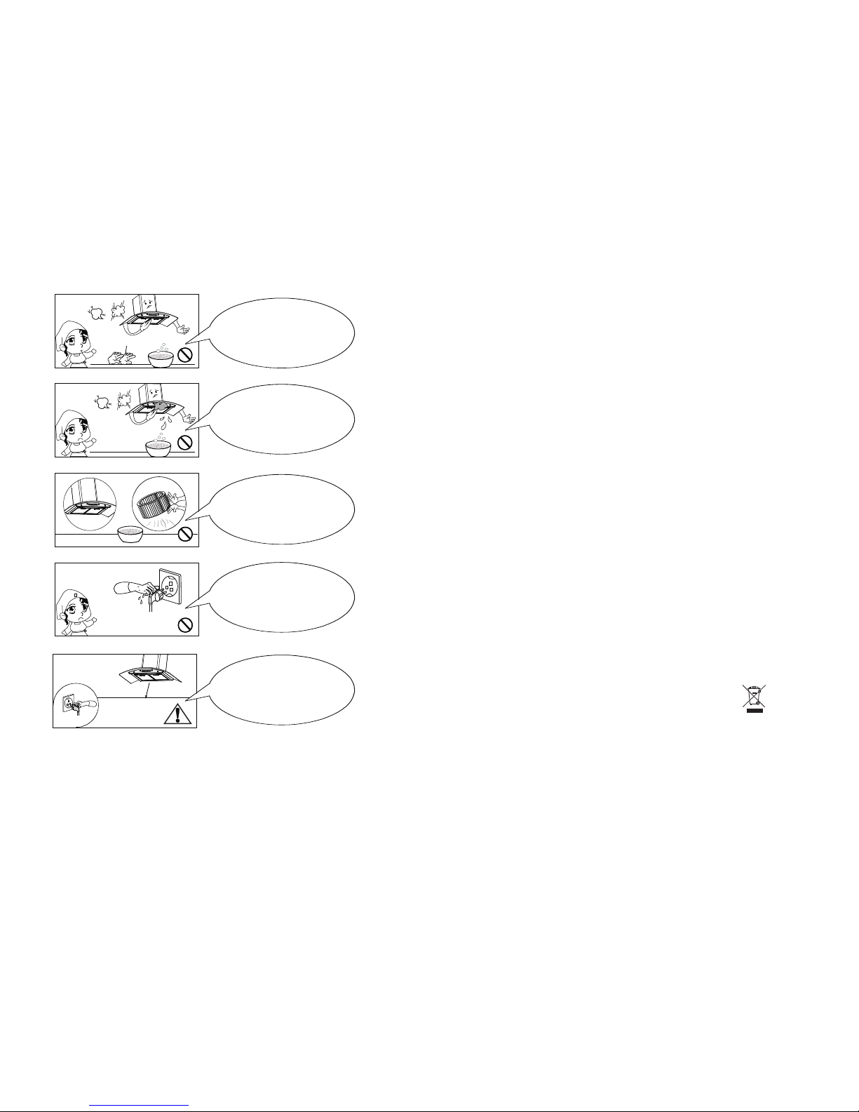
Glo ve
Dress the protective
glove before you start to
clean the hood. Remove the
components gently during
carrying out the
clearance.
Never pu ll th e plug
out of the p owe r supply by
wet hand t o avo id the
possib ili ty of electric
shock.
Never wash the
control switch with water
or other kind of liquid to avoid
the liquid might cause
electrical problem to
the hood.
To clean the motor
fan should be undertaken
by a qualified person, pay top
attention to avoid any distortion
of the fan during carrying
out the clearance.
Disconnect the
cooker hood from the
power supply if this appliance
will not be used for
a long time.
Page 4

Dear con sum er,
Thanks f or yo ur purchase of o ur co oker hood and we h ope w e can fully
satisf y all o f your needs. Pl eas e read entire in str uctions c are fully before
procee din g to obtain the be st re sults of using t he co oker hood .
MODEL NO.: Cov o 668 /90 、Covo 669/9 0GP
TOTAL PO WER: 254W
THREE SP EED M OTOR: 250 W
LED LIGH TS: 2x2W
VOLTAGE : 220 V~240V
FREQUE NCY:5 0 Hz
FILTE R: 6-layer fil ter
CONTRO L: Se nsor touch
1
TECHNICA L CH ARACTERISTICS
BODY SIZ E
10
2
IMPORTANT SAFETY IN STRUCTIONS:
Man ual
Do not connect the air
outlet to chimney flues or
combustion gas ducts.
Do not leave naked
flames under this hood
In case of any
damage to power cable,
replace the broken cable with
a new one by qualified person.
Do clean the hood
correctly in accordance
with instruction stated or it
might cause the possibility
of fire accident
To replace the bulb
should be undertaken by a
qualified electrician or a
competent person. Always
use the bulb no more
than 2W.
570 -950m m
47
5
m
m
90
0
m
m
3
0
0
mm
3
00
m
m
Page 5

29
MAIN PARTS NAME
INSTALLATIO N REQ UIREMENT
1. Do not in sta ll the cooker ho od wh ere there are ma ny doors or wind ows
in other t o avo id to effec ting the exhau st efficienc y of the hood caus ed
by air con vec tion. (Fig. 1)
CA UTI ON: L AMP UN IT MAY BE HOT !WAIT UNTIL
AN D USE T HE SA ME TY PE LI GHT B ULB !
UN IT IS C OOL .
Make sur e all c ontrol switc hes a re off,an d cooker hood is u npl ugged.
Pls foll ow be low instruct ion s:
TO REPLACE LIGHT BULB
1. Use a fla t head scre wdriver t o pop out the l amp subas sembly, th en
discon nect lamp f rom the int ernal wir es.
2. Unloo se the scre w using cro ss head scr ewdrive r.
3. Remov e the lamp co ver and tak e out of lamp b ulb.
4. Repla ce a new 2W lamp bulb , push bulb s ecurely i nto l ight s ock et.
5. Repla ce the lamp c over, fix it w ith s crew s.
6. Conne ct the lamp s ubassem bly with in ternal el ectrica l wire and pu sh the
light in to the hood l amp hole.
Warn ing! Make sure t he bu lb has cooled be fore you touch i t !
10. The sa me way to take out t he other fan.
11. After clean , ple ase assemble i t like the oppos ite w ays of loose it.
Note: Le ft mo tor fixed cove r and f an have a little d ifferen ce fr om right
side ,th ere i s a letter "R "on the ri ght s ide cover and a le tter "L"
o n th e le ft sid e cover. D on’t as s e m bl e it in w r ong side.
Blower b ox
Glass
Filter
Inner du ct co ver
Outer du ct co ver
Duct bra cke t
Exhaus t pip e
Page 6

3 8
2. Instal l the c ooker hood rig ht ab ove the hob.Th e recommende d dis tance
betwee n the h ob and the lower e dge o f the cooker hoo d is minimum
650mm an d max imum 700mm. (F ig. 2 )
3. In order t o get t he optimum per for mance, do not el ongate the exh aus t
pipe too l ong , and try to make th e ben d of exhaust pip e less and bigge st,
ensure t he co nnection is ai rpr oof.(Fig. 3)
4. After ha ngi ng the unit on the w all, ensure th e hoo d is level and ver tic al.
(Fig. 4)
650~7 00mm
Fig .1 Fig .2
5. Th e air o utlet must not b e connected to c him ney flues or com bus tion gas
ducts. T he air outlet mu st under no circ ums tances be conn ect ed to venti-
lation d uct s for room in whic h fue l-burning ap pli ances are i nst alled.
Fig .3
4. Clean t he mo tor fan and othe r ins ide parts once h alf year or acco rdi ng
to use by QU ALI FIED PERSON.
5. DO NOT cl eaning motor w ith w ater or oth er li quid.
1. Take out the fil ter s.
2. Loose t he wi re insert
and powe r sup ply wire.
3. Loose e art h wire.
4. Loose b low er fixed
screws .
5. Take out the blo wer a ssembly.
Motor fi x cover
Fan
Charco al filter
Fan fixe d screws
Blower a ssembly
Wire inse t
Power su pply
wire
Earth wi re
Blower f ixed scre ws
CLEAN THE BLOWER AS SEM BLY
6. Take out the cha rco al filter like a rro whead ’s direct ion( if you have
instal led c harcoal filt er) .
LE VEL
VE RTIC AL
Fig .4
LE AN
LE AN
8. Use hex ang ular screwdr ive r to loose the blo wer f ix screws.
9. Take out the fan .
7. Take out the mot or fi x cover like arr owh ead’s direacti on.
3. Clean t he al uminium filt er on ce a week or accor ding to use stat us.
Press th e buc kle of the alumi niu m filter sligh tly, take of f the aluminiu m
filter w ash t hem by Dishwas hel o r you can put it int o war m soapy
water us ing m ild detergent, wipe the a lum inium filter w ith s oft brush.
Replac e the f ilter after it i s dry.
Page 7

4
7
INSTALLATIO N PRO CEDURES
SA FETY WARN ING
HO OD MAY HAV E VERY S HAR P ED GES ;PL EAS E WEA R
PR OTECTIVE GLOVES I F IT IS N ECE SSA RY TO REM OVE ANY
PART S FOR I NSTALLING, CL EAN ING O R SER VIC ING.
Step 1:
Fix the po sit ion of the cooke r hoo d
in accor dan ce with the reco mme nd-
ed heigh t bet ween 650mm to 70 0mm
from the h ob an d the lower edge o f
the hood .
Step 2:
Accord ing t he space betwe en th e hole
A&B,dr ill 2 h oles in level on t he wa ll
with 8mm i n dia meter and 60-7 0mm
in depth . Pre ss the 2 expandi ng tu be
provid ed in to the holes. Tig hte n the 2
wood scr ews o f 5x60mm which
suppli ed to gether with th e hoo d to the
expand ing t ube.Make sur e it is f ixed
enough a nd ca nnot be move.H ang t he
cooker h ood o n the 2 wood screw s,
make sur e it is t o be level and sta ble .
FEDCBA
G
A、B、C th ree bo tto ns in ter act.
D: Wh en th e hood is OFF, pr ess and hold D for 3 s eco nds,and then p ress C
(to adju st th e minute) and E (t o adj ust the hour) re spectively, G acts like
a clock. On th e screen, left s ide i s hour and the rig ht side is minut e;W hen
the hood i s ope rating, touc h D to co ntrol workin g tim e of hood,1min ute
per one to uch ,the longest s tay O N time is 60 minut es.
E: Press E , tur ns on the light. P res s it again to turn o ff the ligh t.
F: Delay f orm ation: when th e hoo d is operating p res s F, the ho od will not
be OFF at on ce, i t will remain fo r one m inute before i t is OFF.
OPERATING INSTRUCTIO N
MAINT ENA NCE
CA UTI ON: N EVE R PUT YOUR H AND I NTO THE ARE A HOUS ING
TH E FAN WHILE THE FAN IS O PER ATIN G.
FO R THE O PTI MAL LEVEL OF OPE RATI ON, C LEA N THE R ANG E
HO OD SU RFACE, FAN, AND ALU MIN IUM FILT ER RE GUL ARLY.
1. Use onl y mil d soap or deterg ent solut ion s to clean the coo ker h ood
surfac e. Dr y surfaces usi ng so ft cloth.
2. Using a s tai nless steel cl ean er to bring the gl ow ba ck into a sta inl ess
steel fi nis h.
10m m
650 -700m m
Wood Sc rew
5x6 0
Exp andin g Tube
Hoo k
243m m
362m m
B
A
A: Touch A , the fan runs at t he lo w speed. Press i t again, the fan t urn s off.
B: Touch B, the fan r uns a t the mid speed. P res s it again, the fa n turns off .
C: Touch C, the fan r uns a t the high speed . Pre ss it again, the f an turns off
Page 8

5
6
Step 5:
Matchi ng th e bracket to the h ole s
of the inn er du ct cover and fix i t
well wit h M4 sc rews.
Step 6:
Insert t he in ner duct cover i nto t he
outer du ct co ver.
Please k ind ly note that the i nne r
duct cov er mu st fix to the oute r
duct cov er’s or ientation sl ot.
Step 7:
Put the ou ter d uct cover to the u nit
body, and u se two M4x10 scr ews
to fix the o ute r duct cover to th e
unit bod y.
Step 8:
1. Draw th e inn er duct cover up t o
the suit abl e high, mark on th e wal l
two keyh ole o f the outer duct c ove r
bracke t wit h a pen .
2. Put dow n the i nner duct cove r
gently, d rill the keyho les i n 60-70
mm depth o n the h orizontal le vel
using 8m m dri ll.
3. Press t he ex panding tube p rov ided
into the h ole s.
4. Match ing t he inner duct co ver w ith
the hole s, ti ghten the inne r duc t
cover wi th tw o 5x60 wood scre w
provid ed
Step 9:
Extend t he ai r outlet of the ex hau st
pipe out -of -door. Try to make t he
bend of th e exh aust pipe is mor e
than 120° .
Step 10:
Instal l gre ase filter. Mat ch the fix
pin to the f ix ho le and button th e
filter g ent ly as the direct ion o f arrow
A.
Fix p in
Fix h ole
A dire ction
Step 4:
Take o ut th e cooker hood fr om
the cart on an d put it on a horizo n-
tal work t abl e gently. Fi x the r educer
pipe int o the a ir outlet of the i nne r
duct, an d the n fix the exhaus t pip e
into the t op of r educer,make sure i t is
connec ted t o the reducer ti ght ly.
Exh aust pi pe
Air o utlet
Bra cket
Inn er duct
cov er
M4 Scr ew
Inn er duct c over
Out er duct c over
K
K
Ori entat ion Slo t
Inn er duct c over
Out er duct c over
fix s crews
5x6 0
Wood Sc rew
Exp andin g Tube
5x6 0
Wood Sc rew
Exp andin g Tube
 Loading...