

Page 1
Cookers - Cuisinières
Instruction for the use - Mode d’emploi
COOK
130 cm
MASTERline
Page 2

2
Identification label
Plaquette des caractéristiques
136 EX 634
136 EX 636
136 EX 838
Models - Modéles
Mode d’emploi - Conseils pour l’installation
Français Page 55
Instruction for the use - Installation advice
English Page 3
Page 3

3
Dear Customer,
Thank you for having purchased and given your preference to our
product.
The safety precautions and recommendations reported below are for
your own safety and that of others. They will also provide a means by
which to make full use of the features offered by your appliance.
Please preserve this booklet carefully. It may be useful in future,
either to yourself or to others in the event that doubts should arise
relating to its operation.
This appliance must be used only for the task it has explicitly been
designed for, that is for cooking foodstuffs. Any other form of usage
is to be considered as inappropriate and therefore dangerous.
The manufacturer declines all responsibility in the event of
damage caused by improper, incorrect or illogical use of the
appliance.
Instruction for the use
English
GB
DECLARATION OF CECONFORMITY
This cooking hob has been designed, constructed, and marketed in compliance with:
- Safety requirements of the "Gas" Directive 90/396/EEC;
- Safety requirements of EEC Directive “Low voltage” 73/23;
- Safety requirements of EEC Directive “EMC” 89/336;
- Requirements of EEC Directive 93/68.
Page 4

4
TIPS FOR THE USER
•
During and after use of the cooker,
certain parts will become very hot.
Do not touch hot parts.
•
Keep children away from the cooking hob when it is in use.
•
After use, ensure that the knobs are
in position ● (off), and close the
main gas delivery valve or the gas
cylinder valve.
•
In case of difficulty in the gas taps
operation, call Service.
Risk of fire!
•
Do not leave inflammable material
on the cooktop, on the ovens or on
the drawer.
•
Make sure that the electrical cables
of other appliances installed nearby
cannot come into contact with the
cooktop.
IMPORTANT INSTRUCTIONS AND
ADVICE FOR THE USE OF ELECTRICAL
APPLIANCES
The use of any electrical appliance
requires the compliance with some
basic rules, namely:
– do not touch the appliance with wet
or damp hands (or feet)
– do not use the appliance bare feet
– do not allow the appliance to be
operated by children or disabled
without overseeing.
The manufacturer cannot be deemed
responsible for damages caused by
wrong or incorrect use.
IMPORTANT:
This appliance is designed and manufactured solely for the cooking of domestic
(household) food and is not suitable for any non domestic application and therefore
should not be used in a commercial environment.
The appliance guarantee will be void if the appliance is used within a non domestic
environment i.e. a semi commercial, commercial or communal environment.
Page 5

5
USEFUL HINTS
After removing the appliance from its
packing, make sure of its integrity.
In case of doubt, please apply to your
supplier or to a qualified engineer.
The packing materials (plastic bags,
polyfoam, nails, metal strips etc.) must
be moved away from the reach of the
children as potential sources of danger.
– Do not attempt to alter the technical
features of the appliance as this may
result very dangerous.
– Do not carry out any operation of
cleaning or maintenance without prior
disconnection of the appliance from
the electric supply.
– Do not line the oven walls with alu-
minium foil. Do not place baking trays
or the drip tray on the base of the
oven chamber.
– If you should decide not to use this
appliance any longer (or decide to
substitute an older model), before disposing of it, it is recommended that it
be made inoperative in an appropriate
manner in accordance to health and
environmental protection regulations,
ensuring in particular that all potentially hazardous parts be made harmless, especially in relation to children
who could play with old appliances.
– Appliances produce heat and humidi-
ty in the environment in which they are
installed.
Ensure that the cooking area is well
ventilated by opening the natural
ventilation grilles or by installing an
extractor hood connected to an outlet duct.
– If the appliance is used for a pro-
longed time it may be necessary to
provide further ventilation by opening
a window or by increasing the suction
power of the extractor hood (if fitted).
– Read the instructions carefully before
installing and using the appliance.
CAUTION: this apparatus must only
be installed in a permanently ventilated room in compliance with the applicable regulations.
FIRST USE THE OVEN
It is advised to follow these instructions:
• Furnish the interior of the oven by
placing the wire racks as described at
chapter “
CLEANING AND MAINTE-
NANCE
”.
• Insert shelves and tray.
• Turn on the oven, and operate at the
maximum temperature in order to
eliminate any traces of grease on the
heating elements (see oven operating
instructions for the specific model).
• Clean the interior of the oven with
cloth soaked in water and detergent
(neutral) then dry carefully.
Page 6
6
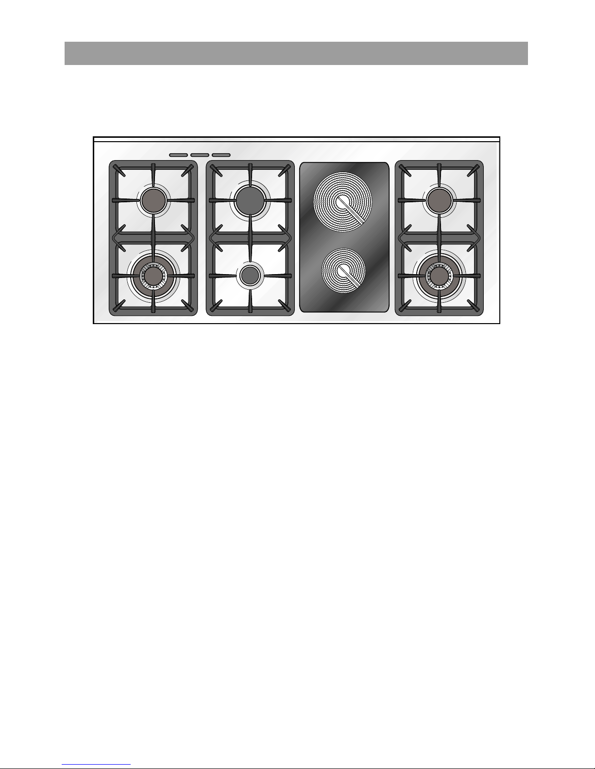
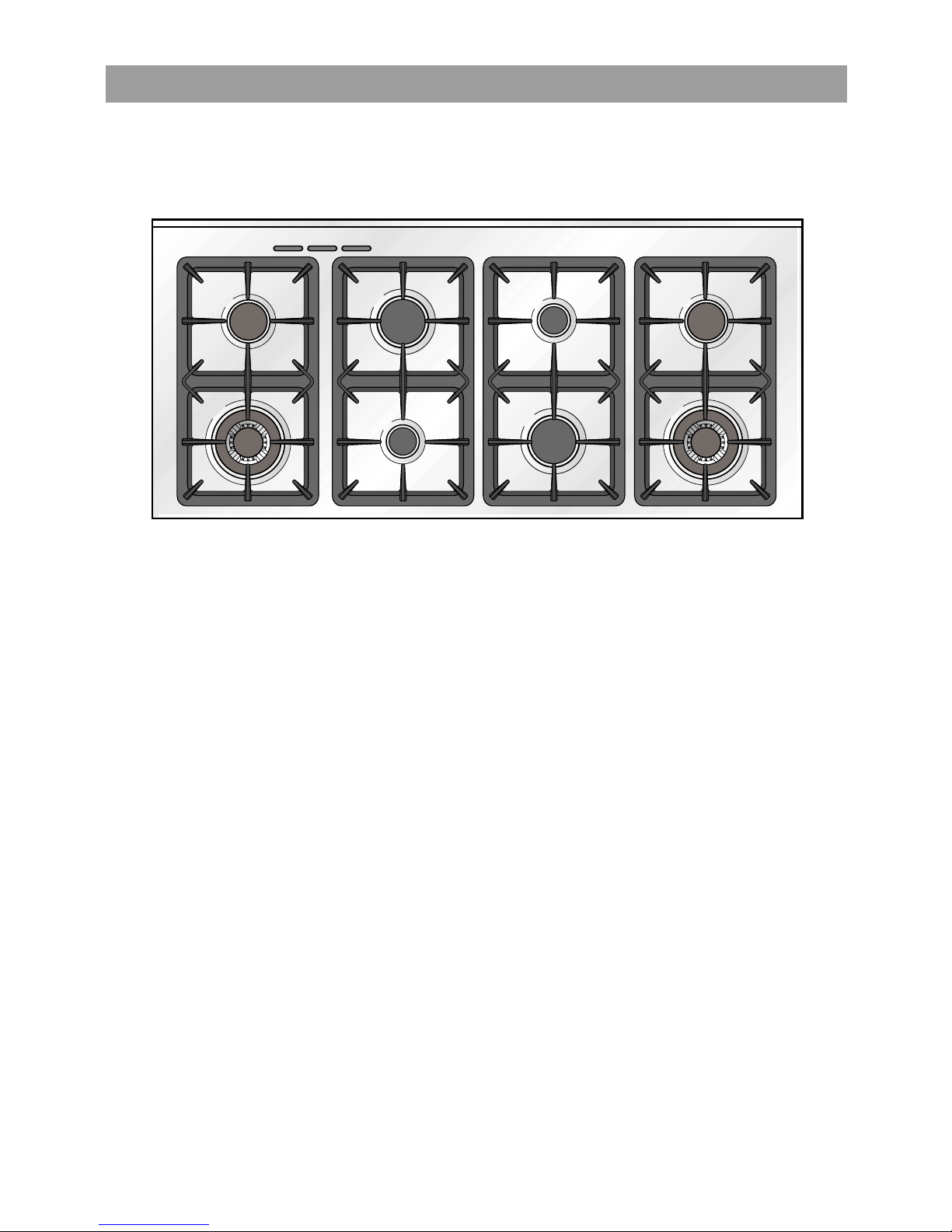
11 COOKING HOB
Fig. 1.1a
2
3
4
4
1
2
5
6
TECHNICAL FEATURES - Cooking hob
1. Auxiliary burner (A) 1,00 kW
2. Semi-rapid burner (SR) 1,75 kW
3. Rapid burner (R) 3,00 kW
4. Triple-ring burner (TC) 3,50 kW
5
. Hi-light cooking zone
Ø 180 1800 W
6.
Hi-light cooking zone
Ø 145 1200 W
136 EX 634
Cooker: Cat: II 2H3+
Note:
The electric ignition is incorporated in the knobs.
The appliance has a safety valve system fitted, the flow of gas will be stopped if and
when the flame should accidentally go out.
Attention: Do not use the ceramic zones if the glass surface is broken or cracked in any
way. Please disconnect the appliance from the mains and contact the after-sales service.
Page 7
7
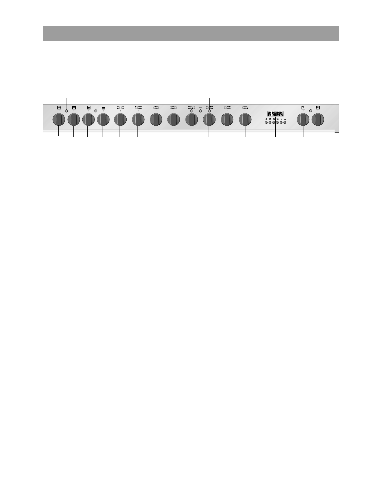
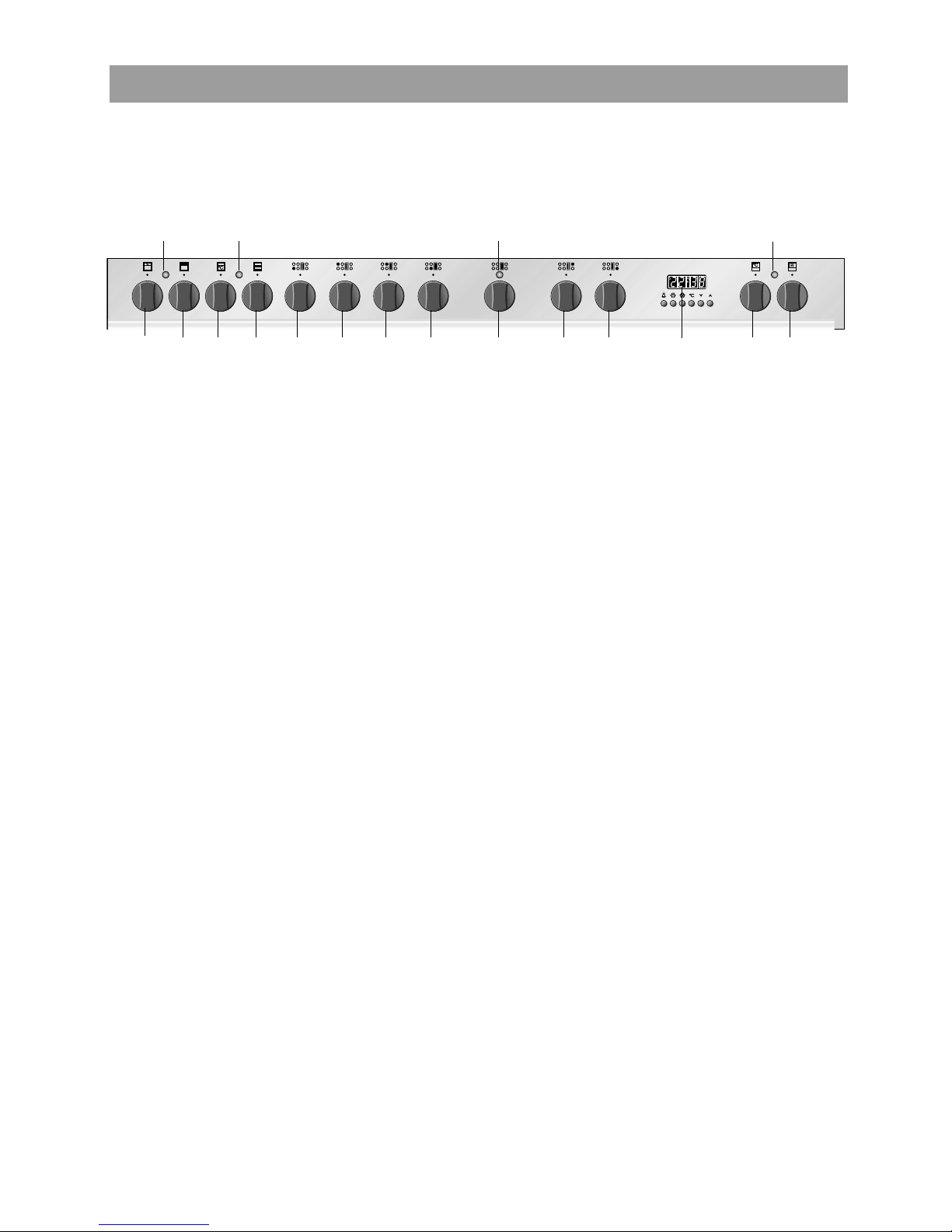
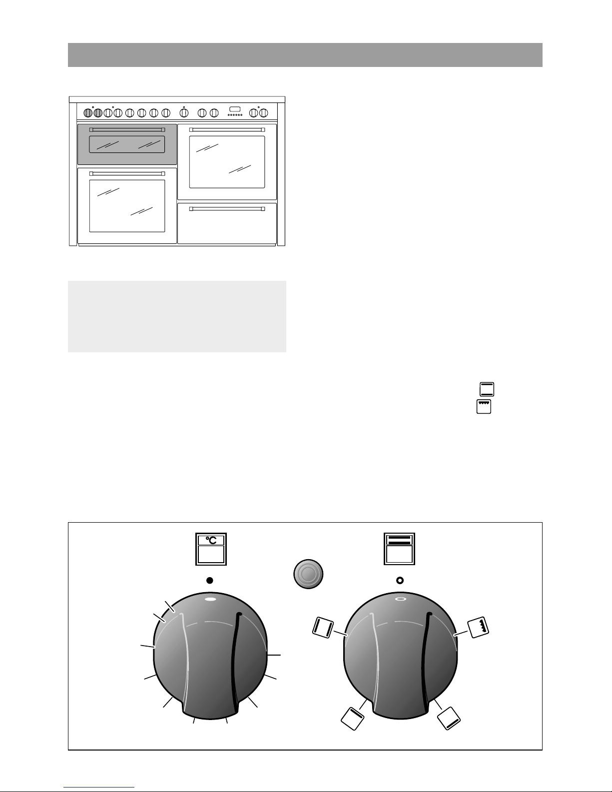
CONTROL PANEL
136 EX 634
Fig. 1.1b
CONTROL PANEL - Controls description
1.Conventional oven thermostat knob (top left oven)
2. Conventional oven switch knob (top left oven)
3.Conventional oven thermostat knob (bottom left oven)
4. Conventional oven switch knob (bottom left oven)
5. Front left triple-ring burner control knob (4)
6. Rear left semi-rapid burner control knob (2)
7. Rear central rapid burner control knob (3)
8.Front central auxiliary burner control knob (1)
9. Front central hi-light cooking zone control knob (6)
10. Rear central hi-light cooking zone control knob (5)
11.Rear right semi-rapid burner control knob (2)
12.Front right triple-ring burner control knob (4)
13.Electronic programmer
(
right
oven only)
14.Multifunction oven thermostat knob(right
oven)
15.
Multifunction oven switch knob(right
oven)
16.Indicator light (right
oven
)
17. Rear cooking zone residual heat indicator
18. Cooking zones control lamp
19. Front cooking zone residual heat indicator
20.Indicator light (bottom left oven)
21.Indicator light (top left oven)
A
U
T
O
1234 5 7689101112 1415
13
1619 18 1720
21
Page 8
8
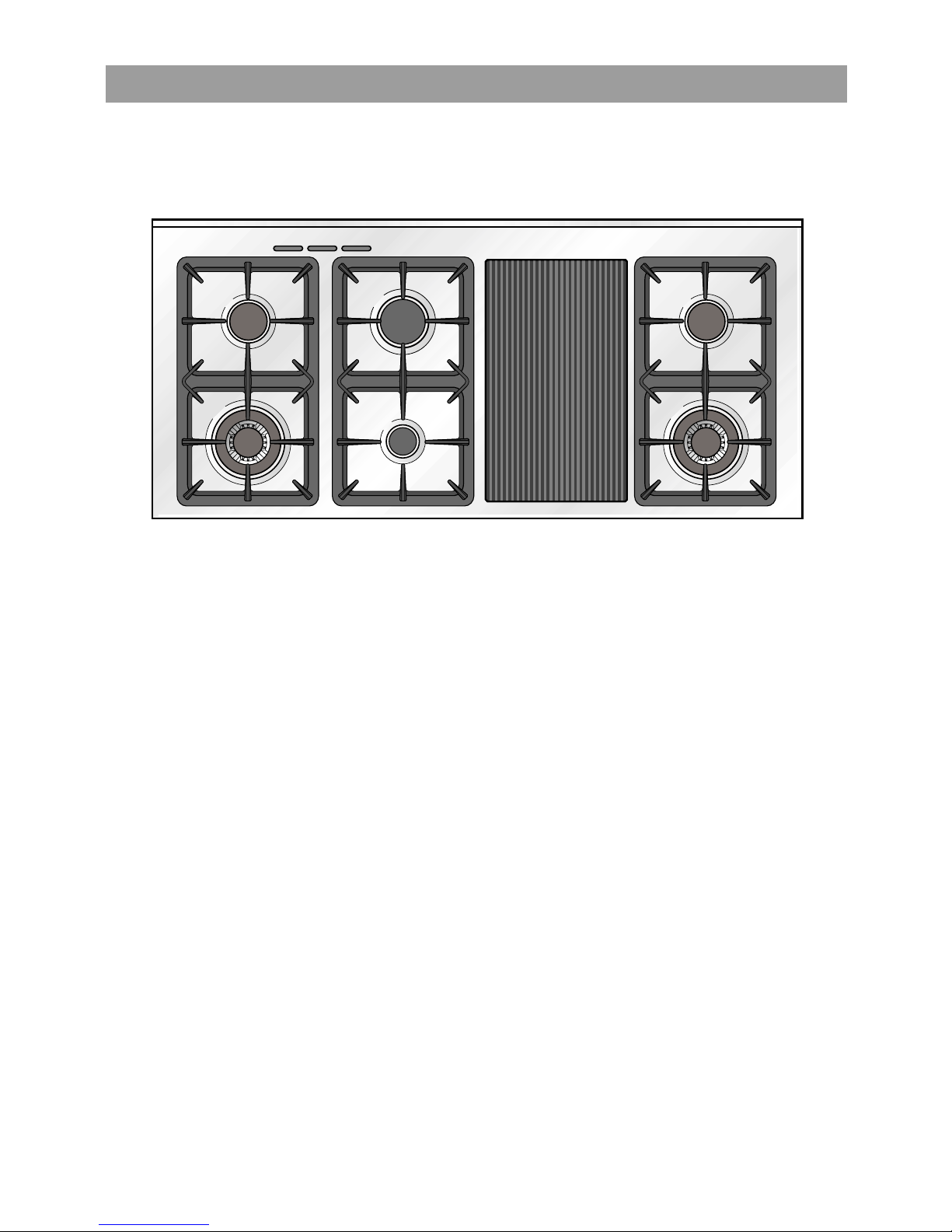
COOKING HOB
Fig. 1.2a
2
3
4
4
1
2
5
TECHNICAL FEATURES - Cooking hob
1. Auxiliary burner (A) 1,00 kW
2. Semi-rapid burner (SR) 1,75 kW
3. Rapid burner (R) 3,00 kW
4. Triple-ring burner (TC) 3,50 kW
5. Ceramic griddle 1300 W
136 EX 636
Note:
The electric ignition is incorporated in the knobs.
The appliance has a safety valve system fitted, the flow of gas will be stopped if and
when the flame should accidentally go out.
Attention: Do not use the ceramic griddle if the glass surface is broken or cracked in any
way. Please disconnect the hob from the mains and contact the after-sales service.
Cooker: Cat: II 2H3+
Page 9
9
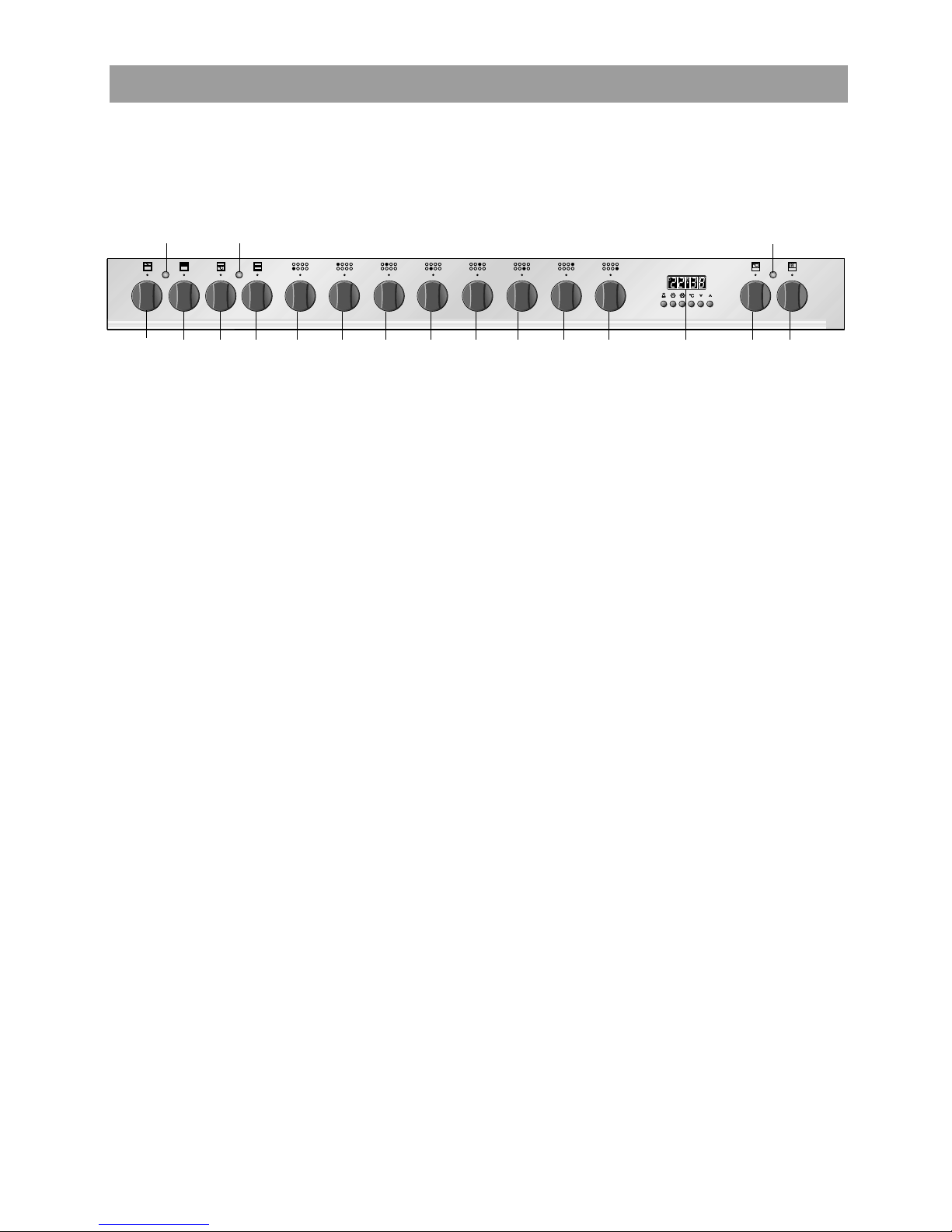
CONTROL PANEL
136 EX 636
CONTROL PANEL - Controls description
1.Conventional oven thermostat knob (top left oven)
2. Conventional oven switch knob (top left oven)
3.Conventional oven thermostat knob (bottom left oven)
4. Conventional oven switch knob (bottom left oven)
5. Front left triple-ring burner control knob (4)
6. Rear left semi-rapid burner control knob (2)
7. Rear central rapid burner control knob (3)
8.Front central auxiliary burner control knob (1)
9. Ceramic griddle control knob (5)
10.Rear right semi-rapid burner control knob (2)
11.Front right triple-ring burner control knob (4)
12.Electronic programmer
(
right
oven only)
13.Multifunction oven thermostat knob(right
oven)
14.
Multifunction oven switch knob(right
oven)
15.Indicator light (right
oven
)
16. Ceramic griddle control lamp
17.Indicator light (bottom left oven)
18.Indicator light (top left oven)
Fig. 1.2b
A
U
T
O
12345 76891011 1314
12
151617
18
Page 10
10
COOKING HOB
Fig. 1.3a
2
3
3
4
4
1
1
2
TECHNICAL FEATURES - Cooking hob
1. Auxiliary burner (A) 1,00 kW
2. Semi-rapid burner (SR) 1,75 kW
3. Rapid burner (R) 3,00 kW
4. Triple-ring burner (TC) 3,50 kW
136 EX 838
Note:
The electric ignition is incorporated in the knobs.
The appliance has a safety valve system fitted, the flow of gas will be stopped if and
when the flame should accidentally go out.
Cooker: Cat: II 2H3+
Page 11
11
CONTROL PANEL
136 EX 838
CONTROL PANEL - Controls description
1.Conventional oven thermostat knob (top left oven)
2. Conventional oven switch knob (top left oven)
3.Conventional oven thermostat knob (bottom left oven)
4. Conventional oven switch knob (bottom left oven)
5. Front left triple-ring burner control knob (4)
6. Rear left semi-rapid burner control knob (2)
7. Rear left central rapid burner control knob (3)
8.Front left central auxiliary burner control knob (1)
9. Rear right central auxiliary burner control knob (1)
10. Front right central rapid burner control knob (3)
11.Rear right semi-rapid burner control knob (2)
12.Front right triple-ring burner control knob (4)
13.Electronic programmer
(
right
oven only)
14.Multifunction oven thermostat knob(right
oven)
15.
Multifunction oven switch knob(right
oven)
16.Indicator light (right
oven
)
17.Indicator light (bottom left oven)
18.Indicator light (top left oven)
Fig. 1.3b
A
U
T
O
12345 7689101112 1415
13
1617
18
Page 12
12
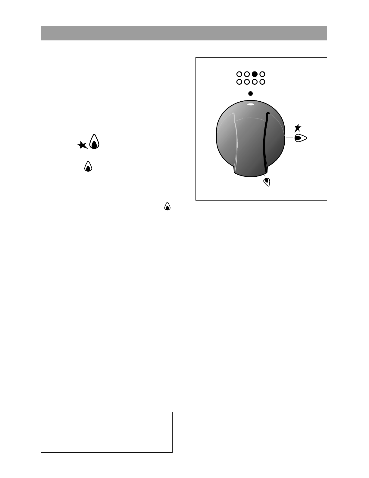
22 USE OF COOKING HOB
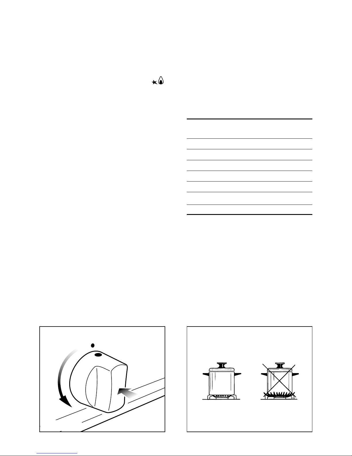
Fig. 2.1
GAS BURNERS
Each burner is controlled by a gas tap
assuring the opening and the closing of
the gas supply (Fig. 2.1).
Make the lever of the knob match with
the indicator on the control panel to
obtain:
– symbol
● = off
– symbol = full on
(nominal rate)
– symbol = reduced rate
- The electric ignition is incorporated in
the knobs (★ symbol beside flame
- max. heat/max. gas flow fig. 2.1).
- The maximum setting permits rapid
boiling of liquids, whereas the minimum setting allows slower warming of
food or maintaining simmering conditions of liquids.
- Other intermediate operating can be
achieved by positioning the control
knob indicator between the maximum
and minimum setting, but not between
the maximum and off positions.
N.B. When the cooker is not being used,
set the gas knobs to their closed positions and also close the cock valve on
the gas bottle or the main gas supply
line.
Caution!
the cooking hob becomes very hot
during operation.
Keep children well out of reach.
Page 13
13
Fig. 2.3
Fig. 2.2
LIGHTING GAS BURNERS FITTED
To ignite the burner, the following
instructions are to be followed:
1) Press in the corresponding knob and
turn counter-clockwise (fig. 2.2 to the
full flame position marked by the
symbol (fig. 2.1) and hold the knob in
until the flame has been lit.
In the case of a mains failure light the
burner with a match or lighted taper.
2) Wait for about ten seconds after the
gas burner has been lit before letting
go of the knob (valve activation
delay).
3) Adjust the gas valve to the desired
position.
If the burner flame should go out for
some reason, the safety valve will automatically stop the gas flow.
To re-light the burner, return the knob to
the closed
● position, wait for at least
1 minute and then repeat the lighting
procedure.
If your local gas supply makes it difficult
to light the burner with the knob set to
maximum, set the knob to minimum and
repeat the operation.
CHOICE OF THE BURNER
On the control panel, near every knob,
there is a diagram that indicates which
burner is controlled by that knob.
The suitable burner must be chosen
according to the diameter and the
capacity used.
As an indication, the burners and the
pots must be used in the following way:
It is important that the diameter of the
pot be suitable to the potentiality of the
burner so as not to compromise the high
output of the burners and therefore
energy waste.
A small pot on a large burner does not
give you a boiling point in a shorten
amount of time since the capacity of
heat absorption of a liquid mass
depends on the volume and the surface
of the pot.
DIAMETERS OF PANS WHICH MAY BE USED
ON THE HOBS
BURNERS MINIMUM MAX.
Auxiliary 12 cm 14 cm
Semirapid 16 cm 24 cm
Rapid 24 cm 26 cm
Triple-ring 26 cm 28 cm
Wok max 36 cm
do not use pans with concave or convex bases
Page 14
14
Fig. 2.4b
Fig. 2.4a
WRONG
CORRECT
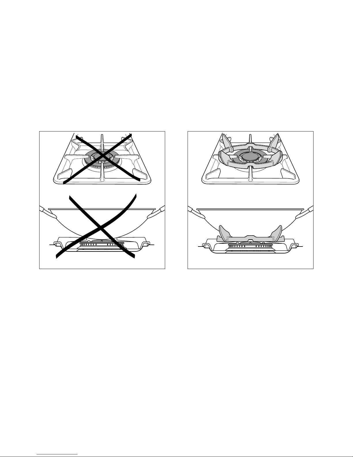
SPECIAL GRID FOR WOKS (fig. 2.4a - 2.4b)
The special grid for woks rests on the grid of the triple ring burner.
Warning:
– Using woks without this special grid could seriously damage the burner.
– Do not use this grid with flat bottomed pans (fig. 2.4a - 2.4b).
IMPORTANT:
The special grille for wok pans (fig. 2.4b) MUST BE PLACED ONLY over the pan-rest for
the triple-ring burner.
Page 15
15
Fig. 2.6
1
2
3
4
5
6
7
8
9
10
11
12
Fig. 2.5
USE OF VITROCERAMIC HOB
IMPORTANT NOTE:
The heating elements incorporate a
thermolimiter that switches ON/OFF the
element in all settings to protect any
overheating of the ceramic glass.
The use of incorrect pans and/or wrong
pan positioning will cause the temperature limiter to operate more frequently,
resulting in a reduction of cooking performance.
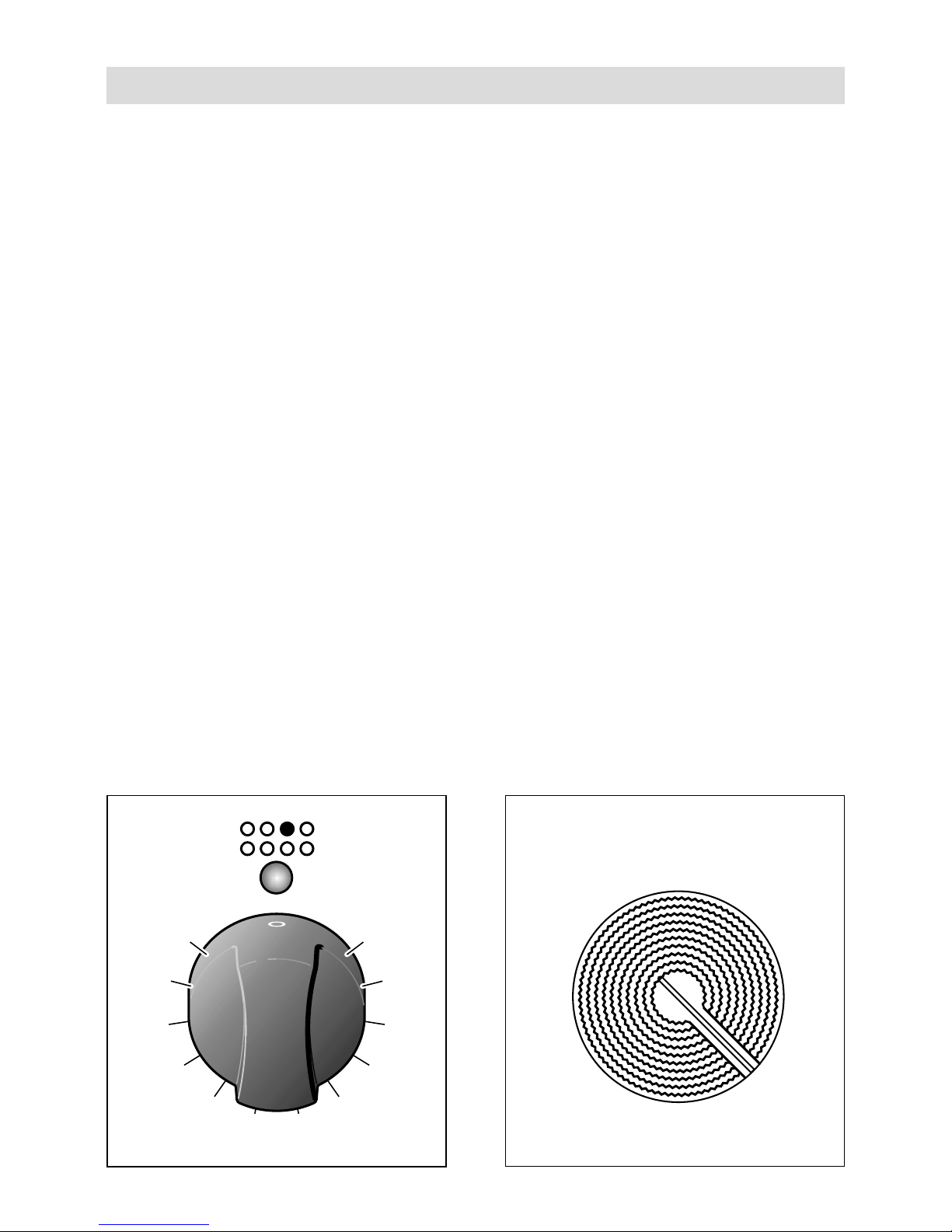
“HI-LIGHT” RADIANT ZONES
The heating element is formed of a coil
of resistant material which reaches the
working temperature quickly.
Operation of the cooking zone is controlled by a continuous energy regulator
from 1 (minimum position) to 12 (maximum temperature).
“HI-LIGHT” RADIANT ZONE
CONTROL KNOBS
Operation of the cooking zone is controlled by a continuous energy regulator
from 1 (minimum position) to 12 (maximum temperature) fig. 2.5.
The heat intensity can be regulated continuously from “0” (off) to “12” (max).
The ceramic surface of the hob allows a
fast transmission of heat in the vertical
direction, from the heating elements
underneath the ceramic glass to the
pans set on it.
The heat does not spread in the horizontal direction, so that the glass stays
“cool” at only a few centimetres from the
cooking plate.
The 2 cooking zones are shown by dark
disks on the ceramic surface.
Check that the cooker top is clean.
Page 16
16
After a short period of use, experience will teach you which setting is the right one for
your needs.
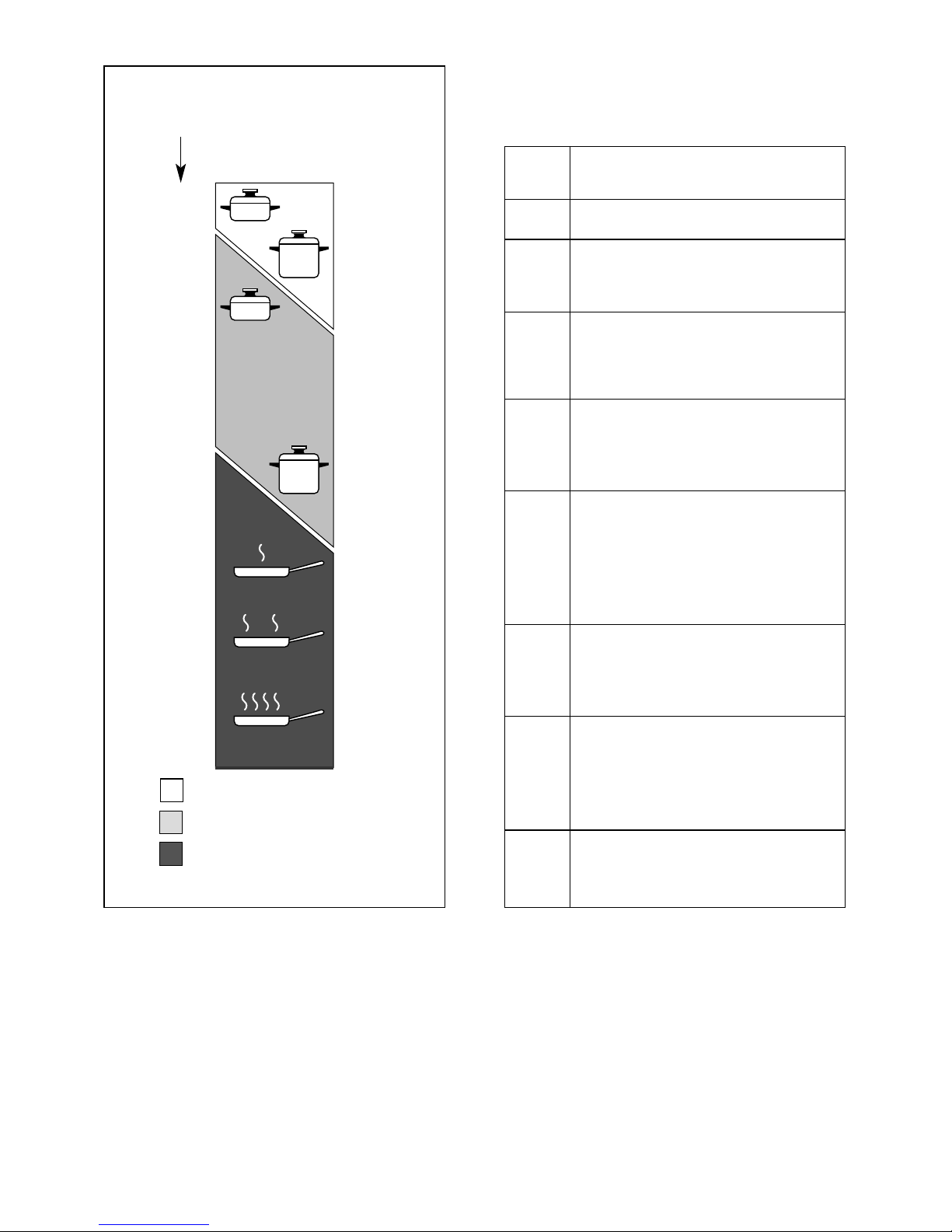
COOKING HINTS
Cooking plate
controlled 12
position switch
Fig. 2.7
1
2
3
4
5
6
7
8
9
10
11
12
Heating
Cooking
Roasting-frying
TYPE OF COOKING
Switched OFF
For melting operations
(butter, chocolate).
To maintain food hot and to
heat small quantities of liquid (sauces, eggs).
To heat bigger quantities; to
whip creams and sauces.
(vegetables, fruits, soups).
Slow boiling, i.e.: boiled
meats, spaghetti, soups,
continuations of steam cooking of roasts, stews, potatoes.
For every kind of frying, cutlets, uncovered cooking, i.e.:
risotto.
Browning of meats, roasted
potatoes, fried fish,
omelettes, and for boiling
large quantities of water.
Fast frying, grilled steaks,
etc.
0
Position
of switch
1
2
4
5
6
2
3
4
6
7
7
8
8
9
10
11
12
Page 17

17
Fig. 2.8
Caution!
the cooking hob becomes very
hot during operation.
Keep children well out of reach.
Do not scratch the cooktop with
cutting or sharp objects.
Do not use the cooktop as a work
surface.
RESIDUAL HEAT INDICATOR
The appliance also features 2 warning
lights (located in the control panel above
the Hi-light zone control knobs) which
are connected to the corresponding
plate.
When the temperature of a cooking plate
is above 60°C, the relevant warning
lights will also light up to warn of heat on
the surface of the hob.
This light also stays on after the cooking
plate has been switched off to show that
the hob surface is still hot.
This residual heat will lasts for a long
time after the cooking plate has been
switched off.
During this time you should avoid
touching the hob surface over the
cooking area.
Please pay special attention to
ensure that children are not
allowed near the hob.
The light will switch off automatically as
soon as the surface temperature of the
cooking plate falls below 60°C.
COOKING HINTS:
– To reduce the cooking time, you can
turn the control knob to the max when
you switch the plate on.
After a short time you can set the
control knob to the position required
for cooking.
– You should only use pots and pans
with flat bases (pans with the test
mark for glass-ceramic hobs are
available from specialist shops).
The diameter of the pan should match
that of the cooking plate (or be slightly
bigger) to make the most of the
energy.
– Since the cooking surface will stays
hot for a certain time after the plate
has been switched off, you can switch
it off 5 or 10 minutes before the end
of the cooking.
The residual heat of the hob will
complete the cooking.
– To save electricity, use pan lids
whenever possible.
– Never cook the food directly on the
glass ceramic cooktop.
Page 18
18
CLEANING
Before you begin cleaning make sure
that the appliance is switched off.
Remove spillages and other types of
incrustations.
Dust or food particles can be removed
with a damp cloth.
If you use a detergent, please make sure
that it is not abrasive or scouring.
Abrasive or scouring powders can damage the glass surface of the hob.
All traces of the cleaner must be
removed with a damp cloth.
Do not put articles on the hob which can
melt: i.e plastic, aluminium foil, sugar,
sugar syrup mixtures etc.
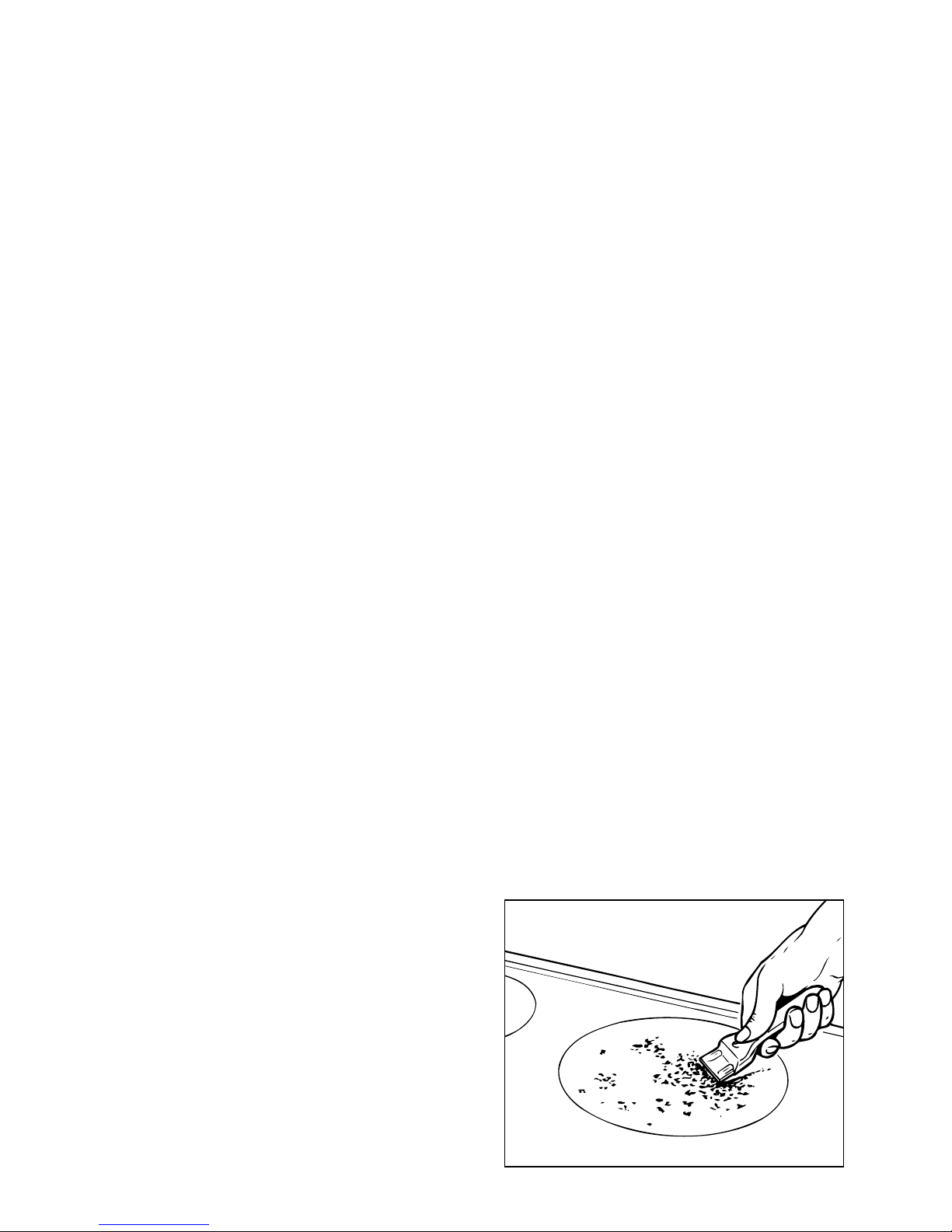
If any of these products items have melted on the ceramic surface, you should
remove it immediately (when the surface
is still hot) by using a scraper to avoid
any permanent damage to the surface of
the hob.
Avoid using a knife or other sharp utensils since these can damage the ceramic.
Do not use steel wool or an abrasive
sponge which could scratch the surface
permanently.
ATTENTION: MOST IMPORTANT!
If cleaning the glass ceramic hob
using a special scraper tool take extra
care to avoid damaging the seal at the
edges of the glass ceramic surface.
Fig. 2.9
HINTS FOR SAFE USE OF THE HOBS
– Before switching on, check which
knob controls the required hob. You
are advised to place the saucepan on
the hob before switching on and to
take it off after switching off.
– Use saucepans with an even flat bot-
tom (be careful of cast iron
saucepans). Uneven bottoms can
scratch the pyroceram surface. Check
that the bottom is clean and dry.
– Check that the saucepan handle does
not protrude from the top to avoid
knocking it over. This precaution also
makes it more difficult for children to
reach the saucepan.
– Do not use the top if the surface is
broken or damaged.
– Do not bend over the hobs when they
are on.
– Do not leave aluminium foil, grease-
proof paper etc. or plastic on the hob
when it is hot.
– Remember that the hobs stay hot for
quite a long time (approx. 30 min.)
after they have been switched off.
– Scrupulously follow the cleaning
instructions.
– Do not drop heavy or sharp objects on
the glass ceramic cooktop.
– If you note a crack in the cooktop,
switch the appliance off immediately and call the After-Sales Service.
– Never cook the food directly on the
glass ceramic cooktop, but in special
pans or containers.
Page 19
19
1
2
3
4
5
6
7
8
9
10
11
12
Fig. 2.10
CERAMIC GRIDDLE
Caution!
The griddle becomes very hot during use and remains very hot even
after it is switched off.
Keep children well out of reach.
USING THE CERAMIC GRIDDLE FOR
THE FIRST TIME
– Remove the adhesive film which pro-
tects some parts.
– Remove any residual glue carefully,
without using abrasive substances, to
avoid scratching the surfaces.
– Clean the cooking surface carefully.
– Switch the griddle on by turning the
power setting knob to the maximum
position (11-12) for about 15 minutes
to remove residual working greases.
The griddle reaches the working temperature very quickly and can grill any food,
without fat and oil, directly on the radiant
zone's glass-ceramic surface.
Operation of the radiant zone is controlled by a continuous
12-position power regulator.
The signal lamp lights up when the griddle is ON.
USE OF THE CERAMIC GRIDDLE
– Before cooking make sure that the
radiant zone is clean.
– Switch the griddle on by turning the
knob to position 12.
– Preheat until the cooking surface
becomes red.
– Then turn the knob to the position
required. The numbers from 1 to 12
indicate the working positions with
temperature increasing as the number
increases.
– Place the food on the radiant zone
and check the cooking by eye.
– Turn off the griddle by turning the
knob to position “0”.
– As the radiant zone remains hot for
some time after the hob is switched
off, turn the zone off a few minutes
before the end of cooking.
The residual heat will complete the
cooking.
– Do not use the griddle for more
than 30 minutes.
Page 20

20
TIPS FOR GRILLING:
– Preheat the radiant zone sufficiently to
obtain quick and uniform cooking.
– Do not pour water on the cooking sur-
face when it is switched on or still hot.
– If cooking very fatty foods, leave the
griddle switched on for a few minutes
after cooking is finished, to burn off
the fatty residues.
ADVICE FOR THE SAFE USE OF
CERAMIC GRIDDLE
– Do not lean on the cooking zones
when they are switched on.
– Do not put aluminium foil or plastic
objects on the cooking zones when
they are hot.
– Do not leave objects of any type on
the surfaces made of ceramic, glass
or similar fragile material.
– Remember that the cooking zones
remain hot for some time after they
are switched off (about 30 min.).
– Follow the cleaning instructions care-
fully.
– If you note a crack in the cooktop,
switch the appliance off immediately
and call the After-Sales Service.
Do not scratch the cooktop with
cutting or sharp objects.
Do not use the cooktop as a work
surface.
CAUTION: Never use abrasive substances or no-neutral detergent
which could irreversibly damages.
CLEANING THE CERAMIC GRIDDLE
Make sure that the cooktop is switched
off before cleaning it.
– Remove any encrustation.
– Remove dust with a damp cloth.
– Detergents can be used, but they
must not be abrasive or corrosive.
– Any remaining detergent must be
completely removed with a damp
cloth.
– Do not put any objects on the cooktop
which can melt with heat, such as
plastic objects, aluminium foil, sugar
or sugar products.
– If any object melts on the cooktop,
remove it immediately (while the cooktop is still hot) using a special scraper,
to prevent any irreversible damage to
the glass ceramic surface.
– Do not use knives or sharp objects
which could damage the cooktop surface.
– Do not use abrasive sponges or pads
which could irreversibly damage the
glass ceramic surface.
Page 21
21
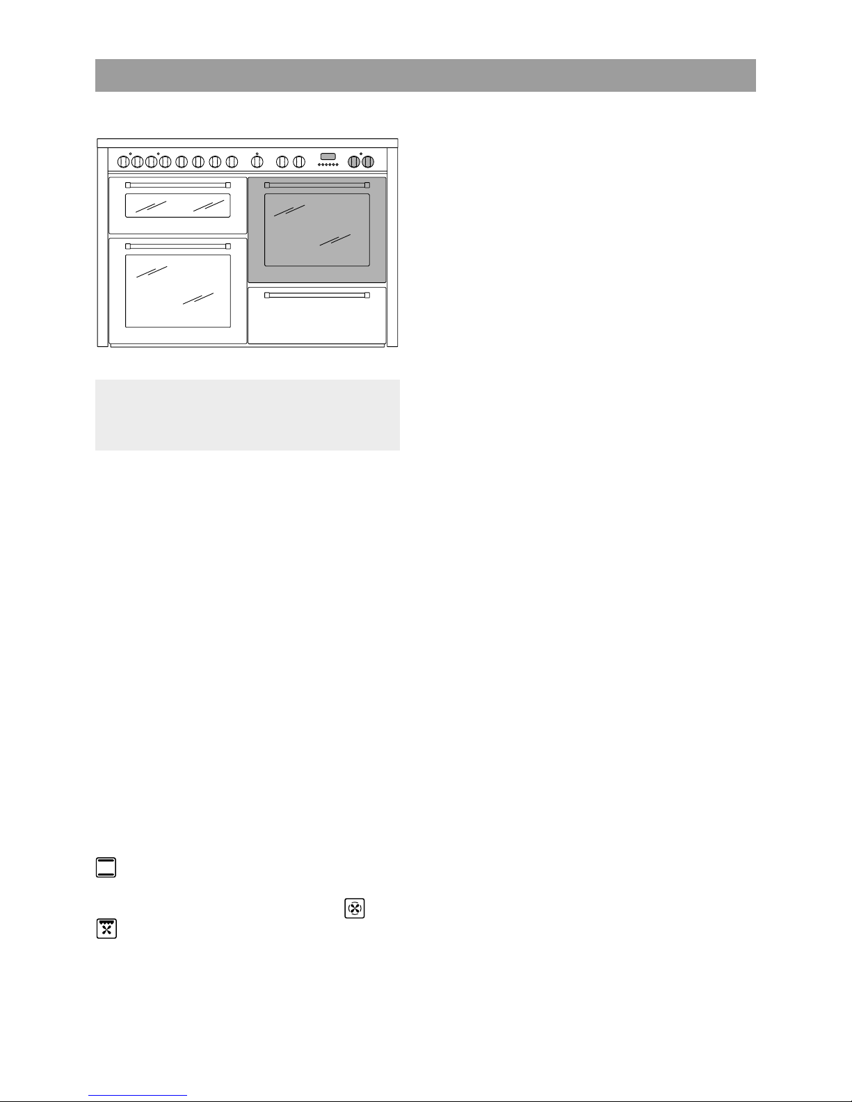
33 MULTIFUNCTION ELECTRIC OVEN (Right oven)
Attention: the oven door becomes
very hot during operation.
Keep children away
GENERAL FEATURES
As its name indicates, this is an oven
that presents particular features from an
operational point of view.
In fact, it is possible to insert 7 different
programs to satisfy every cooking need.
The 7 positions, thermostatically controlled, are obtained by 4 heating elements which are:
– Bottom element 1300 W
– Top element 1000 W
– Grill element 2000 W
– Circular element 2200 W
NOTE:
Upon first use, it is advisable to operate
the oven for 30 minutes in the position
and for another 15 minutes at the
maximum temperature (thermostat knob
on position 250) in the positions and
, to eliminate possible traces
of grease on the heating elements.
Clean the oven and accessories with
warm water and washing-up liquid
.
OPERATING PRINCIPLES
Heating and cooking in the MULTIFUNCTION oven are obtained in the following ways:
a. by normal convection
The heat is produced by the upper and
lower heating elements.
b. by forced convection
A fan sucks in the air contained in the
oven muffle, which sends it through
the circular heating element and then
sends it back through the muffle.
Before the hot air is sucked back
again by the fan to repeat the
described cycle, it envelops the food in
the oven, provoking a complete and
rapid cooking.
It is possible to cook several dishes
simultaneously.
c. by semi-forced convection
The heat produced by the upper and
lower heating elements is distributed
throughout the oven by the fan.
d. by radiation
The heat is irradiated by the infra red
grill element.
e. by radiation and ventilation
The irradiated heat from the infra red
grill element is distributed throughout
the oven by the fan.
f. by ventilation
The food is defrosted by using the fan
only function without heat.
WARNING:
The door is hot, use the handle.
Page 22
22
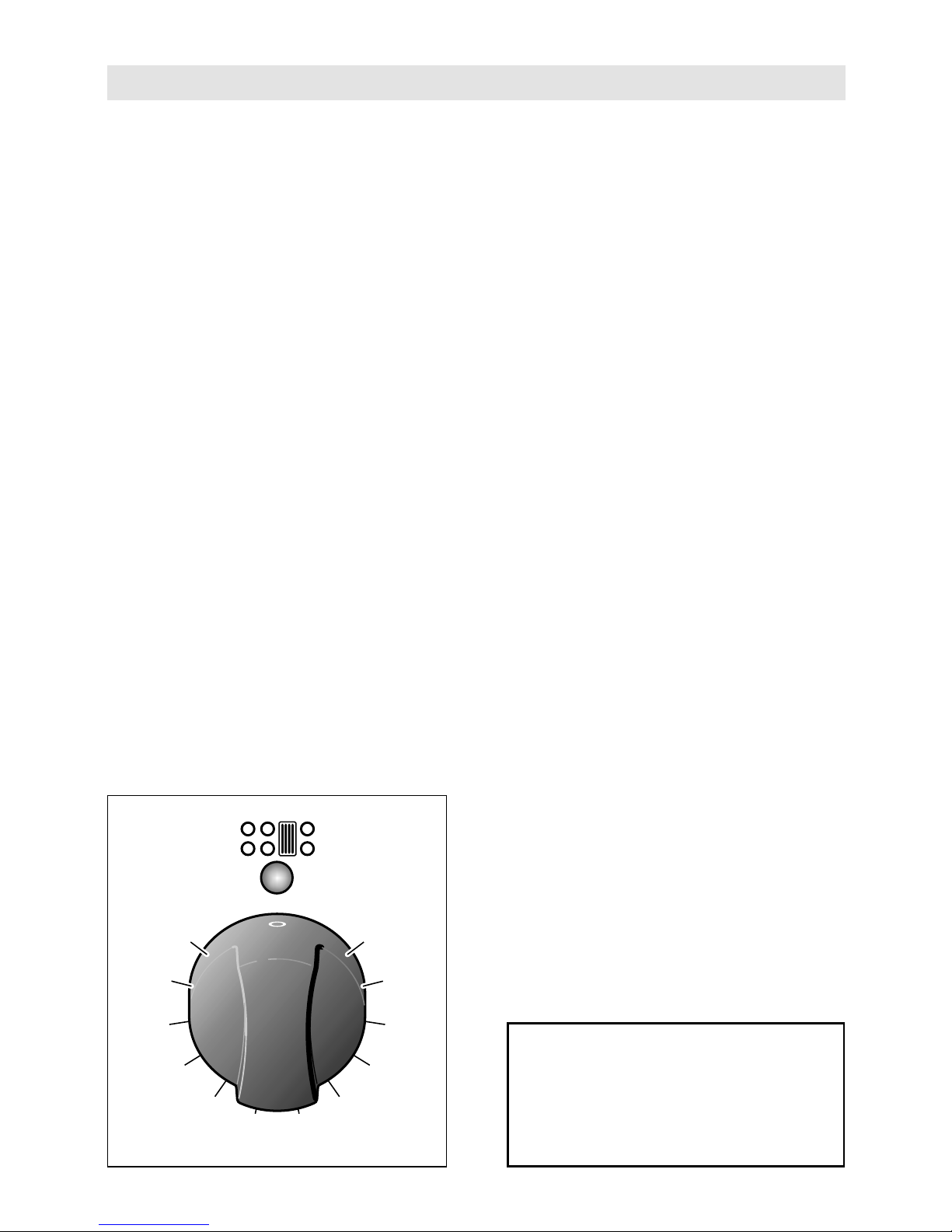
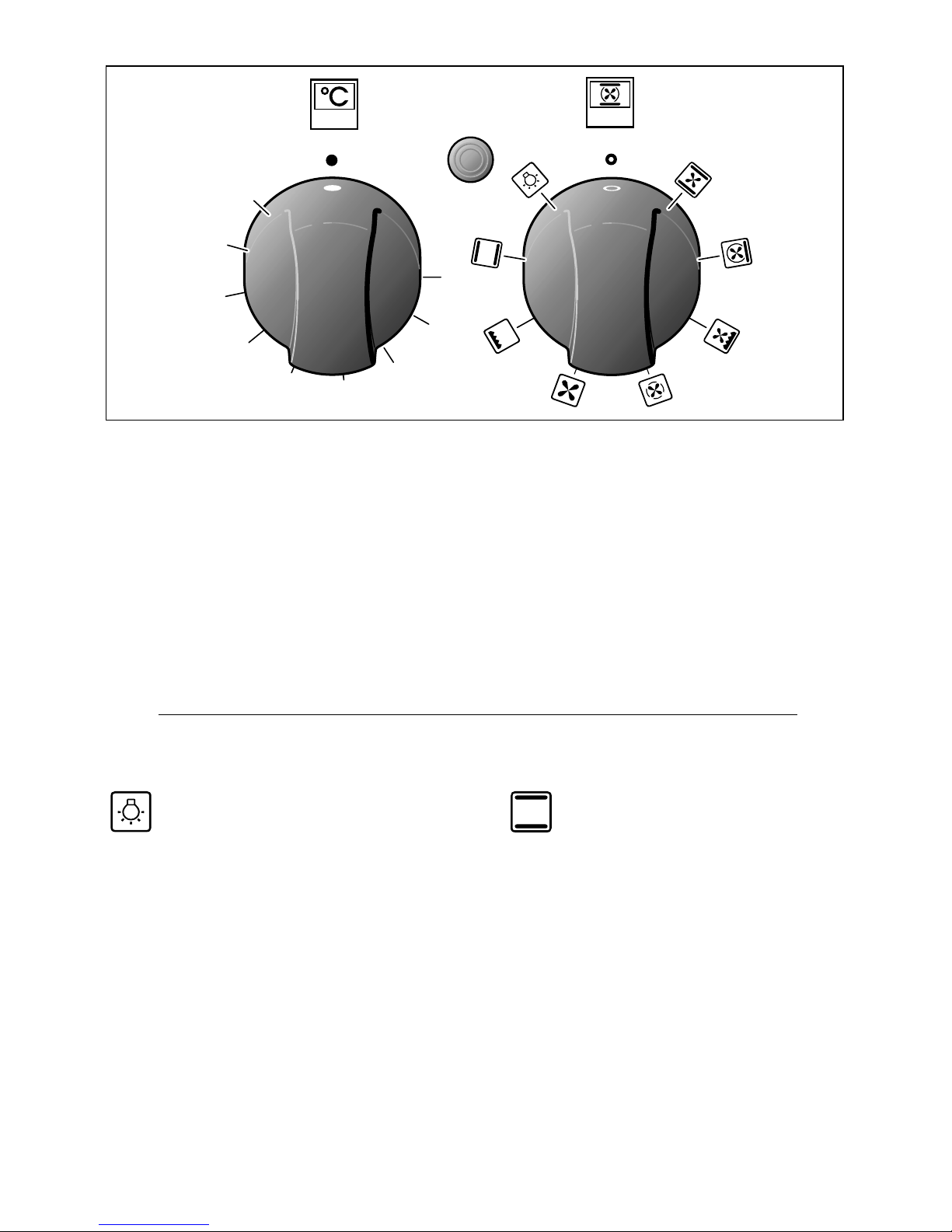
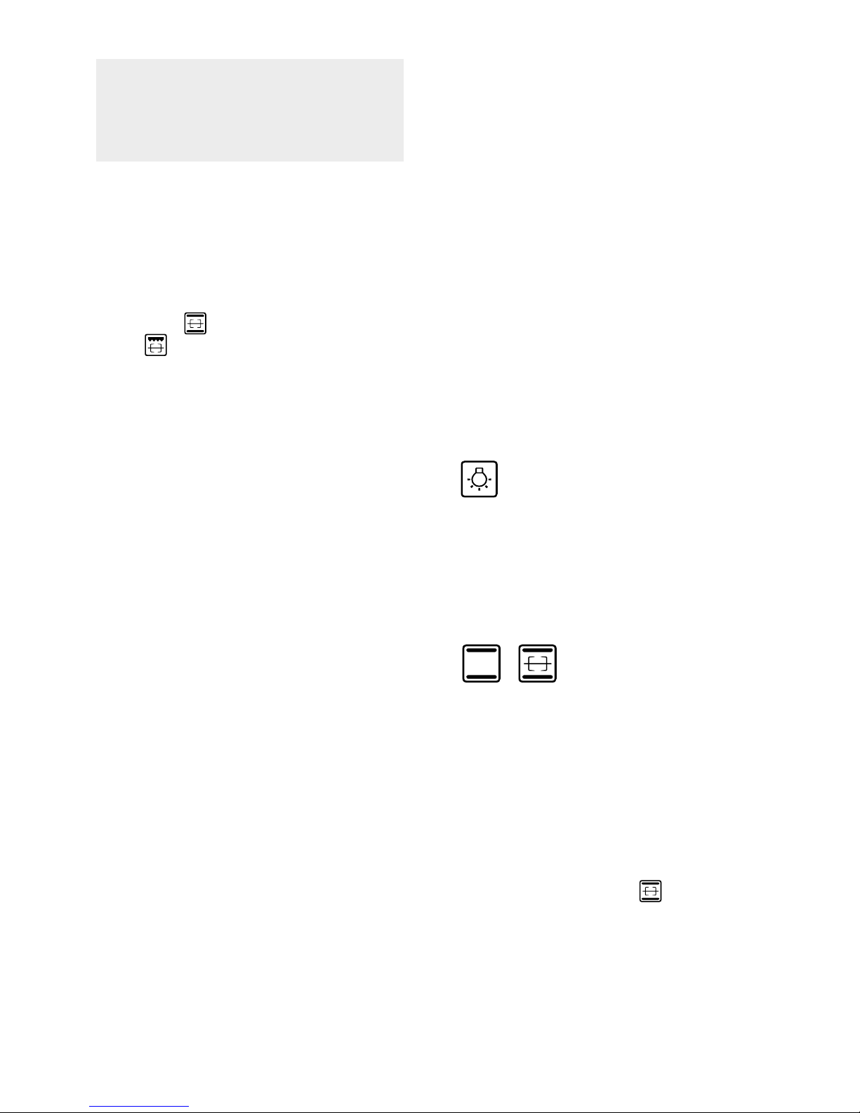
FUNCTION SELECTOR KNOB (fig. 3.2)
Rotate the knob clockwise to set the
oven for one of the following functions:
THERMOSTAT (fig. 3.1)
This only sets the cooking temperature
and does not switch the oven on. Rotate
clockwise until the required temperature
is reached (from 50 to 250).
125
150
175
200
225
100
50
75
250
Fig. 3.1
Fig. 3.2
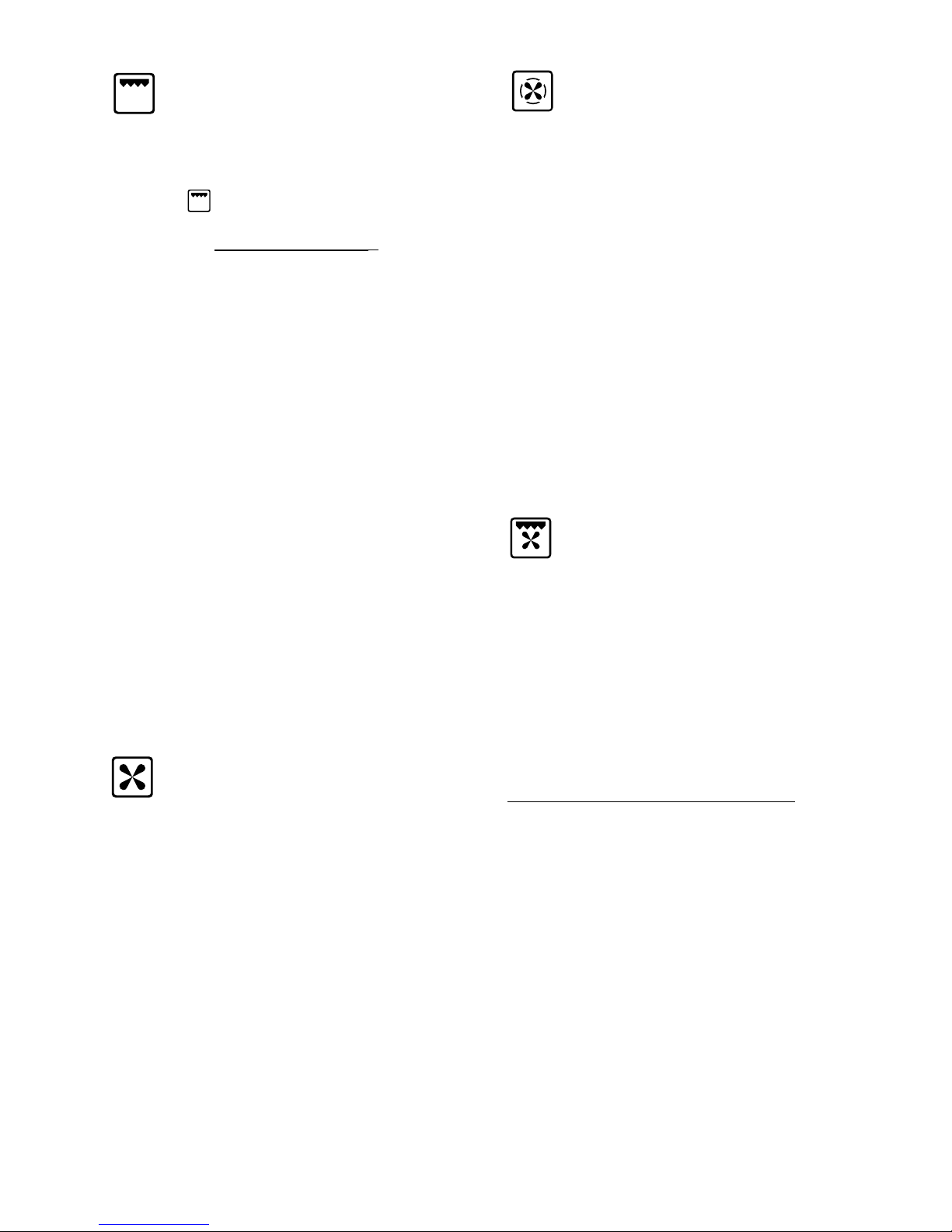
OVEN LIGHT
By turning the knob onto this setting we
light the oven cavity (15 W).
The oven remains alight while any of the
functions is on.
TRADITIONAL CONVECTION
COOKING
The upper and lower heating elements are
switched on. The heat is diffused by natural convection and the temperature must be
regulated between 50° C and 250° C with
the thermostat knob.
It is necessary to preheat the oven before
introducing the foods to be cooked.
Recommended for:
For foods which require the same
cooking temperature both internally and
externally, i. e. roasts, spare ribs,
meringue, etc.
Page 23
23
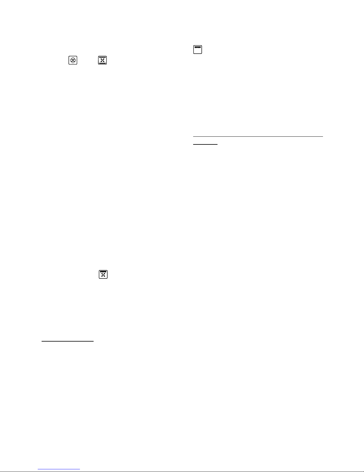
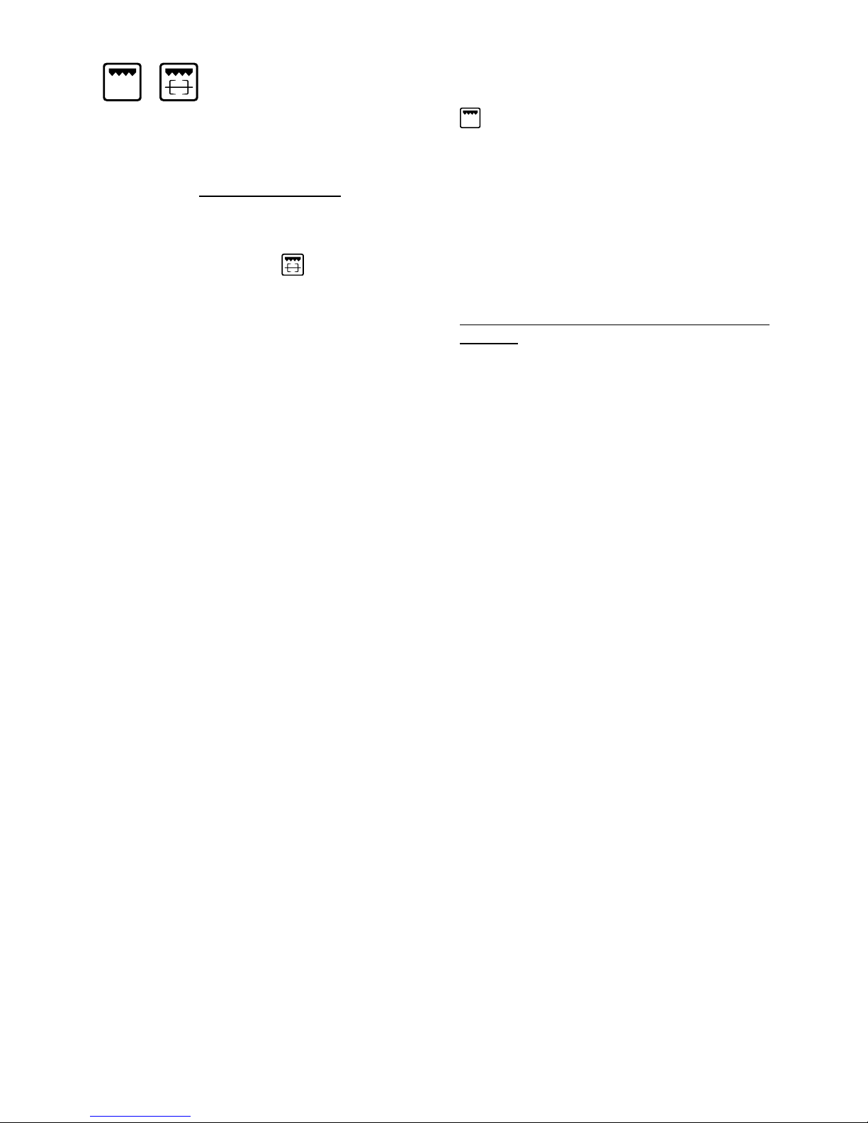
VENTILATED GRILL COOKING
The infra-red ray grill and the fan are on.
The heat is mainly diffused by radiation
and the fan then distributes it throughout
the oven.
The temperature must be regulated
between 50° and 200°C maximum
with the thermostat knob. It is necessary
to preheat the oven for about 5 minutes.
For correct use see chapter “GRILLING
AND AU GRATIN.
Grilling with the oven door closed.
It is recommended that you do not grill
for longer than 30 minutes at any one
time.
ATTENTION: the oven door becomes
very hot during operation.
Keep children away.
Recommended for:
For grill cooking when a fast outside
browning is necessary to keep the juices
in, i. e. veal steak, steak, hamburger, etc.
GRILLING
The infra-red heating element is switched
on. The heat is diffused by radiation.
Use with the function selector knob to
position and the thermostat knob
between 50°C and 225°C maximum
and with the oven door closed
.
For correct use see chapter “USE OF
THE GRILL”
Before using the grill, preheat for about
five minutes.
Always grill with the oven door closed
and do not use the grill for longer
than 30 minutes at any one time.
Caution: The oven door becomes
very hot during operation.
Keep children well out of reach.
Recommended for:
Intense grilling action for cooking with a
broiler; browning, crisping, “au gratin”,
toasting, etc.
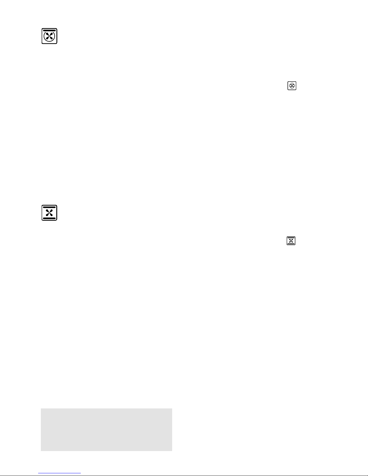
HOT AIR COOKING
The circular element and the fan are on.
The heat is diffused by forced convection and the temperature must be regulated between 50° and 250 °C with the
thermostat knob.
It is not necessary to preheat the oven.
Recommended for:
For foods that must be well done on the
outside and tender or rare on the inside,
i. e. lasagna, lamb, roast beef, whole
fish, etc.
DEFROSTING FROZEN FOODS
Only the oven fan is on. To be used with
the thermostat knob on “●” because the
other positions have no effect. The defrosting is done by simple ventilation without
heat.
Recommended for:
To rapidly defrost frozen foods; 1 kilogram
requires about one hour.
The defrosting times vary according to the
quantity and type of foods to be defrosted.
Page 24
24
The external parts of the oven
become hot during operation.
Keep children well out of reach.
CONVECTION COOKING WITH
VENTILATION
The upper and lower heating elements
and the fan turn on.
The heat coming from the top and bottom is diffused by forced convection.
The temperature must be regulated
between 50° and 250 °C with the thermostat knob.
Recommended for:
For foods of large volume and quantity
which require the same internal and
external degree of cooking; for ie: rolled
roasts, turkey, legs, cakes, etc.
REGENERATION
Set the switch to position and the
thermostat knob to position 150° C.
Bread becomes fragrant again if wet with
a few drops of water and put into the
oven for about 10 minutes at the highest
temperature.
ROASTING
To obtain classical roasting, it is necessary to remember:
– that it is advisable to maintain a tem-
perature between 180 and 200 °C.
– that the cooking time depends on the
quantity and the type of foods.
COOKING ADVICE
STERILIZATION
Sterilization of foods to be conserved, in
full and hermetically sealed jars, is done
in the following way:
a. Set the switch to position .
b. Set the thermostat knob to position
185 °C and preheat the oven.
c. Fill the dripping pan with hot water.
d. Set the jars onto the dripping pan
making sure they do not touch each
other and the door and set the thermostat knob to position 135 °C.
When sterilization has begun, that is,
when the contents of the jars start to
bubble, turn off the oven and let cool.
THAWING AND WARMING UP
The upper element and the circular element connected in series, are switched
on; also the fan is on. The heat is diffused by forced convection with the most
heat being produced by the upper element.
The temperature must be regulated
between 50° and 140 °C with the thermostat knob.
Recommended for:
To keep foods hot after cooking. To
slowly heat already cooked foods.
Page 25
25
GRILLING AND “AU GRATIN”
Grilling may be done by selecting
grill+fan setting with the function
selector knob, because the hot air completely envelops the food that is to be
cooked.
Set the thermostat knob between 50°C
and 200°C maximum and after having
preheated the oven, simply place the
food on the grid.
Close the door
and let the oven operate until grilling is done.
Adding a few dabs of butter before the
end of the cooking time gives the golden
“au gratin” effect.
Grilling with the oven door closed.
It is recommended that you do not
grill for longer than 30 minutes at any
one time.
Attention: the oven door becomes
very hot during operation.
Keep children away.
USE OF THE GRILL
Set the function selector knob to position
and the thermostat knob between
50°C and 225°C maximum.
Leave to warm up for approximately 5
minutes with the door closed.
Introduce the food to be cooked, positioning the grill pan as close to the grill
as possible.
Insert the drip pan under the rack to collect the cooking juices.
Always grill with the oven door
closed.
Grilling with the oven door closed and
not for longer than 30 minutes at any
one time.
Attention: the oven door becomes
very hot during operation.
Keep children away.
SIMULTANEOUS COOKING OF
DIFFERENT FOODS
The MULTI-FUNCTION oven set on
position
and
gives simultaneous
heterogeneous cooking of different foods.
Different foods such as fish, cake and
meat can be cooked together without
mixing the smells and flavours.
This is possible since the fats and vapours
are oxidized while passing through the
electrical element and therefore are not
deposited onto the foods.
The only precautions to follow are:
– The cooking temperatures of the
different foods must be as close to as
possible, with a maximum difference of
20° - 25 °C.
– The introduction of the different dishes
in the oven must be done at different
times in relation to the cooking times of
each one.
The time and energy saved with this type
of cooking is obvious.
OVEN COOKING
Before introducing the food, preheat the
oven to the desired temperature.
For a correct preheating operation, it is
advisable to remove the tray from the
oven and introduce it together with the
food, when the oven has reached the
desired temperature.
Check the cooking time and turn off the
oven 5 minutes before the theoretical
time to recuperate the stored heat.
Page 26
26
44 CONVECTION OVEN (Bottom left oven)
GENERAL FEATURES
The convection oven is equipped with 3
electrical heating elements:
– 2 elements (upper and lower) for nor-
mal oven cooking
– 1 grill element, on the top of the oven,
for grilling which must be done with the
oven door closed.
The input of the elements is:
– Upper element, 1000 W
– Lower element, 1300 W
– Grill element, 2000 W
250
225
125
150
175
200
100
50
75
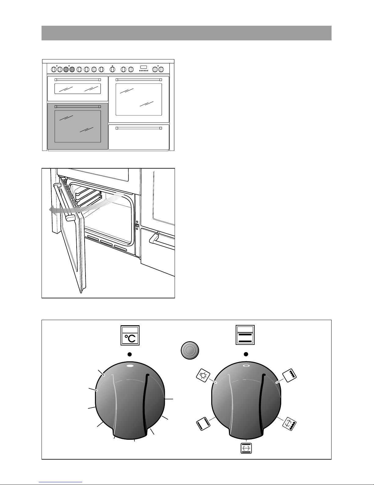
Fig. 4.2 Fig. 4.3
Fig. 4.1
IMPORTANT
To open the bottom left door operate as
indicated in fig. 4.1.
Page 27
27
THERMOSTAT KNOB
(Fig. 4.2)
This only sets the cooking temperature
and does not switch the oven on.
Rotate clockwise until the required temperature is reached (from 50 to 250).
OVEN LIGHT
By turning the knob onto this setting we
light the oven cavity (15 W).
The oven remains alight while any of the
functions is on.
FUNCTION SELECTOR KNOB (fig. 4.3)
Rotate the knob clockwise to set the
oven for one of the following functions:
OPERATING PRINCIPLES
Heating and cooking in the CONVENTIONAL oven are obtained in the following ways:
a. by normal convection
The heat is produced by the upper and
lower heating elements.
b. by radiation
The heat is radiated by the infra red
grill element (use with the oven door
closed.).
The glass on the oven door
reaches high temperatures during operation.
Keep children away.
NOTE:
Upon first use, it is advisable to operate the
oven at the maximum temperature (thermostat knob on position 250) for 60 minutes in
the position and for another 15 minutes
in the mode in order to eliminate any
traces of grease from the electrical resistances.
WARNING:
The door is hot use the handle.
TRADITIONAL
CONVECTION COOKING
The upper and lower heating elements
are switched on. The heat is diffused by
natural convection and the temperature
must be regulated between 50° C and
250° C with the thermostat knob.
It is necessary to preheat the oven
before introducing the foods to be
cooked.
The spit roaster is operated by turning
the selector knob in the mode.
Recommended for:
For foods which require the same cooking temperature both internally and
externally, i. e. roasts, spare ribs,
meringue, etc.
Page 28
28
OVEN COOKING
Before introducing the food, preheat the
oven to the desired temperature.
For a correct preheating operation, it is
advisable to remove the tray from the
oven and introduce it together with the
food, when the oven has reached the
desired temperature.
Check the cooking time and turn off the
oven 5 minutes before the theoretical
time to recuperate the stored heat.
USE OF THE GRILL
Set the function selector knob to position
and the thermostat knob between
50°C and 225°C maximum.
Leave to warm up for approximately 5
minutes with the door closed.
Introduce the food to be cooked, positioning the grill pan as close to the grill
as possible.
Insert the drip pan under the rack to collect the cooking juices.
Always grill with the oven door
closed.
Grilling with the oven door closed and
not for longer than 30 minutes at any
one time.
Attention: the oven door becomes
very hot during operation.
Keep children away.
GRILLING
The infra-red heating element is
switched on. The heat is diffused by
radiation.
Use with the oven door closed
and the
thermostat knob to between 50° and
225°C maximum
The spit roaster is operated by turning
the selector knob in the mode.
For correct use see chapter “USE OF
THE GRILL”
Recommended for:
Intense grilling action for cooking with a
broiler; browning, crisping, “au gratin”,
toasting, etc.
Note: It is recommended that you do
not grill for longer than 30 minutes at
any one time.
Attention: the oven door becomes
very hot during operation. Keep children away
.
Page 29
29
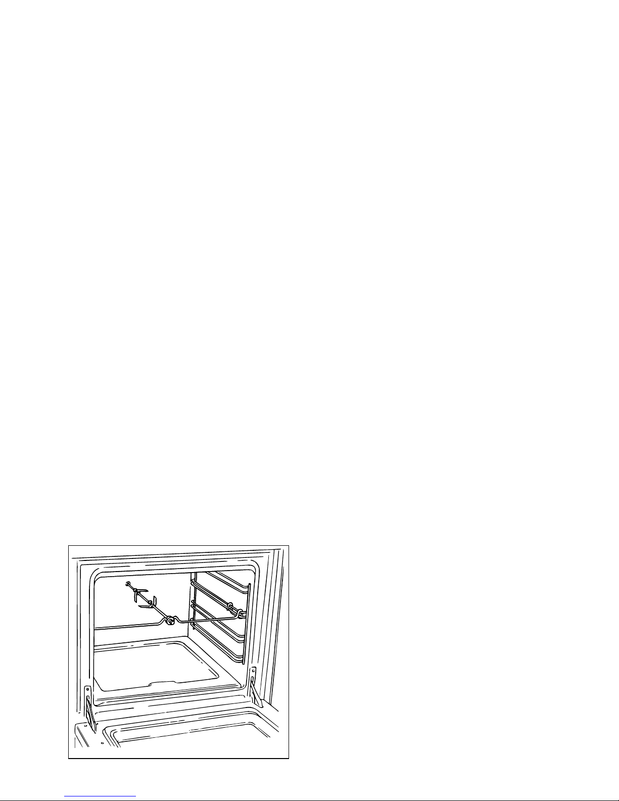
ROTISSERIE (Fig. 4.4)
The oven is equipped with a rotisserie for
cooking on the spit using the grill.
This device is made up of:
– an electrical motor mounted on the
rear part of the oven
– stainless steel spit with a removable
stay-cool handle and two adjustable
sets of prongs
– spit support to be inserted in the
central guide of the oven.
Fig. 4.4
USE OF THE ROTISSERIE (Fig. 4.4)
– Insert the tray into the lowest rack
holders of the oven and insert the rod
support into the intermediate rack
holders.
– Put the meat to be cooked onto the
rod, being careful to secure it in the
center with the special forks.
– Insert the rod into the motor opening
and rest it onto the support of the spit
collar; then remove the grip by turning
it to the left.
– Fit the heat shield and switch on the
grill and turnspit.
The rotation direction of the rotisserie
can be either clockwise or counter-clockwise.
Very important: the rotisserie must
always be used with the oven door
closed.
Attention: the oven door becomes
very hot during operation.
Keep children away.
It is recommended that you do not
grill for longer than 30 minutes at any
one time.
Page 30
30
55 ELECTRICAL CONVECTION OVEN (Top left oven)
The glass on the oven door
reaches high temperatures during operation.
Keep children away.
175
200
75
100
150
125
225
250
MAX
50
Fig. 5.1 Fig. 5.2
The input of the elements is:
– Upper element, 700 W
– Lower element, 1000 W
– Grill element, 2000 W
GENERAL FEATURES
The convection oven is equipped with 3
electrical heating elements:
– 2 elements (upper and lower) for nor-
mal oven cooking
– 1 grill element, on the top of the oven,
for grilling which must be done with the
oven door closed.
NOTE:
Upon first use, it is advisable to operate
the oven at the maximum temperature
(thermostat knob on position MAX) for
60 minutes in the position and for
another 15 minutes in the mode in
order to eliminate any traces of grease
from the electrical resistances.
WARNING:
The door is hot use the handle.
Page 31

31
OPERATING PRINCIPLES
Heating and cooking in the CONVENTIONAL oven are obtained in the following ways:
a. by normal convection
The heat is produced by the upper and
lower heating elements.
b. by radiation
The heat is radiated by the infra red
grill element (use with the oven door
closed.).
FUNCTION SELECTOR KNOB (Fig. 5.2)
Rotate the knob clockwise to set the
oven for one of the following functions.
TRADITIONAL CONVECTION
COOKING
The upper and lower heating elements are
switched on. The heat is diffused by natural convection and the temperature must be
regulated between 50° C and MAX position with the thermostat knob.
It is necessary to preheat the oven before
introducing the foods to be cooked.
Recommended for:
For foods which require the same
cooking temperature both internally and
externally, i. e. roasts, spare ribs,
meringue, etc.
LOWER HEATING ELEMENT
In this position only the lower element is
switched on. Heat is distributed by natural convection. The thermostat can be
set between 50 and 150°C; higher temperatures are not available.
Recommended for:
This mode is particularly suitable to
complete cooking of dishes that require
higher temperature at the bottom.
UPPER HEATING ELEMENT
In this position only the upper element is
switched on. Heat is distributed by natural convection. The thermostat can be
set between 50 and 150°C; higher temperatures are not available.
Recommended for:
This mode is particularly suitable to
complete cooking of dishes that require
higher temperature at the top.
THERMOSTAT KNOB
(Fig. 5.1)
This only sets the cooking temperature
and does not switch the oven on.
Rotate clockwise until the required temperature is reached (from 50°C to MAX).
OVEN LIGHT
The oven is equipped with a light that
illuminates the oven to enable visually
controlling the food that is cooking.
This light is controlled by the selector
knob (fig. 5.2)
It remains on in all the cooking modes.
Page 32

32
USE OF THE GRILL
Leave to warm up for approximately 5
minutes with the door closed.
Place the food inside positioning the rack
as near as possible to the grill.
Insert the drip pan under the rack to collect the cooking juices.
Grilling with the oven door closed.
Grilling with the oven door closed and
do not for longer than 30 minutes at
any one time.
Attention: the oven door becomes
very hot during operation.
Keep children away.
OVEN COOKING
Before introducing the food, preheat the
oven to the desired temperature.
For a correct preheating operation, it is
advisable to remove the tray from the
oven and introduce it together with the
food, when the oven has reached the
desired temperature.
Check the cooking time and turn off the
oven 5 minutes before the theoretical
time to recuperate the stored heat.
GRILLING
The infra-red heating element is
switched on. The heat is diffused by
radiation.
Use with the oven door closed and the
thermostat knob to between 50°C and
200°C.
For correct use see chapter “USE OF
THE GRILL”
Before using the grill, preheat for about
five minutes.
Always grill with the oven door closed
and do not use the grill for longer than
30 minutes at any one time.
Caution: The oven door becomes
very hot during operation.
Keep children well out of reach.
Recommended for:
Intense grilling action for cooking with a
broiler; browning, crisping, “au gratin”,
toasting, etc.
Page 33

33
A
U
T
O
Fig. 6.1
Fig. 6.2
66 ELECTRONIC PROGRAMMER (right oven only)
Description of the buttons:
Timer
Cooking time
End of cooking time
Manual position and cancellation of
the set cooking program
Advance the time for of all pro-
grams
Decrease the program time and
changing the frequency of the audible signal.
The electronic programmer performs the
following functions:
– 24 hours clock with illuminated display
– Timer (up to 23 hours and 59 minutes)
– Program for automatic oven cooking
– Program for semi-automatic oven
cooking.
Description of the illuminated
symbols:
AUTO - flashing - Programmer in auto-
matic position but not programmed
AUTO - always lit - Programmer in auto-
matic position with program set.
Automatic cooking taking place
Timer in operation
and AUTO - flashing - Program
error.
(The time of day lies between the
calculated cooking start and end
time).
Note:
Select a function by the respective button and, in 5 seconds, set the required
time with the / buttons (“onehand” operation).
A power cut makes the clock go to zero
and cancels the set programs.
Page 34

34
Fig. 6.3
A
U
T
O
Fig. 6.4
ELECTRONIC CLOCK(fig. 6.2)
The programmer is equipped with an
electronic clock with an illuminated display which indicates hours and minutes.
Upon immediate connection of the oven
or after a powercut, three zeros will flash
on the display panel.
To set the hour it is necessary to push
the button and then the or
button until you have set the exact hour
(fig. 6.2).
Another way is to simultaneously push
the two buttons and at the same
time push the or button.
Note: The hour setting deletes any program.
ELECTRONIC TIMER
The timer program consists only of a
buzzer which may be set for a maximum
period of 23 hours and 59 minutes.
If the AUTO is flashing push the button.
To set the time, push the button and
the or until you obtain the
desired time in the panel (fig. 6.4).
Having finished the setting, the clock
hour will appear on the panel and the
symbol will be lit.
The countdown will start immediately and
may be seen at any moment on the panel
by simply pressing the button .
At the end of the time, the symbol
will be switched off and an intermittent
buzzer will go off; this can be stopped by
pressing any of the buttons.
SETTING THE FREQUENCY OF THE
AUDIBLE SIGNAL
3 possible sounds can be selected by
pressing the button.
NORMAL COOKING WITHOUT THE
USE OF THE PROGRAMMER
To manually use the oven, that is, without
the aid of the programmer, it is necessary
to cancel the flashing AUTO by pushing
the button (AUTO will be switched off
and the symbol will go on - Fig. 6.3).
Attention: If the AUTO is steadily lit (which
means a cooking program has already
been set), the program can be cancelled
and switched to manual by pushing the
button .
If the oven is switched on, you must
switch off manually.
Page 35

35
A
U
T
O
Fig. 6.5
A
U
T
O
Fig. 6.6
3. Set the temperature and the cooking
program (see the relevant sections).
Once the oven is programmed it will
switch on automatically at the right time
to stop the cooking at the desired end
time.
During cooking, the symbol remains
on.
By pushing the button you can see
the time that remains until the end of
cooking.
The cooking program may be cancelled at any time by pushing .
At the end of the cooking time the oven
will turn off automatically, the symbol
will turn off, AUTO will flash and the buzzer will sound, which can be turned off
by pushing any of the buttons.
Turn the switch and temperature knobs
to "OFF" and put the programmer onto
“manual” by pressing the button.
Attention: A powercut will make the
clock go to zero and will cancel the set
programs.
After a powercut, three zeros will flash
on the panel.
AUTOMATIC OVEN COOKING
To cook food automatically in the oven,
it is necessary to:
1. Set the length of the cooking time
2. Set the end of the cooking time
3. Set the temperature and the oven
cooking program.
These operations are done in the following way:
1.Set the length of time you need to
cook the food by pushing the button and the button to advance, or
to go back if you have passed the
desired time (fig. 6.5). The AUTO and
the symbol will be on.
2.Set the time you need the food to stop
cooking by pushing the button (the
cooking time already added to the
clock time will appear), and the
button (fig. 6.6); if you pass the
desired time you can go back by
pushing the button.
After this setting, the symbol will
go off. If after this setting, the AUTO
flashes on the panel and a buzzer
goes off, it means there was an error
in the programming, that is the the
cooking cycle has been superimposed
on the clock. In this case, change the
end of cooking time or the cooking
time itself by following the instructions
above.
Page 36

36
A
U
T
O
Fig. 6.7
A
U
T
O
Fig. 6.8
At the end of the cooking, the oven and
the symbol will turn off, the AUTO will
flash and a buzzer will go off which can
be stopped by pushing any of the buttons.
Turn the switch and temperature knobs
to "OFF" and put the programmer onto
“manual” by pressing the button.
SEMI - AUTOMATIC COOKING
This is used to switch the oven off automatically after the desired cooking time
has elapsed.
There are two ways to set the semiautomatic cooking function:
1.Set the length of time you need to
cook the food by pushing the button and the button to advance, or
to go backwards (Fig. 6.7).
This sets the desired “stop” time.
or
2.Set the time you need the food to stop
cooking by pushing the button and
the button to advance, or to go
backwards if you have passed the
desired time (Fig. 6.8).
AUTO and the symbol will be on.
Then set the temperature and the cooking program (see the relevant sections).
The oven is switched on and it will
switch off automatically at the end of the
desired time.
During cooking, the symbol remains
on and by pressing the button you
can see the time that remains until the
end of the cooking.
The cooking program can be cancelled at any moment by pushing the
button.
Page 37

37
77 CLEANING AND MAINTENANCE
CLEANING THE VITROCERAMIC
COOKING HOB
– See page 18.
CLEANING THE CERAMIC GRIDDLE
– See page 20.
GENERAL ADVICE
– When the appliance is not being
used, it is advisable to keep the gas
tap closed.
– Every now and then check to make
sure that the flexible tube that connects the gas line or the gas cylinder
to the appliance is in perfect condition
and eventually substitute it if it shows
signs of wearing or damage.
– The periodical lubrication of the gas
taps must be done only by specialized
personnel.
– If a tap becomes stiff, do not force;
contact your local After Sales Service
Centre.
– Important:
Before any operation of cleaning
and maintenance disconnect the
appliance from the electrical network.
Attention
The appliance gets very hot, mainly
around the cooking areas. It is very
important that children are not left
alone in the kitchen when you are
cooking.
Do not use a steam cleaner
because the moisture can get into
the appliance thus make it unsafe.
ENAMELLED PARTS
All the enamelled parts must be cleaned
with a sponge and soapy water or other
non-abrasive products.
Dry preferably with a soft cloth.
Acidic substances like lemon juice,
tomato sauce, vinegar etc. can damage
the enamel if left too long.
STAINLESS STEEL SURFACES
(COATED)
The stainless steel front panels on this
cooker (facia, oven doors, drawer) are
protected by a finger-print proof lacquer.
To avoid damaging this lacquer, do not
clean the stainless steel with abrasive
cleaners or abrasive cloths or scouring
pads.
ONLY SOAPY/WARM WATER MUST
BE USED TO CLEAN THE (COATED)
STAINLESS STEEL SURFACES.
STAINLESS STEEL SURFACES
(UNCOATED)
The hob + sides are made from uncoated stainless steel.
Can be cleaned with an appropriate
stainless steel cleaner.
Page 38

38
Fig. 7.1
Fig. 7.2
S
F
C
T
BURNERS
T
hey can be removed and washed with
soapy water only.
They will remain always perfect if
cleaned with products used for silverware.
After cleaning or wash, check that burner-caps and burner-heads are dry before
placing them in the respective hous-
ings.
It is very important to check that the
burner flame distributor and the cap has
been correctly positioned - failure to do
so can cause serious problems.
Note: To avoid damage to the electric
ignition do not use it when the burners are not in place.
CORRECT REPLACEMENT OF THE
BURNERS
It is very important to check that the
burner flame distributor F and the cap C
has been correctly positioned (see fig.
7.1-7.2) - failure to do so can cause a
poor burner flame and/or damage to the
burner and hob.
Check that the electrode “S” (fig. 7.1) is
always clean to ensure trouble-free
sparking.
Check that the probe T (fig. 7.1) next to
each burner is always clean to ensure
correct operation of the safety valves.
Both the probe and ignition plug must be
very carefully cleaned.
GAS TAPS
In the event of operating faults in the gas
taps, call the After Sales Service
Department.
The burners become very hot during
operation.
Keep children away.
Page 39

39
Fig. 7.5
Fig. 7.3
Fig. 7.4
A
B
TRIPLE RING BURNER
The triple ring burner must be correctly positioned (see fig. 7.5); the burner rib must be
enter in their logement as shown by the arrow see fig. 7.3).
Then position the cap A and the ring B (fig. 7.4 - 7.5).
The burner correctly positioned must not rotate (fig. 7.4).
Page 40

40
1
2
Fig. 7.8
Fig. 7.6
Fig. 7.7
ASSEMBLY AND DISMANTLING OF
THE SIDE RUNNER FRAMES
– Assemble the wire racks to the oven
walls using the 2 screws (Fig. 7.6).
– Slide the tray and rack into the runners
fig. 7.7.
The rack must be fitted so that the
safety catch, which stops it sliding out,
faces the inside of the oven.
– To dismantle, operate in reverse
order.
REPLACING THE OVEN LIGHT
Before any maintenance is started
involving electrical parts of the appliance,
it must be disconnected from the power
supply.
– Let the oven cavity and the heating
elements cool down;
– Switch off the electrical supply;
– Unscrew the protective cover (fig. 7.8);
– Unscrew and replace the bulb with a
new one suitable for high temperatures
(300°C) having the following specifica-
tions: 230-240V 50 Hz, 15W, E14
– Refit the protective cover
NOTE: Oven bulb replacement is not
covered by your guarantee
Page 41

41
Do not store flammable material in
the oven or in the drawer.
INSIDE OF OVEN
This must be cleaned regularly.
Remove and refit the side runner frames
as described on the next chapter.
With the oven warm, wipe the inside
walls with a cloth soaked in very hot
soapy water or another suitable product.
Side runner frames, tray and rack can
be removed and washed.
Fig. 7.9
DRAWER
The drawer (fig. 7.9) comes out like a
normal drawer.
REMOVING THE BOTTOM LEFT OVEN
DOOR
The oven door can easily be removed as
follows:
– Open the door.
– Unscrew the 4 screws of the bottom
hinge (fig. 7.11)
– Hold the door and unscrew the 3
screws of the upper hinge (fig. 7.10).
– Remove the door following the arrow C
(fig. 7.10 - 7.11)
– Rest the door on a soft surface.
– To replace the door, repeat the above
steps in reverse order.
Fig. 7.10
Fig. 7.11
c
c
Page 42

42
Fig. 7.12
B
A
C
Fig. 7.12d
Fig. 7.12c
Fig. 7.12b
Fig. 7.12a
REMOVING THE OVEN DOOR
The oven door can easily be removed as
follows:
– Open the door to the full extent (fig.
7.12a).
– Open the lever “A” completely on the
left and right hinges (fig. 7.12b).
– Hold the door as shown in fig. 7.12.
– Gently close the door (fig. 7.12) until
left and right hinge levers “A” are
hooked to part “B” of the door (fig.
7.12b)
– Withdraw the hinge hooks from their
location following arrow “C” (fig.
7.12d).
– Rest the door on a soft surface.
– To replace the door, repeat the above
steps in reverse order.
Page 43

43
Advice for the installer
IMPORTANT
– Cooker installation must only be carried out by QUALIFIED TECHNICIANS and in
compliance with local safety standards. Failure to observe this rule will invalidate the
warranty.
The appliance must be installed in compliance with regulations in force in your country
and in observation of the manufacturer's instructions.
– Always unplug the appliance before carrying out any maintenance operations or
repairs.
– The surfaces of adjacent furniture and walls must be capable of withstanding tempera-
tures in excess of 75˚C. If the cooker is installed adjacent to furniture which is higher
than the gas hob cooktop, a gap of 50 cm must be left between the side of the cooker
and the furniture.
– Some appliances are supplied with a protective film on steel and aluminium parts.
This film must be removed before using the cooker.
Page 44

44
200 mm
650 mm
500 mm
450 mm
Fig. 8.2a
■ Class 1
Gas connection
made using rubber
hose which must be
visible and easily
inspected or using
rigid or flexible metal
pipe.
88 INSTALLATION
LOCATION
The appliance must be kept no less than 50 mm away from any side wall which exceed
the height of the hob surface (fig. 8.2a - 8.2b).
The appliance must be housed in heat resistant units.
The walls of the units must be capable of resisting temperatures of 75 °C above
room temperature.
Do not install the appliance near inflammable materials (eg. curtains).
If the cooker is located on a pedestal it is necessary to provide safety measures to prevent falling out.
Before installing the cooker level the appliance by screwing or unscrewing the six
adjustable feet fitted below.
WARNING!
For safety reasons unscrew
the feet (from screwed position) to the maximum extent of
5 mm (fig. 8.1).
Fig. 8.1
Page 45

45
BACKGUARD
• Assemble the backguard
as shown in figure 8.3
and fix it by the 5
screws “A”.
Fig. 8.3
A
200 mm
650 mm
500 mm
450 mm
Fig. 8.2b
Gas connection
made using rigid or
flexible metal pipe.
■ Class 2
■ Subclass 1
Page 46

46
Fig. 8.4
Fig. 8.5
Fig. 8.6
MOVING THE COOKER
WARNING
To move the cooker always ensure
two people carry out this manoeuvre
to prevent damage to the appliance
(fig. 8.4).
WARNING
Be carefull: do not lift the cooker by
the door handle (fig. 8.5).
WARNING
When moving cooker to its final position
DO
NOT DRAG (fig. 8.6).
Lift feet clear of floor (fig. 8.4).
Page 47

47
DISCHARGING PRODUCTS OF
COMBUSTION
Extractor hoods connected directly to
the outside must be provided, to allow
the products of combustion of the gas
appliance to be discharged (fig. 8.7).
If this is not possible, an electric fan may
be used, attached to the external wall or
the window; the fan should have a
capacity to circulate air at an hourly rate
of 3-5 times the total volume of the
kitchen (fig. 8.8).
The fan can only be installed if the room
has suitable vents to allow air to enter,
as described under the heading
“Choosing suitable surroundings”.
This appliance is not connected to a
device to evacuate the combustion
products. This must be installed and
connected in conformity with the
installation rules in force.
Pay special care to room ventilation as
well.
CHOOSING SUITABLE SURROUNDINGS
In the room chosen to accommodate the
gas appliance, there must be an adequate natural draft to allow combustion
of the gas.
The natural draft must be produced
directly by one or more vents made in
the external walls and providing a total
opening of at least 100 cm
2
.
The vents must be positioned close to
the floor, preferably on the opposite side
to the combustion discharge outlet and
must be designed in such a way that
they cannot be obstructed either from the
inside or the outside.
When it is not possible to provide the
necessary vents, the draft may be supplied from an adjacent room, ventilated
in the required manner, provided it is not
a bedroom or an area at risk.
In this event, the door of the kitchen
must be opened to allow the draft to
enter the room.
There must be a distance of at least 650
mm between the hob of the cooker and
any wall cupboard or extractor hood
positioned immediately above (see fig.
8.7).
H min 650 mm
Air vent
Extractor hood
for products of
combustion
Fig. 8.7
Fig. 8.8
Air vent
Electric fan to
extract products
of combustion
Page 48

48
99 GAS SECTION
GASES
Cat: II2H3+
The gases used for the operation of
cooking appliances may be grouped by
their characteristics into two types:
✓G 20 20 mbar
✓ G 30/ G31 28-30/37 mbar
GB
The walls adjacent to the cooker
must be of material resistant to heat.
Before installation, make sure that
the local distribution conditions
(type of gas and its pressure) and
the adjustment of this appliance
are compatible. The appliance
adjustment conditions are given on
the plate or the label.
GAS CONNECTION
The connection must be executed by a
qualified technician according to the relevant standards.
The appliance is predisposed and calibrated to operate with the gas indicated
on the specifications plate.
Ensure that the room in which the cooker is to be installed is adequately ventilated, in compliance with applicable regulations.
Connection to the gas supply pipe or
gas cylinder must be made in accordance with the requirements of the
applicable regulations.
Fig. 9.1bFig. 9.1a
gas pipe
cooker
rear protection
The gas supply must be connected to
the gas inlet which is located at the rear
of the appliance as illustrated in the
figures 9.1a or 9.1b.
If the connection pipe cross the cooker,
it must be positioned under the cooker
rear protection (fig. 9.1a).
Page 49

49
IMPORTANT:
The gasket “D” (fig. 9.3) is the element
that guarantees the seal in the gas connection. It is recommended that it be
replaced whenever it shows even the
slightest deformation or imperfection.
In particular, make sure that:
– the flexible hose does not come into
contact with any parts of the cooker
with surface temperatures in excess of
70˚K;
– flexible hose does not come into
contact with sharp edges or corners;
– the hose is not under tension or
twisted and is not kinked or too tightly
bent;
– the connection with rigid metal pipes
should not cause stresses to the gas
ramp.
– we advise replacing the gasket on the
slightest sign of deformation or imperfection.
– the hose can easily be inspected
along its entire length to check its
condition; hoses should replaced after
a maximum of three years.
– the cylinder cock or the supply cock
immediately ahead of the appliance is
closed whenever the cooker is not in
use.
Fig. 9.2
IMPORTANT:
To replace hose connector or to screw
the connecting tube it is necessary to
operate with 2 spanners (fig. 9.2).
After connecting to the mains, check
that the couplings are correctly
sealed, using soapy solution, but
never a naked flame.
The fitting (fig. 9.3) is made up of:
A - Gas train terminal fitting
B - Hose connector for G30/G31 gas
C - Hose connector for G20 gas
D - Gasket
E - Conical union
D
A
B
C
Fig. 9.3
IMPORTANT: (only for England)
Before connecting to the gas remove
the reduction “B” or “C” on the appliance and mount the conical union
“E” supplied.
E
Page 50

50
GAS MAINTENANCE
REPLACEMENT OF BURNER
INJECTORS
If the injectors are not supplied they
can be obtained from the “Service
Centre”.
Select the injectors to be replaced
according to the “Table for the choice of
the injectors”.
To replace the injectors proceed as follows:
- Remove pan supports and burners
from the cooktop.
- Using a wrench, substitute the nozzle
injectors “J” (fig. 9.4a, 9.4b) with those
most suitable for the kind of gas for
which it is to be used.
The burners are conceived in such a
way so as not to require the regulation of the primary air.
Fig. 9.4a
J
J
Fig. 9.4b
Page 51

51
ADJUSTING OF THE MINIMUM OF
THE TOP BURNERS
In the minimum position the flame must
have a length of about 4 mm and must
remain lit even with a quick turn from the
maximum position to that of minimum.
The flame adjustment is done in the following way:
– Turn on the burner
– Turn the tap to the MINIMUM position
– Take off the knob
– With a thin screwdriver pass by the
hole of microswitch and turn the screw
F until adjustment is correct (fig. 9.5).
Normally for G30/G31, tighten up the
regulation screw.
F
Fig. 9.5
IMPORTANT
All intervention regarding installa-
tion maintenance and conversion
of the appliance must be fulfilled
with original factory parts.
The manufacturer declines any
liability resulting from the noncompliance of this obligation.
LUBRICATION OF THE GAS TAPS
The operations must be executed by a
qualified technician.
Page 52

52
TABLE FOR THE CHOICE OF THE INJECTORS
INCREASE OF AIR NECESSARY FOR GAS COMBUSTION (2 m
3
/h x kW)
BURNERS Air necessary for combustion [m
3
/h]
Auxiliary (A) 2,00
Semi-rapid (SR) 3,50
Rapid (R) 6,00
Triple-ring (TR) 7,00
BURNERS
Auxiliary (A) 1,00 0,30 50 72 (X)
Semi-rapid (SR) 1,75 0,45 65 97 (Z)
Rapid (R) 3,00 0,75 85 115 (Y)
Triple-ring (TR) 3,50 1,50 95 135 (T)
Nominal
Power
[kW]
Reduced
Power
[kW]
Ø injector
[1/100 mm]
Ø injector
[1/100 mm]
G 20
20 mbar
G 30 - 28-30 mbar
G 31 - 37 mbar
Cat: II 2H3+
GB
Page 53

53
IMPORTANT: The cooker must be
installed in accordance with the
manufacturer’s instructions.
Incorrect installation, for which the
manufacturer accepts no responsibility, may cause injury to persons or
animals etc.
The connection of the appliance to
the grounding unit is mandatory.
The manufacturer declines every
responsability for any inconvenience resulting from the inobservance of this condition.
GENERAL
– Connection to the mains must be car-
ried out by qualified personnel in
accordance with current regulations.
– The appliance must be connected to
the mains checking that the voltage
corresponds to the value given in the
rating plate and that the electrical
cable sections can withstand the load
specified on the plate.
– The cooker can be connected directly
to the mains placing an omnipolar
switch with minimum opening
between the contacts of 3 mm
between the appliance and the mains.
– The power supply cable must not
touch any hot parts and must be positioned so that it does not exceed 75°C
at any point.
– Once the cooker has been installed,
the switch or socket must always be
accessible.
N.B. For connection to the mains, do
not use adapters, reducers or branching devices as they can cause overheating and burning.
If the installation requires alterations to
the domestic electrical system or if the
socket and appliance plug are incompatible, call an expert.
He should also check that the socket
cable section is suitable for the power
absorbed by the appliance.
1100 ELECTRICAL SECTION
Before effecting any intervention
on the electrical parts the appliance must be disconnected from
the network.
Page 54

54
CONNECTING THE FEEDER CABLE
To connect the feeder cable to the cooker
it is necessary to:
– Remove the 6 screws that hold shield
A behind the cooker.
– Open completely the cable clamp D.
– Position the U bolts onto terminal block
B (fig. 10.1) according to the diagram
in fig. 10.2 and fig. 10.3.
– Insert the feeder cable into the cable
save P. The supply cable must be of a
suitable size for the current requirements of the appliance; see the
section “Feeder cable section”.
– Connect the phase and earth cables to
terminal B according to figures 10.2
and 10.3.
– Pull the feeder cable and block it with
the cable clamp D
– Re-mount shield A.
N.B. The earth conductor must be left
about 3 cm longer than the others.
Fig. 10.1
PE
12345
N (L2)L1
230 V
FEEDER CABLE SECTION
“TYPE H05RR-F”
Mod. 136 EX 634
230V 3 x 4 mm2(*) (**)
Mod.
136 EX 636
230V 3 x 4 mm2(*) (**)
Mod.
136 EX 838
230V 3 x 4 mm2(**)
(**) Connection with wall box connection.
(*) Diversity factor applied
23451
230 V ~
N
(L
2
)
PE
L1
Red
or
Brown
(Live)
Black
or
Blue
(Neutral)
Green
and
Yellow
(Earth)
Fig. 10.3
PE Earth
N Neutral
L Live
P
D
A
B
Fig. 10.2
Page 55

55
Mode d’emploi
Français
Cher Client
Vous venez d’acquérir une de nos cuisinières et nous
vous remercions de votre choix.
Celle-ci a été soigneusement conçue, fabriquée et tes-
tée pour votre plus grande satisfaction.
Pour être à même de l’utiliser dans les meilleures
conditions et pour obtenir ce que vous êtes en droit d’en
attendre, nous vous conseillons de lire très attentivement
cette NOTICE D’UTILISATION.
Les instructions et les conseils qu’elle contient vous aideront efficacement à découvrir toutes les qualités de votre
nouvel appareil.
Cette cuisinière devra être destinée seulement à l’utilisation
pour laquelle elle a été conçue, c’est-à-dire la cuisson des aliments.
Toute autre utilisation doit être retenue incorrecte et dangereuse.
Nous déclinons toute responsabilité en cas de dommages
occasionnés par l’utilisation incorrecte, erronée ou irrationnelle de l’appareil.
FR
Déclaration de conformité CE
Cette cuisinière a été conçue, fabriquée et mise sur le marché en conformité avec les:
- Prescriptions relatives à la sécurité de la Directive "Gaz" 90/396/CEE;
- Prescriptions relatives à la sécurité de la Directive "Basse Tension" 73/23/CEE;
- Prescriptions relatives à la protection de la Directive "EMC" 89/336/CEE
;
- Prescriptions de la Directive 93/68/CEE.
Page 56

56
CONSEILS POUR L’UTILISATEUR
• Pendant et immédiatement après le
fonctionnement certaines parties de la
cuisinière atteignent des températures
très élevées. Eviter de les toucher.
• Tenir les enfants éloignés de l'appareil,
surtout lorsqu'il est en fonction.
• Après avoir utilisé la cuisinière, vérifier
que l'index des manettes est sur la
position de fermeture et fermer le robinet principal de la conduite d'alimentation en gaz ou le robinet de la bonbonne.
• En cas d'anomalies de fonctionnement
des robinets gaz, appeler le Service
Après-Vente.
Risque d'incendie!
• Ne placer aucun matériau inflammable sur la table de cuisson ou
dans les fours ou le tiroir.
• Vérifier que les fils électriques
d’autres appareils, utilisés dans le
voisinage, ne puissent pas venir au
contact de la table de cuisson.
• Ne jamais cuisiner directement sur
la table vitrocéramique, mais dans
des marmites ou des récipients.
AVERTISSEMENTS ET CONSEILS
IMPORTANTS POUR L’UTILISATION
DES APPAREILS ELECTRIQUES
L’utilisation d’un appareil électrique
comporte l’observance de certaines précautions fondamentales.
En particulier:
– éviter de toucher l’appareil les mains
ou pieds mouillés
– éviter l’utilisation de l’appareil les
pieds nus
– éviter l’utilisation de l’appareil aux
enfants ou aux incapables, sans surveillance.
Le constructeur décline toute responsabilité en cas de dommages occasionnés
par une utilisation incorrecte, erronée ou
irrationnelle.
IMPORTANT:
Cet appareil a été projeté et construit uniquement pour la cuisson des mets domestiques (électroménagers) et il n'est pas apte à une utilisation non domestique donc il
ne peut pas être utilisé dans une local commercial.
La garantie disparaît si l'appareil est utilisé dans une local non domestique c'est-àdire dans une local semi-commercial, commercial ou communautaire.
Page 57

57
AVERTISSEMENTS ET CONSEILS
IMPORTANTS
Après le déballage, s’assurer de l’intégrité de l’appareil.
En cas de doute, éviter son utilisation et
s’adresser au revendeur ou appeler un
technicien qualifié.
Les pièces de l’emballage (sacs plastique, polystyrène, clous, feuillard etc.)
ne doivent pas être laissées à la portée
des enfants car sources potentielles de
danger.
– Ne pas essayer de modifier les carac-
téristiques techniques de l’appareil car
il peut être dangereux.
– Ne pas effectuer le nettoyage ou l’en-
tretien sans avoir préalablement
débranché l’appareil.
– Ne pas recouvrir de feuilles d’alumi-
nium les parois du four. Ne pas poser
de plaques à pâtisserie, ni de lèchefrites sur la sole du four.
– Lorsque vous décidiez de ne plus uti-
liser cet appareil ou bien si vous voulez éliminer votre ancien appareil,
avant de vous en débarrasser, il est
récommandé de le rendre inutilisable
dans la façon prévue par les normes
en vigueur en matière de protection
de la santé et de l’environnement. Les
parties susceptibles de constituer un
danger pour les enfants doivent être
rendues inoffensives.
– L’utilisation d’un appareil de cuisson
au gaz produit de la chaleur et de l’humidité dans les locaux où celui-ci est
installé.
Veiller à ce que le local soit bien
aéré: garder les bouches de ventilation naturelle ouvertes ou installer
une hotte d’aspiration équipée d’un
conduit d’évacuation.
– L’usage intensif et prolongé de cet
appareil peut nécessiter une aération
supplémentaire, comme par exemple
l’ouverture d’une fenêtre, ou une aération plus efficace, comme l’augmentation de la puissance d’aspiration
mécanique s’il y en a une.
PREMIERE UTILISATION DU FOUR
Il est conseillé de suivre ces instructions:
• Equiper l’intérieur du four en montant
les grilles latérales, comme décrit
dans le chapitre “
NETTOYAGE ET
ENTRETIEN
”.
• Introduire grilles et lèchefrite
• Allumer le four vide à la puissance
maximale pour éliminer les traces de
graisse des éléments chauffants.
• Nettoyer l’intérieur du four avec un
chiffon imprégné d’eau et de détergent neutre. Puis essuyer parfaitement.
– Lisez les instructions avec la plus
grande attention avant de procéder à
l’installation et à l’utilisation de l’appareil.
ATTENTION: cet appareil doit être
installé dans un local pourvu d’une
ventilation continue, conformément
aux normes en vigueur.
Page 58

58
11 TABLE DE TRAVAIL
TABLE DE TRAVAIL
1. Brûleur auxiliaire (A) 1,00 kW
2. Brûleur semirapide (SR) 1,75 kW
3. Brûleur rapide (R) 3,00 kW
4. Brûleur triple couronne (TC) 3,50 kW
5
. Zone de cuisson hi-light
Ø 180 1800 W
6.
Zone de cuisson hi-light
Ø 145 1200 W
136 EX 634
Cuisinière: Cat: II 2E+3+
REMARQUE:
✓ L’appareil est équipé d’allumage électronique incorporé dans les manettes.
✓ L’appareil est équipé d’un système de sécurité, la sortie du gaz est bloquée, si la
flamme venait à s’éteindre accidentellement.
✓ Attention:
Dès que l’on remarque une fente sur les
zones de cuisson vitrocéramiques
,
débrancher immédiatement l’appareil et appeler le Service Après -Vente.
Fig. 1.1a
2
3
4
4
1
2
5
6
Page 59

59
TABLEAU DE BORD
136 EX 634
Fig. 1.1b
A
U
T
O
12345 7689101112 14 15
13
1619 18 1720
21
DESCRIPTION DES COMMANDES
1.
Manette commande thermostat four
électrique
(four
supérieur à
gauche
)
2.
Manette commande sélecteur de fonctions four
électrique
(four
supérieur à
gauche
)
3.
Manette commande thermostat four
électrique
(four
inférieur à
gauche
)
4.
Manette commande sélecteur de fonctions four
électrique
(four
inférieur à
gauche
)
5.
Manette commande brûleur
triple couronne
avantà gauche
(1)
6.
Manette commande brûleur
semirapide
arrièreà gauche
(2)
7.
Manette commande brûleur
rapide
arrière
centrale à
gauche
(3)
8.
Manette commande brûleur
auxiliaire
avant
centrale à
gauche
(1)
9.
Manette commande
zone de cuisson
avant
centrale à
droite
(6)
10.
Manette commande
zone de cuisson
arrière
centrale à
droite
(5)
11.
Manette commande brûleur
semirapide
arrièreà droite
(2)
12.
Manette commande brûleur
triple couronne
avantà droite
(4)
13. Programmateur électronique (début/fin de cuisson)
(seulement pour le four à droit)
14.
Manette commande thermostat four
multifonctions
(four à droit)
15. Manette commande sélecteur de fonctions four
multifonctions
(four à droit)
16. Témoin de fonctionnement
(four à droit)
17.
Témoin
d’indication de la chaleur
résiduelle zone de cuisson
arrière
18.
Témoin
de fonctionnement zones de cuisson hi-light
19.
Témoin
d’indication de la chaleur
résiduelle zone de cuisson
avant
20. Témoin de fonctionnement (
four
inférieur à
gauche
)
21. Témoin de fonctionnement (
four
supérieur à
gauche
)
Page 60

60
TABLE DE TRAVAIL
TABLE DE TRAVAIL
1. Brûleur auxiliaire (A) 1,00 kW
2. Brûleur semirapide (SR) 1,75 kW
3. Brûleur rapide (R) 3,00 kW
4. Brûleur triple couronne (TC) 3,50 kW
5. Grill en vitrocéramique 1300 W
136 EX 636
REMARQUE:
✓ L’appareil est équipé d’allumage électronique incorporé dans les manettes.
✓ L’appareil est équipé d’un système de sécurité, la sortie du gaz est bloquée, si la
flamme venait à s’éteindre accidentellement.
✓ Attention:
Dès que l’on remarque une fente sur le gril en vitrocéramique, débrancher
immédiatement l’appareil et appeler le Service Après -Vente.
Cuisinière: Cat: II 2E+3+
Fig. 1.2a
2
3
4
4
1
2
5
Page 61

61
TABLEAU DE BORD
136 EX 636
DESCRIPTION DES COMMANDES
1.
Manette commande thermostat four
électrique
(four
supérieur à
gauche
)
2.
Manette commande sélecteur de fonctions four
électrique
(four
supérieur à
gauche
)
3.
Manette commande thermostat four
électrique
(four
inférieur à
gauche
)
4.
Manette commande sélecteur de fonctions four
électrique
(four
inférieur à
gauche
)
5.
Manette commande brûleur
triple couronne
avantà gauche
(1)
6.
Manette commande brûleur
semirapide
arrièreà gauche
(2)
7.
Manette commande brûleur
rapide
arrière
centrale à
gauche
(3)
8.
Manette commande brûleur
auxiliaire
avant
centrale à
gauche
(1)
9.
Manette commande
grill en vitrocéramique (5)
10.
Manette commande brûleur
semirapide
arrièreà droite
(2)
11.
Manette commande brûleur
triple couronne
avantà droite
(4)
12. Programmateur électronique (début/fin de cuisson)
(seulement pour le four à droit)
13.
Manette commande thermostat four
multifonctions
(four à droit)
14. Manette commande sélecteur de fonctions four
multifonctions
(four à droit)
15. Témoin de fonctionnement
(four à droit)
16.
Témoin
de fonctionnement grill en vitrocéramique
17. Témoin de fonctionnement (
four
inférieur à
gauche
)
18. Témoin de fonctionnement (
four
supérieur à
gauche
)
Fig. 1.2b
A
U
T
O
12345 76891011 1314
12
151617
18
Page 62

62
TABLE DE TRAVAIL
TABLE DE TRAVAIL
1. Brûleur auxiliaire (A) 1,00 kW
2. Brûleur semirapide (SR) 1,75 kW
3. Brûleur rapide (R) 3,00 kW
4. Brûleur triple couronne (TC) 3,50 kW
136 EX 838
REMARQUE:
✓ L’appareil est équipé d’allumage électronique incorporé dans les manettes.
✓ L’appareil est équipé d’un système de sécurité, la sortie du gaz est bloquée, si la
flamme venait à s’éteindre accidentellement.
Cuisinière: Cat: II 2E+3+
Fig. 1.3a
2
3
3
4
4
1
1
2
Page 63

63
TABLEAU DE BORD
136 EX 838
DESCRIPTION DES COMMANDES
1.
Manette commande thermostat four
électrique
(four
supérieur à
gauche
)
2.
Manette commande sélecteur de fonctions four
électrique
(four
supérieur à
gauche
)
3.
Manette commande thermostat four
électrique
(four
inférieur à
gauche
)
4.
Manette commande sélecteur de fonctions four
électrique
(four
inférieur à
gauche
)
5.
Manette commande brûleur
triple couronne
avantà gauche
(1)
6.
Manette commande brûleur
semirapide
arrièreà gauche
(2)
7.
Manette commande brûleur
rapide
arrière
centrale à
gauche
(3)
8.
Manette commande brûleur
auxiliaire
avant
centrale à
gauche
(1)
9.
Manette commande brûleur
auxiliaire centrale
arrièreà droite
(1)
10.
Manette commande brûleur
rapide centrale
avant à droite
(3)
11.
Manette commande brûleur
semirapide
arrièreà droite
(2)
12.
Manette commande brûleur
triple couronne
avantà droite
(4)
13. Programmateur électronique (début/fin de cuisson)
(seulement pour le four à droit)
14.
Manette commande thermostat four
multifonctions
(four à droit)
15. Manette commande sélecteur de fonctions four
multifonctions
(four à droit)
16. Témoin de fonctionnement
(four à droit)
17. Témoin de fonctionnement (
four
inférieur à
gauche
)
18. Témoin de fonctionnement (
four
supérieur à
gauche
)
Fig. 1.3b
A
U
T
O
12345 7689101112 1415
13
1617
18
Page 64

64
22 TABLE DE TRAVAIL - MODE D’EMPLOI
Fig. 2.1
UTILISATION DES BRULEURS
L’arrivée du gaz au brûleur est commandée par une manette (fig. 3.1).
En faisant coïncider les symboles de la
manette avec le repère marqué sur le
tableau de bord, nous aurons:
- repère ● : robinet fermé
(brûleur éteint)
- repère : plein débit (brûleur au
maximum)
- repère : ralenti
(brûleur au minimum)
- Le modèle se reconnaissent à leur
symbole ★ à côté du symbole (★ à
côté du symbole - (ouverture max.
ou débit max.) (fig. 2.1).
- Le débit maximum sert à faire bouillir
des liquides rapidement, tandis que le
débit réduit permet de faire réchauffer
quelque chose lentement ou bien de
maintenir la température d’ébullition.
- Toutes les positions de fonctionnement doivent se trouver entre le maximum et le minimum, jamais entre le
maximum et la position de fermeture.
- Pour fermer, tourner la manette vers
la droite jusqu’à déclenchement de la
sécurité.
N.B. Lorsque la table de travail de la
cuisinière n’est plus utilisée, tournez les
manettes en position fermée et fermez
également le robinet de la bouteille à
gaz ou de la conduite d’alimentation.
Attention
La table de cuisson devient très
chaude pendant le fonctionnement.
Tenir éloignés les enfants.
Page 65

65
Fig. 2.3
Fig. 2.2
ALLUMAGE ELECTRONIQUE
1 – Pour allumer le brûleur, appuyer sur
la manette et la faire tourner jusqu’à
la position de débit maximum (grande flamme ); puis continuer à
appuyer sur la manette jusqu’à ce
que l’allumage se fasse.
(
En cas de coupure de courant électrique, approcher une flamme du brûleur
).
2 – Attendre une dizaine de secondes
environ, une fois que le brûleur est
allumé, avant de relâcher la manette (temps d’amorçage du clapet).
3 – Régler le robinet de gaz pour le
mettre dans la position voulue.
Si la flamme du brûleur s’éteint pour
une raison quelconque, le clapet de
sécurité interrompt automatiquement la
sortie du gaz.
Pour rétablir le fonctionnement, ramener
la manette en position ●, attendre au
moins 1 minute et répéter les opérations ci-dessus indiquées.
Si les conditions du réseau d’alimentation gaz rendent difficile l’allumage du
brûleur avec la manette placée en position de “grande” flamme, tournez la
manette vers la position “petite” flamme
et répétez l’opération d’allumage.
En cas de coupure de courant approcher une flamme au brûleur.
CHOIX DU BRULEUR
La position des brûleurs est marquée sur
le tableau de bord.
Le symbole de couleur ou graphisme différent indique le brûleur que la manette,
située au-dessus, commande.
Le brûleur à utiliser doit être choisi en
fonction du diamètre et de la capacité
des casseroles employées.
A titre informatif, les brûleurs et les casseroles doivent être utilisés de la manière suivante:
Il est important que le diamètre de la
casserole soit en rapport avec la puissance du brûleur pour utiliser au mieux
le haut rendement des brûleurs et éviter
toute perte inutile de combustible.
Placer une petite casserole sur un grand
brûleur pour avoir une ébullition plus
rapide ne sert à rien car la capacité
d’absorption de chaleur de la masse
liquide reste toujours la même, en rapport avec son volume et la surface de la
casserole.
BRULEURS Ø CASSEROLES
Auxiliaire 12 - 14 cm
Semirapide 16 - 24 cm
Rapide 24 - 26 cm
Triple couronne 26 - 28 cm
Wok max 36 cm
Ne pas utiliser de marmites à fond
concave ou convexe
Page 66

66
Fig. 2.4b
Fig. 2.4a
INEXACT
EXACT
GRILLE SPECIALE POUR MARMITES “WOK” (fig. 2.4a - 2.4b)
Cette grille spéciale pour marmites “WOK” se pose sur la grille du brûleur à couronne
triple.
ATTENTION:
– L’utilisation de marmites "WOK" sans cette grille spéciale peut causer de graves ano-
malies au brûleur.
– Ne pas utiliser cette grille spéciale avec des marmites à fond plat (fig. 2.4a - 2.4b).
IMPORTANT:
La grille spéciale pour marmites “WOK” (fig. 2.4b) DOIT ETRE POSE SEULEMENT sur la grille
du brûleur à triple couronne.
Page 67

67
Fig. 2.6
1
2
3
4
5
6
7
8
9
10
11
12
Fig. 2.5
TABLE vitrocéramique
REMARQUE IMPORTANTE:
Les éléments de chauffage incorporent
un limiteur de température qui commute
sur ON/OFF (MARCHE/ARRET) l'élément dans tous les réglages, afin de
protéger contre toute surchauffe la vitrocéramique.
L'emploi de marmites impropres et/ou
de mauvais positionnement de la marmite provoquera une intervention plus fréquente du limiteur de température, ayant
pour résultat une réduction des qualités
de cuisson.
ZONE RADIANTE “HI-LIGHT”
L’élément chauffant est constitué par
une résistances bobinée en ruban qui
atteint la température en un temps très
court.
Le fonctionnement de cette zone de
cuisson est commandé par un régulateur
continu d’énergie de 1 (température
minimale) à 12 (température maximale).
MANETTE COMMANDE DE LA ZONE
RADIANTE “HI-LIGHT”
Les zones de cuisson sont commandées
par un régulateur d’énergie (0-12) (fig.
2.5).
L’intensité de réchauffement des zones
est réglée de manière croissante de la
position “0” (éteint) à la position
“12”
(max).
La table de cuisson en vitrocéramique
est caractérisé par une rapide transmission de chaleur en verticale des éléments chauffants, placés sous le plan,
aux casseroles posées au-dessus de
ceux-ci.
Par contre la chaleur ne se propageant
pas horizontalement, la vitrocéramique
reste “froide” à quelques centimètres de
la zone de cuisson.
Les 2 zones de cuisson sont représentées par les 2 disques du plan.
Avant l’allumage de la table, vérifier qu’il
soit propre.
Page 68

68
Après une brève période d’utilisation, l’expérience vous indiquera quel est le réglage qui
répond le mieux à vos besoins.
Zone de cuisson commandé
par un commutateur à
12 positions
Fig. 2.7
1
2
3
4
5
6
7
8
9
10
11
12
Chauffage
Cuisson
Rôtir-Frire
EXEMPLES DE CUISSON
EXEMPLES DE CUISSON
Eteint
Pour fondre
(beurre, chocolat).
Pour maintenir les aliments
au chaud ou chauffer des
liquides en petite quantité.
Pour chauffer des liquides
en quantités plus importantes; réduction de sauces
ou crèmes.
Ebullition des aliments;
Pot au feu; soupes; cuisson
à la vapeur.
Pâtes, riz en récipient
ouvert;
Escalopes;
Ebullition de grands
volumes;
Grillades express;
Fritures, frites; steaks;
beignets.
Position
manette
4
5
6
0
1
2
2
3
4
6
7
7
8
8
9
10
11
12
Page 69

69
Fig. 2.8
Attention: La table de cuisson
devient très chaude pendant le
fonctionnement. Tenir éloignés
les enfants.
TEMOINS D’INDICATION DE LA
CHALEUR RESIDUELLE
Dans le tableau de bord, au-dessus des
manettes de la table vitrocéramique se
trouvent 2 témoins d’indication, chacun
relié à une zone de cuisson.
Lorsque la température de la zone de
cuisson est supérieure à 60°C, la lampetémoin s’allume également pour signaler
que la plaque est chaude.
Ce témoin reste allumé, même si I’on a
éteint le foyer, pour signaler que la
plaque est encore chaude dans cette
zone de cuisson.
La chaleur résiduelle persiste un certain
temps après I’extinction du foyer correspondant.
Il faut donc éviter de poser les
mains sur la zone de cuisson et
surtout éloigner les petits enfants.
Le témoin s’éteint automatiquement
lorsque la température de la zone de
cuisson descend en dessous de 60°C.
Ne pas gratter la table de cuisson
avec des objets coupants ou
pointus.
Ne pas utiliser le gril comme plan
d’appui.
CONSEILS POUR UNE CUISSON CORRECTE ET RAPIDE
– Pour abréger le temps de cuisson,
tourner la manette sur le max et,
après un bref intervalle, positionner la
manette à I’allure établie.
– Utiliser de récipients à fond plat. Il est
souhaitable que le fond du récipient
présente le même diamètre (ou légèrement supérieur) que celui de la
zone de cuisson, pour mieux exploiter
I’énergie.
– Puisque la zone de cuisson reste
chaude pendant une durée appréciable après I’extinction du foyer, on
peut éteindre quelques minutes avant
la fin de la cuisson. La chaleur résiduelle de la plaque vitrocéramique
permettra d’achever la cuisson.
– Pour économiser de l’énergie élec-
trique, utiliser des couvercles, lorsque
c’est possible.
– Ne jamais faire cuire les aliments
directement sur la table vitrocéramique, mais dans des marmites ou
des récipients adaptés.
Page 70

70
Fig. 2.9
NETTOYAGE
Avant de procéder au nettoyage
de la plaque, s’assurer que
I’appareil soit éteint.
Enlever les éventuelles incrustations de
nourriture ou dépots d’autres substances.
Enlever la poussière avec un chiffon
humide.
On peut utiliser également des détergents
non abrasifs ou corrosifs.
En tous cas, éliminer toute trace de
détergent avec un chiffon humide.
On recommande d’éloigner de la plaque
tout objet susceptible de fondre à la
chaleur: objets en plastique, feuille
d’aluminium, sucre ou produits très sucrés.
Au cas où quelque objet ou matière a
fondu sur la plaque, il est nécessaire de
I’enlever immédiatement (tandis que la
surface est encore chaude) avec un
grattoir, afin d’éviter la détérioration de la
surface en vitrocéramique.
Eviter d’utiliser de couteaux ou d’objets
pointus car ils pourrait abîmer
irrémédiablement la surface de la plaque.
Eviter également I’utilisation de pailles ou
éponges abrasives qui peuvent
occasionner de rayures irréparables.
ATTENTION: TRÈS IMPORTANT!
En cas de nettoyage de la table en
vitrocéramique à l'aide d'un accessoire (par exemple raclette), il est important de veiller à ne pas endommager
la garniture présente au niveau des
angles de la surface en vitrocéramique.
CONSEILS POUR UNE UTILISATION
SÛRE DE LA PLAQUE
– Avant d’allumer, bien vérifier quelle est
la manette qui contrôle la zone de cuisson retenue.
Il est préférable de placer la casserole
sur la zone de cuisson avant I’allumage
et de la retirer après I’extinction.
– Utiliser casseroles et récipients avec
fonds réguliers (attention aux récipients
en fonte). Les fonds irréguliers peuvent
occasionner de rayures sur la surface
de la plaque.
Vérifier que les fonds soient propres et
secs.
– Eviter que les manches des récipients
dépassent de la plaque, ceci pour les
rendre inaccessibles aux enfants et
pour éviter de renverser les récipients.
– Ne pas utiliser la plaque si la vitre est
brisée ou fêlée. Détachez l’appareil du
réseau électrique.
– Ne pas s’approcher des zones de cuis-
son lorsqu’elles sont allumées.
– Ne pas laisser tomber ou appuyer de
feuilles de cuisson ou en matière plastique sur la plaque lorsqu’elle est chaude.
– Rappelez-vous que les zones de cuis-
son restent chaudes pendant une
durée assez importante (30 min. environ) après extinction.
– Suivre soigneusement les instructions
pour le nettoyage.
– Dès que l’on remarque une fente sur
le gril, débrancher immédiatement
l’appareil et appeler le Service Après
-Vente.
– Ne jamais cuisiner directement sur les
plaques électriques, mais dans des
marmites ou des récipients.
Page 71

71
1
2
3
4
5
6
7
8
9
10
11
12
Fig. 2.10
GRIL en vitrocéramique
ATTENTION
Le gril devient très chaud pendant
son utilisation et reste chaud même
après qu'il soit arrêté.
Tenir les enfants éloignés.
AVANT LA PREMIERE MISE EN SERVICE DU GRIL
– Enlever la pellicule adhésive de pro-
tection.
– Retirer soigneusement tous les rési-
dus de colle sans l’aide de substances
abrasives pour ne pas rayer les surfaces.
– Nettoyer avec soin la surface de cuis-
son.
– Allumer le gril, en tournant le bouton
de réglage de la puissance sur la
position maximale (11-12) pendant
environ 15 minutes pour éliminer les
graisses résiduelles de fabrication.
Le gril atteint la température de travail
en un temps très court et permet la
grillade de n'importe quel aliment, sans
graisses, ni huile, directement sur la
surface en vitrocéramique de la zone de
cuisson.
Le fonctionnement de la zone de cuisson
est commandé par un bouton de réglage
continu de puissance à 12 positions.
Le voyant s'allume lorsque le gril est en
service.
COMMENT FAIRE FONCTIONNER LE
GRIL
– Contrôler avant chaque cuisson le
nettoyage de la zone de cuisson.
– Allumer le gril, en plaçant le bouton
de réglage sur la position 12. Le
voyant à côté du bouton s’allume.
– Préchauffer jusqu’à ce que la surface
de cuisson devienne rouge.
– Porter alors le bouton de réglage sur
la position désirée. Les nombres de 1
à 12 indiquent les positions de fonctionnement, la température croissant
avec le nombre.
– Poser les aliments sur la zone de
cuisson et contrôler la cuisson à vue.
– Pour éteindre le gril, remettre le bou-
ton de réglage sur la position “0”.
– Comme la zone de cuisson reste
chaude encore un certain temps
après la mise hors service de la table,
on peut éteindre la zone quelques
minutes avant la fin de la cuisson.
– La chaleur résiduelle permettra de
terminer la cuisson.
– Ne pas utiliser le gril plus de 30
minutes.
Page 72

72
CONSEILS POUR LA GRILLADE
– Préchauffer convenablement la zone
de cuisson pour obtenir une cuisson
rapide et uniforme.
– Ne pas verser d’eau sur la surface de
cuisson, lorsque le gril est en fonctionnement ou encore chaud.
– Si l’on cuit des aliments très gras, il
est conseillé de laisser le gril allumé
quelques minutes encore après la fin
de la cuisson, pour brûler les graisses
résiduelles.
CONSEILS POUR UNE UTILISATION
SURE DU GRIL
– Ne pas se pencher au-dessus des
zones de cuisson, si elles sont allumées.
– Ne poser ni feuille d’aluminium, ni
objet en plastique sur les zones de
cuisson, tant qu’elles sont chaudes.
– Ne pas déposer d’objets sur les sur-
faces en céramique, verre ou matériau
de fragilité équivalente.
– Se rappeler que les zones de cuisson
restent chaudes pendant une période
assez longue (environ 30 min.) après
qu’elles aient été éteintes.
– Suivre scrupuleusement les instruc-
tions de nettoyage.
– Dès que l’on remarque une fente sur
le gril, débrancher immédiatement
l’appareil et appeler le Service Après Vente.
Ne pas gratter la table de cuisson
avec des objets coupants ou
pointus.
Ne pas utiliser le gril comme plan
d’appui.
ATTENTION: Ne jamais utiliser des
substances abrasives ou des
détergents non neutres, afin d'éviter des dommages irréversibles.
NETTOYAGE DU GRIL
Avant de procéder au nettoyage de la
table vérifier qu’elle est éteinte.
– Enlever les incrustations éventuelles.
– Enlever la poussière avec un chiffon
humide.
– On peut utiliser des détergents, à
condition qu’ils ne soient ni abrasifs, ni
corrosifs.
– Dans tous les cas, éliminer tout reste
de détergent avec un chiffon humide.
– Il est recommandé de garder loin de la
table tous les objets qui pourraient
fondre sous l'effet de la chaleur:
objets en plastique, feuilles d’aluminium, sucre ou produits sucrés.
– Au cas oú un objet fondrait sur la
table, enlever aussitôt (alors que la
table est encore chaude) le matériau à
l’aide d’une raclette spéciale, afin
d'éviter un dommage irréversible à la
surface en vitrocéramique.
– Eviter d’utiliser des couteaux ou des
objets pointus, car ils pourraient abîmer la surface de la table.
– Eviter de même l’emploi d’éponges ou
de tampons abrasifs qui pourraient
rayer irrémédiablement la surface en
vitrocéramique de la table.
Page 73

73
33 FOUR ELECTRIQUE MULTIFONCTIONS (Four à droit)
Attention: la porte est chaude
pendant le fonctionnement.
Eloigner les jeunes enfants.
CARACTERISTIQUES GENERALES
Comme la définition l’indique, il s’agit
d’un four qui présente des caractéristiques particulières au point de vue fonctionnel. Il est, en fait, possible d’insérer 7
différentes fonctions pour satisfaire toute
exigence de cuisson.
Les 7 fonctions, à contrôle thermostatique, sont obtenues par 4 éléments
chauffants:
– Résistance de la sole 1300 W
– Résistance de la voûte 1000 W
– Résistance de grilloir 2000 W
– Résistance circulaire 2200 W
NOTA:
Lors de la première utilisation, il est
conseillé de faire marcher le four à la puissance maximale (250°C) pendant 60
minutes à la fonction et ensuite pendant 15 minutes aux fonctions
et ,
afin d’éliminer d’éventuelles traces de
graisse sur les résistances.
MODALITES DE FONCTIONNEMENT
Le réchauffement et la cuisson dans le
four MULTI-FONCTION sont obtenues
comme suit:
a. par convection naturelle
La chaleur est produite par les éléments chauffants de sole et de voûte.
b. par convection forcée
Une turbine aspire l’air contenu dans
le moufle du four, le fait passer à travers des spires incandescentes d’une
résistance électrique circulaire et le
renvoie dans le moufle. L’air chaud,
avant être à nouveau aspiré par la turbine pour répéter le cycle ci-dessus,
enveloppe les aliments déposés dans
le four, produisant une cuisson rapide
et complète dans tous les points. En
plus, il est possible de cuire divers
plats simultanément.
c. par convection semi-forcée
La chaleur produite par les éléments
chauffants de sole et de voûte est distribuée dans le four par la turbine.
d. par rayonnement.
La chaleur est rayonnée par la résistance de grilloir, à rayons infrarouges.
e. par rayonnement et ventilation
La chaleur rayonnée par la résistance
de grilloir à rayons infrarouges est distribuée dans le four par la turbine.
e. par rayonnement et ventilation
La chaleur rayonnée par la résistance
de grilloir à rayons infrarouges est distribuée dans le four par la turbine.
f. par ventilation
La décongélation des aliments s’obtient par simple ventilation, sans
chauffer.
ATTENTION:
La porte est chaude, utiliser la poignée.
Page 74

74
MANETTE DU SELECTEUR DE
FONCTIONS
(Fig. 3.2)
Tourner la manette en sens horaire pour
choisir une des fonctions décrites.
THERMOSTAT (Fig. 3.1)
L’allumage des éléments chauffants du
four est obtenu par le positionnement du
commutateur à la fonction choisie et par
le positionnement de la manette du thermostat à la température voulue (de 50°C
à
250° C). Le contrôle du fonctionnement
(ON-OFF) des éléments chauffants est
exécuté par le thermostat.
125
150
175
200
225
100
50
75
250
Fig. 3.1
Fig. 3.2
ECLAIRAGE FOUR
En tournant la manette sur cette position
on allume la lampe du four (15 W). Le
four reste allumé toujours lorsque l’une
des fonctions est affichée.
CUISSON TRADITIONNELLE A
CONVECTION
Fonctionnement des éléments chauffants
de sole et de voûte.
La chaleur se répand par convection naturelle et la température doit être réglée de
50° à
250° C
par la manette du thermostat.
Il est nécessaire de préchauffer le four
avant de placer les aliments pour la cuisson.
Conseillé pour:
Pour mets qui demandent le même
degré de cuisson à leur intérieur comme
à l’extérieur. Exemple: rôtis, côtes de
porc, meringues, etc.
Page 75

75
CUISSON AU GRILLOIR VENTILE
Fonctionnement de la résistance du grilloir à
rayons infrarouges et de la turbine.
La chaleur se répand principalement par
rayonnement et le ventilateur s’occupe de la
distribution dans tout le four.
Utiliser avec la porte du four fermée et
la température doit être réglée de 50° à
200 °C max
par la manette du thermostat.
Il est nécessaire de préchauffer le four
pendant 5 minutes.
Pour une correcte utilisation, voir la chapitre “GRILLADE ET GRATIN”.
La cuisson avec le grilloir ne doit
jamais dépasse 30 min.
Attention: la porte du four est très
chaude pendant le fonctionnement.
Eloigner les enfants.
Conseillé pour:
Pour cuisson au grilloir où il est nécessaire d’obtenir un brunissage extérieur
pour bloquer les jus à l’intérieur.
Exemple: Bifteck de veau, entrecôte,
hamburger, etc.
CUISSON AU GRILLOIR
On allume la résistance électrique à
rayons infrarouges. La chaleur se propage par rayonnement.
Utiliser avec la porte du four fermée,
le
bouton du commutateur sur la position
,
et la température doit être réglée de
50°C à 225°C
max
par la manette du
thermostat.
Pour plus d’information voir le chapitre
“CUISSON AU GRILLOIR”.
Il est nécessaire de préchauffer le four
pendant 5 minutes.
La cuisson avec le grilloir ne doit
jamais dépasse 30 min.
Attention: la porte du four est très
chaude pendant le fonctionnement.
Eloigner les enfants.
Conseillé pour:
Cuisson traditionnelle au grilloir, rissoler,
dorer, gratiner, griller, etc.
CUISSON A L’AIR CHAUDE
Fonctionnement de la résistance circulaire et de la turbine. La chaleur se
répand par convection forcée et la température doit être réglée de 50° à
250 °C par la manette du thermostat.
Il n’est pas nécessaire de préchauffer le
four.
Conseillé pour:
Pour mets nécessitant d’être bien cuits à
I’extérieur et doux ou roses à I’intérieur.
Exemple: lasagne, agneau, roast-beef,
poisson entiers, etc.
DECONGELATION DES ALIMENTS
SURGELES
Fonctionnement du ventilateur du four
seulement.
A effectuer avec la manette du thermostat à I’allure “●” car toute autre position
ne réaliserait aucun effet.
La décongélation s’obtient par simple
ventilation, sans chauffer.
Conseillé pour:
Pour décongeler rapidement les aliments
surgelés. Un kilo nécessite d’environ une
heure. Le temps de cette opération varie
en fonction de la qualité et du genre des
aliments à décongeler.
Page 76

76
Attention: la porte du four devient
très chaude pendant le fonctionnement. Eloigner les enfants.
CUISSON PAR CONVECTION
FORCEE (AVEC VENTILATION)
Fonctionnement des éléments chauffants de sole et de voûte et turbine. La
chaleur qui provient du haut et du bas
est distribuée par convection forcée.
La température doit être réglée de 50°C
à 250°C par la manette du thermostat.
Conseillé pour:
Pour plats de volume et de quantité
importantes qui nécessitent du même
degré de cuisson à l’intérieur comme à
l’extérieur. Exemple: rôtis roulés, dindon,
gigot, tarte, etc.
AMELIORATION
Positionner le commutateur à l’allure
et le thermostat à l’allure 150 °C.
Le pain retrouve sa fraîcheur et son parfum si on l’humidifie au moyen d’un peu
d’eau mis dans le four pendant environ
10 minutes.
Rôtir
Pour obtenir un rôti classique, cuit à
point dans son entier il suffit de noter:
– qu’il est conseillé de maintenir la tem-
pérature entre 180 et 200 °C
– que le temps de cuisson dépend de la
quantité et de la qualité des aliments.
MAINTIEN EN TEMPERATURE
APRES CUISSON OU RECHAUFFEMENT
DOUX DES METS
On allume la résistance supérieure, la
résistance circulaire et le ventilateur.
La chaleur se propage par convection
forcée avec un apport majeur dans la
partie supérieure.
La température peut être réglée entre 50
et 140 degrés C par le bouton du thermostat.
Conseillé pour:
Les aliments qui doivent être bien cuits.
Pour maintenir les aliments chauds
après n’importe qu’elle cuisson.
Pour réchauffer lentement des aliments
déjà cuits.
CONSEILS DE CUISSON
STERILISATION
La stérilisation d’aliments à conserver en
bocaux s’effectue de la manière suivante
(récipients pleins et fermés hermétiquement):
a. Positionner la manette du commuta-
teur à l’allure
b. Positionner la manette du thermostat
à la position 175 °C et préchauffer le
four.
c. Remplir la lèchefrite d’eau chaude.
d. Disposer les récipients sur la lèchefri-
te en veillant à ce qu’ils ne soient pas
en contact l’un avec l’autre et, après
avoir mouillé les couvercles avec de
l’eau, fermer la porte du four et régler
la manette du thermostat à la position
135 °C.
Quand la stérilisation est commencée,
c’est-à-dire quand on commence à apercevoir des bulles dans les récipients,
éteindre le four et laisser refroidir.
Page 77

77
GRILLADE ET GRATIN
A l’allure du commutateur, la grillade peut être exécutée sans tournebroche puisque l’air enveloppe complètement les aliments.
Positionner la température du thermostat entre 50°C et 200°C et après avoir
préchauffé le four, déposer simplement
les mets sur la grille.
Fermer la porte et laisser fonctionner
toujours avec le thermostat, jusqu’à la
grillade est achevée.
Ajouter quelques noix de beurre avant la
fin de la cuisson pour obtenir l’effet doré
du gratin.
La cuisson avec le grilloir ne doit
jamais dépasse 30 min.
Attention: la porte est chaude pendant le fonctionnement.
Eloigner les jeunes enfants.
CUISSON AU GRILLOIR
Mettre le commutateur sur la position
et le thermostat sur la position entre
50°C et 225°C .
Laisser préchauffer 5 minutes environ
avec la porte du four fermée
.
Introduire le plats dans le four après
avoir mis la grille porte-plat sur le gradin
le plus haut possible du four.
La lèchefrite se place dessous de la
grille pour recueillir le jus et la graisse.
Très important: Laisser toujours la
porte du four fermée pendant la cuisson.
La cuisson avec le grilloir ne doit
jamais dépasse 30 min.
Attention: la porte du four est très
chaude pendant le fonctionnement.
Eloigner les enfants.
CUISSON AU FOUR
Pour la cuisson, avant utilisation préchauffer le four à la température désirée.
Quand le four est à température, introduire les mets et vérifier le temps de
cuisson en ayant soin d’interrompre le
chauffage 5 minutes avant la fin du
temps de cuisson, de manière à récupérer la chaleur emmagasinée dans le
four.
CUISSON SIMULTANEE
Le four MULTI-FONCTIONS aux l’allures
et du commutateur permet la
cuisson simultanée de diverses préparations hétérogènes.
On peut ainsi cuire en même temps des
plats différents comme du poisson, une
tarte et de la viande sans que les
arômes et les saveurs se mélangent.
Les seules précautions a prendre sont
les suivantes:
– Les températures de cuisson doivent
être les plus voisines possible, avec
une différence de 20° à 25 °C maximum entre les extrêmes exigés pour
les divers plats.
– L’introduction des plats dans le four se
fera à des moments différents en
tenant compte de leurs durées respectives de cuisson.
Le résultat évident de ce type de cuisson
est l’économie de temps et d’énergie
qu’il permet.
Page 78

78
44 FOUR ELECTRIQUE A CONVECTION (four inférieur à gauche)
CARACTERISTIQUES GENERALES
Les 4 fonctions à contrôle par thermostat
sont obtenues grâce à 3 éléments chauffants qui sont:
– 2 résistances (voûte et sole) pour les
cuissons au four qui s’effectuent porte
fermée
– 1 résistance de grilloir placée au centre
de la voûte pour les cuissons au grill
effectuées porte fermée
Les fonctions, à contrôle thermostatique,
sont obtenues par 3 éléments chauffants:
–
Résistance du ciel
1000 W
–
Résistance de la sole
1300 W
–
Résistance du grill
2000 W
250
225
125
150
175
200
100
50
75
Fig. 4.2 Fig. 4.3
Fig. 4.1
IMPORTANT
Pour ouvrir la porte faire comme illustré
dans la fig. 4.1.
Page 79

79
THERMOSTAT (Fig. 4.2)
L’allumage des éléments chauffants du
four est obtenu par le positionnement du
commutateur à la fonction choisie et par
le positionnement de la manette du thermostat à la température voulue (de 50°C
à
250° C). Le contrôle du fonctionnement
(ON-OFF) des éléments chauffants est
exécuté par le thermostat.
ECLAIRAGE FOUR
En tournant la manette sur cette position
on allume la lampe du four (15 W). Le
four reste allumé toujours lorsque l’une
des fonctions est affichée.
MANETTE DU SELECTEUR DE
FONCTIONS
(Fig. 4.3)
Tourner la manette en sens horaire pour
choisir une des fonctions décrites.
MODALITES DE FONCTIONNEMENT
Le réchauffement et la cuisson dans le
four ELECTRIQUE A CONVECTION
sont obtenues comme suit:
a. par convection naturelle
La chaleur est produite par les éléments chauffants de sole et de voûte.
b. par rayonnement.
La chaleur est rayonnée par la résistance de grilloir, à rayons infrarouges
(utiliser avec la porte du four fermée).
Quand le grilloir ou le four sont
branchés, les parties accessibles
peuvent devenir très chaudes.
Gardez les enfants hors de portée.
NOTE:
Lors de la première utilisation, nous
conseillons d’allumer le four vide, de la
façon expliquée ci-après, et de le faire
fonctionner à la puissance maximale,
avec le bouton du thermostat en position
250°C, pendant environ une heure dans
le mode de fonctionnement et pendant 15 minutes dans le mode
.
Cette opération permettra d’éliminer
d’éventuelles traces de graisse sur les
résistances électriques.
ATTENTION:
La porte est chaude, utiliser la poignée.
CUISSON TRADITIONNELLE
A CONVECTION
On allume les éléments chauffants
supérieur et inférieur.
La chaleur se propage par convection
naturelle et la température doit être
régularisée entre 50 et 250 degrés C
avec le bouton du thermostat.
Il faut préchauffer le four avant d’introduire les aliments à cuire.
Dans le position le moteur du tournebroche se met en fonctionnement
pour la cuisson au tournebroche.
Conseillé pour:
Les aliments qui demandent le même
degré de cuisson à l’intérieur et à l’extérieur; par exemple: rôtis, côtes de porc,
méringue, ect.
Page 80

80
CUISSON AU GRILLOIR
Mettre le commutateur sur la position
et la manette du thermostat entre 50°C à
225°C.
Laisser préchauffer 5 minutes environ
avec la porte du four
fermée.
Introduire les aliments à cuire en mettant
la grille le plus près possible du grill.
Pour recueillir le jus de cuisson placer le
lèchefrite sous la grille.
Très important: Laisser toujours la
porte du four fermée pendant la cuisson.
La cuisson avec le grilloir ne doit
jamais dépasse 30 min.
Attention: la porte du four est très
chaude pendant le fonctionnement.
Eloigner les enfants.
CUISSON TRADITIONNELLE
AU GRILLOIR
On allume la résistance électrique à
rayons infrarouges. La chaleur se propage par rayonnement.
Utiliser avec la porte du four fermée
et le bouton du thermostat sur la position de 50°C à 225°C.
Dans le position le moteur du tournebroche se met en fonctionnement
pour la cuisson au tournebroche.
Pour plus d’information voir le chapitre
“CUISSON AU GRILL TRADITIONNEL”.
Conseillé pour:
Action intense du grill pour des cuissons
du type: rissoler, dorer, gratiner, griller,
ect.
La cuisson avec le grilloir ne doit
jamais dépasse 30 min.
Attention: la porte du four est très
chaude pendant le fonctionnement.
Eloigner les enfants.
CUISSON AU FOUR
Pour la cuisson, avant utilisation préchauffer le four à la température désirée.
Quand le four est à température, introduire les mets et vérifier le temps de
cuisson en ayant soin d’interrompre le
chauffage 5 minutes avant la fin du
temps de cuisson, de manière à récupérer la chaleur emmagasinée dans le
four.
Page 81

81
Fig. 4.4
TOURNEBROCHE (Fig. 4.4)
Celui-ci sert à cuire les mets à la broche
en utilisant le grilloir.
Cet accessoire se compose de:
– un moteur électrique fixé sur la paroi
arrière du four
– une tige en acier inox munie d’une poi-
gnée démontable, isolée de la chaleur,
et de deux fourchettes réglables.
– un support de tige à placer sur le gra-
din central du four.
UTILISATION DE LA ROTISSOIRE POUR
CUISSON AU TOURNEBROCHE
Très important: Laisser toujours la
porte du four fermée pendant la cuisson.
– Introduire le lèchefrite sur le dernier
degré en bas du four et insérer le support de l’axe.
– Enfiler dans l’axe les viandes à cuire
en ayant soin de les fixer centralement
par les fourchettes.
– Introduire l’axe dans le four du moteur
et appuyer sur le support le collier de
la broche; et enfin enlever la poignée
en tournant vers la gauche.
Le sens de rotation du tourne-broche
peut être indifféremment de gauche à
droite, ou l’inverse.
La cuisson avec le grilloir ne doit
jamais dépasse 30 min.
Attention: la porte du four est très
chaude pendant le fonctionnement.
Eloigner les enfants.
Page 82

82
55 FOUR ELECTRIQUE A CONVECTION (four supérieur à gauche)
Attention: la porte est chaude
pendant le fonctionnement.
Eloigner les jeunes enfants.
175
200
75
100
150
125
225
250
MAX
50
Fig. 5.1 Fig. 5.2
CARACTERISTIQUES GENERALES
Le four électrique est équipé de 3 résistances:
– 2 résistances (voûte et sole) pour les
cuissons au four
– 1 résistance de grilloir placée au centre
de la voûte pour les cuissons au grill
effectuées porte fermée.
La puissance des résistances est:
–
Résistance du ciel
700 W
–
Résistance de la sole
1000 W
–
Résistance du grill
2000 W
ATTENTION:
La porte est chaude, utiliser la poignée.
Page 83

83
CUISSON TRADITIONNELLE PAR
LA SOLE
Dans cette position, seul l’élément
chauffant de la sole est branché.
La chaleur se propage par convection
naturelle et la température doit être
régularisée entre 50 et 150 degrés C
avec le bouton du thermostat.
Il faut préchauffer le four avant d’introduire les aliments à cuire.
Conseillé pour:
Pour compléter des cuissons qui nécessitent une plus grande chaleur à la partie inférieure.
NOTE:
Lors de la première utilisation, nous
conseillons d’allumer le four vide, de la
façon expliquée ci-après, et de le faire
fonctionner à la puissance maximale,
avec le bouton du thermostat en position
MAX, pendant environ une heure dans le
mode de fonctionnement et pendant
15 minutes dans le mode
.
Cette opération permettra d’éliminer
d’éventuelles traces de graisse sur les
résistances électriques.
MODALITES DE FONCTIONNEMENT
Le réchauffement et la cuisson dans le
four ELECTRIQUE A CONVECTION
sont obtenues comme suit:
a. par convection naturelle
La chaleur est produite par les éléments chauffants de sole et de voûte.
b. par rayonnement.
La chaleur est rayonnée par la résistance de grilloir, à rayons infrarouges
(utiliser avec la porte du four fermée).
THERMOSTAT (Fig. 5.1)
L’allumage des éléments chauffants du
four est obtenu par le positionnement du
commutateur à la fonction choisie et par
le positionnement de la manette du thermostat à la température voulue (de 50°C
à
MAX). Le contrôle du fonctionnement
(ON-OFF) des éléments chauffants est
exécuté par le thermostat; le voyant situé
sur le tableau de bord signale son fonctionnement.
MANETTE DU SELECTEUR DE
FONCTIONS
(Fig. 5.2)
Tourner la manette en sens horaire pour
choisir une des fonctions décrites.
CUISSON TRADITIONNELLE
A CONVECTION
On allume les éléments chauffants
supérieur et inférieur.
La chaleur se propage par convection
naturelle et la température doit être
régularisée entre 50 et la position MAX
avec le bouton du thermostat.
Il faut préchauffer le four avant d’introduire les aliments à cuire.
Conseillé pour:
Les aliments qui demandent le même
degré de cuisson à l’intérieur et à l’extérieur; par exemple: rôtis, côtes de porc,
méringue, ect.
ALLUMAGE DU FOUR
L’allumage du four s’obtient en plaçant
le bouton du commutateur (fig. 5.2) sur
une des fonction de cuisson ainsi que le
bouton du thermostat (fig. 5.1) sur la
température désirée.
Page 84

84
GRILL
On allume la résistance électrique à
rayons infrarouges. La chaleur se propage par rayonnement.
Utiliser avec la porte du four fermée,
mettre le commutateur sur la position
et la manette du thermostat entre
50°C à 200°C.
Pour plus d’information voir le chapitre
“CUISSON AU GRILL TRADITIONNEL”.
Laisser préchauffer 5 minutes environ
avec la porte du four fermée
.
La cuisson avec le grilloir ne doit
jamais dépasse 30 min.
Attention: la porte du four est très
chaude pendant le fonctionnement.
Eloigner les enfants.
Conseillé pour:
Action intense du grill pour des cuissons
du type: rissoler, dorer, gratiner, griller,
ect.
CUISSON AU FOUR
Pour la cuisson, avant utilisation préchauffer le four à la température désirée.
Quand le four est à température, introduire les mets et vérifier le temps de
cuisson en ayant soin d’interrompre le
chauffage 5 minutes avant la fin du
temps de cuisson, de manière à récupérer la chaleur emmagasinée dans le
four.
CUISSON AU GRILLOIR
Laisser préchauffer 5 minutes environ
avec la porte du four
fermée.
Introduire les aliments à cuire en mettant
la grille le plus près possible du grill.
Pour recueillir le jus de cuisson placer le
lèchefrite sous la grille.
Très important: Laisser toujours la
porte du four fermée pendant la cuisson.
La cuisson avec le grilloir ne doit
jamais dépasse 30 min.
Attention: la porte du four est très
chaude pendant le fonctionnement.
Eloigner les enfants.
CUISSON TRADITIONNELLE PAR
LA VOUTE
Dans cette position, seul l’élément
chauffant de la voûte est branché.
La chaleur se propage par convection
naturelle et la température doit être
régularisée entre 50 et 150 degrés C
avec le bouton du thermostat.
Il faut préchauffer le four avant d’introduire les aliments à cuire.
Conseillé pour:
Pour compléter des cuissons qui nécessitent une plus grande chaleur à la partie
supérieure
.
Page 85

85
A
U
T
O
Fig. 6.1
Fig. 6.2
66 PROGRAMMATEUR ELECTRONIQUE
(seulement pour le four à droit)
Le programmateur électronique est un
dispositif qui regroupe les fonctions suivantes:
– Horloge 24 heures à display lumineux
– Minuterie (jusqu’à 23 heures et 59
minutes)
– Programme pour cuisson au four auto-
matique
– Programme pour cuisson au four semi
automatique.
DESCRIPTION DES BOUTONS:
Minuterie
Temps de cuisson
Heure de fin de cuisson
Passage en manuel et annulation
des programmes insérés
Avancement des nombres de toutes
les fonctions
Mise e arrière du nombre de toutes
les fonctions
.
Description des symboles lumineux:
AUTO - clignotant - Programmateur en
automatique mais non programmé ( on ne peut allumer le four)
AUTO - allumé sans clignotant -
Programmateur en automatique
ou semi automatique avec programme inséré.
Programmateur en manuel ou cuisson automatique en cours
Minuterie en marche
et AUTO
- clignotants et signal
sonore -
Erreur de programmation
(le temps de cuisson dépasse
l’heure de fin de cuisson).
Remarque: La programmation (avec
une seule main) se fait en appuyant la
touche correspondante à la fonction
désirée et après l’avoir relâchée, il suffit
dans les 30 secondes qui suivent de
commencer à placer le temps avec les
touches ou .
Le programmateur reviendra au Zéro à
chaque interruption d’énergie électrique.
Page 86

86
Fig. 6.3
A
U
T
O
Fig. 6.4
CUISSON NORMALE SANS L’EMPLOI DU
PROGRAMMATEUR
Pour utiliser manuellement le four, c’est à
dire sans I’emploi du programmateur, il est
nécessaire d’annuler la légende clignotante
AUTO, en pressant le poussoir (AUTO
s’éteindra et le symbole s’allumera).
Attention: Si la légende AUTO ne clignote
pas (cela indique qu’un programme de
cuisson a été déjà inséré), en pressant le
poussoir on optienne l’annulement du
programme et la commutation en manuel.
Si le four est allumé, il doit être éteint
manuellement.
MONTRE ELECTRONIQUE (fig. 6.2)
Le programmateur est muni d’une
montre électronique dont les chiffres
lumineux indiquent les heures et les
minutes.
Au premier branchement électrique du
four ou après une interruption de courant, trois zéros clignotent dans la
fenêtre du programmateur.
Pour régler l’heure, il faut appuyer sur la
touche , puis sur la touche
ou
jusqu’au réglage de l’heure exacte
(fig.
6.2).
Une autre façon d’opérer consiste à
appuyer en même temps sur les deux
touches , tout en appuyant sur la
touche
ou .
Remarque: Le réglage de l’heure comporte l’annulation de programmes
éventuels en cours ou programmés.
MINUTEUR ELECTRONIQUE
(fig. 6.4)
La fonction minuteur se compose
uniquement d’un avertisseur acoustique
qui peut être réglé pour une période
maximale de 23h 59min.
Si la légende AUTO clognote, presser le
poussoir
Pour régler le temps, il suffit de presser
le poussoir et le poussoir ou
jusqu’à ce qu’on obtienne le temps désiré (fig. 6.4).
Dès que le réglage est terminé, I’heure
de la montre reparaîtra sur le cadran et
le symbole s’allumera.
Le compte à rebours commencera tout
de suite et il peut être visualisé dans le
cadran en tout moment, en pressant
seulement le poussoir
.
À I’échéance du temps le symbole
s’éteindra et un signal acoustique intermittent sera activé; celui-ci peut être
interrompu, en pressant I’un des poussoirs.
Page 87

87
A
U
T
O
Fig. 6.5
A
U
T
O
Fig. 6.6
REGLAGE DE LA TONALITE DU SIGNAL
SONORE
Lorsqu’on appuie sur la touche , on
obtient à la suite trois tonalités du son.
Le dernier signal entendu reste programmé.
CUISSON SEMI-AUTOMATIQUE
Sert à éteindre le four automatique après
un temps de cuisson désiré.
Pour exécuter cette cuisson il y a deux
façons:
1. Déterminer le temps de durée de la
cuisson en pressant le poussoir et le
poussoir pour avancer, ou le poussoir pour revenir si le temps désiré a
été dépassé (Fig. 6.5).
L’inscription AUTO et le symbole s’allumeront.
2. Déterminer l’heure d’arrêt de la cuisson
en pressant le poussoir et le poussoir
pour avancer, ou le poussoir pour
revenir si le temps désiré a été dépassé.
L’inscription AUTO et le symbole s’al-
lumeront.
Afficher, après, la température et la
fonction en agissant sur les manettes
adéquates (voir chapitre spécifique).
Le four s’allumera immédiatement et
après I’écoulement du temps de cuisson
le four s’arrêtera automatiquement.
Pendant la cuisson le symbole reste
allumé et en pressant le poussoir on
visualise le temps qui manque à I’arrêt
de la cuisson.
Le programme peut être annulé en
tout moment, en pressant les poussoir .
À la fin de la cuisson le four s’arrêtera,
le symbole s’éteindra, la légende
AUTO clignotera et le signal acoustique
sera activé.
Celui-ci peut être interrompu en pressant I’un des poussoirs.
Mettre aussi les manettes du four à
I’allure éteint et mettre en “manuel” le
programmateur en pressant le poussoir
.
Page 88

88
A
U
T
O
Fig. 6.7
A
U
T
O
Fig. 6.8
CUISSON AUTOMATIQUE DANS
LE FOUR
Pour exécuter la cuisson automatique des
aliments dans le four, il est nécessaire de:
1. Déterminer le temps de durée de la
cuisson
2. Déterminer I’heure d’arrêt de la cuisson
3. Déterminer la température et la fonction
de cuisson.
On effectuera ces opérations de la
manière suivante:
1.
Déterminer le temps de durée de la
cuisson en pressant le poussoir et
le poussoir pour avancer, ou
pour revenir si le temps désiré a été
dépassé
(fig. 6.7).
La légende AUTO et le symbole
s’alIumeront.
2. Déterminer I’heure d’arrêt de la cuisson en pressant le poussoir (ceci
fait paraître le temps de cuisson déjà
sommé à I’heure de la montre) et le
poussoir si I’heure a été dépassée, reculer en pressant le poussoir
.
Après le réglage, le symbole
s’éteindra. Si après le réglage, dans
le cadran du programmateur la légende AUTO clignote et le signal acous-
tique s’active, cela signifie qu’il y a eu
une erreur de programmation, c’està-dire que le cycle de cuisson a été
superposé à I’heure de la montre.
Dans ce cas, modifier l’heure d’arrêt
de la cuisson ou le temps de durée
de la cuisson.
3.Afficher, après, la température et la
fonction, en agissant sur les manettes
adéquates (voir chapitre spécifique).
En ce moment le four est programmé
et tout fonctionnera automatiquement,
c’est à dire que le four s’allumera
automatiquement au bon moment, de
façon à exécuter la cuisson de durée
établie et à terminer à I’heure programmée.
Pendant la cuisson le symbole
reste allumé et en pressant le poussoir on visualise le temps qui
manque à I’arrêt de la cuisson.
Le programme de cuisson peut être
annulé en tout moment, en pressant le poussoir .
Après I’écoulement du temps de cuisson le four s’arrêtera automatiquement, le symbole s’éteindra, la
légende AUTO clignotera et le signal
acoustique sera activé, celui-ci peut
être interrompu en pressant I’un des
poussoirs.
Mettre aussi les manettes du four à
I’allure éteint et mettre en “manuel” le
programmateur en pressant le poussoir .
Attention: L’interruption de I’énergie
électrique provoque la mise à zéro de la
montre et I’oblitération des tous les programmes.
Après I’interruption trois zéros clignoteront sur le cadran.
Page 89

89
77 NETTOYAGE ET ENTRETIEN
NETTOYAGE DE LA TABLE
VITROCÉRAMIQUE
– Voir page 70.
NETTOYAGE DU GRIL
– Voir page 72.
Attention!: pendant son fonctionnement, la cuisinière devient très
chaude sur les zones de cuisson .
Tenir les enfants à distance.
Ne utilisez pas une machine à jet
de vapeur parce que de l’humidité
peut pénétrer dans l’appareil et le
rendre dangereux.
PARTIES EMAILLEES
Toutes les parties émaillées doivent être
lavées avec une éponge, à l’eau savonneuse, ou avec d’autres produits qui ne
soient pas abrasifs. De préférence
essuyer avec un tissu souple.
Certaines substances acides comme
jus de citron, conserve de tomate,
vinaigre et similaires, laissés longtemps
au contact de l’émail, l’attaquent ou le
rende opaque.
SURFACES EN ACIER INOXYDABLE
(LAQUEES)
Les surfaces frontales en acier inox
(tableau de bord, portes de fours, tiroir)
de ces cuisinières sont protégées par
une laque spéciale qui sert à minimiser
l’effet empreinte.
Pour parer la détérioration de cette
couche, lors du nettoyage il faut éviter
absolument l’utilisation de substances
ou produits abrasifs.
UTILISER SEULEMENT EAU CHAUDE
ET SAVON.
SURFACES EN ACIER INOXYDABLE
(NON LAQUEES)
La table de travail et les côtés de ces
cuisinières sont en en acier inoxydable
non laquée.
Nettoyer avec un produit approprié.
Essuyer toujours avec soin.
CONSEILS GENERAUX
– Lorsqu’on n’emploie pas l’appareil, il
est préférable de fermer le robinet
d’arrivée du gaz.
– Vérifier de temps en temps le bon état
du tuyau de raccordement à la bouteille ou à la conduite de distribution
de gaz; il doit être en parfait état et il
faut le remplacer dans le cas ou il présente des anomalies.
– La lubrification périodique des robi-
nets doit être effectuée exclusivement
par du personnel qualifié.
– Au cas où un robinet devient dûr, ne
pas forcer; demander l’intervention du
dépanneur qui devra le démonter, nettoyer soigneusement avec de l’essence et l’enduire avec un peu de graisse
résistante à la haute température.
–
Important: avant toute opération
d’entretien ou de maintenance,
déconnectez l’appareil en le débranchant ou bien en agissant sur l’inter-
rupteur de la ligne électrique.
Page 90

90
Fig. 7.1
Fig. 7.2
S
F
C
T
BRULEURS ET GRILLES
Ces pièces peuvent être enlevées et
lavées avec des produits appropriés.
Après le nettoyage, les brûleurs et leurs
répartiteurs de flamme doivent être bien
séchés et remis parfaitement à leur
place.
Il est très important de vérifier le positionnement parfait du chapeau de brûleur, car son déplacement dans le siège
peut être la cause de graves anomalies.
Note: Pour éviter des dommages à
l’allumage électronique, ne pas l’utiliser lorsque le brûleur n’est pas dans
sa siège.
ROBINETS DE GAZ
En cas de mauvais fonctionnement des
robinets de gaz, appeler le Service
Après-Vente.
Attention!: pendant son fonctionnement, la table de cuisson devient
très chaude sur les zones de cuisson.
Tenir les enfants à distance.
MISE EN PLACE CORRECTE DES
BRULEURS
Il est très important de vérifier la mise en
place parfaite du répartiteur de flamme
“F” et du chapeau “C” sur le brûleur (voir
fig. 7.1 et 7.2), car un déplacement hors
du siège peut causer de graves anomalies. Vérifier que l’électrode “S” (Fig. 7.1)
soit toujours bien propre afin de permettre le jaillissement régulier des étincelles.
Vérifier que la sonde “T” (Fig. 7.1) près
de chaque brûleur soit toujours propre
de façon à permettre le fonctionnement
normal du système de sécurité.
La sonde et la bougie doivent être nettoyées avec beaucoup de précaution.
Page 91

91
Fig. 7.5
Fig. 7.3
Fig. 7.4
A
B
BRULEUR A TRIPLE COURONNE
Ce brûleur doit être mis en place correctement comme indiqué sur la fig. 7.5, en faisant
attention à ce que les nervures entrent dans leur logement comme indiqué par la flèche
(fig. 7.3).
Le brûleur mis en place correctement ne doit pas tourner (fig. 7.4).
Mettre en place correctement dans leur logement le chapeau A et la bague B (fig. 7.4 -
7.5).
Page 92

92
1
2
Fig. 7.8
Fig. 7.6
Fig. 7.7
MONTAGE ET DEMONTAGE DES CHASSIS LATERAUX
– Monter les grilles latérales aux parois
latérales à l’intérieur du four avec les 2
vis (Fig. 7.6).
– Enfiler au milieu des glissières des chas-
sis latéraux le lèchefrite et la grille (fig.
7.7).
Mettre la grille de façon que l’arrêt de
sécurité qui évite toute extraction accidentelle, soit tourné vers l’intérieur du
four.
– Pour le démontage opérer inversement.
SUBSTITUTION DE LA LAMPE DU
FOUR
(fig. 7.8)
Avant d'effectuer toute intervention sur la
partie électrique de l’appareil, il faut
absolument débrancher le raccordement
au secteur.
– Laisser refroidir la cavité du four et les
éléments chauffants;
– Débrancher l'alimentation électrique;
– Dévisser la calotte de protection (fig.
7.8);
– Dévisser et remplacer la lampe par
une autre d'un type résistant aux tem-
pératures élevées (300°C) et ayant
les caractéristiques suivantes: 230-
240V 50 Hz, 15W, E14
– Remonter la calotte de protection;
REMARQUE: Le remplacement de la
lampe n'est pas couvert par la garantie.
Page 93

93
Ne placer aucun matériau inflammable dans le four ou dans le tiroir
il pourrait prendre feu pendant le
fonctionnement.
L’INTERIEUR DU FOUR
Il doit être nettoyé après chaque cuisson.
Pour nettoyer l’intérieur du four enlever et
remonter les glissières latérales en opérant comme décrit à la page 92.
A four tiède, passer sur les parois intérieures un tissu trempé d’eau savonneuse
très chaude ou d’un autre produit approprié.
Les glissières latérales, le lèchefrites et la
grille, peuvent être lavées dans l’évier
après les avoir retirées de leur place.
Fig. 7.9
TIROIR
Le tiroir (Fig. 7.9) s’enlève comme un
tiroir normal.
DEMONTAGE DE LA PORTE DU FOUR
INFERIEURE A GAUCHE
La porte du four peut être facilement
démontée si I’on procède comme suit:
– Ouvrir la porte du four.
– Dévisser les 4 vis de la charnière infé-
rieure (fig. 7.11)
– Supporter la porte avec une main et
dévisser les 3 vis de la charnière supérieure (fig. 7.10).
– Enlever la porte dans le sens de la
flèche C (fig. 7.10 - 7.11)
– Déposer la porte sur une surface
douce.
– Effectuer les opérations en sens inver-
se pour remonter la porte.
Fig. 7.10
Fig. 7.11
c
c
Page 94

94
Fig. 7.12
B
A
C
Fig. 7.12d
Fig. 7.12c
Fig. 7.12b
Fig. 7.12a
DEMONTAGE DE LA PORTE DU FOUR
La porte du four peut être facilement
démontée si I’on procède comme suit:
– Ouvrir complètement la porte du four
(fig. 7.12a).
– Ouvrir complètement le levier “A” des
charnières droite et gauche (fig.
7.12b).
– Saisir la porte comme illustré dans la
fig. 7.12.
– En entrouvrant doucement la porte (fig.
7.12c) jusqu'à ce que les leviers “A”
des charnières droite et gauche s'accrochent à la partie “B” de la porte (fig.
7.12c).
– Extraire également la baïonnette supé-
rieure des charnières de son emplacement (fig. 7.12d).
– Déposer la porte sur une surface
douce.
– Effectuer les opérations en sens inver-
se pour remonter la porte.
Page 95

95
IMPORTANT
– L’installation gaz et électrique doit être exclusivement effectuée par des TECHNICIENS
QUALIFIES conformément aux prescriptions locales en vigueur et aux instructions du
fabricant.
Négliger de respecter cette règle comportera l’annulation de la garantie.
– L’installation gaz et électrique doit être exclusivement effectuée conformément aux
prescriptions locales en vigueur et aux instructions du fabricant.
– Toutes les interventions doivent être effectuées, lorsque l’appareil est débranché.
–
Les superficies des meubles voisins et des murs doivent être en mesure de supporter des
températures supérieures à 75˚C
. Si la cuisinière est installée près d’un meuble qui est
plus haut que le dessus de la table de travail de la cuisinière, un espace d’au moins 50
mm doit être aménagé entre le côté de la cuisinière et le meuble.
– Certains appareils sont livrés avec un film de protection recouvrant l’acier et les pièces en
aluminium.
Ce film doit être retiré avant l’utilisation de la cuisinière.
Conseils à l’installateur
Page 96

96
■ Classe 1
Branchement gaz
réalisé à l'aide d'un
tuyau en caoutchouc qui doit être
visible et que l'on
puisse inspecter ou
bien à l'aide d'un
tube métallique rigide ou flexible.
88 INSTALLATION
INSTALLATION DE CUISINIERE
Les conditions de montage, en ce qui concerne la protection contre la surchauffe des
surfaces contiguës à la cuisinière, doivent être conformes aux figures 8.2a ou 8.2b.
Si la cuisinière est placée sur un socle, il faut prendre des mesures pour éviter que l'appareil ne glisse du socle.
Les parois des meubles doivent pouvoir à une température de 75°C supérieure à la
température ambiante.
Eviter l’installation à proximité de matériaux inflammables (par ex. rideaux).
200 mm
650 mm
500 mm
450 mm
Fig. 8.2a
Avant d'installer la cuisinière il faut la mettre à niveau en vissant ou dévissant les 6 pieds
réglables.
ATTENTION!
Pour des raisons de sécurité
il faut dévisser les pieds (de
la position de vissage) de
maximum 5 mm (fig. 8.1).
Fig. 8.1
Page 97

97
MONTAGE DU DOSSERET
• Appliquer le dosseret comme
illustré dans la figure 8.3 et le
fixer avec les 5 vis “A”.
Fig. 8.3
A
200 mm
650 mm
500 mm
450 mm
Fig. 8.2b
Branchement gaz
réalisé à l'aide d'un
tube métallique rigide ou flexible.
■ Classe 2
■ Sous-classe 1
Page 98

98
Fig. 8.4
Fig. 8.5
Fig. 8.6
MOUVEMENT DE LA CUISINIERE
AVERTISSEMENT
Pour soulever la cuisinière du sol se
mettre toujours à deux, afin d'éviter
d'endommager l’appareil (fig. 8.4).
AVERTISSEMENT
Attention: NE PAS SOULEVER la cuisi-
nière par la poignée de la porte (fig.
8.5).
AVERTISSEMENT
Pour déplacer la cuisinière dans sa position définitive, NE PAS LA TRAINER
(fig. 8.6).
Soulever la cuisinière du sol (fig. 8.4).
Page 99

99
EVACUATION DES PRODUITS DE LA
COMBUSTION
Le produits de la combustion de l’appareil à gaz doivent être évacués au
moyen d’une hotte reliée directement à
l’extérieur (fig. 8.7).
Dans le cas contraire, il est possible
d’utiliser un ventilateur électrique, appliqué au mur extérieur ou à la fenêtre,
ayant une capacité apte à garantir un
changement horaire d’air égal à 3-5 fois
le volume de la cuisine (fig. 8.8).
Le ventilateur peut être installé uniquement en cas de présence des ouvertures pour l’entrée de l’air, voir description chapitre “Local d’installation”.
L’installateur doit se rapporter aux
normes locales en vigueur en ce qui
concerne la ventilation et l’évacua-
tion des produits de combustion.
LOCAL D’INSTALLATION
La pièce dans laquelle l’appareil à gaz
est installé doit avoir un apport d’air
nécessaire à la combustion du gaz.
L’apport d’air doit s’effectuer directement
depuis une ou plusieurs ouvertures pratiquées au niveau des murs extérieurs,
ayant une section libre d’au moins 100
cm
2
au total.
Les ouvertures devraient être positionnées à proximité du sol et, de préférence, du côté opposé par rapport à l’évacuation des produits de combustion,
elles doivent être construites de façon à
ne pas pouvoir être bouchées, tant de
l’intérieur que de l’extérieur.
Lorsqu’il n’est pas possible de pratiquer
les ouvertures nécessaires, l’air peut
provenir d’une pièce adjacente, avec
ventilation appropriée, à condition qu’il
ne s’agisse pas d’une chambre à coucher ou d’une pièce dangereuse.
Dans, ce cas, la porte de la cuisine doit
permettre le passage de l’air.
S’il se trouve au dessus de la table de
cuisson un meuble suspendu ou une
hotte, maintenir entre la table et le
meuble ou la hotte une distance minimale de 650 mm (fig. 8.7).
H min 650 mm
Ouverture pour
entrée de l’air
Hotte d’évacua-
tion produits de la
combustion
Fig. 8.7
Fig. 8.8
Ouverture pour
entrée de l’air
Ventilateur électrique évacuation
produits de la
combustion
Page 100

100
99 PARTIE GAZ
TYPES DE GAZ
Cat: II2E+3+
Les gaz utilisés normalement peuvent
être groupés, selon leurs caractéristiques, en deux familles:
✓G 20/G25 20/25 mbar
✓ G 30/G31 28-30/37 mbar
FR
Les parois des meubles du
mobilier adjacent à la cuisinière
doivent être obligatoirement de
matière résistant à la chaleur.
Avant l'installation, s'assurer que
le réseau de distribution local (type
de gaz et pression) et les caracté-
ristiques de l'appareil sont compatibles. Les caractéristiques sont
indiquées sur la plaque ou étiquette.
RACCORDEMENT AU GAZ
Le raccordement doit être effectué par
un technicien spécialisé conformément
aux normes locales en vigueur.
L’appareil est fourni prête à fonctionner
suivant le gaz indiqué sur la plaque
signalétique.
Assurer une ventilation adaptée au
milieu d’installation de la cuisinière,
conformément aux normes en vigueur,
afin de garantir un fonctionnement correct de l’appareil; raccorder la cuisinière
à la bonbonne ou à la conduite de gaz
en respectant les normes en vigueur.
Fig. 9.1bFig. 9.1a
Tuyau de
raccordement
gaz
protection
arrière de la
cuisinière
Le raccordement s’effectue à l’arrière de
l’appareil comme illustré dans les figures
9.1a ou 9.1b.
Si le tuyau de raccordement gaz traverse la cuisinière il doit être positionné
sous la protection arrière (fig. 9.1a).
 Loading...