

Page 1
DUAL FUEL
COOKER
C 96 DF
GB
Instruction for the use - Installation advice
KEEP IN A SAFE PLACE
Page 2

2
Read the instructions carefully before installing and using the appliance.
CAUTION: this apparatus must only be installed in a permanently ventilated room in
compliance with the applicable regulations.
Dear Customer,
Thank you for having purchased and
given your preference to our product.
The safety precautions and
recommendations reported below are
for your own safety and that of others.
They will also provide a means by
which to make full use of the features
offered by your appliance.
Please preserve this booklet
carefully. It may be useful in future,
either to yourself or to others in the
event that doubts should arise relating
to its operation.
This appliance must be used only
for the task it has explicitly been
designed for, that is for cooking
foodstuffs. Any other form of usage
is to be considered as inappropriate
and therefore dangerous.
The manufacturer declines all
responsibility in the event of damage
caused by improper, incorrect or
illogical use of the appliance.
IMPORTANT INSTRUCTIONS AND
ADVICE FOR THE USE OF
ELECTRICAL APPLIANCES
The use of any electrical appliance
requires the compliance with some basic
rules, namely:
– do not touch the appliance with wet or
damp hands (or feet)
– do not use the appliance whilst in bare
feet
– do not allow the appliance to be
operated by children or unqualified
persons without supervision.
The manufacturer cannot be deemed
responsible for damages caused by
wrong or incorrect use.
AFTER SALES SERVICE
If you require After Sales Service contact
the MASTERCARE Domestic Appliance
Helpline Telephone 08701 565550.
This cooker has been designed, constructed and marketed in compliance with:
- safety requirements of EEC Directive “Gas” 90/396;
- safety requirements of EEC Directive “Low voltage” 73/23;
- protection requirements of EEC Directive “EMC” 89/336;
- requirements of EEC Directive 93/68.
Important:
This appliance is designed and manufactured solely for the cooking of domestic
(household) food and is not suitable for any non domestic application and therefore
should not be used in a commercial environment.
The appliance guarantee will be void if the appliance is used within a non domestic
environment i.e. a semi commercial, commercial or communal environment.
Page 3

3
FIRST USE THE OVEN
It is advised to follow these instructions:
– Clean the interior of the oven with
cloth soaked in water and detergent
(neutral) then dry carefully.
– Furnish the interior of the oven by
placing the wire racks as described at
chapter “Cleaning and maintenance”.
– Insert shelves and tray.
– Empty the oven and close the door.
Heat the oven at the maximum
temperature setting for around two
hours to eliminate the odour of
grease and fumes from the
manufacturing process. Make sure
that the kitchen is well ventilated and
do not remain in the room during this
process.
IMPORTANT PRECAUTIONS
AND RECOMMENDATIONS
After having unpacked the appliance,
check to ensure that it is not damaged
and that the oven door closes correctly.
In case of doubt, do not use it and consult your supplier or a professionally
qualified technician.
Packing elements (i.e. plastic bags,
polystyrene foam, nails, packing straps,
etc.) should not be left around within
easy reach of children, as these may
cause serious injuries.
● ATTENTION: please peel plastic
cover of both sides and front
before use.
● Do not attempt to modify the technical
characteristics of the appliance as
this may cause danger to users.
● Do not carry out cleaning or mainte-
nance operations on the appliance
without having previously disconnected it from the electric power supply.
● If you should decide not to use this
appliance any longer (or decide to
substitute another model), before disposing of it, it is recommended that it
be made inoperative in an appropriate manner in accordance to health
and environmental protection regulations, ensuring in particular that all
potentially hazardous parts be made
harmless, especially in relation to
children who could play with unused
appliances.
● After use, ensure that the knobs are
in off position.
● Do not allow children or other unqual-
ified people to use the appliance without your supervision.
● During and after use of the cooker,
certain parts will become very hot. Do
not touch hot parts.
● Keep children away from the cooker
when it is in use.
● Some appliances are supplied with a
protective film on steel and aluminium
parts. This film must be removed
before using the appliance.
● Fire risk! Do not store flammable
material in the oven.
● Make sure that electrical cables con-
necting other appliances in the proximity of the cooker cannot come into
contact with the hob or become
entrapped in the oven door.
● Do not line the oven walls with alu-
minium foil. Do not place baking trays
or the drip tray on the base of the
oven chamber.
● The manufacturer declines all liability
for injury to persons or damage to
property caused by incorrect or
improper use of the appliance.
● The various components of the appli-
ance are recyclable. Dispose of them
in accordance with the regulations in
force in your country. If the appliance
is to be scrapped, remove the power
cord.
● WARNING
When correctly installed, your product
meets all safety requirements laid down
for this type of product category.
However special care should be taken
around the rear or the underneath of
the appliance as these areas are not
designed or intended to be touched and
may contain sharp or rough edges, that
may cause injury.
Page 4

4
1 - COOKING HOB
Fig. 1.1
2
4
2
1
3
1. Auxiliary burner (A) 1,00 kW
2. Semi-rapid burner (SR) 1,90 kW
3. Rapid burner (R) 3,15 kW
4. Double-ring burner (DR) 3,45 kW
Page 5
5
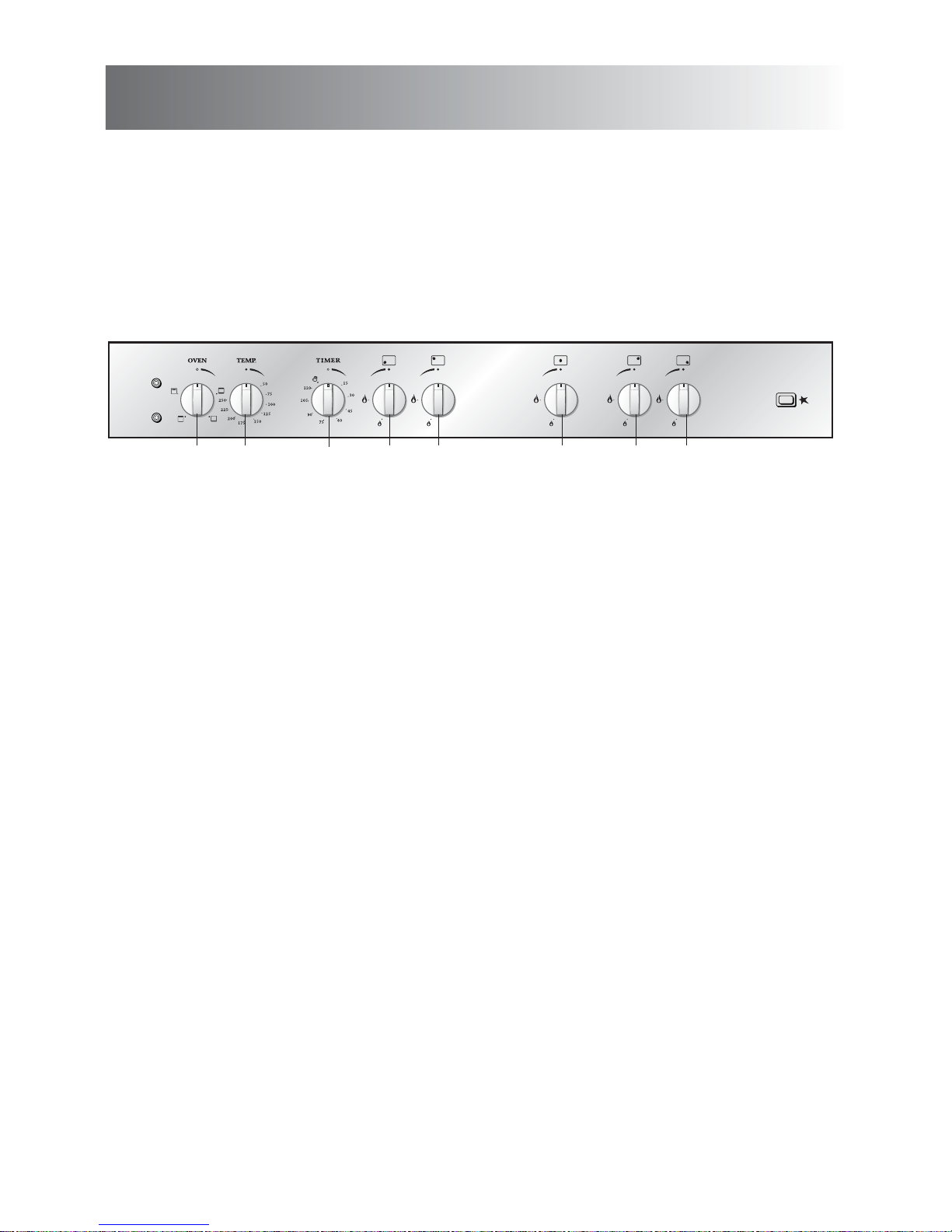
2 - CONTROL PANEL
Fig. 2.1
12 45 6 7 8
9
10
11
3
CONTROL PANEL - Controls description
1. Conventional oven switch knob
2. Conventional oven temperature knob
3. 120’ cut-off timer control knob
4. Front left burner control knob
5. Rear left burner control knob
6. Central burner control knob
7. Rear right burner control knob
8. Front right burner control knob
Pushbutton and pilot lamps:
9. Electronic ignition pushbutton
10. Power on indicator light
11. Oven thermostat indicator light
Page 6
6
3 - USE OF COOKING HOB
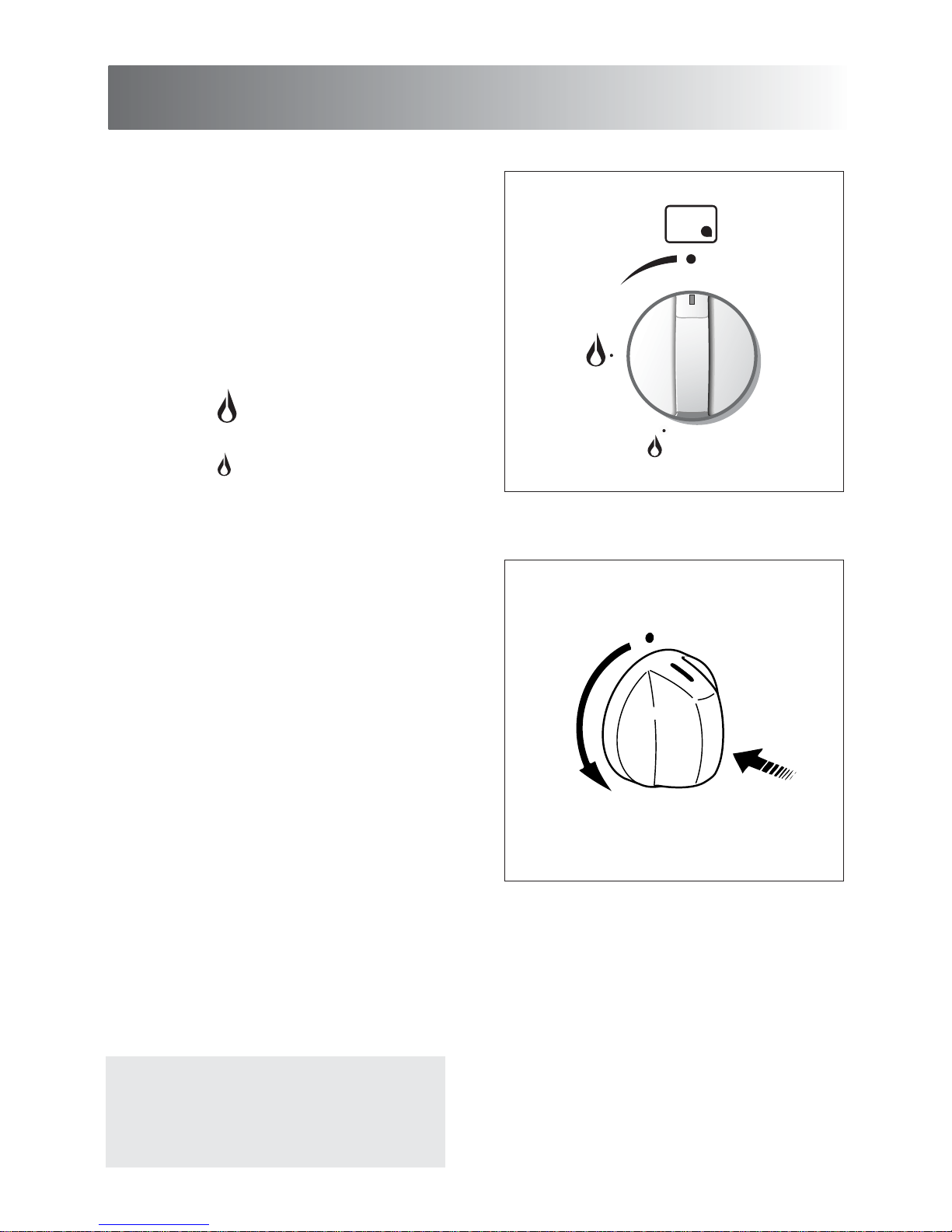
Fig. 3.1
Fig. 3.2
- To reduce the gas flow to minimum,
rotate the knob further anti-clockwise
to the small flame symbol.
- The maximum aperture position per-
mits rapid boiling of liquids, whereas
the minimum aperture position allows
slower warming of food or maintaining
boiling conditions of liquids.
- Other intermediate operating adjust-
ments can be achieved by positioning
the indicator between the maximum
and minimum aperture positions, and
never between the maximum aperture
and closed positions.
GAS BURNERS
Each burner is controlled by a gas tap
assuring the opening and the closing of
the gas supply.
Make the lever of the knob match with
the symbol printed on the control panel
to obtain:
- symbol
● : off
- symbol : full on (nominal rate)
- symbol : reduced rate
Caution!
the cooking hob becomes very hot
during operation.
Keep children well out of reach.
Page 7
7
Fig. 3.4
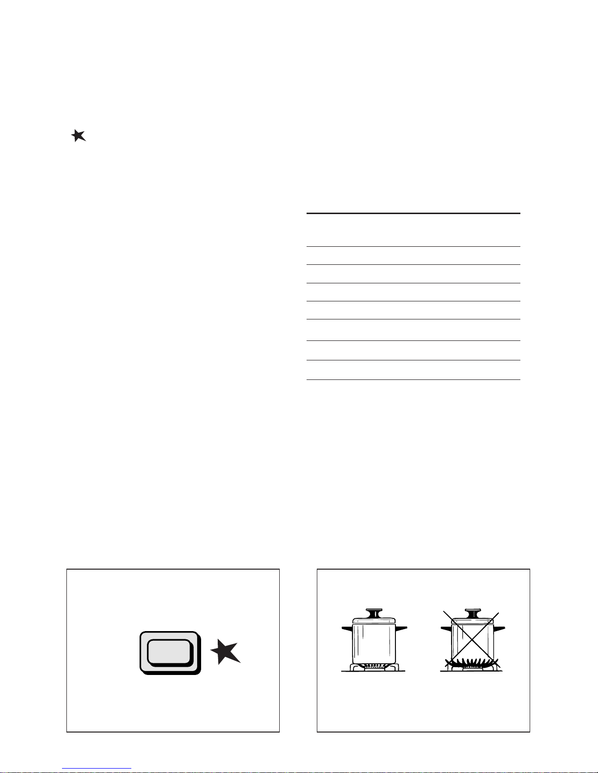
ELECTRIC SPARK IGNITION
To light the burner you have to rotate
the knob (fig. 3.2) corresponding to the
specific burner to the maximum flame
position (large flame symbol) and press
the ignition button marked by the symbol
(fig. 3.3).
The sparks produced by the electrodes
situated next to the burner will light the
selected burner.
If conditions of the local gas supply
makes it difficult to light the gas burner
with the knob set to the high flame position, rotate the knob to the lower flame
position and repeat the ignition.
In the case of a mains failure light the
burner with a match or lighted taper.
N.B. When the cooker is not being used,
set the gas knobs to their closed positions and also close the cock valve on
the gas bottle or the main gas supply
line.
CHOICE OF THE BURNER
On the control panel, near every knob,
there is a diagram that indicates which
burner is controlled by that knob.
The suitable burner must be chosen
according to the diameter and the
capacity used.
As an indication, the burners and the
pots must be used in the following way:
It is important that the diameter of the
pot be suitable to the potentiality of the
burner so as not to compromise the high
output of the burners and therefore
energy waste.
A small pot on a large burner does not
give you a boiling point in a shorten
amount of time since the capacity of
heat absorption of a liquid mass
depends on the volume and the surface
of the pot.
DIAMETERS OF PANS WHICH MAY BE USED
ON THE HOBS
BURNERS MINIMUM MAX.
Auxiliary 12 cm 16 cm
Semirapid 16 cm 22 cm
Rapid 20 cm 24 cm
Double-ring up to 30 cm
Wok max 36 cm
do not use pans with concave or convex bases
Fig. 3.3
Page 8

8
Fig. 3.5bFig. 3.5a
WRONG
CORRECT
SPECIAL GRIDS FOR WOKS (fig. 3.5a - 3.5b)
The special grid for woks rests on the grid of the double-crown burner.
Warning:
– Using woks without this special grid could seriously damage the burner.
– Do not use this grid with flat bottomed pans (Figs.
3.5a - 3.5b).
IMPORTANT:
The special grille for wok pans (fig. 3.5b) MUST BE PLACED ONLY over the pan-rest for
the
double
-ring burner.
Page 9
9
Attention: the oven door becomes
very hot during operation.
Keep children away.
4 -
ELECTRICAL CONVECTION OVEN
GENERAL FEATURES
The convection oven is equipped with 3
electrical heating elements:
– 2 elements (upper and lower) for nor-
mal oven cooking
– 1 grill element, on the top of the oven,
for grilling which must be done with
the oven door closed.
The input of the elements is:
– Upper element, 1725 W
– Lower element, 1725 W
– Grill element, 2500 W
Fig. 4.1
Fig. 4.2
NOTE:
Upon first use, it is advisable to operate
the oven at the maximum temperature
(thermostat knob on position 250°C) for
60 minutes in the position and for
another 15 minutes in the mode in
order to eliminate any traces of grease
from the electrical resistances.
WARNING:
The door is hot use the handle.
OPERATING PRINCIPLES
Heating and cooking in the CONVENTIONAL oven are obtained in the following ways:
a. by normal convection
The heat is produced by the upper and
lower heating elements.
b. by radiation
The heat is radiated by the infra red
grill element (use with the oven door
closed.).
Page 10
10
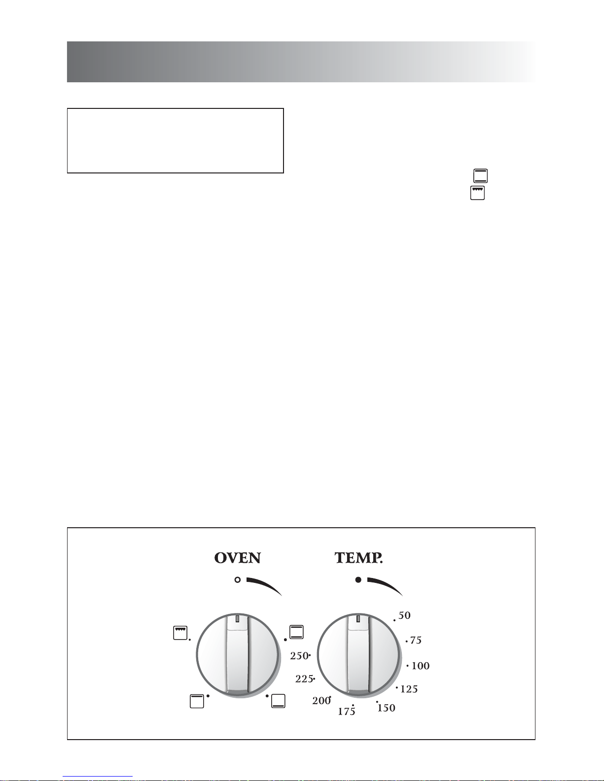
FUNCTION SELECTOR KNOB (Fig. 4.1)
Rotate the knob clockwise to set the
oven for one of the following functions.
TRADITIONAL CONVECTION
COOKING
The upper and lower heating elements are
switched on. The heat is diffused by natural convection and the temperature must be
regulated between 50° C and 250°C position with the thermostat knob.
It is necessary to preheat the oven before
introducing the foods to be cooked.
Recommended for:
For foods which require the same
cooking temperature both internally and
externally, i. e. roasts, spare ribs,
meringue, etc.
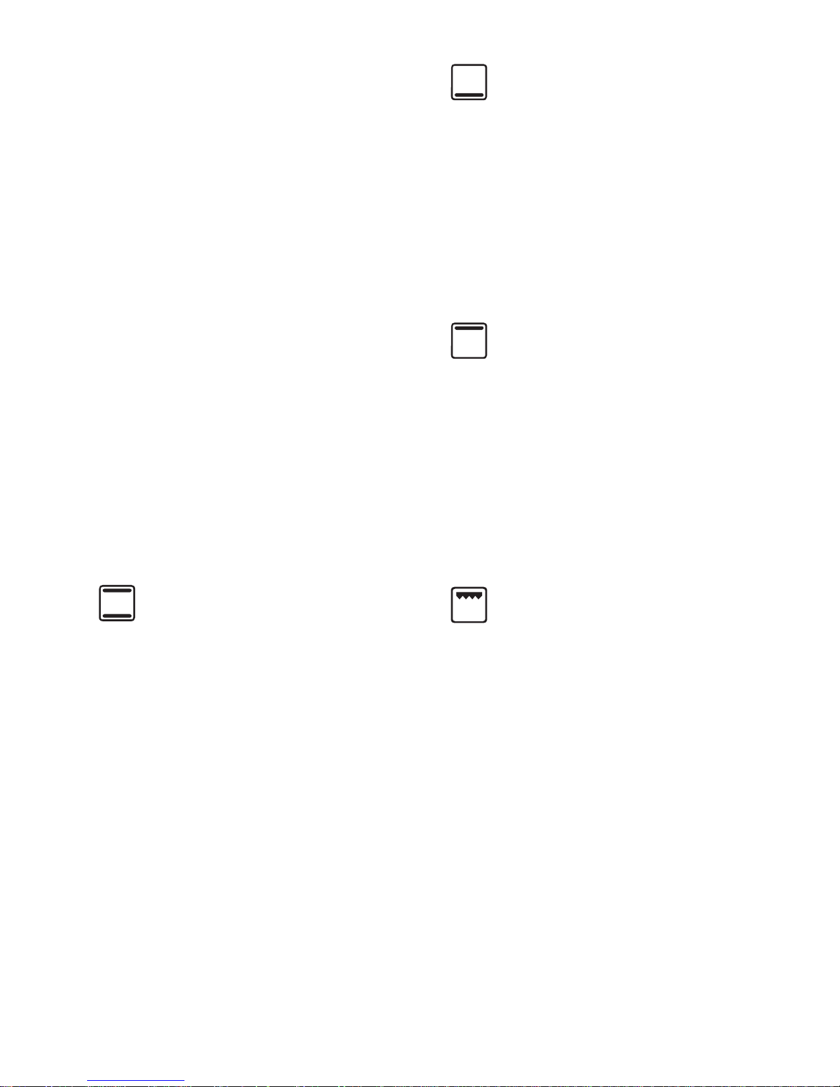
LOWER HEATING ELEMENT
In this position only the lower element is
switched on. Heat is distributed by natural convection. The thermostat can be
set between 50 and 150°C; higher temperatures are not available.
Recommended for:
This mode is particularly suitable to
complete cooking of dishes that require
higher temperature at the bottom.
UPPER HEATING ELEMENT
In this position only the upper element is
switched on. Heat is distributed by natural convection. The thermostat can be
set between 50 and 150°C; higher temperatures are not available.
Recommended for:
This mode is particularly suitable to
complete cooking of dishes that require
higher temperature at the top.
THERMOSTAT KNOB
(Fig. 4.2)
This only sets the cooking temperature
and does not switch the oven on.
Rotate clockwise until the required
temperature is reached (from 50 to 250°
C).
The temperature indicator light signals
when the heating elements are switched
on or switched off.
OVEN LIGHT
The oven is equipped with a light that
illuminates the oven to enable visually
controlling the food that is cooking.
This light is controlled by the selector
knob (fig. 4.1)
It remains on in all the cooking modes.
GRILLING
The infra-red heating element is switched
on. The heat is diffused by radiation.
Use with the oven door closed and the
thermostat knob to between 50°C and
200°C.
For correct use see chapter “USE OF THE
GRILL”
Before using the grill, preheat for about
five minutes.
Always grill with the oven door closed
and do not use the grill for longer than
30 minutes at any one time.
Caution: The oven door becomes very
hot during operation.
Keep children well out of reach.
Recommended for:
Intense grilling action for cooking with a
broiler; browning, crisping, “au gratin”,
toasting, etc.
Page 11

11
USE OF THE GRILL
Leave to warm up for approximately 5
minutes with the door closed.
Place the food inside positioning the rack
as near as possible to the grill.
Insert the drip pan under the rack to collect the cooking juices.
Grilling with the oven door closed.
Grilling with the oven door closed and
do not for longer than 30 minutes at
any one time.
Attention: the oven door becomes
very hot during operation.
Keep children away.
OVEN COOKING
Before introducing the food, preheat the
oven to the desired temperature.
For a correct preheating operation, it is
advisable to remove the tray from the
oven and introduce it together with the
food, when the oven has reached the
desired temperature.
Check the cooking time and turn off the
oven 5 minutes before the theoretical
time to recuperate the stored heat.
COOKING EXAMPLES
Temperatures and times are
approximate as they vary depending on
the quality and amount of food.
Remember to use ovenproof dishes and
to adjust the oven temperature during
cooking if necessary.
DISHES TEMPERATURE
Lasagne 190°
Baked pasta 190°
Pizza 220°
Creole rice 190°
Baked onions 190°
Spinach crêpes 185°
Potatoes baked in milk 185°
Stuffed tomatoes 180°
Cheese soufflé 170°
Roast veal 180°
Grilled veal chops 210°
Chicken breasts with tomato 180°
Grilled chicken - roast chicken 190°
Veal loaf 175°
Roast beef 170°
Fillet of sole 175°
Aromatic hake 170°
Beignets 160°
Ring cake 150°
Plum tart 170°
Jam tartlets 160°
Sponge cake 170°
Sweet dough 160°
Sweet puffs 170°
Plain sponge cake 170°
SAFETY GUARD
The glass on the oven door reaches
high temperatures during operation.
For child safety, a door guard can be
fitted to prevent contact with the hot
glass.
The door guard is supplied as an
accessory at extra cost on request.
Contact one of our dealers or Service
Centre and indicate the relevant appliance model.
Page 12

12
5 - 120’ CUT-OFF TIMER
Fig. 5.1
TIMER (Fig. 5.1)
The timer runs the electric oven for a
preset time.
1) Starting up.
After setting the electric oven selector
knob rotate the timer knob clockwise
until you reach the required cooking
time (max 120 minutes).
Once this time has elapsed, the timer
will return to the “0” position and the
electric oven will automatically switch
off.
2) Manual position.
If you wish to use the oven manually,
switching it off as required, the timer
knob must be turned to position .
Page 13

13
6 - CLEANING AND MAINTENANCE
IMPORTANT NOTES
Installation, and any demonstration, information or adjustments are not included in
the warranty.
The cooker must be installed by a qualified person in accordance with the Gas
Safety (Installation and Use) (Amendment) Regulations 1990 and the relevant
building/l.E.E Regulations.
Failure to install the appliance correctly could invalidate any manufacturers warranty
and lead to prosecution under the above quoted regulation.
In the UK C.O.R.G.I registered installers are authorised to undertake the installation
and service work in compliance with the above regulations. All Curry’s authorised
installers are C.O.R.G.I. registered.
Attention
The appliance gets very hot, mainly
around the cooking areas. It is very
important that children are not left
alone in the kitchen when you are
cooking.
Do not use a steam cleaner
because the moisture can get into
the appliance thus make it unsafe.
Page 14

14
Fig. 6.1
BURNERS
They can be removed and washed with
soapy water only.
They will remain always perfect if cleaned
with products used for silverware.
After cleaning or washing, check that
burner-caps and burner-heads are dry
before placing them in the respective
housings.
Special attention has to be paid in
order not to exchange the housing of
the small burners shown in fig. 6.1.
It is absolutely necessary to check the
perfect housing of the burner-ring as an
incorrect housing may cause serious
problems.
Check also that the electrodes for
ignition are always clean in order to
ensure a regular spark.
N.B. To avoid damage to the electric
ignition, do not use it when the burners
are not in place.
Burner-cap ring
partially drilled
Burner-cap rings
fully drilled
ENAMELLED PARTS
All the enamelled parts must be cleaned
with a sponge and soapy water or other
non-abrasive products.
Dry preferably with a soft cloth.
Acidic substances like lemon juice,
tomato sauce, vinegar etc. can damage
the enamel if left too long.
STAINLESS STEEL SURFACES
(COATED)
The stainless steel front panels on this
cooker (facia, oven door, bottom panel)
are protected by a finger-print proof lacquer.
To avoid damaging this lacquer, do not
clean the stainless steel with abrasive
cleaners or abrasive cloths or scouring
pads.
ONLY SOAPY/WARM WATER MUST
BE USED TO CLEAN THE (COATED)
STAINLESS STEEL SURFACES.
STAINLESS STEEL SURFACES
(UNCOATED)
The hob + sides are made from uncoated stainless steel.
Can be cleaned with an appropriate
stainless steel cleaner.
WARNING
When correctly installed, your product
meets all safety requirements laid down
for this type of product category.
However special care should be taken
around the rear or the underneath of
the appliance as these areas are not
designed or intended to be touched and
may contain sharp or rough edges, that
may cause injury.
Page 15

15
REPLACING THE OVEN LIGHT BULB
Switch the cooker off at the mains.
When the oven is cool unscrew and
replace the bulb with another one
resistant to high temperatures (300°C),
voltage 230 V (50 Hz), 15 W, E14.
Note: Oven bulb replacement is not
covered by your guarantee.
INSIDE OF OVEN
This must be cleaned after every use.
Remove and refit the side runner frames
as described on the next chapter.
With the oven warm, wipe the inside
walls with a cloth soaked in very hot
soapy water or another suitable product.
The bottom of the oven, side runner
frames, tray and rack can be removed
and washed.
FLEXIBLE TUBE
From time to time, check the flexible
tube connecting the gas supply to the
cooker.
It must be always in perfect condition;
in case of damage arrange for it to be
replaced by a C.O.R.G.I. registered
installer.
GAS TAPS
In the event of operating faults in the
gas taps, call the Service Department.
Fig. 6.2
Fig. 6.3
ASSEMBLY AND DISMANTLING OF
THE SIDE RUNNER FRAMES
– Fit the side runner frames into the
holes on the side walls inside the
oven (Fig. 6.2)
– Slide the tray and rack into the runners
fig. 6.3.
The rack must be fitted so that the
safety catch, which stops it sliding out,
faces the inside of the oven (fig. 6.4).
– To dismantle, operate in reverse
order.
Page 16

16
Fig. 6.5
L
F
OVEN FLOOR
The oven floor “F” (fig. 6.5) can be easily
removed to facilitate cleaning.
Remember to replace the floor correctly
afterwards.
Be careful not to confuse the tray “L”
with the oven floor “F”.
Fig. 6.4
OVEN DOOR
The internal glass panel can be easily
removed for cleaning by unscrewing the
4 retaining screws (Fig. 6.4)
Do not store flammable material in
the oven
OVEN TRAY
The oven tray must be insert into the
side runners (fig. 6.5).
Page 17

17
The oven door can easily be removed as
follows:
– Open the door to the full extent (fig.
6.6A).
– Attach the retaining rings to the hooks
on the left and right hinges (fig. 6.6B).
– Hold the door as shown in fig. 6.6.
– Gently close the door and withdraw the
lower hinge pins from their location
(fig. 6.6C).
– Withdraw the upper hinge pins from
their location (fig. 6.6D).
– Rest the door on a soft surface.
– To replace the door, repeat the above
steps in reverse order.
Fig. 6.6D
Fig. 6.6C
Fig. 6.6B
Fig. 6.6A
REMOVING THE OVEN DOOR
Fig. 6.6
Page 18

18
IMPORTANT
– Cooker installation, regulation and conversion to other gas types must only be carried
out by QUALIFIED TECHNICIANS. Failure to observe this rule will invalidate the warranty.
– The electrical mains outlet, if located behind the cooker, must not be higher than 18 cm
above the floor level.
– Some appliances are supplied with a protective film on steel and aluminium parts.
This film must be removed before using the cooker.
Advice for the installer
880 ÷ 905
600
900
USABLE lit = 112
Fig. 7.0
Page 19

19
Fig. 7.1
7 - INSTALLATION
This cooker has type X overheating protection so that it can be installed next to a
cabinet.
If the cooker is installed adjacent to furniture which is higher than the gas hob cooktop, a
gap of at least 200 mm must be left between the side of the cooker and the furniture.
The furniture walls adjacent to the cooker must be made of material resistant to heat.
The veneered syntetical material and the glue used must be resistant to a temperature of
90°C in order to avoid ungluing or deformations.
The cooker may be located in a kitchen, a kitchen/diner or bed-sitting room but not in a
room containing a bath or shower.
Curtains must not be fitted immediatly behind appliance or within 500 mm of the sides.
It is essential that the cooker is positioned as stated below.
The cooker must be installed by a qualified technician and in compliance with
local safety standards.
650 mm
500 mm
450 mm
200 mm
Page 20

20
FITTING THE ADJUSTABLE FEET
The adjustable feet must be fitted to the base of the cooker before use.
Rest the rear of the cooker an a piece of the polystyrene packaging exposing the base
for the fitting of the feet.
Fig. 7.2
Fig. 7.3
ASSEMBLING THE
BACKGUARD
• Remove the two spacers “A”
and the screw “B” from the
rear of the cooktop.
• Assemble the backguard as
shown in figure 7.4 and fix it
by screwing the central
screw “B” and the spacers
“A”.
B
A
A
Fig. 7.4
LEVELLING THE COOKER
The cooker may be levelled by
screwing the lower ends of the
feet IN or OUT (fig. 7.3).
Page 21

21
Fig. 7.5
Fig. 7.6
Fig. 7.7
WARNING
When raising cooker to upright position always ensure two people carry
out this manoeuvre to prevent damage to the adjustable feet (fig. 7.5).
WARNING
Be carefull: do not lift the cooker by
the door handle when raising to the
upright position (fig. 7.6).
WARNING
When moving cooker to its final position
DO
NOT DRAG (fig. 7.7).
Lift feet clear of floor (fig. 7.5).
MOVING THE COOKER
Page 22

22
PROVISION FOR VENTILATION
The room containing the cooker should have an air supply in accordance with BS.5540:
Part 2: 1989.
All rooms require an openable window or equivalent while some rooms require a
permanent vent in addition to the openable window.
The cooker should not be installed in a bed-sitting room, of volume less than 21 m
3
.
Where a DOMESTIC COOKER is installed in a room or internal space, that room or
internal space shall be provided with a permanent opening which communicates directly
with outside air and is sized in accordance with table below. In domestic premises the
permanent opening shall be an air vent.
If there are other fuel burning appliances in the same room, BS.5540: Part 2: 1989 should
be consulted to determine the requisite air vent requirements.
If the cooker is installed in a cellar or basement, it is advisable to provide an air vent of
effective area 100 cm
2
, irrespective of the room volume.
(❊)
If the room or internal space containing these appliances has a door which
opens directly to outside, no permanent opening is required.
MINIMUM PERMANENT OPENING FREE AREA FOR FLUELESS APPLIANCE
5 m3to 10
m
3
Openable
window or
equivalent also
required
Maximum
appliance
rated input
limit
Room volume
11 m3to
20 m
3
> 20 m
3
< 5 m
3
Type of appliance
Domestic oven,
hotplate, grill or any
combination thereof.
None
50 (❊)
cm
2
Nil
cm
2
Nil
cm
2
100
cm
2
Yes
Page 23

23
8 - GAS SECTION
GAS INSTALLATION
IMPORTANT NOTE
This appliance is supplied for use on
NATURAL GAS only and cannot be
used on any other gas without modification.
This appliance is manufactured for
conversion to LPG if required.
If the injectors are not supplied they can
be obtained from the After-Sales
Service.
The cooker must be installed by a qualified person in accordance with the Gas
Safety (Installation and Use)
(Amendment) Regulation 1990 and the
relevant building/l.E.E. Regulations.
The following British Standards should
be used as reference when installing
this appliance.
BS6172 1990, BS5440 part 2 1989 and
BS6891 1988.
Failure to install the appliance correctly
could invalidate any manufacturers warranty and lead to prosecution under the
above quoted regulation.
In the UK C.O.R.G.I registered installers
are authorised to undertake the installation and service work in compliance with
the above regulations.
GAS CONNECTION
The installation of the cooker to Natural
Gas or LP Gas must be carried out by a
qualified gas engineer. Installers shall
take due account of the provisions of the
relevant British Standards Code of
Practice, the Gas Safety Regulations
and the Building Standards (Scotland)
(Consolidation) Regulations issued by
the Scottish Development Department.
INSTALLATION TO NATURAL GAS
Installation to Natural Gas must conform
to the Code of Practice, etc. The supply
pressure for Natural Gas is 20 mbar.
INSTALLATION TO LP GAS
This appliance must only be connected
to LPG after an LPG conversion kit has
been fitted, (see pages from 26 to 28).
When operating on Butane gas a supply
pressure of 28-30 mbar is required.
When using Propane gas a supply pressure of 37 mbar is required.
The installation must conform to the relevant British Standards.
Warning: Only a qualified gas engineer,
also with technical knowledge of electricity should install the cooker. He
should observe the Regulations and
Codes of Practice governing such installation of gas cookers.
Note: It is recommended that the gas
connection to the cooker is installed with
a flexible connecting tube made to BS
5386.
Page 24

24
1/2” BSP (male)
Left gas
inlet pipe
Right gas
inlet pipe
Plug
Fig. 8.1
GAS CONNECTION
The gas supply must use the nearest gas inlet pipe which is located at the left or the
right hand side at the rear of the appliance (fig. 8.1). The unused end inlet pipe must
be closed with the plug interposing the gasket.
Flexible hoses can be used where the sited ambient temperature of the hose does not
exceed 70°C. These hoses must be manufactured in accordance with BS669 part 1
and be of the correct construction for the type of gas being used.
The hose should not be crushed or trapped or be in contact with sharp or abrasive
edges. It should also not be subjected to corrosion by acidic cleansing agents.
The hose should also be connected in such away that it does not touch the floor.
NB: Gas hoses designed for natural gas MUST NOT be used for supplying LPG gas
(LPG gas hoses can be identified by a either a red band or stripe on the rubber outer
coating of the hose).
Page 25

25
Fig. 8.2
IMPORTANT PRESCRIPTIONS FOR GAS CONNECTION
700 mm
Rear wall
Suggested area for
gas mains connection
200 mm
Fig. 8.3
To avoid damage to the appliance gas
rail inlet pipe the fittings should be
tightened using two suitable spanners
(fig. 8.2).
After connection to the mains gas
supply the couplings should be
checked for gas soundness/tightness
as per current regulations for the gas
type being used.
Page 26

26
CONVERSION TO LPG
1 - Injectors replacement of top burners
The injectors can be obtained from the “Service Centre”.
To replace the injectors it is necessary to lift the hobtop and proceed as follows:
– Remove pan-supports and burners from the hobtop.
– Remove the backguard “E” by unscrew the central screw “B” and the two side screws
“A” (fig. 8.4a).
– Unscrew the 4 screws “C” and the central screw “D” (figs. 8.4b - 8.4c).
– Pull forwards the hobtop to release it, then lift following arrow “F” (fig. 8.4c)
– Hold the hobtop open by a support.
– Fully raise the adjusting air tube “K” (fig. 8.5) in order to easily reach the injector.
– By an angle 7 spanner, remove the injector from its housing and replace it by the prop-
er one according to the kind of gas (see following tables - page 28).
Each injector can be identified by the engraving of the hole diameter expressed in hun-
dredths of a millimetre.
C
C
D
F
F
Fig. 8.4c
B
A
E
Fig. 8.4a
Fig. 8.4b
D
C
C
C
C
Page 27

27
2 - Adjusting of primary air
of the top burners
By releasing the screw “M”, reset the air
adjuster “K” according to the instructions
see “Table for the choice of the
injectors”, where the distance between
injector and air adjuster is recommended
(in mm).
Before lowering the hob top, set the
burners on their sites and light them in
order to check whether the flames are
correct, as per the specifications given in
the next page. In case of incorrect flame,
lift or lower the air adjuster.
Fig. 8.5
M
J
K
3 - Adjusting of the minimum
of the top burners
In the minimum position the flame must
have a length of about 4 mm and must
remain lit even with a quick turn from the
maximum position to that of minimum.
The flame adjustment is done in the
following way:
– Turn on the burner
– Turn the tap to the MINIMUM position
– Take off the knob
– With a small flat screwdriver turn the
screw inside the tap rod to the correct
regulation (fig. 8.6).
Normally for LPG, tighten up the
regulation screw.
Fig. 8.6
Flame Flame Flame
faulty in correct with excess
primary air primary air
long, yellow clear short and sharp
and interior blue too blue interior
trembling cone cone tending to
detach
CAUSE
air regulating correct air regulating
tube, too distance of tube, too
closed the tube open
Flame correct
Flame faulty in
primary air
Flame with excess
primary air
Page 28

28
LUBRICATION OF THE GAS TAPS
The operations must be executed by a qualified technician.
IMPORTANT
All intervention regarding installation maintenance and conversion of the appliance must be fulfilled with original factory parts.
The manufacturer declines any liability resulting from the non-compliance of this
obligation.
TABLE FOR THE CHOICE OF THE INJECTORS
Cat: II 2H3+
GB
INCREASE OF AIR NECESSARY FOR GAS COMBUSTION (2 m
3
/h x kW)
BURNERS Air necessary for combustion [m
3
/h]
Auxiliary (A) 2,00
Semi-rapid (SR) 3,80
Rapid (R) 6,30
Double-ring 6,90
G 30 - 28-30 mbar G 20
BURNERS G 31 - 37 mbar 20 mbar
Auxiliary (A) 1,00 0,30 50 3 * 72 1 *
Semi-rapid (SR) 1,90 0,38 67 5,7 * 100 2 *
Rapid (R) 3,15 0,60 86
fully open
* 130 5 *
Double-ring 3,45 0,85 92
fully open
* 135 5 *
Nominal
Power
[kW]
Reduced
Power
[kW]
Ring opening
[mm]
Ø injector
[1/100 mm]
Ring opening
[mm]
Ø injector
[1/100 mm]
*
= Reference value
Page 29

29
9 - ELECTRICAL SECTION
N.B. For connection to the mains, do
not use adapters, reducers or
branching devices as they can cause
overheating and burning.
If the installation requires alterations to
the domestic electrical system or if the
socket and appliance plug are
incompatible, call an expert.
He should also check that the socket
cable section is suitable for the power
absorbed by the appliance.
GENERAL
– Connection to the mains must be car-
ried out by qualified personnel in
accordance with current regulations.
– The appliance must be connected to
the mains checking that the voltage
corresponds to the value given in the
rating plate and that the electrical
cable sections can withstand the load
specified on the plate.
– The appliance can be connected
directly to the mains placing an
omnipolar switch with minimum opening between the contacts of 3 mm
between the appliance and the mains.
– The power supply cable must not
touch the hot parts and must be positioned so that it does not exceed 75°C
at any point.
– Once the appliance has been
installed, the switch or socket must
always be accessible.
IMPORTANT: The cooker must be
installed in accordance with the
manufacturer’s instructions.
Incorrect installation, for which the
manufacturer accepts no responsi-
bility, may cause injury to persons
or animals etc.
Before effecting any intervention
on the electrical parts of the appliance, the connection to the network must be interrupted.
The connection of the appliance
to earth is mandatory.
The manufacturer declines all
responsibility for any inconvenience resulting from not
observing this condition.
IMPORTANT: this cooker must be
connected to a suitable double
pole control unit adjacent to the
cooker.
NO DIVERSITY CAN BE APPLIED
TO THIS CONTROL UNIT.
IMPORTANT:
This appliance must be earthed.
Page 30

30
FEEDER CABLE SECTION
TYPE H05RR-F
230 V 3 x 1,5 mm
2
ELECTRICAL FEEDER CABLE
CONNECTION
To connect the supply cable:
- Remove the screws securing the
cover “A” on the rear of the cooker
(fig. 9.1).
- Feed the supply cable through the
cable clamp “D”. The supply cable
must be of a suitable size for the cur-
rent requirements of the appliance;
see the section “Feeder cable section”
(fig. 9.1).
- Connect the wires to the terminal
block “B” as shown in the diagram in
figure 9.2; or connect the phase wires
to the terminal block “B” and the earth
wire to the terminal PE as shown in
figure 9.1.
- Take up any slack in the cable and
secure with the cable clamp “D”.
- Replace the cover “A”.
N.B. The earth conductor must be left
about 3 cm longer than the others.
Fig. 9.1
D
B
PE
A
N
L
230 V
PEN
L
1
(L2)
Fig. 9.2
PE Earth
N Neutral
L Live
Page 31

31
AFTER SALES SERVICE
If you require After Sales Service contact the MASTERCARE Domestic Appliance Helpline
Telephone 08701 565550.
Ser. Nr.
The manufacturer cannot be held responsible for possible inaccuracies due to printing or transcription errors in the present booklet.
The manufacturer reserves the right to make all modifications to its products deemed necessary for
manufacture or commercial reasons at any moment and without prior notice, without jeopardising the
essential functional and safety characteristics of the appliances.
IMPORTANT INFORMATION FOR CORRECT DISPOSAL OF THE PRODUCT IN
ACCORDANCE WITH EC DIRECTIVE 2002/96/EC.
At the end of its working life, the product must not be disposed of as urban waste. It must
be taken to a special local authority differentiated waste collection centre or to a dealer
providing this service.
Disposing of a household appliance separately avoids possible negative
consequences for the environment and health deriving from inappropriate disposal and enables the constituent materials to be recovered to
obtain significant savings in energy and resources. As a reminder of the
need to dispose of household appliances separately, the product is
marked with a crossed-out wheeled dustbin.
Page 32

Cod. 1102463 - ß5
 Loading...