

Elba E30-021, E30-020, AS E30-020, E30-040, AS E30-040 Instructions For The Use - Installation Advices
...Page 1
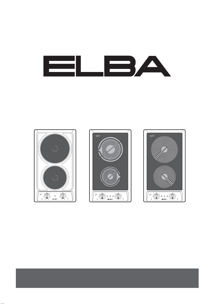
E30-021
SCHOTT
E30-020
AS
E30-020 E30-040 E30-050
Cod. 1103482 - ß
Instructions for the use - Installation advices
AS
E30-040
E30-050
AS
Page 2

2
INTRODUCTION
BEFORE USING THE COOKTOP
1. Clean the cooktop.
2. Switch on the hotplates to remove fumes and smells coming from the protective
greases.
EVERYDAY USE
1. Turn the control knob to the position required.
2. To switch off, turn the knob back to “0”.
Please read the instructions for use carefully, to become familiar with your cooktop.
Page 3
3
2
1
3
5
4
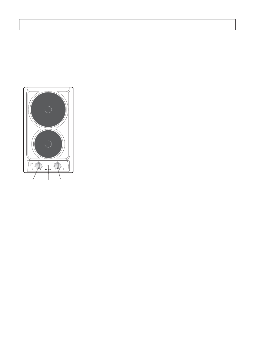
FEATURES
“
2 ELECTRIC” HOTPLATE COOKTOP
- Electrical insulation Class I.
- Protection against overheating of adjacent
surfaces Type Y.
ELECTRIC HOTPLATES
CONTROL PANEL DESCRIPTION
3. Electrical plate 1 control knob
4. Electrical plate 2 control knob
5. Power indicator light
E30-021
E30-020
AS E30-020
1. Electrical plate Ø 145 - normal (1000 W)
2.
Electrical plate
E30-021 - normal (1500 W)
E30-020, AS E30-020 - rapid (red dot) (2000 W)
Ø 180
Page 4
4
3
5 7 6
4
2
1
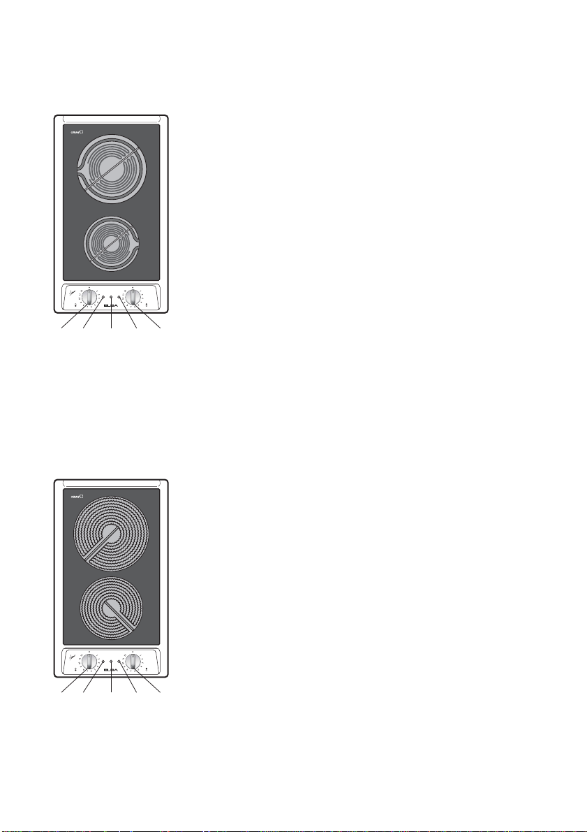
GLASS CERAMIC COOKTOP
- Electrical insulation Class I.
- Protection against overheating of adjacent
surfaces Type Y.
COOKING ZONES
1. Halogen cooking zone Ø 145 - 1200 W
2. Halogen cooking zone Ø 180 - 1800 W
CONTROL PANEL DESCRIPTION
3. Front zone control knob (1)
4. Rear zone control knob (2)
5. Front zone residual heat indicator (1)
6. Rear zone residual heat indicator (2)
7. Cooking zone ON indicator light
3
5 7 6
4
2
1
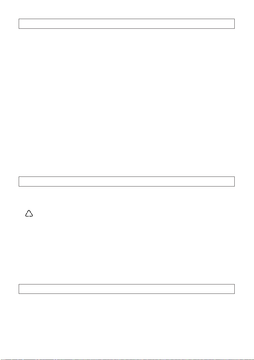
GLASS CERAMIC COOKTOP
- Electrical insulation Class I.
- Protection against overheating of adjacent
surfaces Type Y.
COOKING ZONES
1. Hi-light cooking zone Ø 145 - 1200 W
2. Hi-light cooking zone Ø 180 - 1800 W
CONTROL PANEL DESCRIPTION
3. Front zone control knob (1)
4. Rear zone control knob (2)
5. Front zone residual heat indicator (1)
6. Rear zone residual heat indicator (2)
7. Cooking zone ON indicator light
E30-040
AS E30-040
SCHOTT
E30-050
AS E30-050
Page 5
5
BEFORE USING THE COOKTOP
● For best use of your cooktop, read the instructions for use carefully and keep
them in a safe place.
● This appliance must only be used for the purpose for which it was designed, i.e.
for cooking foods.
Any other use should be considered incorrect and therefore dangerous.
● The manufacturer declines all responsibility for damage caused by unreason-
able, incorrect or rash use of the appliance.
● Do not try to alter the technical features of the appliance, because this could be
very dangerous.
● Packaging materials (plastic bags, polystyrene pieces, etc...) must be stored out of
the reach of children as they are potentially dangerous.
● Check that the cooktop has not been damaged during transport. If in doubt, consult a
specialised engineer.
● Make sure that the installation and electrical connections are made by a quali-
fied electrician following the manufacturer's instructions and in compliance with
local regulations in force.
TIPS FOR SAFEGUARDING THE ENVIRONMENT
1. Packaging
The packaging material is 100% recyclable and is marked with the recycling symbol
to identify the type of material which must be taken to the local collection centres.
2. Product
The cooktop has been manufactured with recyclable material. Dispose of it following
the local regulations for the disposal of waste.
Before disposing of it make it unusable by cutting off the supply cable.
TROUBLE-SHOOTING GUIDE
The electric hotplates or the cooking zones do not heat up.
Check whether:
● the corresponding regulating knob has been turned to the correct power?
● there is a power cut?
Page 6
6
WARNINGS FOR THE USE OF ELECTRICAL APPLIANCES
When using electrical appliances some important rules must always be followed.
In particular:
● Never touch the appliance with wet or damp hands or feet.
● Never use the appliance with bare feet.
● Keep children away from the hob when it is in use.
● Before any cleaning or maintenance, switch off the electricity to the cooktop.
● Risk of fire!
● Do not leave inflammable material on
the cooktop.
● Make sure that the electrical cables
of other appliances installed nearby
cannot come into contact with the
cooktop.
● Keep children away from the appli-
ance, especially when it is being
used.
● During and immediately after use
some parts of the cooktop reach very
high temperatures.
Do not touch them.
● Never cook the food directly on the
electric hotplates or on the glass
ceramic cooktop, but in special pans
or containers.
If the cooktop is fitted with a
glass cover:
● Do not close the glass cover when
the electric hotplates are still hot. If
there is an oven under the cooktop,
do not close the cover when the oven
is switched on or still hot.
● Do not put pans or heavy objects on
the cover.
● Dry off any liquid which may have
spilt on the cover before opening it.
EC Declaration of conformity CE
● This cooktop is intended to come into
contact with food products and conforms with European Directive
89/109/EEC.
● This cooktop has been designed for
use only as a cooking appliance. Any
other use (e.g. heating rooms) should
be considered incorrect and therefore
dangerous.
● This cooktop has been designed,
constructed and put on to the market
in conformity with:
- Safety requirements of the “Low
Voltage” Directive 2006/95 and
amendments;
- Protection requirements of the
“EMC” Directive 89/336/EEC and
amendments;
- Requirements of Directive
93/68/EEC.
PRECAUTIONS AND GENERAL SUGGESTIONS
Page 7
7
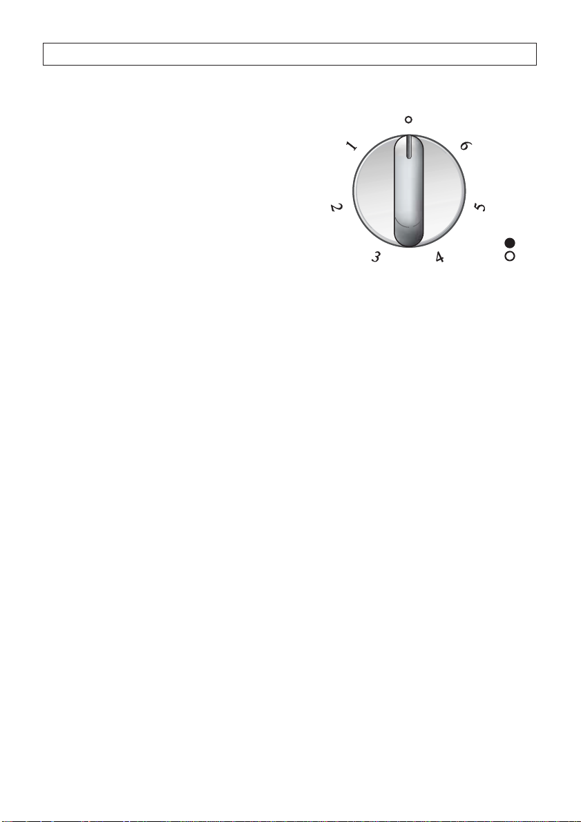
Switch on the electric hotplates by turning the knob to the position required.
Once the food is boiling turn down the
power according to the heating intensity
required. The hotplate will continue to
give out heat for 5 minutes after it has
been switched off.
The features of these electric hotplates,
which are fitted with a heating limiter,
allow:
– rapid reaching of the temperature
– maximum use of the power with flat-
bottomed
– limitation of the power if the pan is
unsuitable.
The hotplate temperature is adjusted by
a 7-position changeover switch.
The numbers from 1 to 6 indicate the
operating positions with temperature
increasing with the number.
2 ELECTRIC HOTPLATE COOKTOP
Page 8
8
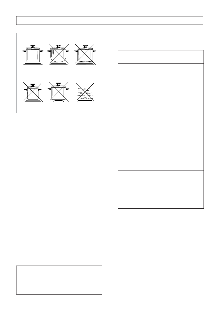
TABLE FOR USE OF THE
COOKING ZONES
Type of cooking
For melting (butter, chocolate).
To keep food warm and to
heat small quantities of liquids.
To heat larger quantities,
whip creams and sauces.
Slow boiling, e.g.: boiled vegetables, spaghetti, soups,
continuing steam cooking of
roasts, stews.
For all types of fried foods,
chops, steaks, cooking without lid, e.g. risotto.
Browning meats, roast potatoes, fried fish and to boil
large quantities of water.
Quick frying, steaks in steak
pan, etc.
Position
of switch
1
2
3
2
3
4
4
4
5
6
2 ELECTRIC HOTPLATE COOKTOP
CORRECT USE OF THE
ELECTRIC HOTPLATES
When using the electric hotplate:
– absolutely avoid idle operation (with-
out pans)
– try not to spill liquids on the hotplates
when they are hot
– only use pans with flat bottoms (elec-
tric type)
– to save electricity use lids when pos-
sible
– always use pans which cover the hot-
plate surface completely.
Operation of the electric hotplates is
signalled by an indicator light.
ATTENTION
During and after use of the electric
hotplates the cooktop becomes hot.
Keep children away.
Page 9
9
GLASS CERAMIC COOKTOP
The cooktop’s glass ceramic surface
allows rapid vertical heat transmission
from the heating elements under the
cooktop to the pans on it.
The heat does not propagate horizontally and thus the cooktop remains “cold”
just a few centimetres away from the
cooking zone.
The two cooking zones are indicated by
two circles drawn on the glass ceramic
surface.
Before switching on the cooktop make
sure that it is clean.
ATTENTION
During and after use of the electric
hotplates the cooktop becomes hot.
Keep children away.
TABLE FOR USE OF THE
COOKING ZONES
Type of cooking
For melting (butter, chocolate).
To keep food warm and to
heat small quantities of liquids.
To heat larger quantities, whip
creams and sauces.
Slow boiling, e.g.: boiled vegetables, spaghetti, soups, continuing steam cooking of
roasts, stews.
For all types of fried foods,
chops, steaks, cooking without
lid, e.g. risotto.
Browning meats, roast potatoes, fried fish and to boil large
quantities of water.
Quick frying, steaks in steak
pan, etc.
Position
of switch
1
2
4
5
6
2
3
4
6
7
7
8
8
9
10
11
12
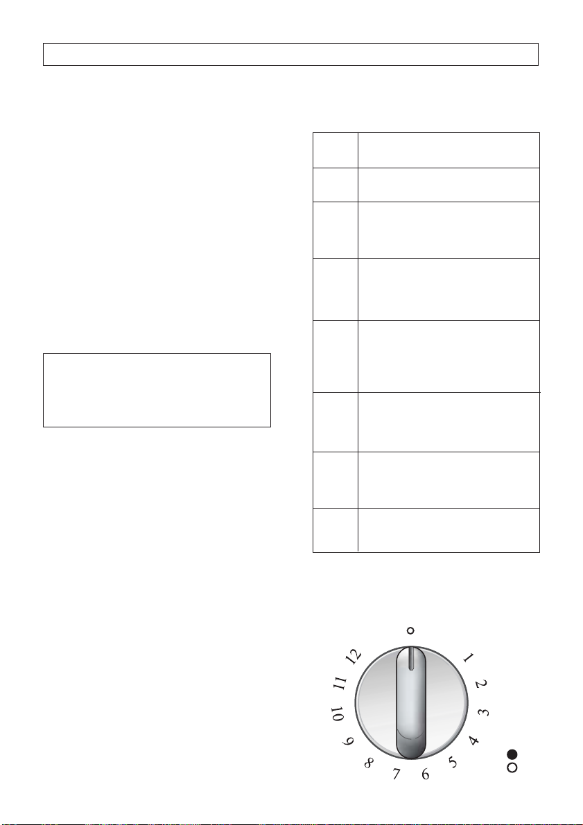
HALOGEN ZONES
The heating element consists of halogen
lamp and an electrical resistance.
It instantly reaches the required temperature.
The area is controlled by a continuous
energy regulator from 1 (minimum position) to 12 (maximum temperature).
Warning for eyes: Do not stare at the
lamp when it is on).
“HILIGHT” RADIANT ZONES
The heating element is formed of a coil
of resistant material which reaches the
working temperature quickly.
Operation of the cooking zone is controlled by a continuous energy regulator
from 1 (minimum position) to 12 (maximum temperature).
Page 10

10
GLASS CERAMIC COOKTOP
ADVICE FOR SAFE USE OF
THE COOKTOP
– Before switching on make sure that
you have the correct knob for the hotplate chosen. It is advisable to put the
pan on the hotplate before switching
on and to take it away after switching
off.
– Use cookware with flat and even bot-
toms (be careful when using cast iron
vessels). Uneven bottoms can scratch
the glass ceramic surfaces. Be careful
that the bottom is clean and dry.
– Make sure that the handles of cook-
ware do not stick out over the edge of
the cooker, to avoid them being
knocked over by accident. This also
makes it more difficult for children to
reach the cooking vessels.
– Do not lean over the cooking zones
when they are switched on.
– Do not leave objects of any type on
the surfaces made of ceramic, glass
or similar fragile material.
– Do not drop heavy or sharp objects
on the glass ceramic cooktop. If the
surface is broken or damaged unplug
the cooktop and contact the aftersales service.
– Do not put aluminium foil or plastic
objects on the cooking zones when
they are hot.
– Remember that the cooking zones
remain hot for some time after they
are switched off (about 30 min.).
– Follow the cleaning instructions care-
fully.
– If the cooktop has halogen lamps, do
not stare at them.
– If you note a crack in the cooktop,
switch the appliance off immediately
and call the After-Sales Service.
RESIDUAL HEAT INDICATOR
LIGHTS
When the cooking zone temperature is
higher than 60°C, the corresponding indicator light comes on to signal that the zone is
hot.
This light remains on even after the cooking
zone has been switched off, to signal that
the zone itself is still hot.
The cooking zones remain hot for some
time after they are switched off. During this
time do not touch the cooking zone and
make sure that children do not touch them.
The light goes out automatically when the
cooking zone temperature drops below
60°C.
TIPS FOR QUICK AND
CORRECT COOKING:
– To shorten the cooking time, when
switching on the cooktop turn the knob to
maximum. After a short time, turn the
knob to the position required for cooking.
– Use flat-bottomed cookware.
For best energy use the bottom of the
pan should be of the same diameter as
(or slightly larger than) the cooking zone.
– As the cooking zone remains hot for some
time after the cooktop is switched off,
turn the zone off a few minutes before the
end of cooking. The residual heat will
complete the cooking.
Do not scratch the cooktop with
cutting or sharp objects.
Do not use the glass ceramic cooktop as a work surface.
Page 11

11
CLEANING AND MAINTENANCE
CLEANING THE COOKTOP
AND CONTROL PANEL
● Before cleaning the cooktop switch it
off and wait for it to cool down.
● Clean with a cloth wetted with hot
water and soap or water and liquid
detergent.
● Do not use steel pads or products
which are abrasive, corrosive or chlorine based.
● Do not leave acid or alkaline sub-
stances (vinegar, salt, lemon juice
etc.) on the cooktop.
ENAMEL COOKTOP
● Enamel parts must be washed with a
sponge and soapy water or other nonabrasive products. Dry with a soft
cloth. If acid substances such as
lemon juice, tomato sauce and vinegar are left on the enamel for a long
time it will become stained.
STAINLESS STEEL COOKTOP
● Clean with special products which are
available on the market.
Note: regular use could cause discolouring around the electric hotplates,
because of the high temperature.
ELECTRIC HOTPLATES
● Clean when the hotplate is lukewarm.
● Clean with a cloth wetted with water
and salt and finish by rubbing with a
rag dampened with oil.
● Do not use water, to avoid the forma-
tion of rust.
CLEANING THE GLASS
CERAMIC COOKTOP
Make sure that the cooktop is switched
off before cleaning it.
Remove any encrustation using a special scraper which can be bought.
Remove dust with a damp cloth.
Detergents can be used, but they must
not be abrasive or corrosive.
Any remaining detergent must be completely removed with a damp cloth.
Do not put any objects on the cooktop
which can melt with heat, such as plastic objects, aluminium foil, sugar or
sugar products.
If any object melts on the cooktop,
remove it immediately (while the cooktop is still hot) using a special scraper, to
prevent any irreversible damage to the
glass ceramic surface.
Do not use knives or sharp objects
which could damage the cooktop surface.
Do not use abrasive sponges or pads
which could irreversibly damage the
glass ceramic surface.
Do not use steam jet cleaners
because the humidity could infiltrate into the appliance making it
dangerous.
Page 12

12
INSTALLATION
Technical information for
the installer
The appliance must be installed by a
qualified electrician following the manufacturer's instructions and in compliance
with local regulations in force.
To fit the cooktop into the unit make an
opening of the dimensions given in the
figure, remembering that:
– inside the unit there must be a space
of at least 30 mm between the bottom
of the cooktop and the top of an
appliance or bracket.
– any wall to the side and above the
cooktop must be at least 50 mm
away.
– the wall behind the cooktop must be
at least 50 mm away.
– when there is a wall unit or hood
above the cooktop there must be at
least 650 mm between the cooktop
and the unit or hood.
– the coatings of the walls of the unit or
appliances near the cooktop must be
heat resistant (“Y” protection against
heating in compliance with standards
EN 60335 2 6). The cooktop can then
be put near to walls which are higher
than it is (min. 50 mm).
Do not install the appliance near
inflammable materials (eg. curtains).
650 mm
50 mm
450 mm
Page 13

13
490
510
270
288
30
+ 0
– 2
+ 0
– 2
50
490
510
270
288
+ 0
– 2
+ 0
– 2
50
45
INSTALLATION
Before installing the cooktop, remove the
protective film.
This cooktop can be built into a working
surface 20 to 40 mm thick and 600 mm
deep.
To fit the cooktop into the unit make a
hole of the dimensions given in the figures
below and respect the indications given in
the previous section “Technical informa-
tion for the installer”.
Before installing the cooktop, remove the
protective film.
This cooktop can be built into a working
surface 30 to 40 mm thick and 600 mm
deep.
To fit the cooktop into the unit make a
hole of the dimensions given in the figures
below and respect the indications given in
the previous section “Technical informa-
tion for the installer”.
E30-021, E30-020, AS E30-020
E30-040, AS E30-040 - E30-050, AS E30-050
Page 14

14
A
A
A
A
20 mm min.
40 mm max.
B
DC
30 mm min.
40 mm max.
DC
INSTALLATION
FASTENING THE COOKTOP
Each cooktop is supplied with a set of
tabs and screws to fasten it on units.
– Cut the unit (as shown in the figure on
the previous page).
– Stretch gasket “D” over the edge of
the hole made, being careful to overlay the junction edges.
– Turn the cooktop over and put tabs
“A” into the mountings; only tighten
screws “B” a few turns. Make sure
that the tabs are mounted correctly as
shown in the figures at the side. Turn
the tabs so that the cooktop can be
put into the hole.
– Put the cooktop into the hole cut into
the unit and position it correctly.
– Put tabs “A” into place; tooth “C” of
the tabs should go into the hole.
– Tighten screws “B” until the cooktop is completely secured.
– Using a sharp tool cut off the part of
gasket “D” which protrudes from the
cooktop.
B
A
A
E30-040 - E30-050
AS E30-040 - AS E30-050
E30-020, E30-021
AS E30-020
Page 15

15
INSTALLATION
ELECTRICAL PART
IMPORTANT: Install the cooktop following the manufacturers instructions.
Incorrect installation can cause damage to people, animals or things, for
which the manufacturer cannot be
held responsible.
– The appliance must be connected to
the mains by a competent electrician
and according to the regulations in
force.
– The appliance must be connected to
the mains, checking first of all that the
voltage corresponds to the value
given on the rating plate and that the
section of the electrical cables can
take the load indicated on the rating
plate.
– Fit a standard plug which is suitable
for the power absorbed by the appliance.
– The plug must be put into a socket
connected to the earth system in
compliance with safety rules.
– For the United Kingdom:
As the colours of the wire of the supply cable of this appliance may not
correspond with the colours which
identify the terminals of your plug,
proceed as follows:
– the yellow/green wire must be con-
nected to the plug terminal marked
with the letter E or with the earth
symbol or coloured green or yellow/green;
– the blue wire must be connected to
the terminal marked with the letter
N or coloured black;
– the brown wire must be connected
to the terminal marked with the letter L or coloured red;
– The connection can be made directly
to the mains by putting an all-pole
switch with minimum opening
between the contacts of 3 mm
between the appliance and the mains.
– The supply cable must not touch hot
parts and must be so positioned that
it does not exceed the temperature of
75°C at any point.
– When the appliance is installed the
switch or socket must always be
accessible.
– The appliance must have its own sup-
ply; any other appliances installed
near it must be supplied separately.
NB. For connection to the mains do not
use adapters, reductions or shunts
because these can cause overheating or
burning.
If the installation requires modifications
to the domestic electrical system or if
the socket and the appliance plug are
not compatible, contact a professional
electrician. He must, in particular, also
make sure that the section of the socket
cables is suitable for the power
absorbed by the appliance.
The appliance must be connected
to the earth. The manufacturer
declines all responsibility for any
problem caused by failure to
observe this instruction.
Page 16

16
A
F
INSTALLATION
REPAIRS
Replacing the supply cable
Turn the cooktop over and unhook the
terminal board cover by inserting a
screwdriver into the two hooks “A”.
Open the cable gland by unscrewing
screw “F”, unscrew the terminal screws
and remove the cable.
The new supply cable, of suitable type
and section, is connected to the terminal
board following the diagrams shown
below.
220-240 V
SECTION OF THE SUPPLY
CABLES AND CONNECTION
DIAGRAM
Use H05RR-F cables.
The diameter of the supply cable must
not be greater than 9 mm.
220 - 240 V~ 50/60 Hz 3 x 1,5 mm
2
220/230 V
L
N
1 (L )2
PE
Page 17

A
F
220-240 V
2
3 x 1,5
220/230 V
L
1 (L )2
N
PE
Page 18

Page 19

A
A
A
A
20 mm min.
40 mm max.
DC
30 mm min.
40 mm max.
DC
B
B
A
A
E30-040 - E30-050
AS E30-040 - AS E30-050
E30-020, E30-021
AS E30-020
Page 20

490
510
270
288
30
+ 0
– 2
+ 0
– 2
50
490
510
270
288
+ 0
– 2
+ 0
– 2
50
45
E30-021, E30-020, AS E30-020
E30-040, AS E30-040 - E30-050, AS E30-050
Page 21

650 mm
50 mm
450 mm
Page 22

Page 23

Page 24

Page 25

Page 26

Page 27

Page 28

Page 29

3
5 7 6
4
2
1
3
5 7 6
4
2
1
E30-040
AS E30-040
SCHOTT
E30-050
AS E30-050
Page 30

2
1
3
5
4
1
2
E30-021
E30-020, AS E30-020
E30-021
E30-020
AS E30-020
Page 31

Page 32

SCHOTT
E30-021
E30-020 E30-040 E30-050
AS E30-020 AS E30-040 AS E30-050
Cod. 1103482 - ß
 Loading...