

Page 1
Trio-1248
Rev. 4/10
Page 2

TRIO-1248 TABLE OF CONTENTS
1.General Introduction...........................................................................................................................3
1.1 Thank you for Purchasing Trio-1248.....................................................................................3
1.2 Customer Service..................................................................................................................3
2. General Information...........................................................................................................................4
2.1 Safety....................................................................................................................................4
2.2 Compliance...........................................................................................................................4
2.3 Abbreviations........................................................................................................................4
3. Introduction........................................................................................................................................5
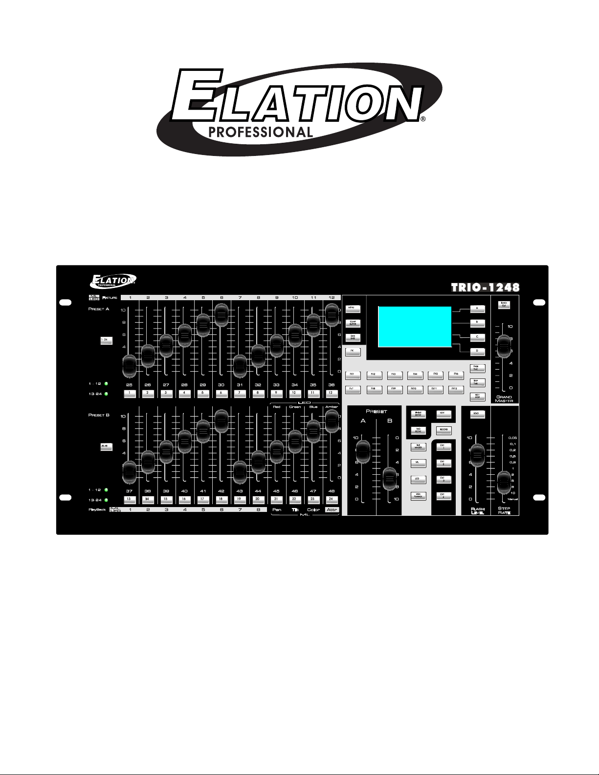
3.1 About the Trio-1248 Lighting console....................................................................................5
3.2 Unpacking.............................................................................................................................5
3.3 Caution..................................................................................................................................5
3.4 Main Features.......................................................................................................................6
3.5 Controls & Functions.............................................................................................................7
3.6 Connection Ports..................................................................................................................9
3.7 Manual Conventions...........................................................................................................10
4. Normal Operation............................................................................................................................11
4.1 Single Scene Mode.............................................................................................................11
4.1.1 Crossfade in Single Scenes..................................................................................11
4.1.2 Fade A and B Settings..........................................................................................12
4.2 Two Scene Mode................................................................................................................12
4.3 Submaster Mode.................................................................................................................13
4.3.1 Fade A and B Settings..........................................................................................14
4.3.2 Crossfade in Submaster........................................................................................14
4.3.3 Record Function....................................................................................................15
-Record Submaster.............................................................................................15
-Record Fx1 through F12....................................................................................16
-How to edit a scene...........................................................................................17
-How to Trigger Fx...............................................................................................17
-How to delete Fx................................................................................................17
-How to set EXT Keys.........................................................................................18
-Record DMX Base..............................................................................................18
4.4 ML(Moving Light)................................................................................................................20
4.4.1 Concept.................................................................................................................20
4.4.2 Menu......................................................................................................................20
-Patching Moving Light fixtures...........................................................................20
-Using Groups.....................................................................................................22
-Control Fixtures..................................................................................................24
-Preset Palette.....................................................................................................24
-Shape.................................................................................................................25
-Playback.............................................................................................................26
-Pan/Tilt Invert.....................................................................................................27
4.5 LED Mode...........................................................................................................................28
4.5.1 FIX Patch...............................................................................................................28
4.5.2 Channel Set Up.....................................................................................................28
4.5.3 Using Groups........................................................................................................29
4.5.4 Delete....................................................................................................................29
4.5.5 Listfix.....................................................................................................................30
Elation Professional® www.elationlighting.com - Trio-1248 - Page 1
Page 3

TRIO-1248 TABLE OF CONTENTS
4.5.6 Auto DMX...............................................................................................................30
4.5.7 Using Shape..........................................................................................................30
4.6 Memory Playback Mode.....................................................................................................32
4.7 Menu....................................................................................................................................34
4.7.1 Channel Set Up.....................................................................................................35
4.7.2 DMX Patch.............................................................................................................35
-Channel Patch....................................................................................................35
-DMX Patch..........................................................................................................36
-Default.................................................................................................................36
4.7.3 LCD Set..................................................................................................................36
4.7.4 Memory Lock.........................................................................................................37
4.7.5 Update Software....................................................................................................37
4.7.6 Update VGA...........................................................................................................37
4.7.7 Update DMX-BS....................................................................................................38
4.7.8 VGA Set.................................................................................................................41
4.7.9 Art Net Set.............................................................................................................42
4.7.10 Upload LIB...........................................................................................................42
4.7.11 LIB Set.................................................................................................................43
4.7.12 Change Password...............................................................................................44
4.7.13 Rev1.02................................................................................................................45
4.8 VGA Card Installation Tips..................................................................................................45
5. DMX Setup.......................................................................................................................................46
5.1 Data Cable(DMX Cable) Requirements...............................................................................46
5.2 5-pin XLR DMX Connectors................................................................................................47
6. Service..............................................................................................................................................48
6.1 Maintenance........................................................................................................................48
6.1.1 General Inspection.................................................................................................48
6.1.2 Basic Cleaning.......................................................................................................48
6.2 Trouble Shooting.................................................................................................................48
Elation Support.....................................................................................................................................49
Warranty...............................................................................................................................................50
Elation Professional® www.elationlighting.com - Trio-1248 - Page 2
Page 4

TRIO-1248 GENERAL INTRODUCTION
1.1 Thank You for Purchasing the Trio-1248
Thank you for your purchasing the Elation Professional Trio-1248 Lighting Console. Please read the
instructions in this manual carefully and thoroughly before attempting to operate this unit. These
instructions contain important information regarding safety during use and maintenance. Please fill
out and return the enclosed warranty card to validate your purchase.
1.2 Customer Service
Elation provides a toll free customer support line, to provide set up help and to answer question
should you encounter problems during you set up or initial operation. You may also visit us the web
at www.elationlighting.com for any comments or suggestions.
All returned service items whether warranty or not, must be freight pre-paid and accompany a
Return Authorization(RA) number. The RA number must be clearly written on the outside of the return
package. Items returned without a RA number clearly marked on the outside of the package will be
refused and returned at customer’s expense. You may obtain a RA number by contacting customer
service.
A brief description of the problem as well as RA number must be written down on a piece of paper
and include in the shipping container. If the unit is under warranty, you must also provide a copy of
your proof of purchase invoice.
Customer Service house are Monday through Friday 8:00a.m.-5:00 p.m. Pacific Standard Time.
Toll Free: (866) 245-6726
Phone: (323) 582-3322
Fax: (323) 832-9142
Information: info@elationlighting.com
Sales: sales@elationlighting.com
Support: support@elationlighting.com
Forum: http://forums.elationlighting.com
This manual is Copyright © 2008 Elation Professional. All rights reserved. No part of the manual
included with this product can be reproduced or transmitted in any form, by any means, for any purpose without prior written authorized permission.
Information contained in this manual is subject to change at any time and without notice. Please
contact Elation Customer Service or visit www.elationlighting.com
Elation Professional® www.elationlighting.com - Trio-1248 - Page 3
Page 5

TRIO-1248 GENERAL INFORMATION
2. General Information
2.1 Safety
The following symbols are used throughout this manual:
Indicates potential injury or death to persons.
Indicates potential damage to equipment.
Indicates items may be recycled.
The following safety information relates to the Trio-1248 Lighting Console. Please read each item
carefully to ensure you fully understand them.
To prevent the risk of electrical shock, do not open this unit. There are no user serviceable parts
inside this unit. Do not attempt any repairs yourself. Doing so will void your manufactures warranty.
Should your unit require service, please contact your nearest Elation dealer or Elation Customer
Service.
To prevent or reduce the risk of electrical shock or fire, do not expose this unit to rain or moisture.
Do not remove the plug ground pin or connect to an ungrounded circuit.
This unit is not designed for use by persons under the age of 12. Use only under adult supervision.
Turn off the power if not using this unit for a long time.
2.2 Compliance:
The CE marking (an acronym for the French “Conformite Europeenne”) certifies that a product has
met EU health, safety, and environmental requirements, which ensure consumer safety. A manufacturer that has gone through the conformity assessment process may affix the CE marking to the
product.
The Trio-1248 system has passed internal testing based on the EN55015:2001 standard, and is
100% CE compliant. We certify that the product conforms to the protection requirements of council
directives 73/23/EEC (LVD) and 89/336/EEC (EMC).
2.3 Abbreviations:
DMX – DigitalMultiplex
Gb – Gigabyte
Ghz – Gigahertz
LAN – Local Area Network
Mb – Megabyte
PC – Personal Computer
RA – Return Authorization
RAM – Random Access Memory
RGB – Red, Green, Blue
USB – Universal Serial Bus
XLR – 3 & 5-pin Cannon X connector, with Latch and Rubber guard
Elation Professional® www.elationlighting.com - Trio-1248 - Page 4
Page 6

TRIO-1248 INTRODUCTION
3. Introduction
3.1 About the Trio-1248 Lighting Console:
The Elation Trio-1248 is a three in one lighting console which was designed to control Conventional
dimmers, LED’s and Moving Lights. We are sure you’ll find your Trio to be extremely powerful and
easy to use.
3.2 Unpacking:
The Elation Professional Trio-1248 has been thoroughly tested and shipped in perfect working condition. Please take a few minutes to carefully inspect the system carton for damage that may have
occurred during shipping. If the carton appears to be damaged, carefully inspect each system component for damage, in the case that damage is found, please contact our customer support center, listed below, for further instructions. The Elation Professional Trio-1248 system carton should
includes the following:
1 Trio-1248 Lighting Console
1 External AC Adaptor
1 User Manual
3.3 Caution!
There are no user serviceable parts inside this unit. Do not attempt any repairs yourself, doing so will
void your manufactures warranty. In the unlikely event your unit may require service, please contact
your nearest Elation Professional dealer. Do not discard this carton in the trash, please recycle when
ever possible. Upon unpacking, carefully inspect your unit for any damage that any have occurred
during shipping. If damage may have occurred, do not plug the unit in, please contact your dealer as
soon as possible.
Elation Professional® www.elationlighting.com - Trio-1248 - Page 5
Page 7

TRIO-1248 MAIN FEATURES
3.4 Main Features
1. Professional DMX512 Lighting Console. Ideal for conventional, moving and LED lighting fixtures.
2. Powerful, versatile, three in one control.
3. LCD display for easy operation with contrast adjustment. (with optional VGA card).
4. USB port for uploading/downloading data and updating software. (USB Flash Drive Required...
NOT INCLUDED)
5. Artnet port for faster communication with compatible device.
6. DMX IN allows 3 pin XLR connection from external console. (Only receives data for DMX Base
playback)
7. DMX OUT’s A & B send data, via 3 & 5 pin XLR’s, to compatible fixtures/devices. DMX Output A
should only be used to send data to DMX Base fixtures/devices. DMX Output B should be used to
send data to all fixtures/devices which are patched into your TRIO-1248.
8. Buttons change color depending on their current function.
9. Grand Master control for total output control.
10. 1,152 recordable scenes (24 Pages x 48 scenes) in Submaster mode for conventional lights.
11. 24 faders control conventional, moving lights and LED fixture channels.
12. Controls 12 Moving Light fixtures with up to 40 channels each. 20 playbacks x 99 steps in
Moving Light Mode.
13. Controls 12 LED (RGB) Fixtures. 20 playbacks x 99 steps in LED mode.
14. 12 FX Keys act as multi function keys which allow the user to program and run 12 independent
chase sequences, they also act as playbacks while in DMX Base mode and are also used to enter
numeral information such as passwords during setup.
15. 6 operation modes: Single Scene, Two Scene, Submaster, Moving Light(ML), LED mode, Mem ory Playback modes.
16. Blackout button controls all fixtures. When held for 3 seconds, the blackout button overrides the
system and completely brings all fixtures to 0 (example: moving fixtures will return to their home
position rather than just blacking out.
17. Memory playback mode allows a combination of Submaster, Led and Moving Light playback.
18. Power requirement of DC 9-12V 2A power supply (Included).
19. Wireless DMX module available (optional).
20. VGA allows for 800 x 600 monitor output.
Elation Professional® www.elationlighting.com - Trio-1248 - Page 6
Page 8
TRIO-1248 CONTROLS & FUNCTIONS
At tr
1
2
3
4
5
6
7
8
9
10
11
12
1
2
3
4
5
6
7
8
ML
LED
ML
LED
TRIO -1248
ST EP
RAT E
37 38 39
40
41 4 2 43 4 4 45 4 6 47 48
25
26 2 7
28
29
30 31
32 3 3 34
35
36
LED
Pan
Ti lt
Co lo r
ML
GR AN D
MA ST ER
PR ES ET
A B
FL AS H
LE VE L
Red
Green
Blue At tr
FIX TU RE
Pl ay Ba ck
1 - 1 2
25 -36
13 .24
37 -48
Pr es et A
Pr es et B
(Manual)
10M
5M
1M
40s
20s
5.0s
2.0s
0.5s
0.2s
1 2 3 4 5 6 7 8 9 10 11 12
1- 2 4
25-48
13
14
15 16 17 18 19 20 21 22 23 24
BLACK
OUT
A
B
C
D
MEN U
CLEAR
BUFFER
FX
DMX
BASE
FX1
FX2
FX3
FX7 F X8 F X9
FX4
FX10
FX11
FX5
FX12
FX6
SINGLE
SCENE
TWO
SCENE
RECORD
NEXT
SUB
MASTER
ML
MEM
P
LAYBACK
EXT
1
EXT
2
LED
EXT
3
EXT
4
SOLO
FD/ST
TIME
STEP
GO /
STOP
Elation Professional® www.elationlighting.com - Trio-1248 - Page 7
Page 9

TRIO-1248 CONTROLS & FUNCTIONS
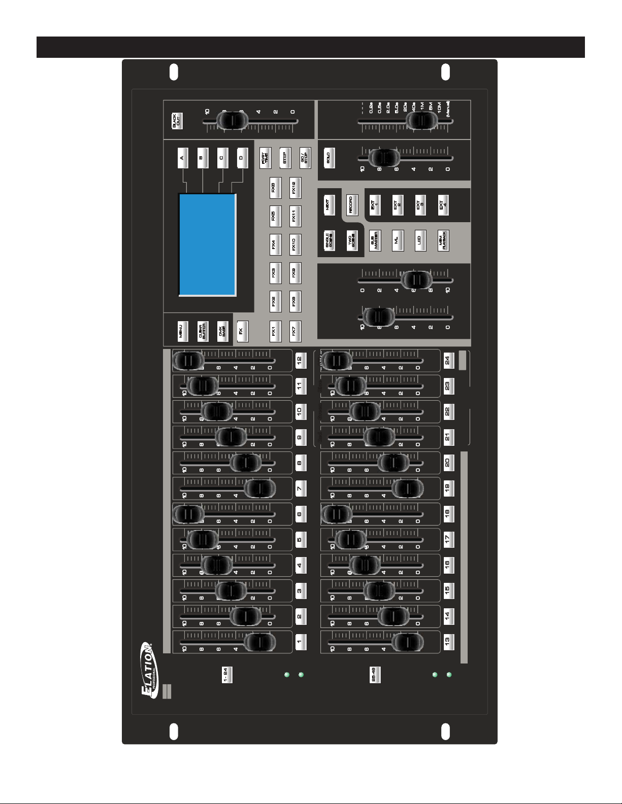
3.5 Controls & Functions
1. Key 1-24 and Key 25-48: Used to select Conventional Par’s page.
2. Bump Keys 1-24 (25-48 depending on page): Individual bump for channel relevant channel.
3. Single Scene: Used to enter Single Scene Mode.
4. Two Scene: Used to enter Two Scene Mode.
5. ML (Moving Light): Used to enter Moving Light Mode.
6. LED: Used to enter LED Mode.
7. Mem. Playback: Used to enter Memory Playback Mode.
8. Next: Used in conjunction with Preset A & B faders, Single Scene Mode, for manual Scene Cross
Fade.
9. Record: Used to record presets and submasters.
10. EXT 1-4: EXT Keys are user assignable keys that give the option to assign a single channel as a
Latch or Momentary. Latch acting as an On/Off and Momentary acting as a momentary bump.
(Example: a Fog Machine, Strobe or Blinder can be set as “Momentary” so the effect will be active
while the relevant EXT key is pressed).
11. Menu: Used to set up each parameter such as DMX channel patch, Fixture patch, update software, lock memory, etc...
12. FX key: Works in conjunction with FX keys 1-12. When the FX key is pressed, Conventional Par
Chases can be played back by pressing FX keys 1-12. FX chases 1-12 (Conventional Par Chases)
must first be programmed by the user.
13. FX Keys 1-12: are multi function keys that can be used to store/playback Conventional Par
Chases, store/trigger Playbacks when in DMX Base mode, and enter numeral information such as
Passwords when in the Menu.
14. Clear Buffer: Clears the programmer.
15. DMX Base: Works in conjunction with FX keys 1-12. When the DMX Base key is pressed,
Programs 1-12 can be played back by pressing FX keys 1-12. The DMX Base programs, can only
consist of recorded data uploaded from an external DMX console. All 12 chases can run simultaneously.
16. FD/ST Time key: This is a multi function key. FD represents “Fade Time”. When Fade Time is
active, its key will illuminate Red. ST represents “Step Time”. When Step Time is active, its key will
illuminate Yellow. Fade and Step times can be adjusted by moving the “Step Rate” fader.
17. Step key: Used to store steps while programming FX 1-12 (Conventional Par Chases) and to
manually step through ML and LED program steps.
18. Go/Stop: Used to start/stop playback of FX 1-12 (Conventional Par Chases).
19. Solo key: Works in conjunction with the “Flash Level” fader. When in Single and Two Scene
modes, pressing bump keys 1-24, will give you temporary output override based on the Flash Level
fader setting.
20. Faders 1-24 (25-48 depending on active page): Each fader can be soft-patched to control one or
more channels. i.e. - Fader 1 can control channels 1,5,10 & 20 simultaneously.
21. Preset A and Preset B faders: Work in Single and Two Scene Preset modes. In Single scene
mode, these faders are used to activate the “Next” function. In Two Scene mode, these faders control Preset A & B intensities for channels 1-12 & 13-24.
22. Flash Level: Represents the max bump output value for all Conventional Par channels.
23. Step Rate: Used to set hold and fade times for all programs during record process and during
playback.
24. Grandmaster: Controls output of entire console at all times.
Elation Professional® www.elationlighting.com - Trio-1248 - Page 8
Page 10

TRIO-1248 CONNECTION PORTS
1 2
3
4
5 6
3.6 Connection Ports
1. DC IN : Connects the power source with DC 9-12V, 2A Max. (Included).
2. ArtNet: Connects ArtNet with compatible fixtures/devices.
3. USB: Connects any universal USB drive so that data can be uploaded and downloaded to and
from the TRIO.
4. VGA: (Optional Slot) Connects monitor, 800x600 max pixel resolution, via VGA connection.
5. DMX IN: Connects and receives DMX signal from any universal DMX console (Receives Data
Only).
6. DMX OUT:
-Port A: Outputs DMX signal for DMX Base Playback only (Recorded programs from an external control source).
-Port B: Outputs DMX signal for all data patched and programmed in your TRIO.
Elation Professional® www.elationlighting.com - Trio-1248 - Page 9
Page 11

TRIO-1248 MANUAL CONVENTIONS
3.7 Manual Conventions
The following terms and conventions are used throughout this manual:
• Keys are presented using their exact spelling and capitalization and surrounded by brackets (i.e.
press the [1-24] key).
• Activate is used with keys that toggle between two values or functions and means place the control in its active state.
• Deactivate is used with keys that toggle between two values and means place the control in its
non-active state.
• Select describes pointing to and clicking a button or checkbox (on a software screen) such that
it is activated. This allows a single instruction to describe this action without knowing the control’s
previous state. For example, if the control is not selected, clicking the control once selects it. If it is
already selected, no action is required.
• Highlight describes the outlining of selected text or files with a colored border to make it stand out.
For example, this text is highlighted. Text may be highlighted by clicking and dragging the cursor
across the portion desired.
This manual is Copyright © 2010 Elation Professional. All rights reserved. No part of the manual
included with this product can be reproduced or transmitted in any form, by any means, for any purpose without prior written authorized permission.
Information contained in this manual is subject to change at any time and without notice. Please
contact Elation Customer Service or visit www.elationlighting.com for the latest manual revisions.
Elation Professional® www.elationlighting.com - Trio-1248 - Page 10
Page 12
TRIO-1248 OPERATION - SINGLE SCENE MODE
PRES ET
A B
PRES ET
A B
4. Operation
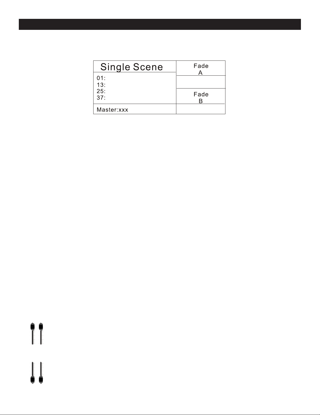
4.1 Single Scene Mode:
When you power the unit on, the LCD will show you.
4.1.1 Single Scene Crossfading
A crossfade allows one scene to fade out while another scene fades in.
In Single Scene Mode, when “NEXT” is active, the Trio will function like a single scene crossfading
console. Crossfade times can be preset or manually set on the fly.
1. Activate Single Scene Mode, green backlite key will indicate that it is active. Activate A and B
Preset Faders to their top position. Activate the Grand Master fader to its top position. Activate the
“Next” key- red backlite key will indicate that it is active. Adjust the Channel Faders (1-24) to set the
Channel values as desired for your first Scene. Those channels should now be active.
2. Activate A and B Preset Faders to their bottom position. Previously set channels will remain active.
Adjust Channel Faders (1-24) to set the Channel values as desired for your next Scene.
3. Activate A and B Preset Faders to their top position, at the rate that you want your new scene to
fade in at. Your previous scene should fade out while your new scene fades in. See section 4.1.2
“Fade A and Fade B Settings” to preset Cross fade times.
4. Repeat steps 1-4 to continue using the Crossfade “Next” function. To exit the “Next” function,
Activate A and B Preset Faders to their top position and deactivate the “Next” key.
*Note:
1. In Single Scene (yellow backlite key), Two Scene (yellow backlite key) and Submaster modes (red backlite key),
one or more channel bump/scenes can be set active based on the Flash Level fader setting. To do so, while in one
of the forementioned modes, hold down the bump button or buttons for channels or scenes that you want active.
Then activate one of the other two modes. The selected channels will remain active while all other channels or
Submasters can be bumped or activated. While the Single and Two scene indicator’s are yellow, all function keys
are void except for the grandmaster.
2. There are two ways to switch to Single Scene mode from any of the other Modes:
2.1 Crossfade
-Crossfade allows the user to transition smoothly between the current working mode
to Single Scene. Activate the Single Scene key- the yellow indication Insert means the
current fader settings are still in the previous scene. By activating the A and B Preset
Faders bottom to top, the indicator will now be green and the user will not be working
in Single Scene Mode.
2.2 Shortcut
-This method allows the user to transition quickly from the current working mode into
Elation Professional® www.elationlighting.com - Trio-1248 - Page 11
Page 13
TRIO-1248 OPERATION - SINGLE SCENE MODE
Single scene mode. Activate the Single Scene key once to change the indicator to yel
low which means the console is running on the current fader settings. Activate the Single Scene key
a second time to switch to Single Scene mode-indicated by the green backlite.
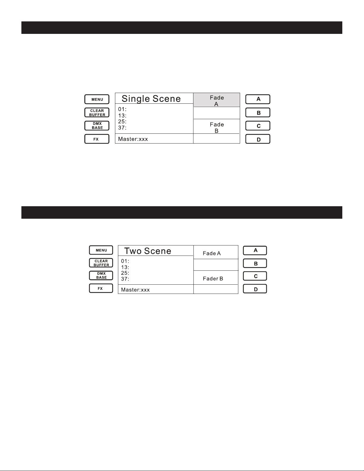
4.1.2 Fade A and Fade B Settings
1. Activate Softkey A to choose and highlight “Fade A”.
2. Adjust Step Rate fader to set the Fadetime for Preset A.
3. Deactivate Softkey “A”.
-Just as above, Activate Softkey C to choose and highlight “Fade B” and set a desired fade time
using the Step Rate fader.
TRIO-1248 OPERATION - TWO SCENE MODE
4.2 Two Scene Mode
1. When Two Scene Mode is entered by pressing the Two Scene key, the LCD Screen will show this
display:
The Channel Faders on the page represent Scene A and Scene B
Faders 1-12 control Scene A
Faders 13-24 control Scene B
When Preset A and B Faders are in the Top position, the LCD will perform Scene A and Fade out of
Scene B. When the Preset A and B Faders are in the bottom position, the LCD will perform Scene B
and fade out of Scene A.
Pushing A and B Preset Faders simultaneously allows smooth transition between Scenes.
2. If it is desired to switch into Two Scene Mode from another work mode, the user may do so in the
same fashion as Single Scene Mode.
2.1. CrossFade
2.2. Shortcut
-Refer to the details in Single Scene Mode.
Elation Professional® www.elationlighting.com - Trio-1248 - Page 12
Page 14

TRIO-1248 OPERATION - SUBMASTER MODE
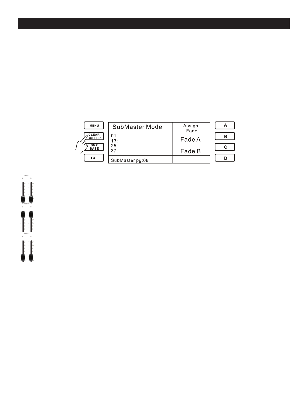
4.3 SubMaster Mode
When SubMaster mode is activated, the LCD Screen will show this display:
In this mode a total of 1152 Submasters are available - 24 pages x 48 Submasters per page.
1. Recording Submasters
Submaster Mode allows you to record a scene or look into each fader.
1.1 To record a Submaster, the console must either be in Single Scene Mode or Two Scene Mode.
While in either Single Scene or Two Scene Mode, the Submaster is created by the faders being
adjusted in either of theses modes, then switching into Submaster Mode to then record and play the
Submaster.
-Refer to the Record Function Section for details.
2. Submaster Pages
To change Submaster pages, hold down the SubMaster key. The LCD will show you the current
page. Use the Bump Buttons to select the desired page.
-Any recorded Submasters on each page will display red (half intensity) on the Bump Buttons
3. Assigning Fade Time for a SubMaster
3.1 Press the A Key to highlight the Assign Fade Function.
3.2 Hold down the Bump Button of the desired recorded Submaster and adjust the StepRate Fader
to modify the Fade Time.
Elation Professional® www.elationlighting.com - Trio-1248 - Page 13
Page 15
TRIO-1248 OPERATION - SUBMASTER MODE
4.3.1 Fade A and Fade B Settings
-The user may set the DMX value for both Fade A and B
1. Push Softkey B to choose and highlight Fade A
2. Adjust StepRate Fader to set the Fade Time for Preset A
3. Push Softkey B a second time to erase the selection
4. Repeat above action to set Fade B using Softkey C
Fade A and Fade B can be chosen simultaneously by using the StepRate Fader to set the same
FaderTime for Preset A and B.
If the user wants to switch into Submaster Mode from another work mode, the console will keep the
current fader settings as the background scene. If the user wants to cancel the current fader settings, simply press the Clear Buffer key to release the fader settings.
4.3.2 Crossfade in Submaster
The user may Crossfade in Submaster Mode. Begin by setting Preset A and B Faders in the
bottom position.
Move the Preset A and B to the top position- the first recorded bump indicator will blink yel
low.
Move the Preset A and B faders toward the bottom position to fade in the first Scene - the
first recorded fade stop blinking as the scene fades in.
Additional Information for Crossfading:
1. To stop a crossfade, move only the Preset A Fader down and then back up. This will fade out the
last output scene.
2. Changing the Work mode will also stop the crossfade immediately and take out the last fade.
3. Any empty Submasters, Submasters with effects or Submasters that already have a level will be
ignored. Example: If any of the Submasters are already in the up position (output), the sequential
crossfade will start from the scene immediately after the highest outputting fader (i.e. If fader 1, 3,
and 5 are up, the crossfade will start from scene 6.)
4. The LCD will show the fader percentage values for both the fade in and fade out as the fade is
occurring.
Elation Professional® www.elationlighting.com - Trio-1248 - Page 14
Page 16
TRIO-1248 OPERATION - RECORD FUNCTION
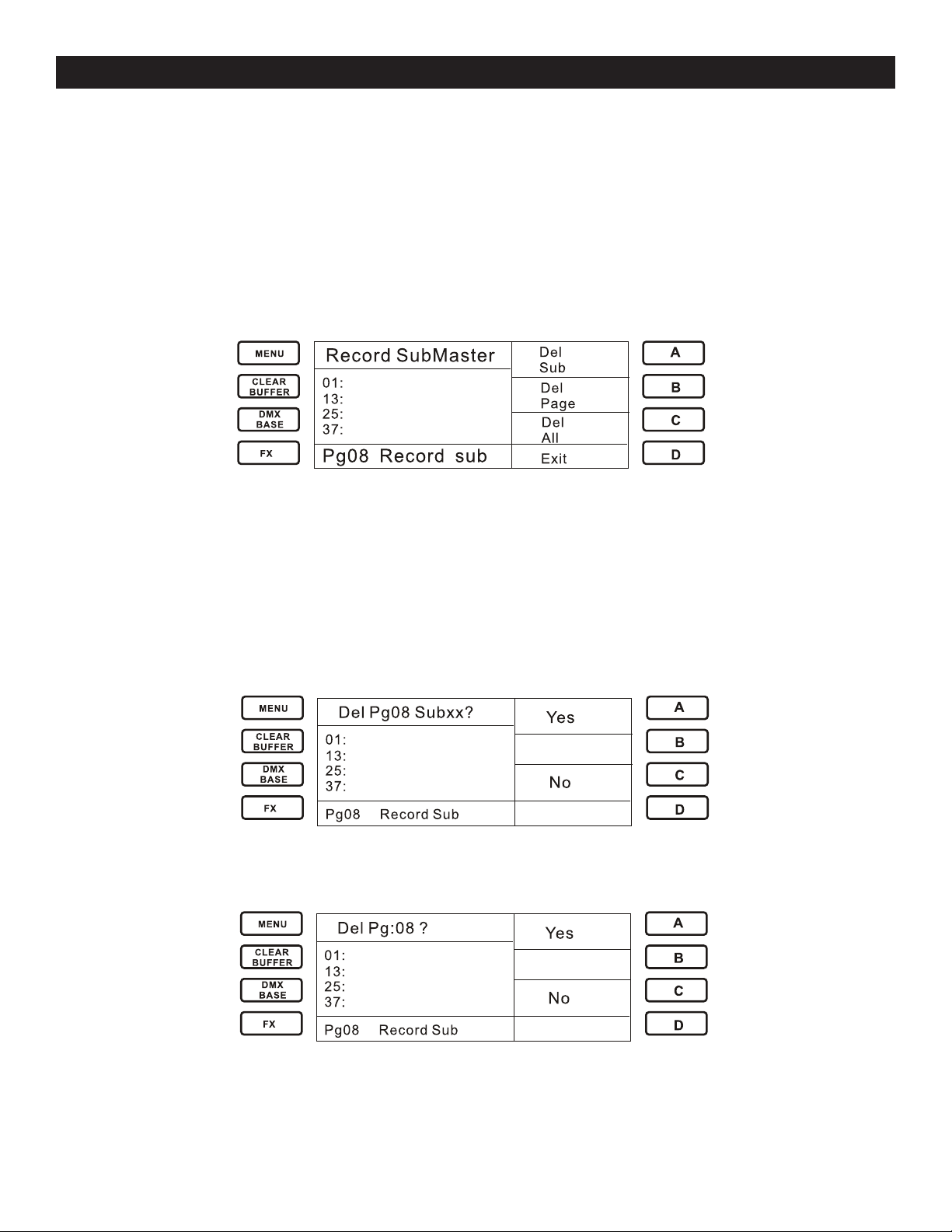
4.3.3 Record Function
1. Record a Submaster
To record a Submaster the console must be in either Single or Two Scene mode in order to adjust
fader levels.
1.1 Push Record Key to illuminate the Record indicator. If the Channel is blank the bump button for
that channel will flash. If the Submaster is recorded on that channel, the Bump will black out.
1.2 Adjust the StepRate fader to set the Fadetime for the Submaster
1.3 To assign the Submaster to a Bump, push the Bump key that is desired to contain the
Submaster.
-Repeat actions for additional Submaster recordings
After the Submaster is recorded, the indicator will illuminate red and the Record key will black out.
Also while in Submaster Record mode, the user may select the functions “Del Sub”, “Del Page”, or
“Del All”.
Press the Bump of the Submaster you want to Delete. Press the A key to choose “Del Sub” as the
LCD screen shows you below. Press A to to confirm “Yes” or C to exit.
To Delete the entire Page, press the B key to choose “Del Page”, as the LCD shows you below.
Press A to confirm or C to exit.
To Delete all of the Submaster and Pages, press the C key to choose “Del All” as the LCD screen
shows you below. Press A to confirm or C to exit.
Elation Professional® www.elationlighting.com - Trio-1248 - Page 15
Page 17

TRIO-1248 OPERATION - RECORD FUNCTION
2. Record Fx1- Fx12
FX Keys are multi function keys that can be used to store Chases, Trigger Playback in DMX Base,
and enter numeral information such as Password.
FX Keys allow the user to program scenes and chases as independent Submasters. They can run
regardless of the work mode with 99 Steps max per FX.
To record Fx1- Fx12 the console must be in either Single or Two Scene mode in order to adjust
Faders.
2.1Push the Record key. The Record key will illuminate.
2.2 Push the Fx1- Fx12 that you want to Record. Example: Fx1
2.3 The Fx1 key will illuminate blue. The LCD screen will then display the information for Fx1.
Sxxx represents the current Step
Txxx represents the total number of Steps
2.4 Press the Step key to record the scene and run Sxxx and Txxx. After the Scene is completed for
FX1, press the Step key and the Scene can be recorded to the current Step.
2.5 If you want to delete/cancel a Step, choose the desired Step using button C (Next) or D (Back).
Push the A button (Del Step) to delete the Step.
2.6 To insert a Scene before a Step, use the C (Next) or D (Back) buttons to select the step desired
to have the scene precede. Push the Step key to insert the Scene.
Elation Professional® www.elationlighting.com - Trio-1248 - Page 16
Page 18

TRIO-1248 OPERATION - RECORD FUNCTION
2.7 To adjust the FadeTime and StepTime for an Fx, push the FD/ST Time key. The FD/ST key will
illuminate: Red representing FadeTime and yellow representing StepTime. Adjust the StepRate Fader
to set the Fade/Step time as desired.
2.8 Push Fx1 again to complete.
2.9 Push Record to exit Record Mode.
3. How to Edit a Scene
In Record Fx Mode, push the Key of the desired Fx to be edited. The Bump indicators will illuminate
with a flashing red. Push the Fader of the Bumps you want to edit. Push the FD/ST key and its’ Fader
or StepRate Fader to set your value (Fadetime and Steptime). Push the Step key to Record the value
to the current Step. Repeat these actions for any additional Steps desired you want to edit.
After editing is completed, press the Fx button of the Fx you are working on to record the value.
Repeat these actions for all Fx.
4. How to Trigger FX
After the recording is complete, the Fx channels that have recorded sequences will illuminate red.
Press the Fx Key of the desired Fx- the indicator will illuminate and blink yellow. Press the Go/Stop
key to begin the Fx. The Fx key will then blink red and run in sequence (Runstep).
To stop the Fx from running, press the Fx key again. The indicator will blink yellow. Press the Go/
Stop key again to stop the sequence and the indicator will return to a sold red illumination.
*Note - A maximum of 12 Chases may run at the same time with 99 Steps per Chase.
5. How to Delete Fx
In Record Fx mode, Press the B key to choose Del FxBase. Choose the Fx you wish to Delete by
pressing the corresponding Fx key. Press the A key to confirm or the C key to cancel.
Elation Professional® www.elationlighting.com - Trio-1248 - Page 17
Page 19

TRIO-1248 OPERATION - RECORD FUNCTION
6. How to Set EXT Keys
EXT Keys act as direct bump buttons for channels 49 through 52. They can be linked to a conventional fixture, or a fog machine. The user has the option to have the EXT Keys to act as bumps or
on/off switches.
EXT Keys cannot be built into a Submaster or a Chase.
When the Channel Setup screen is entered, the user will notice that there are 52 channels set for the
dimmers when there are only 48 Faders on the console to control them. The additional 4 dimmers
are linked to the EXT Keys. The user has the option to have the EXT Keys to act either as a Bump or
on/off switch.
7. Recording DMX Base
The Trio-1248 also allows you to record DMX data form an external DMX device to DMX Base- this
action is referred to as DMX Base Record.
In “Record Submaster” Mode, press DMX Base” and press any Fx1-Fx12 key. This will switch the
console into “Record DMXBase” mode.
BBT Record:
BBT stands for “Blackout Blackout Technology”. This was created so chase/show sequences would
loop seamlessly. The idea is to write a blackout step at the beginning of a chase or show and a
blackout step at the end of the chase or show so the controller will automatically recognize the
blackout steps and will loop the chase or show seamlessly on playback.
The user only needs to use the BBT Record function if using an external console to record a Chase
into the Trio-1248. The user must make sure to insert a blackout at the beginning and the end of the
Chase.
Press the A key to confirm
Press the C key to Exit
DMX Record:
To choose DMX Record, Press the A key to confirm, then Select “Start”. The console will then begin
recording all the DMX information.
Delete Base:
Used to delete a single DMX Base file.
Del All:
Used to delete all DMX Bases data.
Elation Professional® www.elationlighting.com - Trio-1248 - Page 18
Page 20

TRIO-1248 OPERATION - ML MODE
4.4 ML Mode (Moving Light)
4.4.1 Concept
A maximum of 12 Moving Lights can be controlled by the Trio-1248. A maximum of 40 attributes for
each moving light and a maximum of 512 channels of DMX output can be assigned.
A maximum of 20 Playback can be recorded with 99 Steps for each Playback. Each Step has its own
FadeTime and WaitTime
The Bank of the moving light is saved at: TRIO1248/FLIB. The first level is the file of the moving light
manufacturer. The second level is the file of the moving light from the manufacturer.
4.4.2 Menu
In ML Mode, press the Menu key and the LCD will display:
1. Patching Moving Light Fixtures
Each ML fixture needs to be assigned to a preset fader on the console. This makes it easier to control each specific fixture.
The bottom fader and the buttons below them are called the handle for the fixture because it is used
to control the fixture. The fader will control the intensity of the fixture and the button is used while
programming to select the fixture.
You must also specify what type of fixture is allocated to each handle. Once you have entered this
information, the console can tell you the DMX address to set on your fixtures to match the settings it
is using.
This setup process is called Patching.
You can Patch up to 12 fixtures on the Trio-1248.
1.1 Patching Moving Light Fixtures
A Moving Light can have many attributes such as pan, tilt, color, gobo etc.
The Trio-1248 has personality files available for most fixtures in the lighting world. Both these and
the latest software are available on elationlighting.com on the Trio-1248 page. The user must upload
these files with a USB Flash Drive.
The Trio-1248 will automatically recognize the personality profiles as previosly named. Due to this
fact the user should never rename the profile as this will render the console unable to recognize and
retrieve the profile.
The user may patch a fixture by following the steps below.
-Make sure you have inserted a USB Flash Drive with the fixture profiles stored on it.
-Press Menu and the LCD will display:
Elation Professional® www.elationlighting.com - Trio-1248 - Page 19
Page 21

TRIO-1248 OPERATION - ML MODE
-Press the A key to choose “Fix Patch”
-The console will read the moving lighting files of each manufacturer from the USB disk.
-Use “More” or “Back” to select the moving light you desire. Press D to choose “Enter” for
confirmation of your selection.
-The LCD will show you the name and patched DMX address of the fixture. If you want to
modify the assignment of the DMX address, you can use Fx1-Fx10 to change the address.
The Fx10 means 0 and the Fx1-Fx9 means 1 though 9 in order.
-To Patch a single Fixture, press a handle Bump button. To Patch a range of Fixtures, hold
down the Bump button for the first fixture in the range. Press the last Bump button in the
range. The range of fixture will be patched to the same DMX address.
-Repeat the above steps to patch any additional Handles.
1.2 Editing and Recording various Scenes for a patched Moving Light.
The Trio-1248 allows you to edit and record various scenes for a patched moving light. You may set
the Pan, Tilt, Speed, Color and Attribute for it.
1.2.1 In ML Mode, Press the Record button.
1.2.2 Press a bump that has a Moving Light patched into it(ex. Bump1). The indicator will illuminate
red and the LCD will display the Moving light you have patched.
1.2.3 Press the bump of the channel you want to record the scene in. Use its fader to control the
patched moving light in the Bump. Select “Playback 1”- it will blink red. The LCD will display:
1.2.4 Press the D key to select Next, and then the Shape
1.2.5 Press the A key to select circle. Then select Next.
Elation Professional® www.elationlighting.com - Trio-1248 - Page 20
Page 22

TRIO-1248 OPERATION - ML MODE
1.2.6 Push the fader of “Pan” and “Tilt” to adjust the value
1.2.7 Press the A key to select “Speed”. Then adjust the StepRate Fader to the Speed value. Press
the B key to have it Run
1.2.8 Press Menu to return to the Record Playback interface.
Press the D key to select “Attrib”.
1.2.9 Press the soft key A-B to select the attribute you desire. Press the Playback 1 to assign these
settings as Step 1.
1.2.10 Repeat the above action to complete any additional Steps
1.2.11 After you are finished adding Steps, press Record to record the settings for the Moving Light
patched in to a Bump.
Likewise, this method can be used to edit and record Scenes for other patched Moving Lights or to
assign a different Fader to control a patched Moving Light.
*Note: Make sure the operation interface is in “Record Playback” prior to recording any value as a
Step(by pressing Menu button). Otherwise, it is void when you try to press “Playback” bump to set a
chase step.
2. Using Groups
If you have several units of one fixture type, you often want to select them all at the same time. To
avoid excessive Bump button use, the Trio-1248 allows you to put fixtures into groups which you
can use to select all fixtures by typing the group Bump.
2.1 Making A Group
You may make a Group by following these steps:
-Select the Fixture you want to put into the Group
-Press Menu, then the C key to choose “Record Group”
-The Bump 1-12 will indicate the recording state for the group. The blue blinking means the
Bump is blank. The Blackout Bump indicates it already has recorded content in it.
-Press Bump 1-12 to assign the Group.
2.2 Selecting a Group of Fixtures
Once you have created a Group, you can the quickly select all of the fixtures in the group.
-In ML Mode, press the B key to highlight “Recall Group”.
Elation Professional® www.elationlighting.com - Trio-1248 - Page 21
Page 23

TRIO-1248 OPERATION - ML MODE
-Bump LED will indicate the recorded groups by blinking blue.
-Press the related Bump. The Fixture that was recorded in the Group will be selected and the
others will not be selected.
2.3 Deleting
The Trio-1248 allows the user to delete the collocated Moving Light and recorded Chase.
2.3.1 Delete Fix
-In ML Mode, Press the Menu key. Choose Next and then Delete
-To choose Delete Fix, the Trio-1248 gives you the option to delete a single Fixture or All
Fixtures.
-Choose Delete One to delete a single fixture. The LCD shows “Press a Preset <Bump> to
Delete.”
-Choose “Yes” to confirm the delete, choose “No” to exit.
-Choose “Delete All” to delete all of the recorded Chases
-Choose “Yes” to confirm, choose “No” to exit
2.3.2 Delete Chase
-In ML Mode, press Menu, choose Next and then Delete.
-To choose Delete Chase, the Trio-1248 gives the user the option of deleting a single Chase
or all Chases.
-Choose Delete One to delete a single Chase. The LCD will show “Press Playback <Bump> to
Delete.”
-Choose Delete All to delete all recorded Chases
-Choose Yes to confirm, choose No to exit.
2.4 List Fix
The List Fix function will help the user to easily view the collocated fixtures and the corresponding
DMX address.
-In ML Mode, press Menu, choose Next and then choose List Fix
-The LCD will show you the name of the collocated Fixtures in their DMX Address.
Elation Professional® www.elationlighting.com - Trio-1248 - Page 22
Page 24

TRIO-1248 OPERATION - ML MODE
2.5 Auto DMX
This function will auto sort the DMX address in sequence for those collocated Fixtures.
-In ML Mode, press Menu, choose Next and then choose Auto DMX
-Choose Yes, the Moving Lights will sort in sequence
-Choose No to exit
3. Controlling Fixtures
3.1 Selecting Fixture
Select the Fixtures that you want to control using the bump buttons. You can select fixtures individually or several at a time. You can control fixtures directly with the fader control of the bump. The
value is the exact figure of the Fader. The attribute of Pan, Tilt, and Color for the Moving Light is
controlled by the Pan, Tilt, Color Faders. The other attributes of the Moving Light should be selected
by softkey. While the Fader is pushed upward the value is increased, and when the Fader is pushed
downward the value is decreased. If you press the Bump (of Pan, Tilt...) to hold the output value, the
value will not change while adjusting the Fader.
3.2 Selecting the other Attributes of Moving Light
-In ML Mode, press the Bump button that the desired Moving Light fixture is allocated to.
-Press the related softkey to assign attributes to the Attribute Fader. Adjust the Attribute
Fader to control the Attribute value.
3.3 Using the Clear Buffer key in ML Mode
While the user sets channel values of a Moving Light, the console provides a space for its channel
information. This is called the “Scene Buffer”. If the user wants to clear up the channel information, the ClearBuffer key should be used to clear it. It is recommended that the CLEAR BUFFER key
pressed after each scene has been saved to a playback.
4. Preset Palette
When controlling a fixture, you may find that you frequently use specific positions, colors, gobos,
etc. Like an artists palette, your console allows you to recall them. There are 10 pages of 10 palette
entries. The Preset Pallettes must be created in the Trio Profile creator program. When your fixture is
patched to your Trio, all pallette information will also load.
Recalling a Palette Value
Select the fixture to be changed. Shared palettes can be set to all fixture of the same type.
-In ML Mode, press the Bump button in which you have allocated the ML fixture to.
-Press the A key to choose Preset Pallet. The LCD display will show:
Elation Professional® www.elationlighting.com - Trio-1248 - Page 23
Page 25

TRIO-1248 OPERATION - ML MODE
ML Palette
01.
Colors
ME NU
CL EA R
BUF FE R
FX
DM X
BA S E
A
B
C
D
Fade Tim e:2 4.0
02.
Gobos
03.
Positi
More
Pan: 128
Til t: 000
Color: 230
Dimmer: 16 4
Gobo: 000
-Now press the related softkey A-D to choose the Palette you wish to select.
5. Shape
Your console has a shape generator. It allows you to quickly create exciting light shows using many
movements and changes with a minimal amount of programming.
A shape is simply a sequence of values which can be applied to any attribute of a fixture. A “circle”
shape, for example, applied to the Pan and Tilt attributes, would cause the fixture to move its beam
around in a circular pattern. You can set the center point of the circle, the size of the circle and the
speed of the movement.
5.1 Selecting a Shape
In ML Mode, when you choose a Shape, it will be applied to all selected fixtures.
-Select the fixture that you want to apply a shape to
-Select Shape
-The LCD will display:
-Select Stop, this will stop all running movements:
-Select Circle, the LCD will display:
“Center Pan”: the center value of Pan when the moving light runs its shape.
“Center Tilt”: the center value of Tilt when the Moving Light runs its shape.
CW” and “CCW”: the direction of the shape. CW=Clockwise, CCW=Counter Clockwise
“Speed”: the speed that the moving light runs its shape.
“Run”: to start the shape.
Elation Professional® www.elationlighting.com - Trio-1248 - Page 24
Page 26

TRIO-1248 OPERATION - ML MODE
-Select Fan, then select Wave. The LCD will display:
“Pan Radius”: the radius of the Pan. Adjustable between 01-45.
“Tilt Radius”: the radius of the Tilt. Adjustable between 01-45.
“Wave Number”: how many waves will be driven. Maximum # of 12 waves.
-Select “Figure”. this represents a figure 8 movement.
The LCD will display:
6. Playback
6.1 Programming a Chase
To program a chase, you have to set up the lighting for each step of the chase, then save it. The contents of the programmer are recorded as a step.
-Select Record
-Blank Playbacks will blink red. A programmed Playback will be off.
-Press the bump button of the playback where you want to store the chase.
-Set your scene for the Step.
-Set Fade time and Step time for the step by using the “FD/ST” key and “Step Rate Fader”.
-Press the Bump button of the playback to store the programmer contents as step 1 of the
chase.
-Press the ClearBuffer (unless you want to re-use the contents of the programmer), then
repeat step 4-6.
-Press Record to finish when you have stored all your desired steps. (99 max steps allowed)
*Note
-Press ClearBuffer when you have finished saving the Chase. Otherwise, when you try to play
back, the programmer will include previously set values and you won’t see the chase properly.
-There are up to 99 Steps in a Chase.
Elation Professional® www.elationlighting.com - Trio-1248 - Page 25
Page 27

TRIO-1248 OPERATION - ML MODE
Fixture Menu
Pan
Normal
ME NU
CL EA R
BUF FE R
FX
DM X
BA S E
A
B
C
D
Fade Tim e:2 4.0
Til t
Normal
Enter
Set Cur ren t
Fix
Runway
6.2 Running a Chase
To run a chase, raise the fader of the playback to its top position. The chase will start to run.
-The HTP (intensity) channels in the chase will be controlled by the Fader. The other chan-
nels (LTP) will be set as soon as the fader moves above zero according to the LPT fader times
programmed in the chase. You can set the point at which the LPT channels activate from the
Fixture Library File.
-To stop a chase, pull the Fader back down to zero. The chase will stop and the user can
manually control the Chase Steps.
-When running the Playback, pressing the corresponding Bump will cause it’s indicator to turn
yellow.
-Pressing Step will cause the Chase to run Step by Step
-Pressing the corresponding Bump an additional time will erase the manual control
7. Pan/Tilt Invert
In Fixture Menu, the Pan/Tilt of a moving light may be changed between Normal and Invert.
Prior to setting the Pan/Tilt Invert, it is required to select an allocated Moving Light.
-Press the Bump button that you have allocated with a Moving Light.
-Press B to select “Pan/Tilt Invert”, the LCD shows the above figure.
-Press A to change between Pan Normal and Pan Invert.
-Press C to change between Tilt Normal and Tilt Invert.
-Press D to select Enter and confirm settings.
-Press Menu to return to the previous menu.
Once you complete the settings for Pan/Tilt Invert, push the Pan/Tilt fader up or down, the Moving
Light will react as you set it.
Elation Professional® www.elationlighting.com - Trio-1248 - Page 26
Page 28

TRIO-1248 OPERATION - LED MODE
4.5 LED Mode
Similar in operation as in ML mode, LED mode allows for much of the same operation. Your console
is able to control a max of 12 LED (RGBA) fixtures.
Press the Menu button, the LCD screen shows you:
4.5.1 Fix Patch
An LED fixture can have many attributes, such as Red, Green and Blue control channels.
You must first load your profiles from a USB Flash Drive that contains the files obtained from elationlighting.com.
The user may patch a fixture according to the following steps:
-Make sure you have inserted the USB Flash Drive with files already loaded onto it.
-Press A to choose “Fix Patch”.
-The console will read the LED files of each manufacturer from the USB device
-Use “More” or “Back” to select the LED you desire
-Press D to choose “Enter” for confirmation of the selection
The LCD will show you the name and auto patched DMX address for the fixture. If you want to modify the assignment of the DMX address, you can use FX1-FX10 to change the address. The FX10
means 0 and the FX1-FX9 means 1-9 orderly.
To patch a single fixture, press a desired bump button. To patch a range of fixtures, press and hold
down the bump button for the first fixture in the range, then press the last bump button in the range
then release both bump buttons simulaneously. The fixtures will be patched to all locations between
the selected bump buttons with sequential DMX addresses.
Repeat the above steps to patch additional fixtures.
4.5.2 Channel Set Up
The Channel Set Up option allows the user to softpatch the start and end DMX address for Dim
(dimmer channels), LED and Moving Lights fixtures.
Elation Professional® www.elationlighting.com - Trio-1248 - Page 27
Page 29

TRIO-1248 OPERATION - LED MODE
-Use “>” to move the cursor to the parameters you want to modify.
-Use “Up” or “Down” to gradually set the corresponding value.
-Use “Flash Level Fader” to change the corresponding value rapidly.
-Choose “Enter” to save your settings and exit.
4.5.3 Using Groups
Your console is able to store up to 12 groups. If you have several fixtures of the same type, you often
want to select them all at the same time. To avoid excessive use of the Bump buttons, the console
allows you to put fixtures into groups.
Making a Group
Make a Group by following these steps:
-Select the Fixtures that you want to put into a group.
-Press the Menu button, then Press C to choose “Edit Group”
-Bump buttons 1-12 will indicate the recording state for the Group. Blue blinking keys indi cate the group is blank, a non blinking key indicates that the bump contains a group.
-The LCD prompts you with “Record Group Select a Bump as a Group”. Press any one of the
bumps (1-12) to store your group.
Selecting a group of Fixtures
Once you have created a Group, you can then quickly select all of the fixtures in the Group.
-In LED Mode, press A to highlight “Group”.
-Bump LED’s, with groups stored, will light in blue.
-Press the related bump button which contains the group that you want selected.
4.5.4 Delete
The console allows the user to delete the collocated LED fixture and Recorded chases.
Delete Fix
-In LED Menu Mode, choose Next and then choose Delete.
Elation Professional® www.elationlighting.com - Trio-1248 - Page 28
Page 30

TRIO-1248 OPERATION - LED MODE
Master: xx x
Delete Menu
Exi t
Delete
One
A
B
C
D
ME NU
CL EA R
BUF FE R
FX
DM X
BA S E
Delete
All
Master: xxx
Led Shape
Exit
Rain
bow
A
B
C
D
MEN U
CLE AR
BUF FE R
FX
DMX
BAS E
Knight
Rider
Chase
-Choose “Delete Fix”, the LCD shows:
-Choose “Delete One” to delete a single fixture. The LCD displays: “Press a preset <Bump>
to Delete”.
-Choose “Yes” to confirm the delete. Choose “No” to exit.
-Choose “Delete All” to delete all patched LED fixtures.
-Choose “Yes” to confirm the delete. Choose “No” to exit.
Delete Chase
-In LED Menu Mode, choose Next and then choose “delete” to Delete a chase.
-Choose “delete one” to delete a single chase, the LCD will display: “Press playback <Bump>
to Delete”.
-Choose “Yes to confirm deletion. Choose “No” to exit.
-Choose “delete all” to delete all recorded chases.
-Choose “Yes” to confirm the deletion. Choose “No” to exit.
4.5.5 List Fix
The “List Fix” function will help the user to easily view the collocated fixtures and the corresponding
DMX address.
-In LED Menu Mode, choose next and then choose List Fix.
-The LCD will show you the name of the collocated Fixtures and their DMX addresses.
4.5.6 Auto DMX
When using this function, the console will auto sort the DMX address in sequence for those collocated fixtures.
-In LED Menu Mode, choose Next and then choose Auto DMX.
-Choose “Yes”, all fixtures will sort in sequence.
-Choose “No” to exit.
4.5.7 Using Shape
In LED Mode, press C to choose “shape”, the LCD screen shows you:
Elation Professional® www.elationlighting.com - Trio-1248 - Page 29
Page 31

TRIO-1248 OPERATION - LED MODE
Master: xxx
Rain Bow
Run
A
B
C
D
MEN U
CLE AR
BUF FE R
FX
DMX
BAS E
Color
Set
1:Color Number [ 10]
2: Colo r Size [10]
3: Spee d: ----- --- -
4: Dire ct: Left
DirBy
Set
Item
Set
Press A to choose “Rainbow”, the LCD shows you:
-”Color Number” allows you to select the color library in the range of 1-10. Press A (item set)
to highlight “1: Color Number”, then press FX1-10 to choose the color type from 1 to 10.
-”Color Size” allows you to set the distance between 2 colors in the range of 1-10. Press A
(item set) to highlight “2:Color Size”, and press FX1-10 to choose the size from 1-10.
-The “Speed” can be set by means of StepRate. Press A (item set) to highlight “3:Speed”,
then push Step Rate to set the speed value.
-The “Direct” (Direction) can be swapped between “Left” and “Right”. Press B to select the
Direct as Left or Right.
-Press D to select “Run” or “Stop”.
In this mode, your console allows you to preset the value for the color you have selected. Press C to
choose “Color Set”, the LCD will display:
-There are a total of 57 color types available for selection in each Color Library. If you do not
like the present color type, you can press the C key to choose additional color types.
-Also, if you are not satisfied with the configuration of RGB, you can push the Red, Green and
Blue faders to set your desired color.
-Press FX1-FX10 to select ColorLib 1-10.
-The selected color will output to your LED fixture.
-Press D to select “Enter” and confirm your settings.
Elation Professional® www.elationlighting.com - Trio-1248 - Page 30
Page 32

TRIO-1248 OPERATION - MEMORY PLAYBACK MODE
4.6 Memory Playback Mode
Memory Playback is a combination Submaster, ML and LED programs.
Bumps 1-12 correspond to Submasters- a total of 12 pages
Faders 13-20 correspond to ML and LED playbacks.
If the user wants to enter into Memory Playback Mode from the other modes, The LCD will prompt
you to Confirm Playback Mode:
Press A to choose “Yes”, the unit goes into Playback Mode. The console will release all DMX output.
Press C to choose “No”, the unit will continue to function in its current state.
When in Mem PlayBack Mode, you may exit by pressing any of the other work modes that you wish
to go into. The LCD will prompt “Exit Playback? and Into....” as indicated below.
Press A to choose “Yes”, the unit will go into the selected work mode.
Press C to choose “No”, the unit will continue to function in Mem Playback Mode.
Elation Professional® www.elationlighting.com - Trio-1248 - Page 31
Page 33

TRIO-1248 OPERATION - MEMORY PLAYBACK MODE
M em PlayBack
Assig n
Fad e
ME NU
CL EA R
BU F FE R
FX
DM X
BA S E
A
B
C
D
Master: xx x
Page
UP
Page
Down
SubMaster Page:
[003 ]
In Mem Playback mode, the “Assign Fade” is used to set the fade time for the Submaster.
1. Press A to highlight “Assign Fade”.
2. Hold down the button of the recorded Submaster you want to configure, then adjust the StepRate
Fader to modify the FadeTime for it.
In this mode, the “Page Up” and “Page Down” are used to set the “Submaster Page”.
Elation Professional® www.elationlighting.com - Trio-1248 - Page 32
Page 34

TRIO-1248 MENU
M enu
Channl
Set Up
Dmx
Patch
Next
P:01 Select 1-24
M enu
Update
SW
Update
VGA
Next
P :01 Select 1-24
ME NU
CL EA R
BUF FE R
FX
DM X
BA S E
A
B
C
D
ME NU
CL EA R
BUF FE R
FX
DM X
BA S E
A
B
C
D
LcdSet
Update
DMX-BS
M enu
VGA
Set
Next
P :01 Select 1-24
ME NU
CL EA R
BUF FE R
FX
DM X
BA S E
A
B
C
D
ArtNet
Set
UpLoad
LIB
M enu
REV
1.02
P:01 Select 1-24
ME NU
CL EA R
BUF FE R
FX
DM X
BA S E
A
B
C
D
LIB
Set
Next
Change
Paswrd
4.7 Menu
The main Menu options can be accessed when in Single Scene, Two Scene or Submaster Modes.
Press “D” to view “Next” set of options.
Elation Professional® www.elationlighting.com - Trio-1248 - Page 33
Page 35

TRIO-1248 MENU
4.7.1 Channel Set up:
Used to assign the DMX channels for each fixture type (Dimmer, LED and ML). The “Up”, “Down”,
and “>” are used to set related parameters.
-Press A to increase the value.
-Press B to decrease the value.
-Press C to move “>” (cursor) to next option.
-Press D “enter” to confirm and save set up.
-Press Menu to cancel or exit.
Note: The user has the options of allocating all 512 channels to whichever fixtures they desire. The
user must simply set all other values to 0 (Example: If the user wants to use all 512 channels for
Moving Lights, both the Dimmer and LED Start and End channel values must be set to 0).
4.7.2 DMX Patch
Used to softpatch Channel to DMX or DMX to channel. Default patch is 01 to 01, 02 to 02, etc...
1. Channel Patch
Channel to DMX patch option. Up to 9 channels can be patched to one fader. The same channel can
not be patched to more than one fader.
-Press A to increase the value.
-Press B to decrease the value.
-Press C to move “>” (cursor) to next option.
-Press D “enter” to confirm and save set up.
-Press Menu to cancel or exit.
Elation Professional® www.elationlighting.com - Trio-1248 - Page 34
Page 36

TRIO-1248 MENU
2. DMXPatch
DMX to Channel patch option. All 48 conventional channels can be patched to one fader.
-Press A to increase the value.
-Press B to decrease the value.
-Press C to move “>” (cursor) to next option.
-Press D “enter” to confirm and save set up.
-Press Menu to cancel or exit.
3. Default
Used to restore the factory patch settings.
-Press A to confirm Yes.
-Press C for No and exit.
4.7.3 LCD Set
Used to set the contrast and backlite brightness of the LCD.
The contrast can be adjusted from 0-FL% and blacklite brightness can be changed between High,
Middle or Low.
-Press A to increase the value.
-Press B to decrease the value.
-Press C to move “>” (cursor) to next option.
-Press D “enter” to confirm and save set up.
-Press Menu to cancel or exit.
Elation Professional® www.elationlighting.com - Trio-1248 - Page 35
Page 37

TRIO-1248 MENU
4.7.4 Memory Lock
The user has the option to lock/unlock all settings including patches, software options and VGA settings which can only be locked or unlocked by entering the console password. Follow these steps to
do so.
1. Press the Menu button to enter Menu Mode.
2. Use the D Key to scroll through menu options.
3. The LCD will give you the option to Lock Memory.
4. Press C key to Lock/Unlock Memory.
5. Enter the console password (Default: 168168) and press Enter.
The console will immediately lock its memory leaving the work modes still available for use.
4.7.5 Update Software
Used to update console firmware.
-The download file is saved in the path of: Trio1248/Software.Bin
NOTICE: The path and name of the file cannot be changed
1. Insert the USB drive that contains the firmware update file.
2. In Single scene mode, access Menu > Next “D key” > then press A key “Update SW”.
3. Input password: 168168 (press keys FX1, FX6, FX8...) or user password if it was changed.
4. Press D key to Enter and confirm. Once update is complete, LCD will return to the home screen.
4.7.6 Update VGA:
Used to update VGA firmware and display images.
Elation Professional® www.elationlighting.com - Trio-1248 - Page 36
Page 38

TRIO-1248 MENU
1. Insert the USB drive that contains the firmware update file.
-the file should be stored in the path of TRIO1248/VGA/Main
2. In Single scene mode, access Menu > Next “D key” > then press B key “Update VGA”
3. Press D key to Enter > D key once again to Enter “Main” folder.
4. After update is complete, restart your Trio by switching power Off then back On.
4.7.7 Update DMX_BS
This function is used to update the DMX Base programs.
The DMXBase files should be stored in the path of: Trio1248/DMXBase
1. Insert the USB drive that contains the firmware update file.
2. In Single scene mode, access Menu > Next “D key” > then press C key “Update Dmx_Bs”.
3. Input password: 168168 (press keys FX1, FX6, FX8...) or user password if it was changed.
4. Press D key to Enter.
5. Once update is complete, LCD will return to the home screen.
Your console will read the files from the USB Device.
Choose Enter to complete the Update of the DMX Base.
In this function, a conversion software (Trio Flash Convert) is adopted to convert your flash files, then
you can easily record the converted flash files to your console accordingly.
Elation Professional® www.elationlighting.com - Trio-1248 - Page 37
Page 39

TRIO-1248 MENU
Getting started with the Trio Flash Convert Program
The Trio Flash program allows you to upload external DMX data to your PC and also to convert
Flash (.swf) files for RGB LED’s so they can be transferred and played in your Trio. The software is
designed for use on Microsoft Windows computer operating systems. Please visit www.elationlighting.com to download a copy.
When the TRIOFlash Software is launched, the Main Screen is displayed.
Preview
Files may also be opened using the [Open Flash] button. The [Play], [Pause], and [Stop] buttons
allow manual control of the playback.
To select a file, click and “Open” to preview it.
Elation Professional® www.elationlighting.com - Trio-1248 - Page 38
Page 40

TRIO-1248 MENU
File Convert
Flash files may be converted to DMX scene files (.scn) and loaded to the Trio. With the desired file
loaded in Preview Screen, select [File Convert]. Enter Flash file playback speed in frames per second.
Select [OK].
Elation Professional® www.elationlighting.com - Trio-1248 - Page 39
Page 41

TRIO-1248 MENU
Set desired save file name (.scn) and location. A progress bar shows conversion progress.
After the conversion is complete, copy the converted file to the path TRIO1248/DMXBASE in your
USB drive. You can now “Update DMX Base” with the converted file.
4.7.8 VGA
If you’ve purchased the optional VGA card for your Trio, you will have to Enable it for it to start functioning. The VGA option gives you the ability to view, in realtime, status information of playbacks,
effects, submaster contents and preset data. See main display below.
Elation Professional® www.elationlighting.com - Trio-1248 - Page 40
Page 42

TRIO-1248 MENU
In Menu Mode, press D key until you view “VGA Set” option. Press A key to select it. The LCD shows
you as below:
Press D key to select Enter. This will enable your VGA card and output to your monitor.
Press A key to Exit.
Note: The user is required to do the following preparation prior to enabling/using the VGA card.
1. Install your VGA card properly (please see the “Appendix” of this manual for the VGA card installation tips.)
2. Upload VGA images. (Please refer to the “Update VGA”.)
4.7.9 ArtNet Set:
The ArtNet Set option allows you configure the Trio for use with compatible Artnet devices.
1. OpPoll: Used to discover ArtNet devices connected to the Trios’ Artnet port.
2. View Device: Used to view ArtNet devices already discovered by the Trio.
3. ArtNet Config: Used to Enable/Disable Artnet, configure ArtNet Sub Switch and Universe for your
Trio.
Choose ArtNet Config, the LCD shows you:
1. Press A to set the Sub Switch.
2. Press B to set the Universe.
3. Press C to “Enable” Artnet.
4. Press D to “Disabled” Artnet.
Press Menu to Exit.
4.7.10 Upload LIB
The Upload LIB option allows you to upload your entire system fixture library or a single fixture from
the console to a USB drive.
Elation Professional® www.elationlighting.com - Trio-1248 - Page 41
Page 43

TRIO-1248 MENU
1. System Upload: Upload the entire system fixture library.
2. Fix Upload: Upload a single fixture from the Trios library.
3. SubMst Upload: Upload the SubMaster programs..…..etc.
You must insert a USB drive prior to uploading any of the data offered in “Upload Lib”.
When you want to upload any of the data, press the related softkey to choose it, the LCD screen will
guide you through the process.
For example, press A to choose System Upload, the LCD shows you:
1. Press A to select “Yes” and upload.
2. Press B to select “No” and exit.
4.7.11 LIB Set
The Download LIB option allows you to download the entire system library or a single fixture from
the Trio’s library.
1. Make sure you have inserted your USB drive.
2. Enter password 1,6,8,1,6,8 by pressing FX1, Fx6, FX8, FX1, FX6, FX8 in orderly fashion.
3. Press D to Enter. The LCD will show you as follows:
Elation Professional® www.elationlighting.com - Trio-1248 - Page 42
Page 44

TRIO-1248 MENU
1. System Download: Download the entire system library.
2. Fix Download: Download the Fixture Library
3. SubMst Download: Download the Sub Master Library....etc
4. Empty System: to empty the primary contents in the console prior to download.
Press the related softkey to select the library you want to download. The LCD Screen will prompt
you:
Press A to select Yes to download
Press B to select No to exit
When downloading files for the same item, the original files will be overwritten.
If you prefer to totally clear up the configurations in the console prior to downloading from the USB
device, you may select “Empty System” to clear it up.
The console will take several minutes to complete the download.
4.7.12 Change Password:
The Change Password option allows the user to change the password for the console.
Select “Change Password”, the console LCD will prompt you to input “Old Password” (the default
password is set: 168168)
Press Fx1, Fx6, Fx8, Fx1, Fx6, Fx8 to input the old password, select Enter. The console will then
prompt you to input the new password.
Input a new 6 digit password, and press Enter. The console will request you to input the new password a second time.
Once the new password is successfully entered, the LCD will display:
Elation Professional® www.elationlighting.com - Trio-1248 - Page 43
Page 45

TRIO-1248 MENU
If the user inputs an incorrect password in the process, the console will prompt you with “invalid
password”. The user will then be asked to provide the correct one. If you forget or misplace your
password, please contact our customer support department for assistance.
4.7.13 REV 1.21
Shows the current software version of your console is 1.21
4.8 VGA Card Installation Tips:
1. Save all data.
2. Disconnect the power from the rear of your console.
3. Remove the fasteners on the rear panel of the console.
4. Carefully insert the new VGA card and insure that is is installed correctly.
5. Re-install the fasteners.
6. Connect your monitor and reconnect the power supply to the console.
7. Turn on your system and select set up.
8. Once you have enabled your monitor, it will show the current state of your system. You may find
that the horizontal position of the display is slightly offset. Use the position control on your monitor
to re-position the display if needed. Adjust the video display brightness and contrast as needed to
obtain the best image.
Elation Professional® www.elationlighting.com - Trio-1248 - Page 44
Page 46

TRIO-1248 DMX SET UP
DMX512 IN
3-PIN XLR
1
2
3
1
2
3
DMX +
DMX -
COMMON
DMX512 OUT
3-PIN XLR
DMX-512: DMX is short for Digital Multiplex. This is a universal protocol used by most lighting and
controller manufactures as a form of communication between intelligent fixtures and controllers.
A DMX controller sends DMX data instructions from the controller to the fixture. DMX data is sent
as serial data that travels from fixture to fixture via the DATA “IN” and DATA “OUT” XLR terminals
located on all DMX fixtures (most controllers only have a DATA “OUT” terminal).
DMX Linking: DMX is a language allowing all makes and models of different manufactures to be
linked together and operate from a single controller, as long as all xtures and the controller are
DMX compliant. To ensure proper DMX data transmission, when using several DMX fixtures try to use
the shortest cable path possible. The order in which fixtures are connected in a DMX line does not
influence the DMX addressing. For example; a fixture assigned a DMX address of 1 may be placed
anywhere in a DMX line, at the beginning, at the end, or anywhere in the middle. Therefore, the first
fixture controlled by the controller could be the last fixture in the chain. When a fixture is assigned a
DMX address of 1, the DMX controller knows to send DATA assigned to address 1 to that unit, no
matter where it is located in the DMX chain.
Data Cable (DMX Cable) Requirements (For DMX and Master/Slave Operation):
our unit and your DMX controller require a approved DMX-512 110 Ohm Data cable
for data input and data output (Figure 1). We recommend Accu-Cable DMX cables.
If you are making your own cables, be sure to use standard 110-120 Ohm shielded
cable (This cable may be purchased at almost all professional sound and lighting
stores). Your cables should be made with a male and female XLR connector on
either end of the cable. Also remember that DMX cable must be daisy chained and
cannot be split.
Figure 1
Notice: Be sure to follow gures two and three when making your own cables. Do not use the ground
lug on the XLR connector. Do not connect the cable’s shield conductor to the ground lug or allow the
shield conductor to come in contact with the XLR’s outer casing. Grounding the shield could cause a
short circuit and erratic behavior.
Figure 2
XLR Male Socket
1 Ground
2 Cold
3 Hot
XLR Female Socket
2 Cold
1 Ground
3 Hot
XLR Pin Conguration
Pin 1 = Ground
Pin 2 = Data Compliment (negative)
Pin 3 = Data True (positive)
Figure 3
Special Note: Line Termination.
When longer runs of cable are used, you may need to use a terminator on the last unit to avoid erratic behavior. A terminator is a 90-120 ohm 1/4 watt resistor which is
connected between pins 2 and 3 of a male XLR connector (DATA + and DATA -). This unit is inserted
in the female XLR connector of the last unit in your daisy chain to terminate the line. Using a cable
terminator (ADJ part number Z-DMX/T) will decrease the possibilities of erratic behavior.
Elation Professional® www.elationlighting.com - Trio-1248 - Page 45
Page 47

TRIO-1248 DMX SET UP
1
2
3
Terminat ion red uces signa l errors and
avo ids signa l tr ans mission prob lems
and interference. It is always advisable
to connect a DMX terminal, (Resistance
120 Ohm 1/4 W) between PIN 2 (DMX-)
and PIN 3 (DMX +) of the last fixture.
Figure 4
5-Pin XLR DMX Connectors.
Some manufactures use 5-pin XLR connectors for DATA transmission in place
of 3-pin. 5-pin XLR xtures may be implemented in a 3-pin XLR DMX line. When inserting standard 5-pin XLR
connectors in to a 3-pin line a cable adaptor must be used, these adaptors are readily available at most electric
stores. The chart below details a proper cable conversion.
3-Pin XLR to 5-Pin XLR Conversion
Conductor 5-Pin XLR Male (In)3-Pin XLR Female (Out)
Ground/Shield
Data Compliment (- signal)
Data True (+ signal)
Not Used
Not Used
Pin 1
Pin 2
Pin 3
Pin 1
Pin 2
Pin 3
Pin 4 - Do Not Use
Pin 5 - Do Not Use
Elation Professional® www.elationlighting.com - Trio-1248 - Page 46
Page 48

TRIO-1248 CLEANING
Table 5
noituloseResuaCmotpmyS
No Power Bad power connection. Check power connection.
Reconnect plug if needed.
No receptacle power. Ensure receptacle has power.
Bad fuse. Check fuse. Replace if needed.
Erratic Fixture
Behavior
Improper DMX addressing. Check and correct DMX
addressing.
Improper DMX data cable. Verify proper DMX data cable.
Replace if needed.
No DMX termination. Properly terminate DMX data run.
No Control Bad data connection. Check all data cable connections.
Repair or reconnect as needed.
.evobarewoPoNeeS.rewopoN
Bad remote batteries. Replace remote batteries.
Improper DMX addressing. Check and correct DMX
addressing.
6. Service
6.1 Maintenance
The Trio-1248 Lighting Console should require minimal maintenance over its operational life. The following basic maintenance practices will help keep the system performing well and looking good.
6.1.1 General Inspection
1. Inspect the system components on a regular basis. Check each button and indicator for proper
operation. Ensure data cables are securely connected. Check for dirt or moisture on all system surfaces.
2. Correct any external problems and test the system. If there are still indications that something is
not functioning correctly, contact Elation Customer Support. To prevent the risk of electrical shock,
do not open this unit. There are no user serviceable parts inside this unit.
6.1.2 Basic Cleaning
1. Wipe the external surfaces of system components on a regular basis using a dry cloth to prevent
dust accumulation. If necessary, slightly moisten the cloth with a mild soap and water solution.
Never use an abrasive cleaning solution on the exterior surfaces of the system components.
6.2 Troubleshooting
The Trio-1248 Lighting Console should perform well when properly operated and maintained, however, sometimes things just don’t work like they should. Table 5 contains symptoms, causes, and
resolutions for common faults.
Elation Professional® www.elationlighting.com - Trio-1248 - Page 47
Page 49

TRIO-1248 CUSTOMER SUPPORT
Elation® provides a customer support line, to provide set up help and to answer any question
should you encounter problems during your set up or initial operation. You may also visit us on the
web at www.americandj.com for any comments or suggestions. Service Hours are Monday through
Friday 9:00 A.M. to 5:00 P.M., Pacific Standard Time.
Voice: (323) 582-3322
Fax: (323) 582-3108
E-mail: support@elationlighting.com
Warning! To prevent or reduce the risk of electrical shock or fire, do not expose this unit to rain or
moisture.
Caution! There are no user serviceable parts inside this unit. Do not attempt any repairs yourself,
doing so will void your manufactures warranty. In the unlikely event your unit may require service
please contact Elation®.
TRIO-1248 PRODUCT REGISTRATION
The Trio-1248™ carries a two year limited warranty. Please fill out the enclosed warranty card to validate your purprogram. All returned service items whether under warranty or not, must be freight prepaid and accompany a return authorization (R.A.) number. The R.A. number must be clearly written on
the outside of the return package. A brief description of the problem as well as the R.A. number must
also be written down on a piece of paper included in the shipping carton. If the unit is under warranty,
you must provide a copy of your proof of purprogram invoice. You may obtain a R.A. number by contacting our customer support team on our customer support number. All packages returned to the
service department not displaying a R.A. number on the outside of the package will be returned to the
shipper.
Elation Professional® www.elationlighting.com - Trio-1248 - Page 48
Page 50

TRIO-1248 WARRANTY
TWO YEAR LIMITED WARRANTY
A. Elation® hereby warrants, to the original purprogramr, Elation® products to be free of manufacturing defects
in material and workmanship for a period of 2 Years (730 days) from the date of purprogram. This warranty shall
be valid only if the product is purprogramd within the United States of America, including possessions and territories. It is the owner’s responsibility to establish the date and place of purprogram by acceptable evidence,
at the time service is sought.
B. For warranty service, send the product only to the Elation® factory. All shipping charges must be pre-paid.
If the requested repairs or service (including parts replacement) are within the terms of this warranty, Elation®
will pay return shipping charges only to a designated point within the United States. If the entire instrument
is sent, it must be shipped in its original package. No accessories should be shipped with the product. If any
accessories are shipped with the product, Elation® shall have no liability whatsoever for loss of or damage to
any such accessories, nor for the safe return thereof.
C. This warranty is void if the serial number has been altered or removed; if the product is modied in any
manner which Elation® concludes, after inspection, affects the reliability of the product; if the product has been
repaired or serviced by anyone other than the Elation® factory unless prior written authorization was issued to
purprogramr by Elation®; if the product is damaged because not properly maintained as set forth in the instruction manual.
D. This is not a service contract, and this warranty does not include maintenance, cleaning or periodic checkup. During the period specied above, Elation® will replace defective parts at its expense, and will absorb
all expenses for warranty service and repair labor by reason of defects in material or workmanship. The sole
responsibility of Elation® under this warranty shall be limited to the repair of the product, or replacement thereof,
including parts, at the sole discretion of Elation®. All products covered by this warranty were manufactured
after January 1, 1990, and bear identifying marks to that effect.
E. Elation® reserves the right to make changes in design and/or improvements upon its products without any
obligation to include these changes in any products theretofore manufactured.
F. No warranty, whether expressed or implied, is given or made with respect to any accessory supplied with
products described above. Except to the extent prohibited by applicable law, all implied warranties made by
Elation® in connection with this product, including warranties of merchantability or tness, are limited in duration to the warranty period set forth above. And no warranties, whether expressed or implied, including warranties of merchantability or tness, shall apply to this product after said period has expired. The consumer’s
and or Dealer’s sole remedy shall be such repair or replacement as is expressly provided above; and under no
circumstances shall Elation® be liable for any loss or damage, direct or consequential, arising out of the use of,
or inability to use, this product.
G. This warranty is the only written warranty applicable to Elation® Products and supersedes all prior warranties and written descriptions of warranty terms and conditions heretofore published.
Elation Professional® www.elationlighting.com - Trio-1248 - Page 49
Page 51

TRIO-1248 SPECIFICATONS
Specifications
POWER SUPPLY: DC 9-12V DC, 2A Max
INPUT/OUTPUTS: DMX Out
DMX In
ArtNET Out
VGA
USB
DC IN
DIMENSIONS: 264mm(L) x 482mm(W) x 70mm(H)
10.4” (L) x 19” (W) x 2.75” (H)
WEIGHT: 9Lbs./ 4.5Kgs.
WARRANTY: 2 Year (730 Days)
Please Note: Specications and improvements in the design of this unit and this manual are subject
to change without any prior written notice.
Elation Professional® www.elationlighting.com - Trio-1248 - Page 50
Page 52

©Elation Professional®
6122 S. Eastern Ave., Los Angeles, CA 90040 USA
Tel: 323-582-2650 Fax: 323-582-2610
Web: www.elationlighting.com E-mail: info@elationlighting.com
 Loading...