

Page 1
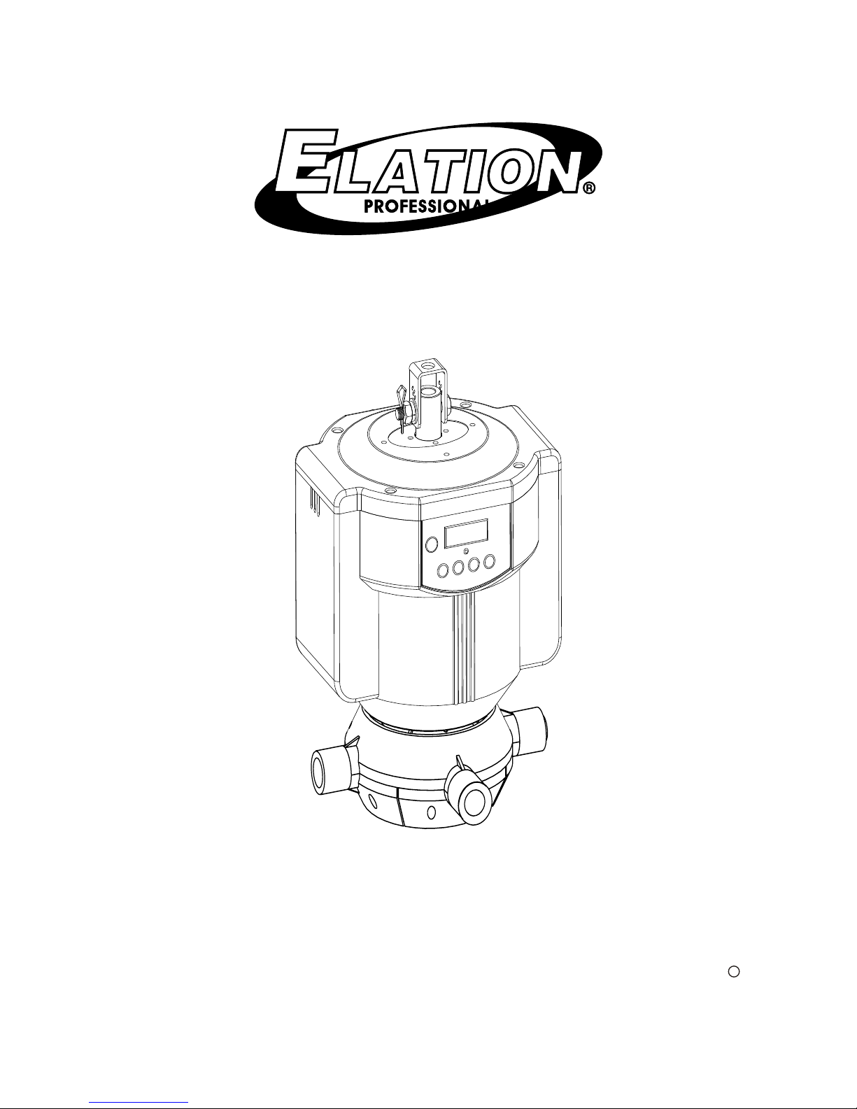
STREAMER
Users Instructions
Elation Professional
R
4295 Charter Street
Los Angeles CA. 90058
www.elationlighting.com
Page 2

-
-
-EEPROM for at least 10 years.
USITT DMX512(1990) multiplexed digital control, via 3 pin XLR connector.
-Light plastic material case(IP:V0).
-Slave, Auto and Audio function modes available.
-9 built-in chasing patterns plus a sequence of 9 patterns(AUTO).
-0~100(/0.1s) DMX fade time setup.
-Stand by function allows you to kill overall output instantly.
-Individual fibre lighting color adjustment and rotatable.
-4-digit Segment Display shows current activities or your desired levels.
At your most convenience, this unit can be entirely controlled except
DMX address setting by its Remote Control(Included).
Features
We would first like to congratulate you on the purchase of this
magic fibre lighting-STREAMER!
Its main features include:
Every effort has been made to design dependable and reliable products.
New products are constantly being designed to meet the needs of the
entertainment lighting industry. Your comments regarding our products
and services are welcome. Please send us an e-mail to
[email protected] and let us know how we can improve to better
serve you.
It is both a privilege and a pleasure serving you.
-Page1-
Every STREAMER has been thoroughly tested and has been shipped in perfect
operating condition. Carefully check the shipping carton for damage that may
have occurred during shipping. If the carton appears to be damaged, carefully
inspect your controller for any damage and be sure all equipment necessary to
operate the unit has arrived intact. In case damage has been found or parts are
missing, please contact us or your nearest dealer/distributor for further
instructions.
To make the most of it's possibilities and for a correct functioning of this unit
in years to come, we suggest all users to read carefully this manual before
connecting or putting the spot in use. By doing so, you will gain experience
with its commands and connections and you will be able to use it easily.
Once manual has been thoroughly read, we recommend you should file it for
future reference.
Caution! There are no user serviceable parts inside this unit. Do not attempt
any repairs yourself, doing so will void your manufactures warranty.
Hint! When unpacking and installation, make sure that your unit has been
taken out from the cylinder gently and placed properly by the correct directly.
In the unlikely event your unit may require service, please contact NCW
customer support.
Do not discard the packing carton in the trash. Please recycle when
ever possible.
General Information
NOTE:
Specifications and improvements in the design of this product and this
manual are subject to change without prior notice.
Page 3
Every STREAMER has been thoroughly tested and has been shipped in perfect
operating condition. Carefully check the shipping carton for damage that may
have occurred during shipping. If the carton appears to be damaged, carefully
inspect your controller for any damage and be sure all equipment necessary to
operate the unit has arrived intact. In case damage has been found or parts are
missing, please contact us or your nearest dealer/distributor for further
instructions.
To make the most of it's possibilities and for a correct functioning of this unit
in years to come, we suggest all users to read carefully this manual before
connecting or putting the spot in use. By doing so, you will gain experience
with its commands and connections and you will be able to use it easily.
Once manual has been thoroughly read, we recommend you should file it for
future reference.
Caution! There are no user serviceable parts inside this unit. Do not attempt
any repairs yourself, doing so will void your manufactures warranty.
Hint! When unpacking and installation, make sure that your unit has been
taken out from the cylinder gently and placed properly by the correct directly.
In the unlikely event your unit may require service, please contact NCW
customer support.
Do not discard the packing carton in the trash. Please recycle when
ever possible.
General Information
-Page2-
NOTE:
Specifications and improvements in the design of this product and this
manual are subject to change without prior notice.
Page 4
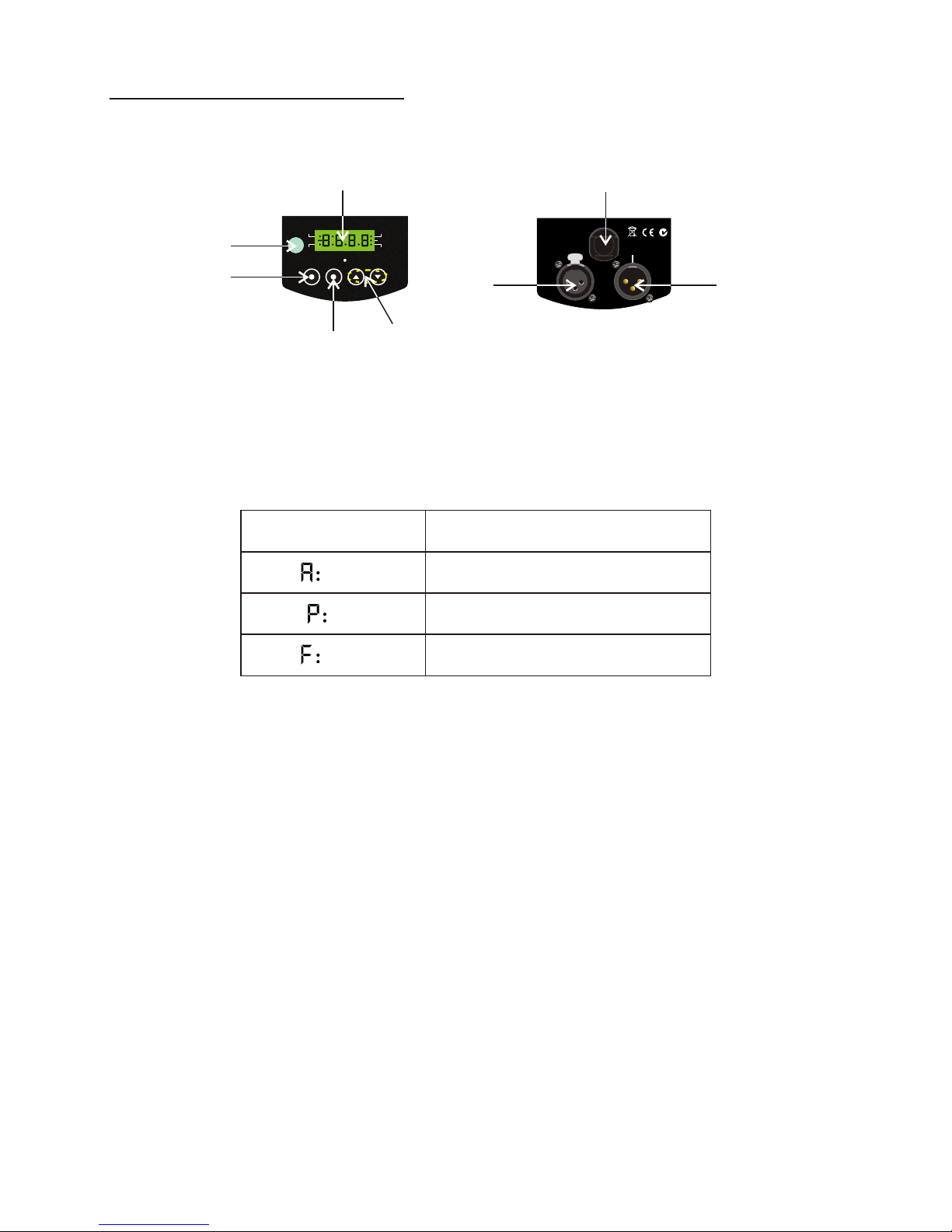
1. Digit Segment Display
The 4-digit LED display shows the menu and operating functions which users
can choose from. It also shows user desired levels including DMX address,
pattern numbers and fade time.
2. Infrared Sensor
To receive infrared remote signals.
3. Mode Button
Tap this button to select different function modes according to users
requirement including Slave, Auto and Audio modes.
4. Up/Down Button
Tap UP/DOWN button to select your desired DMX address, DMX fade time
or chasing patterns during operation.
5. Menu Button
Tap this button to enter the sub-menu in the Slave mode for user operation.
6. Power In
The line cord supplies power to the device. Plug into a AC90~264V-50/60Hz
outlet.
7. 3-pin XLR DMX Input Jack
This input receives DMX signal from a DMX controller or previous device.
8. 3-pin XLR DMX Output Jack
This output feeds DMX signal through to the next DMX device in line.
Related Info.
DMX Address(001-512)
Chasing patterns(1-9& Auto)
DMX Fade time(0-100)
XXX
XX
XXX
Segment Display
MODE
MENU UP
DOWN
STAND BY
DMX
SLAVE
AUDIO
AUTO
1
3
4
2
5
POWER IN:
AC 90-264V~
50/60Hz.
DMX INDMX OUT
PUSH
PUSH
PUSH
1
1
1
2
2
2
3
3
3
3
3
3
2
2
2
1
1
1
6
7
8
Front View Rear View
Controls & Functions
-Page3-
Unpacking Notice
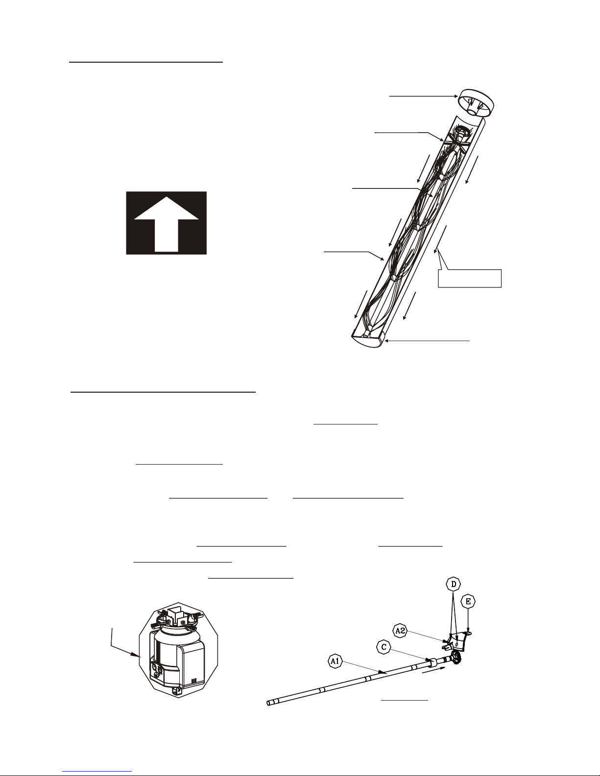
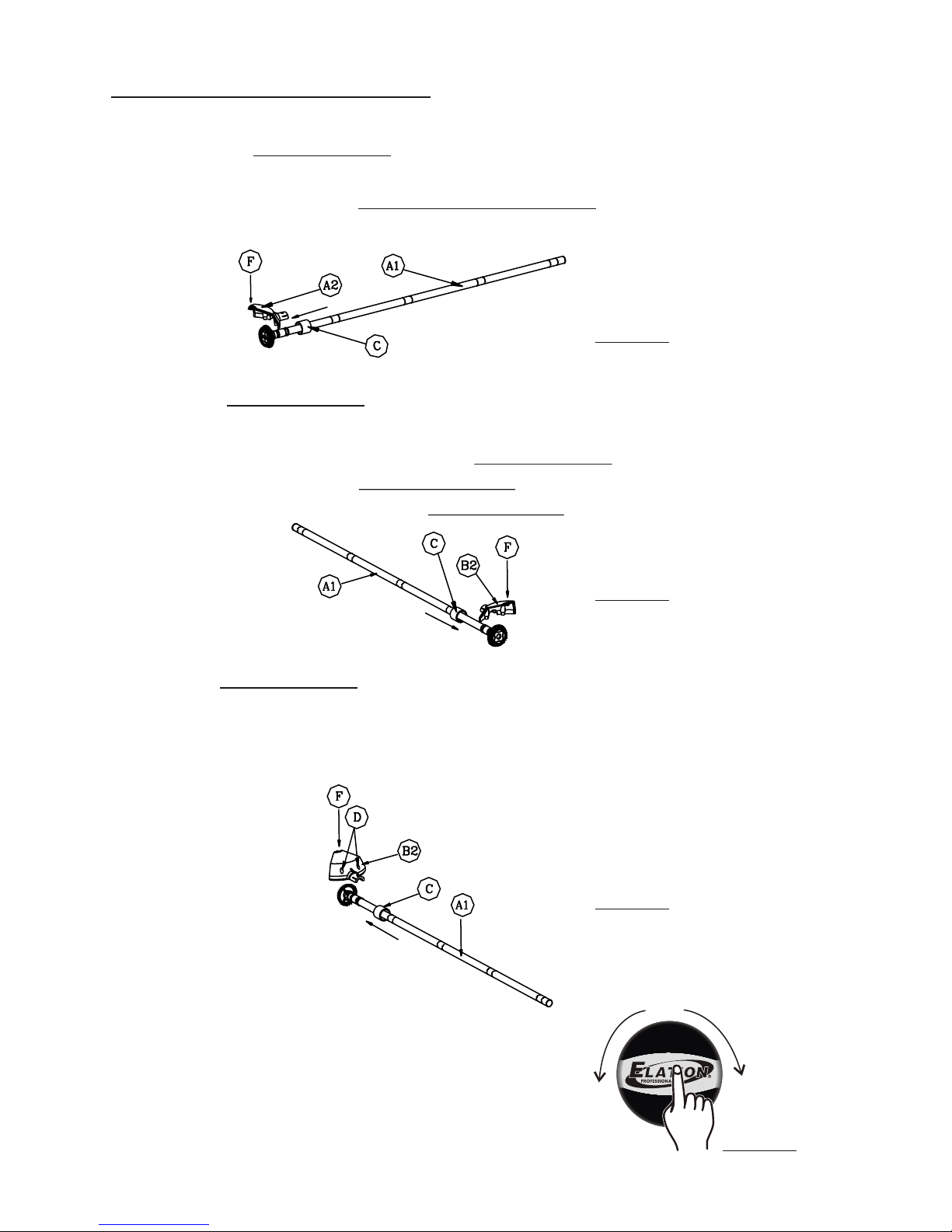
Before installation, please make sure that KIT ASM-A has been hanged fully
and safely.
Installation Procedures
Step1
Firstly assemble A2(Plastic cover)and E(Aluminum sheet) together with one
screw by the screwdriver.
Step2
Select any of these 4 Fibre tubes(A1) and place it on KIT ASM-A properly,
and install A2(Plastic cover) ,then screw them with two screws by the screwdriver,
at last fasten them with C(Plastic tube).
1. The first Fibre Tube(A1) Installation(See figure-2)
Unpack:
Remove the base cover and take out
the fiber tube from paper cylinder.
Page 5
Unpacking Notice
Before installation, please make sure that KIT ASM-A has been hanged fully
and safely.
KIT ASM-A
Installation Procedures
Step1
Firstly assemble A2(Plastic cover)and E(Aluminum sheet) together with one
screw by the screwdriver.
Step2
Select any of these 4 Fibre tubes(A1) and place it on KIT ASM-A properly,
and install A2(Plastic cover) ,then screw them with two screws by the screwdriver,
at last fasten them with C(Plastic tube).
(Figure-2)
1. The first Fibre Tube(A1) Installation(See figure-2)
Unpack:
Remove the base cover and take out
the fiber tube from paper cylinder.
TOP
-Page4-
be
u
bF
i r
t
e
C
y
l
i
der
n
B
a e
o e (
PV
C)
s
c v
r
Fx
St
a
d
i
n
Top covre(PVC)
Pull Out
Page 6
Installation Procedures
Step5
And repeat Step4 to install the last fibre tube. And please check and ensure
all screws have been secured tightly.
2. The second Fibre Tube(A1) Installation(See figure-3)
Step3
And repeat Step2 to install the second A1(Fibre tube) and fix them well.
3. The third Fibre Tube(A1) Installation(See figure-4)
(Figure-3)
Step4
In like matter, select any of the rest two Fibre Tube(A1) and place it on
KIT ASM-A well, assemble Plastic cover(B2) and screw with two screws by
the screwdriver, then fix them with C(Plastic tube).
(Figure-4)
4. The last Fibre Tube(A1) Installation(See figure-5)
(Figure-5)
Step6
Push a STICKER with "ELATION" printing into
the top and rotate it clockwise or anti-clockwise.
-Page5-
S
R
T
E
R
E
M
A
S
R
T
R
E
M
E
A
(Figure-6)
Operation Guide
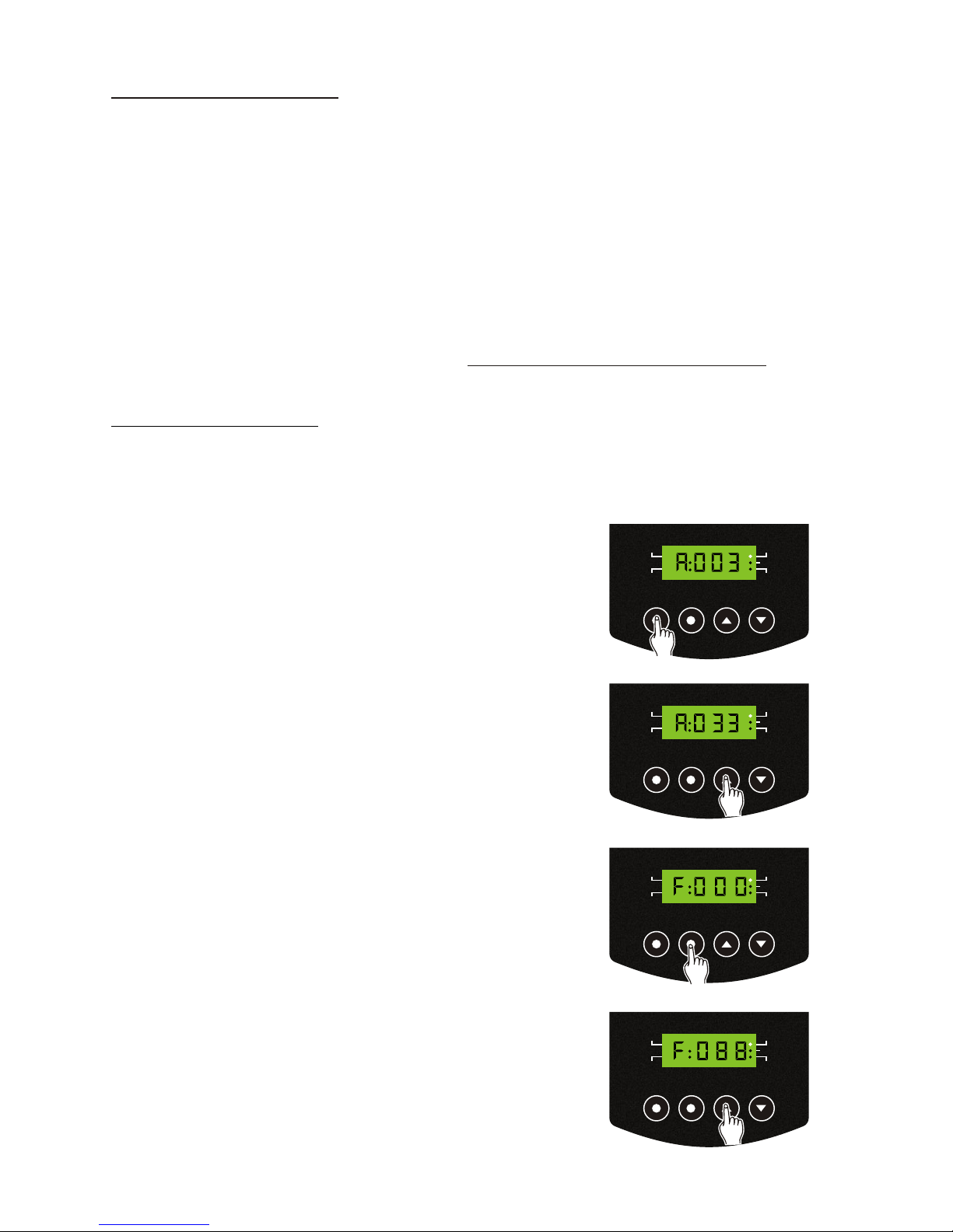
Slave 0 R G H
1. Press the Mode button to access the Slave
Mode, the readout of an "A" followed by
three numbers will be indicated and the
Slave indicator will be lit on the LED-display.
2. And use Up/Down button to select your
desired DMX address within the range of
1-512.
3. Press the Menu button to change between
DMX address and DMX fade time setting.
4. And use Up/Down button to select your
desired DMX fade time within the range
of 0-100(0.1s).
In this mode, users can have DMX address setting and DMX fade time , and
daisy chain up to some units together to get a sync lighting show.
' 0 ; & RQWURO
Channel 1 is the rotary speed for motor, channel 2 is the rotary direction for
motor (0~127 is to rotate clockwise and 128-255 is anticlockwise movement),
and Channel 3-6 is the color for the fibre lighting tube.
Please follow the set-up specifications( ) that
come with your DMX controller.
DMX Signal Indicator
When STREAMERs are receiving DMX signal for Master-Slave operation, its
DMX indicator on the screen will blink constantly.
Page 7
Operation Guide
Slave 0 R G H
-Page6-
1. Press the Mode button to access the Slave
Mode, the readout of an "A" followed by
three numbers will be indicated and the
Slave indicator will be lit on the LED-display.
MODE
MENU UP
DOWN
STAND BY
DMX
SLAVE
AUDIO
AUTO
2. And use Up/Down button to select your
desired DMX address within the range of
1-512.
MODE
MENU UP
DOWN
STAND BY
DMX
SLAVE
AUDIO
AUTO
3. Press the Menu button to change between
DMX address and DMX fade time setting.
4. And use Up/Down button to select your
desired DMX fade time within the range
of 0-100(0.1s).
MODE
MENU UP
DOWN
STAND BY
DMX
SLAVE
AUDIO
AUTO
MODE
MENU UP
DOWN
STAND BY
DMX
SLAVE
AUDIO
AUTO
In this mode, users can have DMX address setting and DMX fade time , and
daisy chain up to some units together to get a sync lighting show.
' 0 ; & RQWURO
Channel 1 is the rotary speed for motor, channel 2 is the rotary direction for
motor (0~127 is to rotate clockwise and 128-255 is anticlockwise movement),
and Channel 3-6 is the color for the fibre lighting tube.
Please follow the set-up specifications( ) that
come with your DMX controller.
RGB color and DMX value Table
DMX Signal Indicator
When STREAMERs are receiving DMX signal for Master-Slave operation, its
DMX indicator on the screen will blink constantly.
Page 8
-Page7-
Operation Guide
AUDIO0 R G H
1. Press the Mode button to access the AUDIO
mode indicator will be lit on the LED-display.
And your unit will run with the music beat.
MODE
MENU UP
DOWN
STAND BY
DMX
SLAVE
AUDIO
AUTO
7 K L V I X Q F WL R Q Z L OOD OOR Z \ R X WR OL Q N X S WR someX Q LWV WR J H WK H UWR UX Q LQ D 6 OD Y H
M RGH, Q0 DVWHU6 ODYHRSHUDWLRQ, R Q H X Q L WZ L OOserveD V WK H MasterDQGWKH
RWKHUVZ LOOserve as the Slave.HRZ HYHUthe only RQHXQLWcanrun in AUTO or
AUDIO mode and others run in Slave mode.
And only some STREAMERs with the same DMX signals can be connected
together for Master-Slave operation successfully. Or else, it can result out of
control.
Master-Slave Operation
Operation Guide
NOTE:
1. " N " denotes DMX value(0-255).
For example:
If DMX value is 239, blue intensity will be 50-(239-237)x6=38%,
red intensity will be 25-(239-237)x6=13%,
green intensity be 100%.
2. " * " denotes unnameable color.
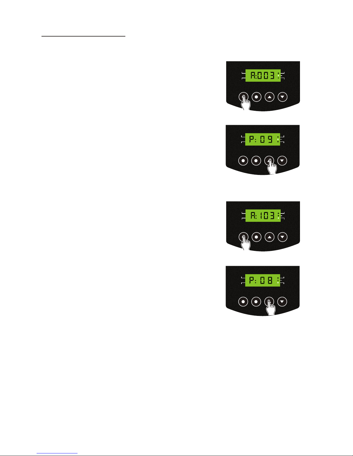
AUTO 0 R G H
1. Press the Mode button to access the AUTO
mode, the AUTO indicator will be lit on the
LED-display. And your unit patterns will run
automatically.
MODE
MENU UP
DOWN
STAND BY
DMX
SLAVE
AUDIO
AUTO
2. And use Up/Down button to select your
desired chasing patterns within the range
of 1-9 & AUTO.
MODE
MENU UP
DOWN
STAND BY
DMX
SLAVE
AUDIO
AUTO
2. And use Up/Down button to select your
desired chasing patterns within the range
of 1-9 & AUTO.
MODE
MENU UP
DOWN
STAND BY
DMX
SLAVE
AUDIO
AUTO
Page 9

Operation Guide
RGB color and DMX value Table
DMX (N)
(Decimal)
0
1-2
3-33
34
35-65
66-69
70-100
101
102-132
133-136
137-167
168
169-199
200-206
207
208-210
211
212-215
216-218
219-222
223-225
226-228
229
230-232
233
234-236
237
238-240
241-244
245-247
248-251
252-254
255
Blue
(%)
0
0
0
0
0
0
(N-69)x3
100
100
100
100
100
100-(N-168)x3
(N-199)x12
100
100
100
100-(N-211)x12
50-(N-215)x6
25-(N-219)x6
(N-219)x6
25+(N-225)x6
50
50+(N-229)x12
100
100
100
100
100
100
100
100
100
Red
(%)
0
100
100
100
100-(N-34)x3
0
0
0
0
0
(N-136)x3
100
100
100
100
100-(N-207)x12
50
50-(N-211)x6
50-(N-215)x6
(N-217)x6
38+(N-223)x6
50+(N-225)x12
100
100
100
100-(N-233)x12
50
50-(N-237)x6
25-(N-241)x6
(N-243)x6
25+(N-247)x6
50+(N-251)x12
100
Green
(%)
0
0
(N-2)x3
100
100
100
100
100
100-(N-101)x3
0
0
0
0
(N-199)x6
50
50+(N-207)x12
100
100
100
100
100
100
100
100-(N-229)x12
50
50-(N-233)x6
25
25-(N-237)x6
(N-239)x6
(N-239)x6
50+(N-247)x12
100
100
Color
Black
Red
***
Yellow
***
Green
***
Cyan
***
Blue
***
Purple
***
***
***
***
***
***
***
***
***
***
***
***
***
***
***
***
***
***
***
***
White
NOTE:
1. " N " denotes DMX value(0-255).
For example:
If DMX value is 239, blue intensity will be 50-(239-237)x6=38%,
red intensity will be 25-(239-237)x6=13%,
green intensity be 100%.
2. " * " denotes unnameable color.
-Page8-
Page 10
Operation Guide
-Page9-
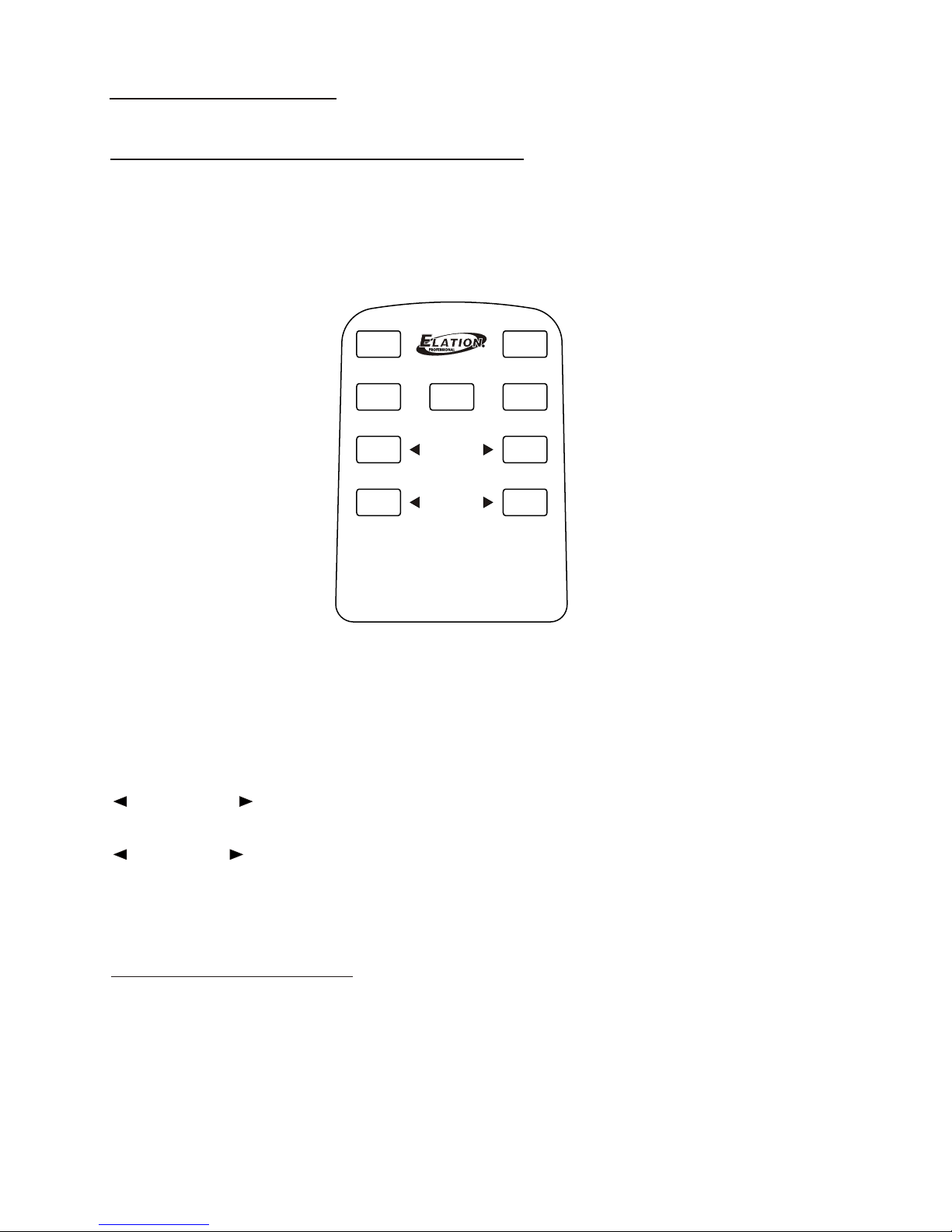
Using the Remote Control Properly
When using your Remote Control(included), please ensure to operate it
within the effective range of the infrared sensor, so that you may operate
your STREAMER at any safe place.
POWER ON key: To turn the power on.
STAND BY key: To allow you to kill overall output instantly.
DMX key: To access Slave Mode.
AUTO key: To access AUTO Mode.
AUDIO key: To access AUDIO Mode.
FADETIME key: To set up DMX fade time within the range of
0~100(/0.1s), only in Slave Mode .
PATTERN key: To select built-in chasing patterns within the range
of 1~9 plus AUTO, only in AUTO or AUDIO
Mode.
*Notes concerning use:
Periodically clean the Infrared receive sensor with a soft cloth. Do not expose
this unit to strong light, it may interfere with operation.
DMXDMX
AUTOAUTO
STAND BYSTAND BY
AUDIOAUDIO
FADETIMEFADETIME
PATTERNPA TTERN
POWER ONPOWER ON
STREAMERSTREAMER
Overview
Remote Control
Power Requirement...........................................................AC90~264V-50/60Hz
LED-display Screen.........................................................4-digit segment display
DMX In.............................................................................3-pin XLR male socket
DMX Out.......................................................................3-pin XLR female socket
Accessory....................................................................Remote Control(Included)
Weight..............................................................................................Appro.4.5Kg
Technical Specifications
Page 11

Power Requirement...........................................................AC90~264V-50/60Hz
LED-display Screen.........................................................4-digit segment display
DMX In.............................................................................3-pin XLR male socket
DMX Out.......................................................................3-pin XLR female socket
Accessory....................................................................Remote Control(Included)
Weight..............................................................................................Appro.4.5Kg
Technical Specifications
-Page10-
Page 12

A Division of the American DJ Group of Companies
4295 Charter Street Los Angeles, CA 90058 USA
Tel: 323-582-3322 Fax: 323-582-3311
Web: www.elationlighting.com
E-mail: [email protected]
Elation Professional
R
24-004-1843
Rev1.1
Page 13

Page 14

 Loading...