

Page 1
Color version
C/100 M/50 Y/50 K/50
C/98 M/88 Y/22 K/18
C/0 M/0 Y/0 K/0
Grayscale version
Black version
C/50 M/50 Y/50 K/100
C/50 M/50 Y/50 K/100
C/0 M/0 Y/0 K/0
KL Panel
User Manual
Page 2

©2021 ELATION PROFESSIONAL all rights reserved. Information, specifications,
Date
Document
Version
Software
Version ≥
DMX
Channel Modes
Notes
05/21/2020
1.0
1.01
1 / 4 / 5 / 7 / 10 / 13 / 20 CH
4 / 12 CH HSI
Initial release.
06/02/2020
1.1
1.01
No change.
Updated DMX functions.
06/16/2020
1.2
1.03
No change.
Updated System Menu.
10/20/2020
1.3
N/C
No change.
Updated specifications
12/18/2020
1.4
N/C
No Change
Updated Accessories List
01/26/2021
1.5
N/C
No Change
Added Battery Connection.
diagrams, images, and instructions herein are subject to change without notice. ELATION
PROFESSIONAL logo and identifying product names and numbers herein are trademarks
of ELATION PROFESSIONAL. Copyright protection claimed includes all forms and matters
of copyrightable materials and information now allowed by statutory or judicial law or
hereinafter granted. Product names used in this document may be trademarks or
registered trademarks of their respective companies and are hereby acknowledged. All
non-ELATION brands and product names are trademarks or registered trademarks of their
respective companies.
ELATION PROFESSIONAL and all affiliated companies hereby disclaim any and all
liabilities for property, equipment, building, and electrical damages, injuries to any persons,
and direct or indirect economic loss associated with the use or reliance of any information
contained within this document, and/or as a result of the improper, unsafe, insufficient and
negligent assembly, installation, rigging, and operation of this product.
Elation Professional USA | 6122 S. Eastern Ave. | Los Angeles, CA. 90040
323-582-3322 | 323-832-9142 fax | www.elationlighting.com | info@elationlighting.com
Elation Professional B.V. | Junostraat 2 | 6468 EW Kerkrade, The Netherlands
+31 45 546 85 66 | +31 45 546 85 96 fax | www.elationlighting.eu | info@elationlighting.eu
Elation Professional Mexico | AV Santa Ana 30 | Parque Industrial Lerma, Lerma, Mexico 52000
+52 (728) 282-7070
DOCUMENT VERSION
Due to additional product features and/or enhancements,
an updated version of this document may be available
online. Please scan the QR Code with your mobile device or
visit www.elationlighting.com for the latest revision/update of
this manual, before installation and/or programming.
2
Page 3

General Information
4
Limited Warranty (USA Only)
5
Safety Guidelines
6
Maintenance Guidelines
8
Fixture Overview
9
Installation Instructions
10
Battery Connection
16
System Menu
17
Manual Mode
18
DMX Channel Functions & Values
22
Dimmer Modes
36
CCT Tab le
37
Virtual Colors Table
38
Specifications
39
Dimensional Drawings
40
Optional Accessories
41
FCC Statement
42
CONTENTS
3
Page 4

GENERAL INFORMATION
INTRODUCTION
Please read and understand the instructions in this manual carefully and thoroughly before
attempting to operate this device. These instructions contain important safety and use information.
UNPACKING
Every device has been thoroughly tested and has been shipped in perfect operating condition.
Carefully check the shipping carton for damage that may have occurred during shipping. If the
carton is damaged, carefully inspect the device for damage, and be sure all accessories necessary
to install and operate the device have arrived intact. In the event damage has been found or parts
are missing, please contact our customer support team for further instructions. Please do not
return this device to your dealer without first contacting customer support. Please do not discard
the shipping carton in the trash. Please recycle whenever possible.
BOX CONTENTS
Diffuser
Barn Door Assembly
Junior Pin (1
Locking Power Cable
1
/8 in. – 28mm) with Mounting Hardware
CUSTOMER SUPPORT
Contact ELATION Service for any product related service and support needs.
Also visit forums.elationlighting.com with questions, comments or suggestions.
ELATION SERVICE USA - Monday - Friday 8:00am to 4:30pm PST
323-582-3322 | Fax 323-832-9142 | support@elationlighting.com
ELATION SERVICE EUROPE - Monday - Friday 08:30 to 17:00 CET
+31 45 546 85 63 | Fax +31 45 546 85 96 | support@elationlighting.eu
REPLACEMENT PARTS please visit parts.elationlighting.com
IMPORTANT NOTICE!
THERE ARE NO USER SERVICEABLE PARTS INSIDE THIS UNIT.
DO NOT ATTEMPT ANY REPAIRS YOURSELF; DOING SO WILL VOID YOUR
MANUFACTURER’S WARRANTY. DAMAGES RESULTING FROM MODIFICATIONS TO
THIS FIXTURE AND/OR THE DISREGARD OF SAFETY INSTRUCTIONS AND
GUIDELINES IN THIS MANUAL VOID THE MANUFACTURER’S WARRANTY AND ARE
NOT SUBJECT TO ANY WARRANTY CLAIMS AND/OR REPAIRS.
4
Page 5

LIMITED WARRANTY (USA ONLY)
A. Elation Professional hereby warrants, to the original purchaser, Elation Professional products to be free of
manufacturing defects in material and workmanship for a period of two years (730 days), and Elation Professional
product rechargeable batteries to be free of manufacturing defects in material and workmanship for a period of six
months (180 days), from the original date of purchase. This warranty excludes discharge lamps and all product
accessories. This warranty shall be valid only if the product is purchased within the United States of America,
including possessions and territories. It is the owner’s responsibility to establish the date and place of purchase by
acceptable evidence, at the time service is sought. B. For warranty service, send the product only to the Elation
Professional factory. All shipping charges must be pre-paid. If the requested repairs or service (including parts
replacement) are within the terms of this warranty, Elation Professional will pay return shipping charges only to a
designated point within the United States. If any product is sent, it must be shipped in its original package and
packaging material. No accessories should be shipped with the product. If any accessories are shipped with the
product, Elation Professional shall have no liability what so ever for loss and/or or damage to any such accessories,
nor for the safe return thereof. C. This warranty is void if the product serial number and/or labels are altered or
removed; if the product is modified in any manner which Elation Professional concludes, after inspection, affects the
reliability of the product; if the product has been repaired or serviced by anyone other than the Elation Professional
factory unless prior written authorization was issued to purchaser by Elation Professional; if the product is damaged
because not properly maintained as set forth in the product instructions, guidelines and/or user manual. D. This is not
a service contract, and this warranty does not include any maintenance, cleaning or periodic check-up. During the
periods as specified above, Elation Professional will replace defective parts at its expense, and will absorb all
expenses for warranty service and repair labor by reason of defects in material or workmanship. The sole
responsibility of Elation Professional under this warranty shall be limited to the repair of the product, or replacement
thereof, including parts, at the sole discretion of Elation Professional. All products covered by this warranty were
manufactured after January 1, 1990, and bare identifying marks to that effect. E. Elation Professional reserves the
right to make changes in design and/or performance improvements upon its products without any obligation to
include these changes in any products theretofore manufactured. F. No warranty, whether expressed or implied, is
given or made with respect to any accessory supplied with the products described above. Except to the extent
prohibited by applicable law, all implied warranties made by Elation Professional in connection with this product,
including warranties of merchantability or fitness, are limited in duration to the warranty periods set forth above. And
no warranties, whether expressed or implied, including warranties of merchantability or fitness, shall apply to this
product after said periods have expired. The consumer’s and/or dealer’s sole remedy shall be such repair or
replacement as is expressly provided above; and under no circumstances shall Elation Professional be liable for any
loss and/or damage, direct and/or consequential, arising out of the use of, and/or the inability to use, this product. G.
This warranty is the only written warranty applicable to Elation Professional products and supersedes all prior
warranties and written descriptions of warranty terms and conditions heretofore published.
WARRANTY RETURNS
All returned service items whether under warranty or not, must be freight pre-paid and accompany a return
authorization (R.A.) number. The R.A. number must be clearly written on the outside of the return package. A brief
description of the problem as well as the R.A. number must also be written down on a piece of paper and included
in the shipping container. If the unit is under warranty, you must provide a copy of your proof of purchase invoice.
Items returned without a R.A. number clearly marked on the outside of the package will be refused and returned at
customer’s expense. You may obtain a R.A. number by contacting customer support.
5
Page 6
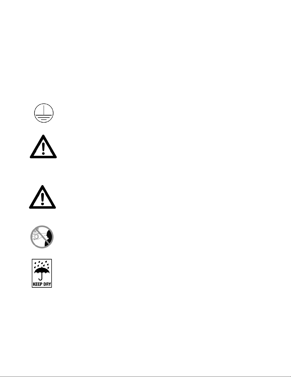
SAFETY GUIDELINES
PROTECTION CLASS 1 - FIXTURE MUST BE PROPERLY GROUNDED
THERE ARE NO USER SERVICEABLE PARTS INSIDE THIS UNIT.
DO NOT ATTEMPT ANY REPAIRS YOURSELF; DOING SO WILL VOID
YOUR MANUFACTURER’S WARRANTY. DAMAGES RESULTING
FROM MODIFICATIONS TO THIS FIXTURE AND/OR THE DISREGARD
OF SAFETY INSTRUCTIONS AND GUIDELINES IN THIS MANUAL
VOID THE MANUFACTURER’S WARRANTY AND ARE NOT SUBJECT
TO ANY WARRANTY CLAIMS AND/OR REPAIRS.
DO NOT PLUG FIXTURE INTO A DIMMER PACK!
NEVER OPEN THIS FIXTURE WHILE IN USE!
UNPLUG POWER BEFORE SERVICING FIXTURE!
NEVER TOUCH FIXTURE DURING OPERATION, AS IT MAY BE HOT!
KEEP FLAMMABLE MATERIALS AWAY FROM FIXTURE!
NEVER LOOK DIRECTLY INTO THE LIGHT SOURCE!
RETINA INJURY RISK - MAY INDUCE BLINDNESS!
SENSITIVE PERSONS MAY SUFFER AN EPILEPTIC SHOCK!
INDOOR / DRY LOCATIONS USE ONLY!
DO NOT EXPOSE FIXTURE TO RAIN AND MOISTURE!
This fixture is a sophisticated piece of electronic equipment. To guarantee smooth
operation, it is important to follow all instructions and guidelines in this manual. Elation
Professional is not responsible for injury and/or damages resulting from the misuse of this
fixture due to the disregard of the information printed in this manual. Only qualified and/or
certified personnel should perform installation of this fixture and only the original rigging
parts included with this fixture should be used for installation. Any modifications to the
fixture and/or the included mounting hardware will void the original manufactures warranty
and increase the risk of damage and/or personal injury.
6
Page 7

SAFETY GUIDELINES
DO NOT TOUCH the fixture housing during operation. Turn OFF the power and allow
approximately 15 minutes for the fixture to cool down before serving.
DO NOT shake fixture, and avoid brute force when installing and/or operating fixture.
DO NOT operate fixture if the power cord is frayed, crimped, damaged and/or if any of the
power cord connectors are damaged and do not insert into the fixture securely with ease.
NEVER force a power cord connector into the fixture. If the power cord or any of its
connectors are damaged, replace it immediately with a new one of similar power rating.
DO NOT block any air ventilation slots.
All fan and air inlets must remain clean and never blocked.
Allow approx. 6” (15cm) between fixture and other devices or a wall for proper cooling.
When installing fixture in a suspended environment, always use mounting hardware that is no
less than M10 x 25 mm, and always install fixture with an appropriately rated safety cable.
Always disconnect fixture from main power source before performing any type of service
and/or cleaning procedure. Only handle the power cord by the plug end, never pull out the
plug by tugging the wire portion of the cord.
During the initial operation of this fixture, a light smoke or smell may emit from the interior of
the fixture. This is a normal process and is caused by excess paint in the interior of the
casing burning off from the heat associated with the lamp and will decrease gradually over
time.
Consistent operational breaks will ensure fixture will function properly for many years.
ONLY use the original packaging and materials to transport the fixture for service.
7
Page 8

MAINTENANCE GUIDELINES
DISCONNECT POWER BEFORE PERFORMING ANY MAINTENANCE!
CLEANING
Frequent cleaning is recommended to insure proper function, optimized light output, and
an extended life. The frequency of cleaning depends on the environment in which the
fixture operates: damp, smoky or particularly dirty environments can cause greater
accumulation of dirt on the fixture’s optics. Clean the external lens surface periodically
with a soft cloth to avoid dirt/debris accumulation.
NEVER use alcohol, solvents, or ammonia-based cleaners.
MAINTENANCE
Regular inspections are recommended to ensure proper function and extended life.
There are no user serviceable parts inside this fixture, please refer all other service issues
to an authorized Elation service technician. Should you need any spare parts, please order
genuine parts from your local Elation dealer.
Please refer to the following points during routine inspections:
- A detailed electrical check by an approved electrical engineer every three months, to make sure the
circuit contacts are in good condition in order to prevent overheating.
- Be sure all screws and fasteners are securely tightened at all times. Loose screws may fall out during
normal operation, resulting in damage or injury as larger parts could fall.
- Check for any deformations on the housing, color lenses, rigging hardware and rigging points
(ceiling, suspension, trussing). Deformations in the housing could allow for dust to enter into the
fixture. Damaged rigging points or unsecured rigging could cause the fixture to fall and seriously
injure a person(s).
- Electric power supply cables must not show any damage, material fatigue, or sediments.
NEVER remove the ground prong from the power cable.
8
Page 9
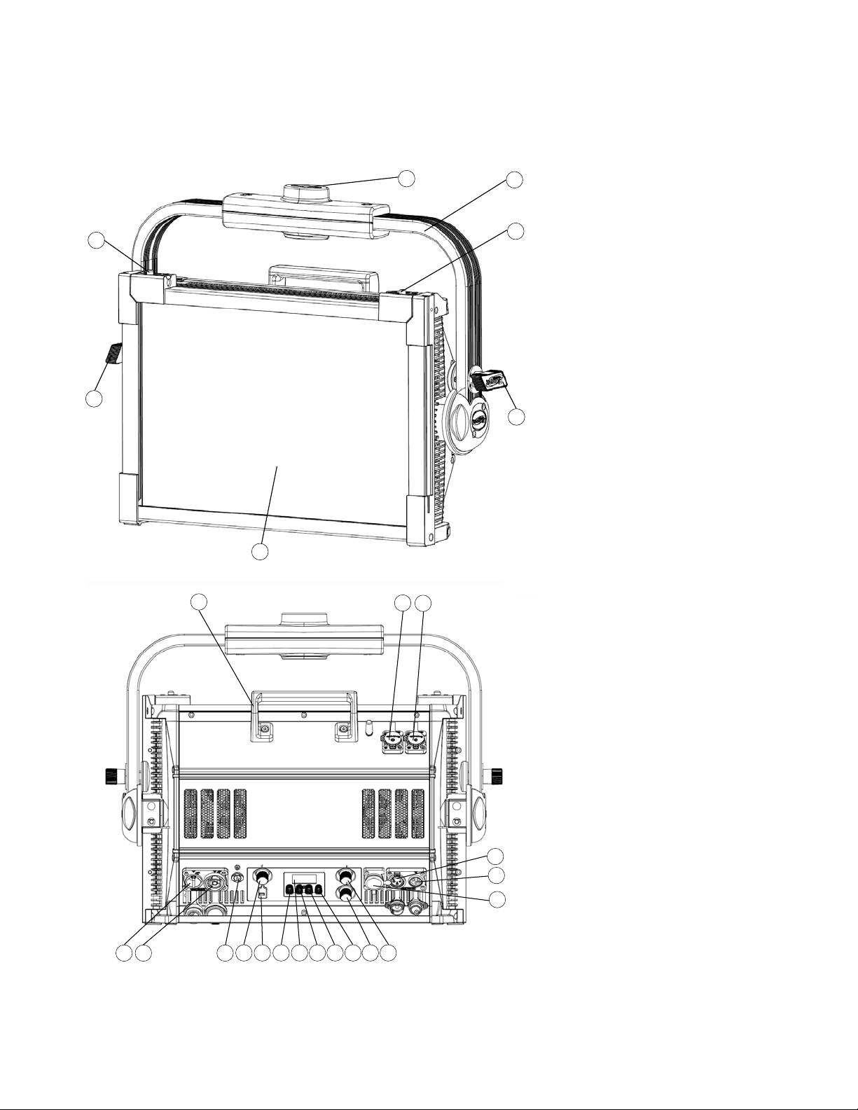
FIXTURE OVERVIEW
1
2
2
3
4
5
5
1. Removable Diffuser
2. Yo ke Adj ust men t Kn o b
3. Mounting Yoke
4. Clamp Mounting Point
5. Diffuser Frame Lock Tab
6. Carry Handle
7. Network In Connection
8. Network Out Connection
9. Power In Connection
10. Power Out Connection
11. Fuse – T6.3A / 250V
12. Encoder Knob 1
13. Service Port
14. Mode Button
15. Display Screen
16. Down Button
17. Up Button
18. Enter Button
19. Encoder Knob 3
20. Encoder Knob 2
21. DMX Out Connection
22. DMX In Connection
23. Battery Port
6
7 8
9 10
11
12 13 14 15 16 17 18 19 20
21
22
23
9
Page 10
INSTALLATION INSTRUCTIONS
FLAMMABLE MATERIAL WARNING
Keep fixture minimum 5.0 feet (1.5m) away from flammable materials and/or pyrotechnics.
ELECTRICAL CONNECTIONS
A qualified electrician should be used for all electrical connections and/or installations.
USE CAUTION WHEN POWER LINKING OTHER MODEL FIXTURES AS THE
POWER CONSUMPTION OF OTHER MODEL FIXTURES MAY EXCEED THE MAX
POWER OUTPUT ON THIS FIXTURE. CHECK SILK SCREEN FOR MAX AMPS.
DO NOT INSTALL THE FIXTURE IF YOU ARE NOT QUALIFIED TO DO SO!
Fixture MUST be installed following all local, national, and country commercial electrical
and construction codes and regulations.
Before rigging/mounting a single fixture or multiple interconnected fixtures for custom
matrix designs to any metal truss/structure or placing the fixture(s) on any surface, a
professional equipment installer MUST be consulted to determine if the metal
truss/structure or surface is properly certified to safely hold the combined weight of the
fixture(s), clamps, cables, and accessories.
Maximum fixture ambient operating temperature is 113°F (45°C).
Do not operate this fixture when ambient temperature exceeds this rating.
Fixture(s) should be installed in areas outside walking paths, seating areas, or away from
areas were unauthorized personnel might reach the fixture by hand.
NEVER stand directly below the fixture(s) when rigging, removing or servicing.
Overhead fixture installation must always be secured with a secondary safety attachment,
such as an appropriately rated safety cable that meets all local, national, and country
codes and regulations. Allow approximately 15 minutes for the fixture to cool down before
serving.
10
Page 11
INSTALLATION INSTRUCTIONS
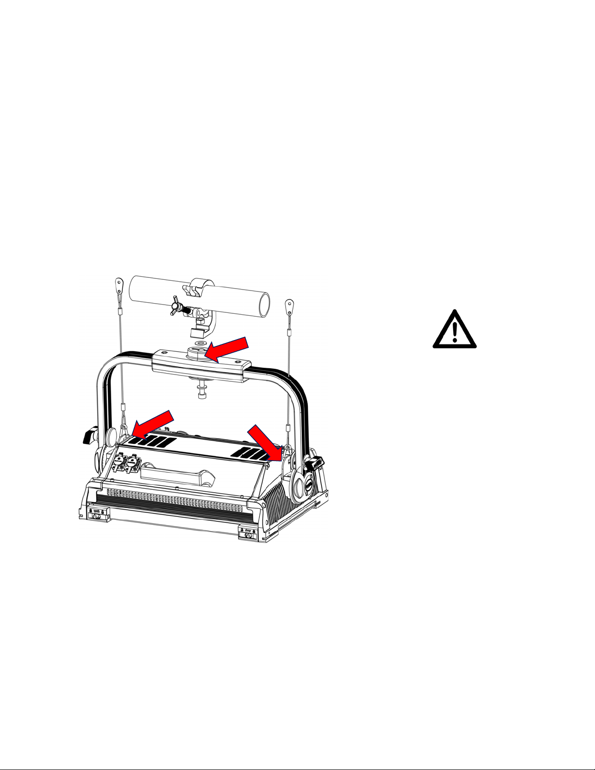
Safety Cable Rigging
Points (2)
Clamp Mounting Point
SAFETY CABLE
ALWAYS ATTACH A SAFETY CABLE
WHENEVER INSTALLING THIS
FIXTURE IN A SUSPENDED
ENVIRONMENT TO ENSURE THE
FIXTURE WILL NOT DROP IF THE
CLAMP FAILS.
CLAMP INSTALLATION
This fixture includes an adjustable mounting yoke with an integrated clamp mounting
point, as well as two (2) safety cable rigging points attached to the body of the fixture (see
the illustration below). When mounting this fixture to truss, be sure to secure an
appropriately rated clamp (not included) to the clamp mounting point on the yoke and
attach a separate SAFETY CABLE of the appropriate rating to each safety cable rigging
point on the fixture.
RIGGING
Overhead rigging requires extensive experience, including amongst others calculating
working load limits, understanding the installation material being used, and periodic safety
inspection of all installation material and the fixture. If you lack these qualifications, do not
attempt the installation yourself. Improper installation can result in bodily injury.
11
Page 12
INSTALLATION INSTRUCTIONS
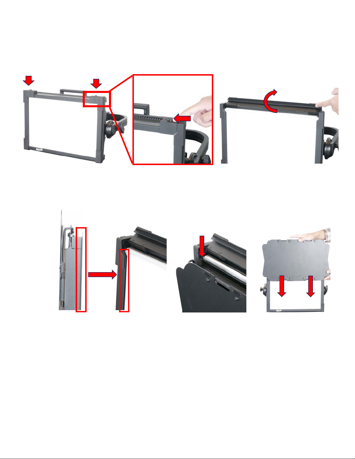
FRONT
BARN DOOR
1. Unlock both diffuser frame lock tabs using the latches located on each tab. Flip the top edge of
the frame upward.
2. The inner frame of the fixture contains an empty mounting slot located just in front of the
removable diffuser. Align the mounting rail on the rear of the barn door with this empty mounting
slot, and slowly lower the barn door into place.
12
Page 13
INSTALLATION INSTRUCTIONS
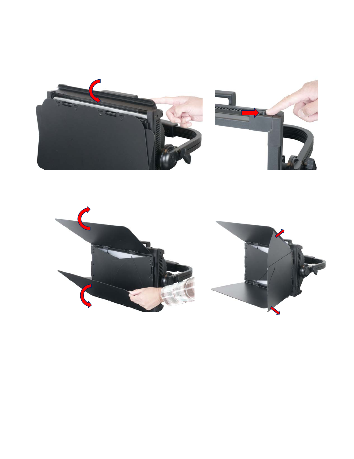
BARN DOOR
3. Flip the top edge of the frame downwards, and engage the lock tabs.
4. Flip the four (4) barn door segments outward. Note that the left and right barn door segments can
be expanded by pulling upwards or downwards on the thumb tabs.
13
Page 14
INSTALLATION INSTRUCTIONS
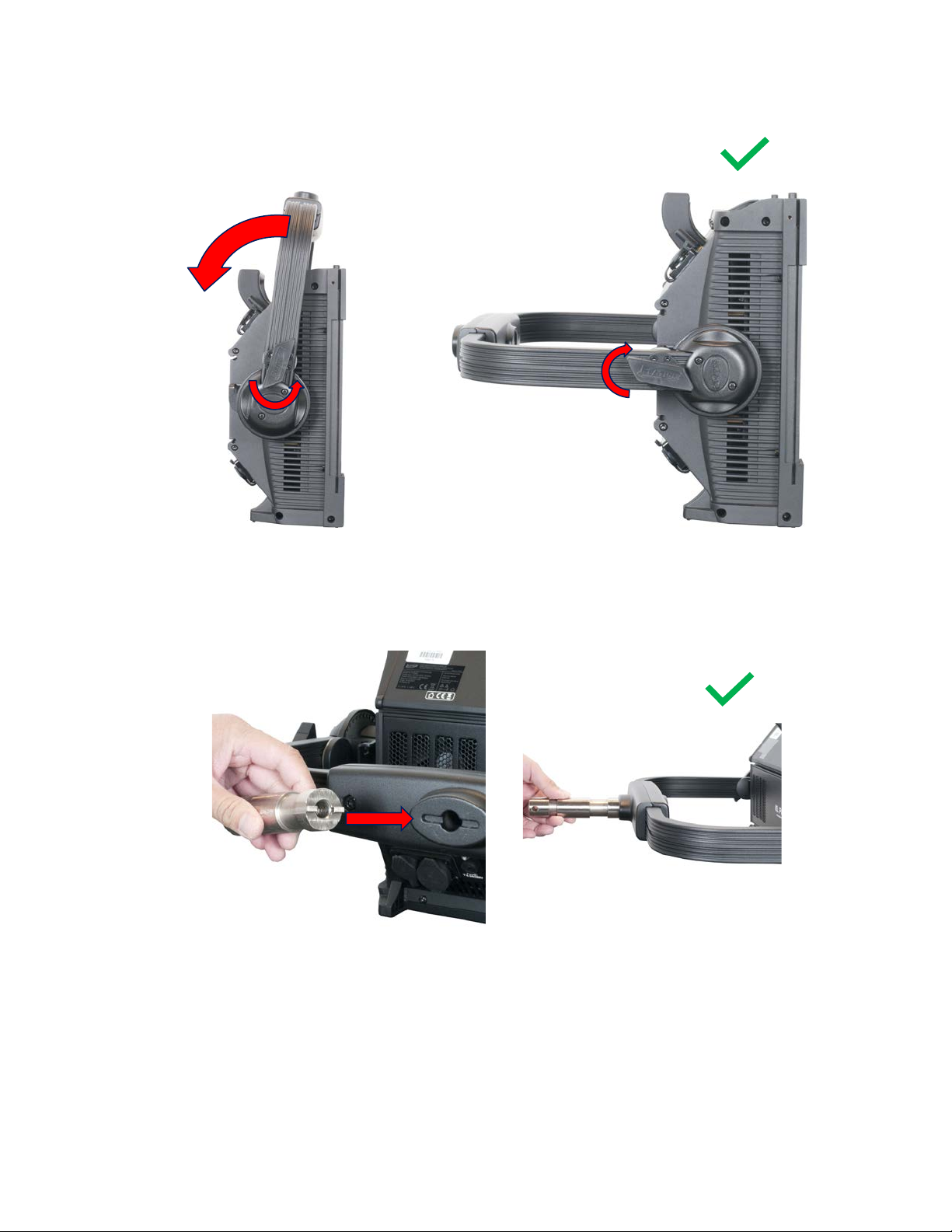
JUNIOR PIN
1. Loosen the yoke adjustment knobs, and adjust the mounting yoke to a position that allows access
to both the top and bottom sides of the yoke. Re-tighten the yoke adjustment knobs to lock the
yoke in position.
2. Locate the notched face of the junior pin, and hold it against the clamp mounting point located
on the top side of the yoke. The notched surface of the junior pin must sit flush against the
matching groove on the surface of the clamp mounting point.
14
Page 15

INSTALLATION INSTRUCTIONS
JUNIOR PIN
3. Thread the junior pin bolt in through the under side of the mounting yoke, making sure that the
bolt engages the threaded hole in the junior pin. Tighten securely with a 10mm hex key. The junior
pin is now ready for attachment to a clamp or stand.
15
Page 16

BATTERY CONNECTION
The KL Panel is capable of receiving power from a battery pack.
NOTICE: The user is responsible for ensuring compatibility between the device and the
battery pack. Always ensure that the output specifications, operating conditions, and
connection pinouts of the battery pack match the device requirements.
The device features a 4-pin XLR connector for battery power. The connector is located on
the back of the device, next to the DMX In/Out connectors, and is covered with a dust cap.
BE CAREFUL NOT TO CONNECT BATTERY POWER TO ONE OF THE DMX
CONNECTORS BY MISTAKE!
The pinout is illustrated below:
Consult the Safety Guidelines section of this user manual, as well as any safety
instructions included with your battery pack, before use or installation.
The KL Panel consumes 300W when operating all LEDs at full output, which may require
significant battery output to provide the required power. To extend the battery life, it is
possible to reduce the LED power down to 50% of maximum output using the “LED Power
Limit” menu in the Personality section of the system menu. Please refer to the System
Menu section of this manual for detailed information.
16
Page 17

SYSTEM MENU
The fixture includes an easy to navigate system menu. The control panel (see image below)
located on the back of the fixture provides access to the main system menu, where all
necessary system adjustments are made. During normal operation, pressing MODE button
once will access the fixture’s main menu. Once in the main menu you can navigate through
the different functions and access the sub-menus with the UP and DOWN buttons. Once
you reach a field that requires adjusting, press the ENTER button to activate that field and
use the UP and DOWN buttons to adjust the field. Pressing the ENTER button once more
will confirm your setting. You may exit the main menu at any time without making any
adjustments by pressing the MODE button.
The display screen can be locked by selecting PERSONALITY à DISPLAY à SCREEN
LOCK. To unlock the display screen, simply press and hold the MODE button for three (3)
seconds.
17
Page 18

SYSTEM MENU
Elation KL Panel System Menu
Supports Software Versions: 1.03
MANUAL MODE
Disabled
See Manual Mode
section for details
Int CCT Grn
HSI Int Color Sat
Manual Control
DMX SETTINGS
DMX Address
001 – 512
DMX Mode
1-CH Dimmer
4-CH Dimmer Color
7-CH Dimmer Color FX
6-CH RGBWLC
12-CH RGBWLC 16-Bit
14-CH Standard
23-CH Extended
4-CH HSI
12-CH HSI Extended
No DMX Status
Hold Last
Fade to Black
Standalone
STANDALONE
Dimmer
0 – 100%
CCT
2000 – 10000K
Green Shift
-100% ~ +100%
Virtual Color
Color01
See Color Table
Color02
…
Color60
PERSONALITY
Master
On / Off
Slave
On / Off
Select Signal
DMX or E-Fly
E-Fly and DMX Out
Dim Mode
Standard
Stage
TV Architectural
Theatre
Stage2
Dim Speed (0.0s ~ 10.0s)
Dim Curves
Linear
Square
Square Inverse
S-Curve
E-Fly Setting
Set Channel
00 – 14
Enable E-Fly
Yes / No
CONTINUED ON NEXT PAGE
18
Page 19

PERSONALITY
(continued from prev
page)
LED Refresh Rate
900 – 1500 Hz
2500 Hz
4000 Hz
5000 Hz
6000 Hz
10 KHz
15 KHz
20 KHz
25 KHz
LED Power Limit
50%
60%
70%
80%
90%
100%
Fan Mode
Auto
Silent
High
Display
Screen Delay
3 – 10s
Screen Lock
Note: To unlock screen,
press and hold MODE
button for 3 seconds.
Rotate Display 180°
Yes / No / Auto
Network
Switch
On / Off
Univers
0 – 255
IP Subnet
Protocol
ArtNet / KlingNet
Service (Passcode: 050)
Calibration
Red: 50 – 255
Green: 50 – 255
Blue: 50 – 255
Lime: 50 – 255
White: 50 – 255
Cyan: 50 – 255
Update Software
Yes / No
Factory Restore
Yes / No
Edit RDIM UID
INFORMATION
Life Time
Last Run Time
Time Reset (Passcode: 038)
Temperatures
Current
Max Resettable
Max Unresettable
Reset (Passcode: 038)
DMX Values
Product ID’s
Mac Address
RDM UID
Error Logs
Fixture Errors
Reset Error Log (Passcode:
050)
Yes / No
Software Version
19
Page 20

MANUAL MODE
Elation KL Panel Manual Mode
Supports Software Versions: 1.03
Encoder
Knob
Parameter
Display
Resolution/ Steps
Default
1
Intensity
Intensity 0-100%
1%
0%
2
Color Temperature
CCT 2000 – 10000K
100K
6000K
3
Green Shift
GRN -100% to +100%
1%
Neutral
Elation KL Panel Manual Mode
Supports Software Versions: 1.03
Encoder
Knob
Parameter
Display
Resolution/ Steps
Default
1
Intensity
Intensity 0-100%
1%
0%
2
Hue
Hue 0 – 360°
1°
0° 3 Saturation
Sat 0 – 100%
1%
100%
ENCODER KNOB DESIGNATIONS
INT CCT GRN (INTENSITY, COLOR TEMPERATURE, GREEN SHIFT)
HSI (HUE, SATURATION, INTENSITY)
20
Page 21

MANUAL MODE
Elation KL Panel Manual Mode
Supports Software Versions: 1.03
Encoder
Knob
Parameter
Display
Resolution/ Steps
Default
1
Intensity
Intensity 0-100%
1%
0%
2
Color
White, Virtual Color 1, 2, 3, 4…
Single Color
White
3
Saturation
Sat 0 – 100%
1%
100%
Elation KL Panel Manual Mode
Supports Software Versions: 1.03
Encoder
Knob
Parameter
Display
Resolution/ Steps
Default
1
Intensity
Intensity 0-100%
1%
0%
2
Setting Adjustment
[Setting Name] 0 – 255
1
0
3
Setting Selection
[Setting Name] 0 – 255
Strobe / Red /
Green / Blue /
White / Lime/ Cyan
Strobe
INT COL SAT (INTENSITY, COLOR, SATURATION)
MANUAL
21
Page 22

DMX CHANNEL FUNCTIONS AND VALUES
Elation KL Panel DMX Channels / Functions
Supports Software Versions: 1.03
Channel
Value
Function
Default
Snap 1 0 – 255
Dimmer Intensity, 0 to 100%
0
Elation KL Panel DMX Channels / Functions
Supports Software Versions: 1.03
Channel
Value
Function
Default
Snap 1 0 – 255
Dimmer Intensity, 0 to 100%
0 2
0 – 255
Dimmer Fine
0
3
CCT
0
0 – 19
Open
20 – 100
CCT 2000K – 10000K (see CCT Table)
101 – 255
10000K 4 Color Wheel
0
0
Open
1 – 179
Virtual Swatch Book (see Virtual Colors Table)
Color Scroll
180 – 201
Clockwise, Fast to Slow
202 – 207
Stop
208 – 229
Counter-clockwise, Slow to Fast
230 – 234
Open
Random Color Scroll
235 – 239
Fast
240 – 244
Medium
245 – 249
Slow
250 – 255
Open
1-CH DIMMER MODE
4-CH DIMMER COLOR MODE
22
Page 23

7-CH DIMMER COLOR FX MODE
Elation KL Panel DMX Channels / Functions
Supports Software Versions: 1.03
Channel
Value
Function
Default
Snap 1 0 – 255
Dimmer Intensity, 0 to 100%
0 2
0 – 255
Dimmer Fine
0
3
CCT
0
0 – 19
Open
20 – 100
CCT 2000K – 10000K (see CCT Table)
101 – 255
10000K 4 Color Wheel
0
0
Open
1 – 179
Virtual Swatch Book (see Virtual Colors Table)
Color Scroll
180 – 201
Clockwise, Fast to Slow
202 – 207
Stop
208 – 229
Counter-clockwise, Slow to Fast
230 – 234
Open
Random Color Scroll
235 – 239
Fast
240 – 244
Medium
245 – 249
Slow
250 – 255
Open
5
0 – 255
FX Selection*
0
Snap 6 0 – 255
FX Adjustment
127
Fade
7
FX Offset
0
Snap
0
Idle
1
Fixture Offset, 10°
2
Fixture Offset, 20°
… … 35
Fixture Offset, 350°
36
Synchronized
37 – 100
No Function
101 – 120
Random Fixture Offset
121 – 140
Random Pixel Order
141 – 255
Random Steps
Elation KL Panel DMX Channels / Functions
Supports Software Versions: 1.03
Channel
Value
Function
Default
Snap 1 0 – 255
Red, 0 to 100%
0 2
0 – 255
Green, 0 to 100%
0 3
0 – 255
Blue, 0 to 100%
0 4
0 – 255
White, 0 to 100%
0 5
0 – 255
Lime, 0 to 100%
0 6
0 – 255
Cyan, 0 to 100%
0
*Internal FX currently are not implemented.
6-CH RGBWLC MODE
23
Page 24

12-CH RGBWLC 16-BIT MODE
Elation KL Panel DMX Channels / Functions
Supports Software Versions: 1.03
Channel
Value
Function
Default
Snap 1 0 – 255
Red, 0 to 100%
0 2
0 – 255
Red Fine, 0 to 100%
0 3
0 – 255
Green, 0 to 100%
0 4
0 – 255
Green Fine, 0 to 100%
0 5
0 – 255
Blue, 0 to 100%
0 6
0 – 255
Blue Fine, 0 to 100%
0 7
0 – 255
White, 0 to 100%
0 8
0 – 255
White Fine, 0 to 100%
0 9
0 – 255
Lime, 0 to 100%
0 10
0 – 255
Lime Fine, 0 to 100%
0 11
0 – 255
Cyan, 0 to 100%
0 12
0 – 255
Cyan Fine, 0 to 100%
0
Elation KL Panel DMX Channels / Functions
Supports Software Versions: 1.03
Channel
Value
Function
Default
Snap
1
Strobe
50
Snap
0 – 31
Shutter Closed
32 – 63
No Function (Shutter Open)
64 – 95
Strobe Effect, Slow to Fast
96 – 127
No Function (Shutter Open)
128 – 159
Pulse Effect in Sequences
160 – 191
No Function (Shutter Open)
192 – 223
Random Strobe Effect, Slow to Fast
224 – 255
No Function (Shutter Open)
2
0 – 255
Dimmer Intensity, 0 to 100%
0 3
0 – 255
Dimmer Fine
0 4
0 – 255
Red, 0 to 100%
0 5
0 – 255
Green, 0 to 100%
0 6
0 – 255
Blue, 0 to 100%
0
7
CCT
0
0 – 19
Open
20 – 100
CCT 2000K – 10000K (see CCT Table)
101 – 255
10000K 8 Green Shift
0
0
Idle
1 – 127
Full Minus Green to Neutral
128
Neutral White
129 – 255
Neutral to Full Plus Green
CONTINUED ON NEXT PAGE
14-CH STANDARD MODE
24
Page 25

Channel
Value
Function
Default
Snap
9
Color Wheel
0
0
Open
1 – 179
Virtual Swatch Book (see Virtual Colors Table)
Color Scroll
180 – 201
Clockwise, Fast to Slow
202 – 207
Stop
208 – 229
Counter-clockwise, Slow to Fast
230 – 234
Open
Random Color Scroll
235 – 239
Fast
240 – 244
Medium
245 – 249
Slow
250 – 255
Open
10
Dim Modes
0
Snap
0 – 20
Standard
21 – 40
Stage
41 – 60
TV
61 – 80
Architectural
81 – 100
Theatre
101 – 120
Stage 2
Dimmer Display Time
121
0 s
122
0.1 s
123
0.2 s
124
0.3 s
125
0.4 s
126
0.5 s
127
0.6 s
128
0.7 s
129
0.8 s
130
0.9 s
131
1.0 s
132
1.5 s
133
2.0 s
134
3.0 s
135
4.0 s
136
5.0 s
137
6.0 s
138
7.0 s
139
8.0 s
140
9.0 s
141
10.0 s
142 – 255
Idle
11
Control
0
Snap
0 – 29
Idle
30 – 39
Fan Mode Auto
40 – 49
Fan Mode Silent
50 – 59
Fan Mode High
60 – 79
Idle
80 – 84
Reset
85 – 99
Idle
CONTINUED ON NEXT PAGE
25
Page 26

Channel
Value
Function
Default
Snap
11
(continued
from prev
page)
Refresh Rate
0
Snap
100
900 Hz
101
910 Hz
102
920 Hz
103
930 Hz
104
940 Hz
105
950 Hz
106
960 Hz
107
970 Hz
108
980 Hz
109
990 Hz
110
1000 Hz
111
1010 Hz
112
1020 Hz
113
1030 Hz
114
1040 Hz
115
1050 Hz
116
1060 Hz
117
1070 Hz
118
1080 Hz
119
1090 Hz
120
1100 Hz
121
1110 Hz
122
1120 Hz
123
1130 Hz
124
1140 Hz
125
1150 Hz
126
1160 Hz
127
1170 Hz
128
1180 Hz
129
1190 Hz
130
1200 Hz
131
1210 Hz
132
1220 Hz
133
1230 Hz
134
1240 Hz
135
1250 Hz
136
1260 Hz
137
1270 Hz
138
1280 Hz
139
1290 Hz
140
1300 Hz
141
1310 Hz
142
1320 Hz
143
1330 Hz
144
1340 Hz
145
1350 Hz
146
1360 Hz
147
1370 Hz
148
1380 Hz
149
1390 Hz
CONTINUED ON NEXT PAGE
26
Page 27

Channel
Value
Function
Default
Snap
11
(continued
from prev
page)
Refresh Rate (continued from prev page)
0
Snap
150
1400 Hz
151
1410 Hz
152
1420 Hz
153
1430 Hz
154
1440 Hz
155
1450 Hz
156
1460 Hz
157
1470 Hz
158
1480 Hz
159
1490 Hz
160
1500 Hz
161
2500 Hz
162
4000 Hz
163
5000 Hz
164
6000 Hz
165
10000 Hz
166
15000 Hz
167
20000 Hz
168
25000 Hz
169 – 200
Idle
201 – 210
Dimmer Curve Linear (default)
211 – 220
Dimmer Curve Square
221 – 230
Dimmer Curve Inverse Square
231 – 240
Dimmer Curve S-Curve
241
Internal Program 1 (Scene 1 – 8)
242
Internal Program 2 (Scene 9 – 16)
243
Internal Program 3 (Scene 17 – 24)
244
Internal Program 4 (Scene 25 – 32)
245
Internal Program 5 (Scene 33 – 40)
246
Internal Program 6 (Scene 41 – 48)
247
Internal Program 7 (Scene 49 – 56)
248 – 255
Idle
12
0 – 255
FX Selection*
0
Snap
13
0 – 255
FX Adjustment
127
Fade
14
FX Offset
0
Snap
0
Idle
1
Fixture Offset, 10°
2
Fixture Offset, 20°
… … 35
Fixture Offset, 350°
36
Synchronized
37 – 100
No Function
101 – 120
Random Fixture Offset
121 – 140
Random Pixel Order
141 – 255
Random Steps
*Internal FX currently are not implemented.
27
Page 28

23-CH EXTENDED MODE
Elation KL Panel DMX Channels / Functions
Supports Software Versions: 1.03
Channel
Value
Function
Default
Snap
1
Strobe
50
Snap
0 – 31
Shutter Closed
32 – 63
No Function (Shutter Open)
64 – 95
Strobe Effect, Slow to Fast
96 – 127
No Function (Shutter Open)
128 – 159
Pulse Effect in Sequences
160 – 191
No Function (Shutter Open)
192 – 223
Random Strobe Effect, Slow to Fast
224 – 255
No Function (Shutter Open)
2
0 – 255
Dimmer Intensity, 0 to 100%
0 3
0 – 255
Dimmer Fine
0 4
0 – 255
Red, 0 to 100%
0 5
0 – 255
Red Fine, 0 to 100%
0 6
0 – 255
Green, 0 to 100%
0 7
0 – 255
Green Fine, 0 to 100%
0 8
0 – 255
Blue, 0 to 100%
0 9
0 – 255
Blue Fine, 0 to 100%
0 10
0 – 255
White, 0 to 100%
0 11
0 – 255
White Fine, 0 to 100%
0 12
0 – 255
Lime, 0 to 100%
0 13
0 – 255
Lime Fine, 0 to 100%
0 14
0 – 255
Cyan, 0 to 100%
0 15
0 – 255
Cyan Fine, 0 to 100%
0
16
CCT
0
0 – 19
Open
20 – 100
CCT 2000K – 10000K (see CCT Table)
101 – 255
10000K
17
Green Shift
0
0
Idle
1 – 127
Full Minus Green to Neutral
128
Neutral White
129 – 255
Neutral to Full Plus Green
18
Color Wheel
0
0
Open
1 – 179
Virtual Swatch Book (see Virtual Colors Table)
Color Scroll
180 – 201
Clockwise, Fast to Slow
202 – 207
Stop
208 – 229
Counter-clockwise, Slow to Fast
230 – 234
Open
Random Color Scroll
235 – 239
Fast
240 – 244
Medium
245 – 249
Slow
250 – 255
Open
CONTINUED ON NEXT PAGE
28
Page 29

Channel
Value
Function
Default
Snap
19
Dim Modes
0
Snap
0 – 20
Standard
21 – 40
Stage
41 – 60
TV
61 – 80
Architectural
81 – 100
Theatre
101 – 120
Stage 2
Dimmer Display Time
121
0 s
122
0.1 s
123
0.2 s
124
0.3 s
125
0.4 s
126
0.5 s
127
0.6 s
128
0.7 s
129
0.8 s
130
0.9 s
131
1.0 s
132
1.5 s
133
2.0 s
134
3.0 s
135
4.0 s
136
5.0 s
137
6.0 s
138
7.0 s
139
8.0 s
140
9.0 s
141
10.0 s
142 – 255
Idle
20
Control
0
Snap
0 – 29
Idle
30 – 39
Fan Mode Auto
40 – 49
Fan Mode Silent
50 – 59
Fan Mode High
60 – 79
Idle
80 – 84
Reset
85 – 99
Idle
Refresh Rate
100
900 Hz
101
910 Hz
102
920 Hz
103
930 Hz
104
940 Hz
105
950 Hz
106
960 Hz
107
970 Hz
108
980 Hz
109
990 Hz
110
1000 Hz
111
1010 Hz
CONTINUED ON NEXT PAGE
29
Page 30

Channel
Value
Function
Default
Snap
20
(continued
from prev
page)
Refresh Rate (continued from prev page)
0
Snap
112
1020 Hz
113
1030 Hz
114
1040 Hz
115
1050 Hz
116
1060 Hz
117
1070 Hz
118
1080 Hz
119
1090 Hz
120
1100 Hz
121
1110 Hz
122
1120 Hz
123
1130 Hz
124
1140 Hz
125
1150 Hz
126
1160 Hz
127
1170 Hz
128
1180 Hz
129
1190 Hz
130
1200 Hz
131
1210 Hz
132
1220 Hz
133
1230 Hz
134
1240 Hz
135
1250 Hz
136
1260 Hz
137
1270 Hz
138
1280 Hz
139
1290 Hz
140
1300 Hz
141
1310 Hz
142
1320 Hz
143
1330 Hz
144
1340 Hz
145
1350 Hz
146
1360 Hz
147
1370 Hz
148
1380 Hz
149
1390 Hz
150
1400 Hz
151
1410 Hz
152
1420 Hz
153
1430 Hz
154
1440 Hz
155
1450 Hz
156
1460 Hz
157
1470 Hz
158
1480 Hz
159
1490 Hz
160
1500 Hz
161
2500 Hz
CONTINUED ON NEXT PAGE
30
Page 31

Channel
Value
Function
Default
Snap
20
(continued
from prev
page)
Refresh Rate (continued from prev page)
0
Snap
162
4000 Hz
163
5000 Hz
164
6000 Hz
165
10000 Hz
166
15000 Hz
167
20000 Hz
168
25000 Hz
169 – 200
Idle
201 – 210
Dimmer Curve Linear (default)
211 – 220
Dimmer Curve Square
221 – 230
Dimmer Curve Inverse Square
231 – 240
Dimmer Curve S-Curve
241
Internal Program 1 (Scene 1 – 8)
242
Internal Program 2 (Scene 9 – 16)
243
Internal Program 3 (Scene 17 – 24)
244
Internal Program 4 (Scene 25 – 32)
245
Internal Program 5 (Scene 33 – 40)
246
Internal Program 6 (Scene 41 – 48)
247
Internal Program 7 (Scene 49 – 56)
248 – 255
Idle
21
0 – 255
FX Selection*
0
Snap
22
0 – 255
FX Adjustment
127
Fade
23
FX Offset
0
Snap
0
Idle
1
Fixture Offset, 10°
2
Fixture Offset, 20°
… … 35
Fixture Offset, 350°
36
Synchronized
37 – 100
No Function
101 – 120
Random Fixture Offset
121 – 140
Random Pixel Order
141 – 255
Random Steps
*Internal FX currently are not implemented.
Elation KL Panel DMX Channels / Functions
Supports Software Versions: 1.03
Channel
Value
Function
Default
Snap 1 0 – 255
Dimmer Intensity, 0 to 100%
0 2
0 – 255
Dimmer Fine
0 3
0 – 255
Hue, 0 to 100%
255 4
0 – 255
Saturation, 0 to 100%
255
4-CH HSI MODE
31
Page 32

12-CH HSI EXTENDED MODE
Elation KL Panel DMX Channels / Functions
Supports Software Versions: 1.03
Channel
Value
Function
Default
Snap
1
Strobe
50
Snap
0 – 31
Shutter Closed
32 – 63
No Function (Shutter Open)
64 – 95
Strobe Effect, Slow to Fast
96 – 127
No Function (Shutter Open)
128 – 159
Pulse Effect in Sequences
160 – 191
No Function (Shutter Open)
192 – 223
Random Strobe Effect, Slow to Fast
224 – 255
No Function (Shutter Open)
2
0 – 255
Dimmer Intensity, 0 to 100%
0 3
0 – 255
Dimmer Fine
0 4
0 – 255
Hue, 0 to 100%
255 5
0 – 255
Saturation, 0 to 100%
255
6
CCT
0
0 – 19
Open
20 – 100
CCT 2000K – 10000K (see CCT Table)
101 – 255
10000K 7 Color Wheel
0
0
Open
1 – 179
Virtual Swatch Book (see Virtual Color Table)
Color Scroll
180 – 201
Clockwise, Fast to Slow
202 – 207
Stop
208 – 229
Counter-clockwise, Slow to Fast
230 – 234
Open
Random Color Scroll
235 – 239
Fast
240 – 244
Medium
245 – 249
Slow
250 – 255
Open 8 Dim Modes
0
Snap
0 – 20
Standard
21 – 40
Stage
41 – 60
TV
61 – 80
Architectural
81 – 100
Theatre
101 – 120
Stage 2
Dimmer Delay Time
121
0 s
122
0.1 s
123
0.2 s
124
0.3 s
125
0.4 s
126
0.5 s
127
0.6 s
128
0.7 s
CONTINUED ON NEXT PAGE
32
Page 33

Channel
Value
Function
Default
Snap
8
(continued
from prev
page)
Dimmer Delay Time (continued from prev page)
0
Snap
129
0.8 s
130
0.9 s
131
1.0 s
132
1.5 s
133
2.0 s
134
3.0 s
135
4.0 s
136
5.0 s
137
6.0 s
138
7.0 s
139
8.0 s
140
9.0 s
141
10.0 s
142 – 255
Idle 9 Control
0
Snap
0 – 29
Idle
30 – 39
Fan Mode Auto
40 – 49
Fan Mode Silent
50 – 59
Fan Mode High
60 – 79
Idle
80 – 84
Reset
85 – 99
Idle
Refresh Rate
100
900 Hz
101
910 Hz
102
920 Hz
103
930 Hz
104
940 Hz
105
950 Hz
106
960 Hz
107
970 Hz
108
980 Hz
109
990 Hz
110
1000 Hz
111
1010 Hz
112
1020 Hz
113
1030 Hz
114
1040 Hz
115
1050 Hz
116
1060 Hz
117
1070 Hz
118
1080 Hz
119
1090 Hz
120
1100 Hz
121
1110 Hz
122
1120 Hz
123
1130 Hz
124
1140 Hz
125
1150 Hz
126
1160 Hz
CONTINUED ON NEXT PAGE
33
Page 34

Channel
Value
Function
Default
Snap
9
(continued
from prev
page)
Dimmer Delay Time (continued from prev page)
0
Snap
127
1170 Hz
128
1180 Hz
129
1190 Hz
130
1200 Hz
131
1210 Hz
132
1220 Hz
133
1230 Hz
134
1240 Hz
135
1250 Hz
136
1260 Hz
137
1270 Hz
138
1280 Hz
139
1290 Hz
140
1300 Hz
141
1310 Hz
142
1320 Hz
143
1330 Hz
144
1340 Hz
145
1350 Hz
146
1360 Hz
147
1370 Hz
148
1380 Hz
149
1390 Hz
150
1400 Hz
151
1410 Hz
152
1420 Hz
153
1430 Hz
154
1440 Hz
155
1450 Hz
156
1460 Hz
157
1470 Hz
158
1480 Hz
159
1490 Hz
160
1500 Hz
161
2500 Hz
162
4000 Hz
163
5000 Hz
164
6000 Hz
165
10000 Hz
166
15000 Hz
167
20000 Hz
168
25000 Hz
169 – 200
Idle
201 – 210
Dimmer Curve Linear (default)
211 – 220
Dimmer Curve Square
221 – 230
Dimmer Curve Inverse Square
231 – 240
Dimmer Curve S-Curve
241
Internal Program 1 (Scene 1 – 8)
242
Internal Program 2 (Scene 9 – 16)
243
Internal Program 3 (Scene 17 – 24)
CONTINUED ON NEXT PAGE
34
Page 35

Channel
Value
Function
Default
Snap
9
(continued
from prev
page)
244
Internal Program 4 (Scene 25 – 32)
0
Snap
245
Internal Program 5 (Scene 33 – 40)
246
Internal Program 6 (Scene 41 – 48)
247
Internal Program 7 (Scene 49 – 56)
248 – 255
Idle
10
0 – 255
FX Selection*
0
Snap
11
0 – 255
FX Adjustment
127
Fade
12
FX Offset
0
Snap
0
Idle
1
Fixture Offset, 10°
2
Fixture Offset, 20°
… … 35
Fixture Offset, 350°
36
Synchronized
37 – 100
No Function
101 – 120
Random Fixture Offset
121 – 140
Random Pixel Order
141 – 255
Random Steps
*Internal FX currently are not implemented.
35
Page 36

DIMMER MODES
Output
0
100%
Output
0
100%
Output
0
100%
Output
0
100%
DMX % DMX % DMX % DMX %
LINEAR SQUARE INVERSE SQUARE S-CURVE
Select desired DIMMER MODE (Standard, Stage, TV, Architectural, Theatre, Stage2).
36
Page 37

CCT TABLE
Elation KL Panel Color Temperature Table
Value
Color Temp
Value
Color Temp
20
2000 K
61
6100 K
21
2100 K
62
6200 K
22
2200 K
63
6300 K
23
2300 K
64
6400 K
24
2400 K
65
6500 K
25
2500 K
66
6600 K
26
2600 K
67
6700 K
27
2700 K
68
6800 K
28
2800 K
69
6900 K
29
2900 K
70
7000 K
30
3000 K
71
7100 K
31
3100 K
72
7200 K
32
3200 K
73
7300 K
33
3300 K
74
7400 K
34
3400 K
75
7500 K
35
3500 K
76
7600 K
36
3600 K
77
7700 K
37
3700 K
78
7800 K
38
3800 K
79
7900 K
39
3900 K
80
8000 K
40
4000 K
81
8100 K
41
4100 K
82
8200 K
42
4200 K
83
8300 K
43
4300 K
84
8400 K
44
4400 K
85
8500 K
45
4500 K
86
8600 K
46
4600 K
87
8700 K
47
4700 K
88
8800 K
48
4800 K
89
8900 K
49
4900 K
90
9000 K
50
5000 K
91
9100 K
51
5100 K
92
9200 K
52
5200 K
93
9300 K
53
5300 K
94
9400 K
54
5400 K
95
9500 K
55
5500 K
96
9600 K
56
5600 K
97
9700 K
57
5700 K
98
9800 K
58
5800 K
99
9900 K
59
5900 K
100
10000 K
60
6000 K
37
Page 38

VIRTUAL COLORS TABLE
Value Filter # Name Value Filter # Name
1
7
Pale Yellow 28
113
Magenta
2
103
Straw 29
46
Dark Magenta
3
151
Gold Tint 30
48
Rose Purple
4
100
Spring Yellow 31
126
Mauve
5
10
Medium Yellow 32
49
Medium Purple
6
101
Yellow 33
58
Lavender
7
104
Deep Amber 34
199
Palace Blue
8
15
Deep Straw 35
119
Dark Blue
9
179
Loving Amber 36
132
Medium Blue
10
21
Gold Amber 37
120
Deep Blue
11
105
Orange 38
165
Daylight Blue
12
158
Deep Orange 39
161
Slate Blue
13
22
Dark Amber 40
118
Light Blue
14
778
Millenium Gold 41
68
Sky Blue
15
135
Deep Golden Amber 42
143
Pale Navy B lue
16
24
Scarlet 43
131
Marine Blue
17
106
Primary Red 44
115
Peacock Blue
18
26
Bright Red 45
172
Lagoon Blue
19
27
Medium Red 46
116
Medium Blue Green
20
19
Fire 47
90
Dark Yellow Green
21
157
Pink 48
139
Primary Green
22
36
Medium Pink 49
122
Fern Green
23
111
Dark Pink 50
89
Moss Green
24
128
Bright Pink 51
124
Dark Green
25
148
Bright Rose 52
88
Lime Green
26
332
Special Rose Pink 53
138
Pale Green
27
793
Vanity Fair 54-179 Op en
Elation KL Panel Virtual Colors Table
38
Page 39

SPECIFICATIONS
SOURCE
6-in-1 (Red, Green, Blue, White, Lime, Cyan) Full Spectrum LED Array
50,000 Hour Average LED Life*
*Test lab conditions. May vary depending on several factors including but not limited to: Environmental Conditions, Power/Voltage, Usage Patterns (On-Off Cycling),
Control, and Dimming.
PHOTOMETRIC DATA
up to 24,000 Total Lumen Output
Diffuser
Beam Angle 101°
Field Angle 159.4°
Without Diffuser
Beam Angle 111°
Field Angle 155.4°
EFFECTS
Variable CCT 2,000K - 10,000K
Green-Shift Adjustment
Virtual Gel Library
Variable 16-bit Dimming Curve Modes
High Speed Electronic Shutter and Strobe
Remote Adjustable LED Refresh Rate Frequency
(900-25kHZ)
CONTROL / CONNECTIONS
9 DMX Channel Modes
3 Manual Adjustment Encoders
4 Button Control Panel and OLED Menu Display
DMX, RDM, Art-NET, sACN Protocol Support
E-FLY™ Internal Extended Range Wireless DMX Transceiver
Locking 5pin XLR Connector In/Out
Locking IP65 Power Connector In/Out
USB Connection (Firmware Updates, External 5V power for accessories)
4pin XLR External Battery Connection (battery not included)
With Wired Digital Communication Network
SIZE / WEIGHT
Length: 20.8” (528mm)
Width: 5.5” (140mm)
Height: 12.2” (310mm)
Height (with yoke): 16.3” (415.2mm)
Weight: 28.6 lbs. (13 kg)
Weight: (without barn door) 23.2 lbs. (10.52 kg)
Weight: (Junior Pin) 1.02 lbs. (0.46 kg)
ELECTRICAL / THERMAL
AC 100-240V - 50/60Hz
24-36 VDC (battery operation - battery not included)
Max Power Consumption 295W
14°F to 113°F (-10°C to 45°C)
APPROVALS / RATINGS
CE | cETLus (pending) | IP20
Specifications and improvements in the design of this unit and this manual are subject to change without any prior written notice.
39
Page 40

DIMENSIONAL DRAWINGS
FIXTURE ONLY
Drawings not to scale.
40
Page 41

DIMENSIONAL DRAWINGS
ORDER CODE
ITEM
KLP613
40° SNAPGRID
KLP625
SNAPBAG
BARN DOOR AND JUNIOR PIN INSTALLED
Drawings not to scale.
OPTIONAL ACCESSORIES
41
Page 42

FCC STATEMENT
This device complies with Part 15 of the FCC Rules. Operation is subject to the following two conditions: (1) this device
may not cause harmful interference, and (2) this device must accept any interference received, including interference that
may cause undesired operation.
FCC RADIO FREQUENCY INTERFERENCE WARNINGS & INSTRUCTIONS
This product has been tested and found to comply with the limits as per Part 15 of the FCC Rules. These limits are
designed to provide reasonable protection against harmful interference in a residential installation. This device uses and
can radiate radio frequency energy and, if not installed and used in accordance with the included instructions, may cause
harmful interference to radio communications. However, there is no guarantee that interference will not occur in a
particular installation. If this device does cause harmful interference to radio or television reception, which can be
determined by turning the device off and on, the user is encouraged to try to correct the interference by one or more of
the following methods:
• Reorient or relocate the device.
• Increase the separation between the device and the receiver.
• Connect the device to an electrical outlet on a circuit different from which the radio receiver is connected.
• Consult the dealer or an experienced radio/TV technician for help.
42
Page 43

43
Page 44

SKU#: KLP001
EU#: 1237000224
UPC#: 810008261569
 Loading...