

Page 1
IP GOBO ROTATOR™
user manual
Page 2
©2018 ELATION PROFESSIONAL all rights reserved. Information, specifications,
Date
Document
Version
Notes
12/10/18
1
Initial release.
diagrams, images, and instructions herein are subject to change without notice. ELATION
PROFESSIONAL logo and identifying product names and numbers herein are trademarks
of ELATION PROFESSIONAL. Copyright protection claimed includes all forms and matters
of copyrightable materials and information now allowed by statutory or judicial law or
hereinafter granted. Product names used in this document may be trademarks or registered
trademarks of their respective companies and are hereby acknowledged. All non-ELATION
brands and product names are trademarks or registered trademarks of their respective
companies.
ELATION PROFESSIONAL and all affiliated companies hereby disclaim any and all
liabilities for property, equipment, building, and electrical damages, injuries to any persons,
and direct or indirect economic loss associated with the use or reliance of any information
contained within this document, and/or as a result of the improper, unsafe, insufficient and
negligent assembly, installation, rigging, and operation of this product.
Elation Professional USA | 6122 S. Eastern Ave. | Los Angeles, CA. 90040
323-582-3322 | 323-832-9142 fax
Elation Professional B.V. | Junostraat 2 | 6468 EW Kerkrade, The Netherlands
+31 45 546 85 66 | +31 45 546 85 96 fax
Elation Professional Mexico | AV Santa Ana 30 | Parque Industrial Lerma, Lerma, Mexico 52000
+52 (728) 282-7070
DOCUM ENT VERSION
Due to additional product features and/or enhancements, an
updated version of this document may be available online.
2
Page 3

CONTENTS
General Information
4
Limited Warranty (USA Only)
5
Safety Guidelines
6
Maintenance Guidelines
7
Device Overview
8
Installation Guidelines
9
Gobo Dimensions
10
Gobo Installation
11
Rotator Installation
12
DMX Control
15
Specifications
16
3
Page 4
GE NE RAL I NF ORMAT I ON
INTRODUCTION
Please read and understand the instructions in this manual carefully and thoroughly before
attempting to operate this device. These instructions contain important safety and use
information.
UNPACKING
Every device has been thoroughly tested and has been shipped in perfect operating
condition. Carefully check the shipping carton for damage that may have occurred during
shipping. If the carton is damaged, carefully inspect the device for damage, and be sure all
accessories necessary to install and operate the device have arrived intact. In the event
damage has been found or parts are missing, please contact our customer support team
for further instructions. Please do not return this device to your dealer without first contacting
customer support. Please do not discard the shipping carton in the trash. Please recycle
whenever possible.
BOX CONTENTS
Gobo Rotator
2 B-Size Metal Gobos
Safety Cable
Rotator to Fixture Linking Power/Data Cable
CUSTOMER SUPPORT
Contact ELATION Service for any product related service and support needs.
ELATION SERVICE USA - Monday - Friday 8:00am to 4:30pm PST
323-582-3322 | Fax 323-832-9142 | support@elationlighting.com
ELATION SERVICE EUROPE - Monday - Friday 08:30 to 17:00 CET
+31 45 546 85 63 | Fax +31 45 546 85 96 | support@elationlighting.eu
IMPORTANT NOTICE!
THERE ARE NO USER SERVICEABLE PARTS INSIDE THIS UNIT. DO NOT ATTEMPT ANY REPAIRS
YOURSELF; DOING SO WILL VOID YOUR MANUFACTURES WARRANTY. DAMAGES RESULTING FROM
MODIFICATIONS TO THIS FIXTURE AND/OR THE DISREGARD OF SAFETY INSTRUCTIONS AND
GUIDELINES IN THIS MANUAL VOID THE MANUFACTURES WARRANTY AND ARE NOT SUBJECT TO
ANY WARRANTY CLAIMS AND/OR REPAIRS.
4
Page 5

LIMITED WARRANTY (USA ONLY)
A. Elation Professional hereby warrants, to the original purchaser, Elation Professional products to be free of
manufacturing defects in material and workmanship for a period of two years (730 days), and Elation Professional
product rechargeable batteries to be free of manufacturing defects in material and workmanship for a period of
six months (180 days), from the original date of purchase. This warranty excludes discharge lamps and all product
accessories. This warranty shall be valid only if the product is purchased within the United States of America,
including possessions and territories. It is the owner’s responsibility to establish the date and place of purchas
by acceptable evidence, at the time service is sought. B. For warranty service, send the product only to the
Elation Professional factory. All shipping charges must be pre-paid. If the requested repairs or service (including
parts replacement) are within the terms of this warranty, Elation Professional will pay return shipping charges
only to a designated point within the United States. If any product is sent, it must be shipped in its original
package and packaging material. No accessories should be shipped with the product. If any accessories ar
shipped with the product, Elation Professional shall have no liability what so ever for loss and/or or damage to
any such accessories, nor for the safe return thereof. C. This warranty is void if the product serial number and/or
labels are altered or removed; if the product is modified in any manner which Elation Professional concludes,
after inspection, affects the reliability of the product; if the product has been repaired or serviced by anyone other
than the Elation Professional factory unless prior written authorization was issued to purchaser by Elation
Professional; if the product is damaged because not properly maintained as set forth in the product instructions,
guidelines and/or user manual. D. This is not a service contract, and this warranty does not include an
maintenance, cleaning or periodic check-up. During the periods as specified above, Elation Professional will
replace defective parts at its expense, and will absorb all expenses for warranty service and repair labor by
reason of defects in material or workmanship. The sole responsibility of Elation Professional under this warranty
shall be limited to the repair of the product, or replacement thereof, including parts, at the sole discretion of
Elation Professional. All products covered by this warranty were manufactured after January 1, 1990, and bare
identifying marks to that effect. E. Elation Professional reserves the right to make changes in design and/or
performance improvements upon its products without any obligation to include these changes in any products
theretofore manufactured. F. No warranty, whether expressed or implied, is given or made with respect to any
accessory supplied with the products described above. Except to the extent prohibited by applicable law, all
implied warranties made by Elation Professional in connection with this product, including warranties o
merchantability or fitness, are limited in duration to the warranty periods set forth above. And no warranties,
whether expressed or implied, including warranties of merchantability or fitness, shall apply to this product after
said periods have expired. The consumer’s and/or dealer’s sole remedy shall be such repair or replacement
is expressly provided above; and under no circumstances shall Elation Professional be liable for any loss and/or
damage, direct and/or consequential, arising out of the use of, and/or the inability to use, this product. G. This
warranty is the only written warranty applicable to Elation Professional products and supersedes all prior
warranties and written descriptions of warranty terms and conditions heretofore published.
as
e
e
y
f
WARRANTY RETURNS
All returned service items whether under warranty or not, must be freight pre-paid and accompany a return
authorization (R.A.) number. The R.A. number must be clearly written on the outside of the return package. A
brief description of the problem as well as the R.A. number must also be written down on a piece of paper and
included in the shipping container. If the unit is under warranty, you must provide a copy of your proof of
purchase invoice. Items returned without a R.A. number clearly marked on the outside of the package will be
refused and returned at customer’s expense. You may obtain a R.A. number by contacting customer support.
ONLY Use the original packaging and materials to transport the fixture in for service.
5
Page 6
SAFETY GUIDELINES
THERE ARE NO USER SERVICEABLE PARTS INSIDE THIS UNIT.
DO NOT ATTEMPT ANY REPAIRS YOURSELF; DOING SO WILL VOID
YOUR MANUFACTURES WARRANTY. DAMAGES RESULTING FROM
MODIFICATIONS TO THIS DEVICE AND/OR THE DISREGARD OF
SAFETY INSTRUCTIONS AND GUIDELINES IN THIS MANUAL VOID
THE MANUFACTURES WARRANTY AND ARE NOT SUBJECT TO ANY
WARRANTY CLAIMS AND/OR REPAIRS.
NEVER INSTALL/REMOVE GOBOS IN THE ROTATOR WHILE IN USE!
UNPLUG ROTATOR POWER CABLE BEFORE DO SO!
KEEP FLAMMABLE MATERIALS AWAY FROM THIS DEVICE!
To guarantee a smooth operation, it is important to follow all instructions and guidelines in
this manual. Elation Professional is not responsible for injury and/or damages resulting from
the misuse of this device due to the disregard of the information printed in this manual. Only
qualified and/or certified personnel should perform installation of this device. Any
modifications to the device and/or the fixture it is installed in will void the original
manufactures warranty and increase the risk of damage and/or personal injury.
DO NOT TOUCH the device during operation. Turn OFF the power before replacing gobos.
DO NOT shake device, avoid brute force when installing and/or operating device.
DO NOT operate device if the included power/data cable is frayed, crimped, damaged
and/or if any of the cable connectors are damaged and do not insert into the device securely
with ease. NEVER force the power/data connector into the device and/or fixture. If the
power/data cable or any of its connectors are damaged, replace the cable.
6
Page 7

MAINTENANCE GUIDELINES
DISCONNECT POWER BEFORE PERFORMING ANY MAINTENANCE!
CLEANING
Frequent cleaning is recommended to insure proper function and an extended life. The
frequency of cleaning depends on the environment in which the device operates: damp,
smoky or particularly dirty environments can cause greater accumulation of dirt on the
device. Clean the device surface at least every 20 days with a soft cloth to avoid dirt/debris
accumulation. NEVER use alcohol, solvents, or ammonia-based cleaners.
MAINTENANCE
Regular inspections are recommended to insure proper function and extended life.
There are no user serviceable parts inside this device, please refer all other service issues
to an authorized Elation service technician. Should you need any spare parts, please order
genuine parts from your local Elation dealer.
Please refer to the following points during routine inspections:
A detailed electric check by an approved electrical engineer every three months, to make sure
the circuit contacts are in good condition and prevent overheating.
Be sure all screws and fasteners are securely tightened at all times. Lose screws may fall out
during normal operation resulting in damage or injury as larger parts could fall.
7
Page 8

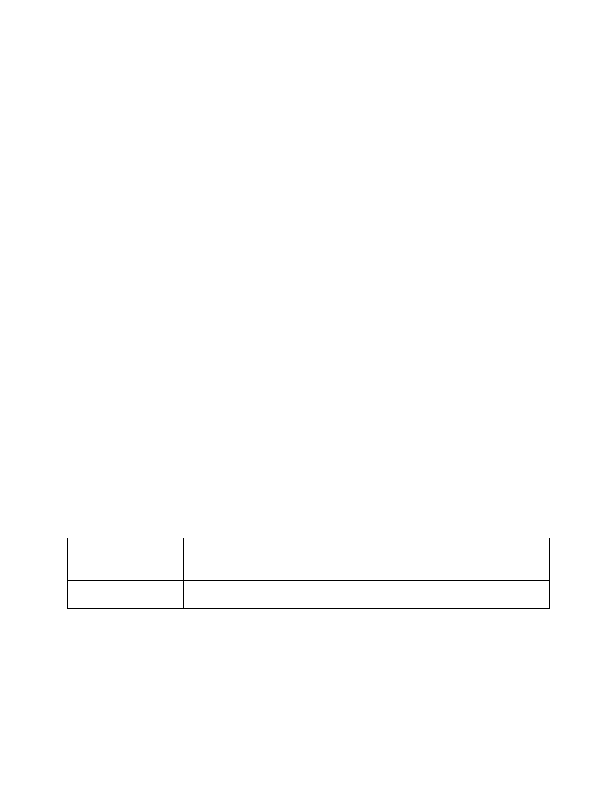
DEVICE OVERVIEW
1. IP65 Power/Data Connection Cover
2. Power/Data Fixture Linking Connection
3. B-Size 86mm Metal Gobo
4. Fixture Light Shield
5. Safety Cable Attachment Point (secure rotator to fixture)
8
Page 9

INSTALLATION GUIDELINES
IP65 RATED
An IP rated lighting device is one, which is commonly installed in outdoor environments
and has been designed with an enclosure that effectively protects the ingress (entry) of
external foreign objects such as dust and water. The International Protection (IP) rating
system is commonly expressed as "IP" (Ingress Protection) followed by two numbers (i.e.
IP65) where the numbers define the degree of protection. The first digit (Foreign Bodies
Protection) indicates the extent of protection against particles entering the device and the
second digit (Water Protection) indicates the extent of protection against water entering
the device. An IP65 rated device is one, which has been designed and tested to protect
against the ingress of dust (6) and high-pressure water jets from any direction (5).
MARINE/COASTAL ENVIRONMENT INSTALLATIONS
Please note although this device is IP rated, the device is NOT suitable for marine and/or
coastal environment installations. Installing this device in a marine and/or coastal
environment may cause corrosion and/or excessive wear to the interior and/or exterior
components of the device. Damages and/or performance issues resulting from installation
in a marine and/or coastal environment will void the manufactures warranty and will NOT
be subject to any warranty claims and/or repairs.
FLAMMABLE MATERIAL WARNING
Keep device minimum 5.0 feet (1.5m) away from flammable materials and/or pyrotechnics.
ELECTRICAL CONNECTIONS
A qualified electrician should be used for all electrical connections and/or installations.
DO NOT INSTALL DEVICE IF YOU ARE NOT QUALIFIED TO DO SO!
9
Page 10

GOBO DIMENSIONS
10
Page 11

GOBO INSTALLATION
1. Remove FRONT GOBO retainer-clip.
2. Remove included FRONT GOBO. Replace with desired GOBO, aligning the GOBO tab
(if included) into the holder notch. Install FRONT GOBO retainer-clip securely.
3. Remove REAR GOBO retainer-clip.
4. Remove included REAR GOBO. Replace with desired GOBO, aligning the GOBO tab (if
included) into the holder notch. Install REAR GOBO retainer-clip securely.
IF GOBO HAS BLACK HEAT COATING, FACE THIS SIDE TOWARDS THE LED!
FRONT
GOBO
REAR
GOBO
11
Page 12

ROTATOR INSTALLATION
1. Power CW/WW PROFILE HP IP fixture OFF and place on a flat stable surface.
2. Loosen GOBO slot cover screws (x2) on top of the fixture and slide open.
If the slot cover screws interfere with rotator installation, it may be necessary to
temporarily remove them for installation. Replace them after rotator installation.
IP GOBO Rotator
DMX Connection
orientation slot
12
Page 13

ROTATOR INSTALLATION
3. Remove rubber cover from the bottom of the fixture.
4. Position the rotator housing facing the front of the profile fixture, then install it into the
GOBO slot. Make sure it is fully seated and the rear radiused stop is flush with the
fixture shroud surface. Secure the 2 screws on fixture top GOBO slot cover.
5. Remove the IP65 rubber covers of the 5pin power/data linking connection on the
bottom of the rotator and on the profile fixture.
6. Connect the included 5pin power/data linking cable.
Front
Back
Radiused
Stop
13
Page 14

ROTATOR INSTALLATION
Fasten the carabiner of the included safety
cable to the rigging point on the rotator.
Wrap the safety cable through and around the
Mounting Yoke of the profile fixture.
Fasten the safety cable loop to the carabiner.
SAFETY CABLE
RIGGING POINT
SAFETY CABLE
The ROTATOR includes an integrated safety cable rigging point. (See image below.)
ALWAYS ATTACH INCLUDED SAFETY CABLE FROM THE ROTATOR TO THE
MOUNTING YOKE TO ENSURE THE ROTATOR WILL NOT FALL.
14
Page 15

DMX CONTROL
MODE / CHANNEL
VALUE
FUNCTION
3CH
6CH
8CH
2 2 3
GOBO ROTATOR
0-127
GOBO Indexing
128-189
Clockwise Rotation FAST to SLOW
190-193
NO Rotation
194-255
Counter-Clockwise Rotation SLOW to FAST
15
Page 16

SPECIFICATIONS
GOBO SIZE
B-Size Metal OD 86mm | ID 64.5mm
Holds (2) Gobos
CONTROL / CONNECTION
Bi-Directional Variable Speed Counter-Rotation and Full Indexable via DMX
5pin Power/Data (rotator to fixture proprietary linking cable included)
SIZE / WEIGHT
Length: 4.8” (121mm)
Width: 3.5” (89.7mm)
Vertical Height: 12.0” (306mm)
Weight: 2.0 lbs. (0.9 kg)
APPROVALS / RATINGS
CE | IP65
Specifications and improvements in the design of this unit and this manual are subject to change without any prior written notice.
FCC STATEMENT
This device complies with Part 15 of the FCC Rules. Operation is subject to the following two conditions: (1)
this device may not cause harmful interference, and (2) this device must accept any interference received,
including interference that may cause undesired operation.
FCC RADIO FREQUENCY INTERFERENCE WARNINGS & INSTRUCTIONS
This product has been tested and found to comply with the limits as per Part 15 of the FCC Rules. These
limits are designed to provide reasonable protection against harmful interference in a residential installation.
This device uses and can radiate radio frequency energy and, if not installed and used in accordance with
the included instructions, may cause harmful interference to radio communications. However, there is no
guarantee that interference will not occur in a particular installation. If this device does cause harmful
interference to radio or television reception, which can be determined by turning the device off and on, the
user is encouraged to try to correct the interference by one or more of the following methods:
• Reorient or relocate the device.
• Increase the separation between the device and the receiver.
• Connect the device to an electrical outlet on a circuit different from which the radio receiver is connected.
• Consult the dealer or an experienced radio/TV technician for help.
16
Page 17

DIMENSIONAL DRAWINGS
Specifications and improvements in the design of this unit and this manual are subject to change without any prior written notice.
17
Page 18

 Loading...