


Technical Specifications:
Model: Waterfall™
Lamp: SC150 120v/150w HTI
Voltage: 110~120v
Dimensions: 10”H x 12”W x 15”L
Colors 6 plus White
Weight: 24 Lbs
Fuse: 5 Amp
©Elation Lighting
Elation World Headquarters:
4295 Charter Street Los Angeles, CA 90058 USA
Tel: 323-582-2650 / Fax: 323-582-3108
Web: www.elationlighting.com / E-mail: info@elationlighting.com
User Instructions
Elation Lighting
4295 Charter Street
Los Angeles Ca. 90058
www.elationlighting.com

Introduction: Thank you for purchasing the Elation® Waterfall.
™
To
optimize the performance of this product, please read these operating
instructions carefully to familiarize yourself with the basic operations of
this unit. The Waterfall
™
is an effect that simulates moving water and
re. The Waterfall™ was created to meet the demands of theatrical
groups and for individuals that desire an incredible effect without strong
flashing lights or fog.
Customer Support: Elation® provides a toll free customer sup-
port line, to provide set up help and to answer any question should you
encounter problems during your set up or initial operation. You may also
visit us on the web at www.elationlighting.com for any comments or suggestions. Service Hours are Monday through Friday 9:00 a.m. to 5:00
p.m. Pacic Standard Time.
Voice: (800) 322-6337
Fax: (323) 582-2610
E-mail: support@elationlighting.com
Warning! To prevent or reduce the risk of electrical shock or re, do
not expose this unit to rain or moisture.
Caution! There are no user serviceable parts inside this unit. Do not
attempt any repairs yourself, doing so will void your manufactures warranty. In the unlikely event your unit may require service please contact
your nearest Elation dealer.
Wat erf all™ In troduct ion
©Elation Lighting® - www.elationlighting.com - Waterfall™ Instruction Manual Page 2
Wate rfa ll™ Unp ackin g
Every Waterfall™ has been thoroughly tested and has been shipped
in perfect operating condition. Carefully check the shipping carton for
damage that may have occurred during shipping. If the carton appears
to be damaged, carefully inspect your xture for any damage and be
sure all equipment necessary to operate the system has arrived intact.
In the case damage has been found or parts are missing, please contact our toll free customer support number for further instructions.
DISCHARGE LAMP WARNING!
This fixture is fitted with a discharge lamp which is highly susceptible to
damage if improperly handled. Never touch lamp with your bare fingers
as the oil from your hands will shorten lamp life. Also, never move the
fixture until the lamp has had ample time to cool. Remember, lamps
are not covered under warranty conditions.
Caution! Never open the unit when in use. Always disconnect the
main power before attempting to replace the lamp. Remember always
replace with the same type lamp and fuse.
1. Be sure to follow the proper procedures when handling discharge
lamp.
2. Remove the thumb screw on the trap door located at the rear of
the unit.
3. Pull down the trap door to expose the socket assembly.
4. Remove and replace the lamp.
5. Reassemble.
Wat erf all™ Cl eanin g
Wat erf all™ La mp Re placeme nt
Due to fog residue, smoke, and dust cleaning the internal and external
optical lenses must be carried out periodically to optimize light output.
1. Use normal glass cleaner and a soft cloth to wipe down the
outside casing.
2. Use a brush to wipe down the fan grill and remove as much
built up as possible.
3. Clean the external optics with glass cleaner and a soft cloth
every 20 days.
4. Clean the internal optics with glass cleaner and a soft cloth
every 30-60 days.
5. Always be sure to dry all parts completely before plugging the
unit in.
Cleaning frequency depends on the environment in which the fixture
operates (i.e. smoke, fog residue, dust, dew).
Wate rfa ll™ Wa rrant y Card
The Waterfall™ carries a two year limited warranty. We recommend
you fill out the enclosed warranty card to validate your purchase. All
returned service items whether under warranty or not, must be freight
pre-paid and accompany a R.A. Number. If the unit is under warranty,
you must provide a proof of purchase invoice.
©Elation Lighting® - www.elationlighting.com - Waterfall™ Instruction Manual Page 7
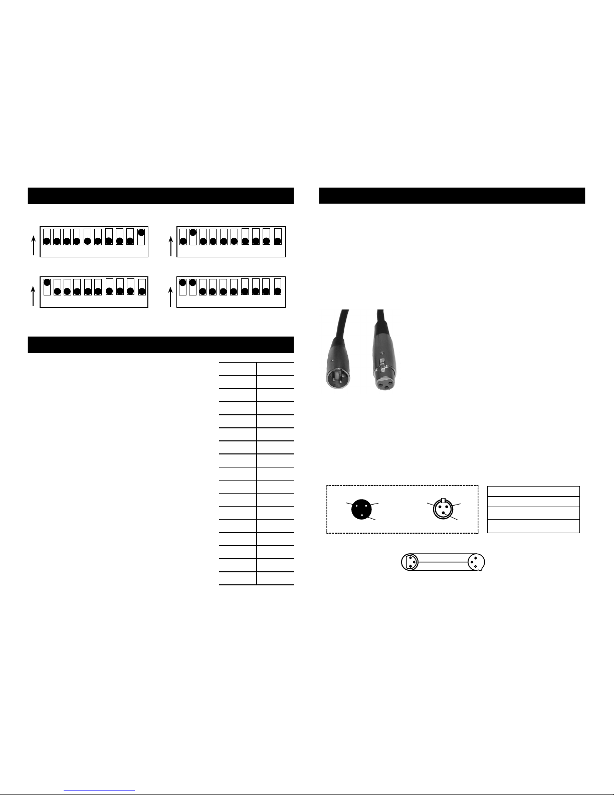
00-08
99-107
90-98
81-89
72-80
63-71
54-62
45-53
36-44
27-35
18-26
09-17
117-125
108-116
144-255
135-143
126-134
Blackout
Yell/Orng
Yellow
Grn/Yellow
Green
Blue/Grn
Blue
Red/Blue
Red
White/Red
White
1/2 White
Orng/Pink
Orange
Color Scroll
Half Pink
Pink
1 2
43 5 6
MASTER - HEAD 1
7 8 9
10
ON
1 2
43 5 6
HEAD 2
7 8 9
10
ON
1 2
43 5 6
HEAD 3
7 8 9
10
ON
1 2
43 5 6
HEAD 4
7 8 9
10
ON
Wat erf all™ Di p Swi tch Set tings
©Elation Lighting® - www.elationlighting.com - Waterfall™ Instruction Manual Page 6
Wat erf all™ DM X Trait s
The Waterfall™ uses one DMX channel. The
chart to the right details the DMX traits. The
color scroll option will increase in speed as the
DMX value progresses from 144 to 255.
Power Supply: Before plugging your unit in be sure the source volt-
age in your area matches the required voltage for your Elation® Waterfall.™ The Elation® Waterfall™ is available in a 115v and 230v version.
Line voltage may vary from venue to venue. Be sure to plug your unit
into a matching wall outlet before attempting to operate.
Data Cable (DMX Cable) Requirements (For DMX Operation
Only and Master-Slave): The Waterfall can be controlled via
DMX-512 protocol. The Elation® Waterfall™ is a single channel DMX
unit. The DMX address is set on the rear panel of the Waterfall. Your unit
and your DMX controller require a standard 3-pin
XLR connector for data input and data output
(Figure 1). If you are making your own cables,
be sure to use standard two conductor shielded
cable (This cable may be purchased at almost all
pro sound and lighting stores). Your cables should
be made with a male and female XLR connector
on either end of the cable. Also remember that
DMX cable must be daisy chained and can not be
split.
Notice: Be sure to follow gure three when making your own cables.
Do not use the ground lug on the XLR connector. Do not connect the
cable’s shield conductor to the ground lug or allow the shield conductor
to come in contact with the XLR’s outer casing. Grounding the shield
could cause a short circuit and erratic behavior.
©Elation Lighting® - www.elationlighting.com - Waterfall™ Instruction Manual Page 3
Figure 1
Figure 2
DMX512 IN
3-PIN XLR
REMOTE
CONTROL
INPUT
POWER
INPUT OUTPUT
SOUND
REMOTE
CONTROL
INPUT
POWER
INPUT OUTPUT
SOUND
REMOTE
CONTROL
INPUT
POWER
INPUT OUTPUT
DMX512
DMX+,DMX-,COMMON
1
2
3
Termination reduces signal errors and
avoi ds signal tr ansmiss ion proble ms
and inte rference. It is always adv isable
to connect a DMX terminal, (Resistance
120 Ohm 1/4 W) be tween PIN 2 (DMX-)
and PIN 3 (DMX +) of the la st fixtur e.
1
2
3
1
2
3
DMX +
DMX -
COMMON
DMX512 OUT
3-PIN XLR
Figure 3
Wate rfa ll™ Set Up
1 Ground
1 Ground
XLR Male Socket
XLR Pin Conguration
3 Hot
2 Cold
2 Cold
3 Hot
XLR Female Socket
Pin 3 = Data True (positive)
Pin 2 = Data Compliment (negative)
Pin 1 = Shield
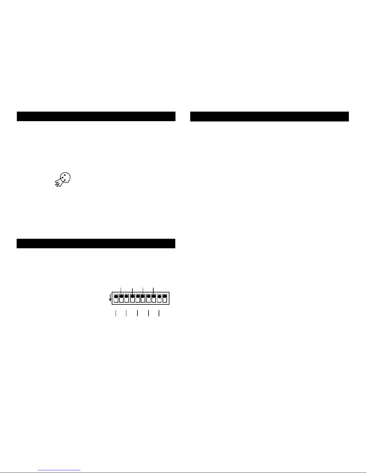
DMX stands for Digital Multiplex. This is a universal binary language used
as a form of communication between intelligent fixtures. Each dip switch
represents a binary value.
Dip Switch 1 address equals 1
Dip Switch 2 address equals 2
Dip Switch 3 address equals 4
Dip Switch 4 address equals 8
Dip Switch 5 address equals 16
Dip Switch 6 address equals 32
Dip Switch 7 address equals 64
Dip Switch 8 address equals 128
Dip Switch 9 address equals 256
Dip Switch 10 is used to control the Master/Slave operation. Turning dip
switch 10 on will activate that unit as a “Master Unit.”
Wate rfa ll™ Set Up
©Elation Lighting® - www.elationlighting.com - Waterfall™ Instruction Manual Page 4
POWER
SOUND
REMOTE
CONTROL
INPUT
POWER
INPUT OUTPUT
1
2
3
Termination reduces signal errors and
avoi ds signal tr ansmiss ion proble ms
and inte rference. It is always adv isable
to connect a DMX terminal, (Resistance
120 Ohm 1/4 W) be tween PIN 2 (DMX-)
and PIN 3 (DMX +) of the la st fixtur e.
Figure 4
Linking: Your unit comes with built in programs. These programs will
automatically run to the beat of music. For a more dramatic effect, link
several units together. Each unit can act a “Master Unit” that can control
up to 3 more units. Link the units together using standard DMX cable.
Follow the Master/Slave Dip Switch Chart on page 6 for proper dip
switch settings. The built programs are optimized for a four unit chase.
Wat erf all™ DM X Add re ssing
DMX CHANNEL
1 2 3 54 7 9 1086
ON
1 4 16 64 256
2 8 32 128
Wat erf all™ Op erati on
©Elation Lighting® - www.elationlighting.com - Waterfall™ Instruction Manual Page 5
Stand Alone: This function is used when using only one unit or
running more than one unit as individual fixtures.
A. Set dip switch 10 to the on position (see page 6).
B. Plug the unit in, the unit will react to sound via an internal
microphone.
C. Use the audio sensitivity knob on the rear of the unit to make the
unit more or less sensitive to sound. Turning the knob in a clock wise direction will make the unit more sensitive to sound.
Master / Slave Operation: This function will allow you to link up
to 4 units together. In this mode, the units will react to sound via the
master units internal microphone. The units will also run to the built
in programs.
A. Use XLR cables to daisy chain the fixtures together. Remembering
the female XLR is the output, and the male XLR is the input.
B. Be sure to follow the dip switch chart on the top of page 6.
C. For longer cable runs, we suggest a terminator at the last fixture in
the cable run (see terminator on page 4).
Universal DMX Control: This function allows you to use a universal
DMX controller such as the Elation
® Show Designer.™ The use of a
DMX controller will allow you to customize the use of fixtures allowing
you independent control of the color wheel and the ability to black out.
This will allow you to create your own programs or use your fixtures
as textured color changers.
A. The Waterfall™
is a one channel DMX fixture.
B. When using a DMX controller and setting up for DMX operation
follow the standard DMX Binary Code for a one (1) channel unit.
C. For help running in DMX mode consult the manual that comes
with your DMX controller.
D. For longer cable runs, we suggest a terminator at the last fixture in
the cable run (see terminator on page 4).
Special Note: Line Termination.
When longer runs of cable are
used, you may need to use a terminator on the last unit to avoid erratic
behavior. A terminator is a 90-120 ohm 1/4 watt resistor which is connected between pins 2 and 3 of a male XLR connector (DATA + and
DATA -). This unit is inserted in the female XLR connector of the last unit
in your daisy chain to terminate the line. Using a cable terminator will
decrease the possibilities of erratic behavior.
 Loading...