

Page 1
Unpacking: Thank you for purchasing the Ice Flow™ by Elation®.
Every unit has been thoroughly tested and has been shipped in perfect
operating condition. Carefully check the shipping carton for damage
that may have occurred during shipping. If the carton appears to be
damaged, carefully inspect your xture for any damage and be sure all
equipment necessary to operate the unit has arrived intact. In the event
damage has been found or parts are missing, please contact our toll
free customer support number for further instructions. Do not return this
unit to your dealer without rst contacting customer support.
Introduction: This unit is designed to produce a ground fog effect to
enhance dance floors, entry ways, and for halloween effects. Included
with this unit is a timer remote control. Please read the following instructions and safety precautions before attempting any installation or using
your new Ice Flow™.
Customer Support: Elation® provides a customer support line, to
provide help and to answer any question should you encounter problems during your set up or initial operation. You may also visit us on
the web at www.elationlighting.com for any comments or suggestions.
For service related issue please contact Elation®. Service Hours are
Monday through Friday 9:00 a.m. to 5:00 p.m. Pacic Standard Time.
Voice: (323) 582-3322
Fax: (323) 582-3311
E-mail: support@elationlighting.com
Warning! To prevent or reduce the risk of electrical shock or re, do
not expose this unit to rain or moisture.
Caution! There are no user serviceable parts inside this unit. Do not
attempt any repairs yourself, doing so will void your manufactures warranty. In the unlikely event your unit may require service please contact
your nearest Elation dealer.
Please do not discard the shipping cartoon in the trash. Please recycle
when ever possible.
Ice Flow™ I ntrod uctio n
©Elation Supply® - www.elationlighting.com - Ice Flow™ Instruction Manual Page 2
User Instructions
Revised 7/03
Elation Lighting
4295 Charter Street
Los Angeles Ca. 90058
www.elationlighting.com
Page 2

©Elation Supply® - www.elationlighting.com - Ice Flow™ Instruction Manual Page 4
The Ice Flow™™ carries a one year (365 days) limited warranty.
Please fill out the enclosed warranty card to validate your purchase.
All returned service items whether under warranty or not, must be
freight pre-paid and accompany a return authorization (R.A.) number. The R.A. number must be clearly written on the outside of the
return package. A brief description of the problem as well as the R.A.
number must also be written down on a piece of paper included in
the shipping carton. If the unit is under warranty, you must provide a
copy of your proof of purchase invoice. You may obtain a R.A. number by contacting our customer support team on our toll free customer support number. All packages returned to the service department
not displaying a R.A. number on the outside of the package will be
returned to the shipper.
Ice Flow™ Warran ty Re gistr ation
Ice Flow™ Safety Precauti ons
• Be sure to save the packing carton in the unlikely event the unit
may have to be returned for service
• Do not spill liquids into or on to your fogger. Be sure that all the
fog uid is kept inside the uid reservoir
• Be sure that the local power outlet match that or the required
voltage for your fog machine
• Do not remove the top cover under any conditions. There are no
user serviceable parts inside
• Disconnect the unit’s main power when left unused for long peri ods of time
• Never connect this unit to a dimmer pack
• Do not attempt to operate this unit, if it becomes damaged in anyway
• Never operate this unit when it’s cover is removed
• To reduce the risk of electrical shock or re, do not expose this
unit rain or moisture
• Do not attempt to operate this unit if the power cord has been fray ed or broken. Do not attempt to remove or break off the ground
prong from the electrical cord. This prong is used to reduce the
risk of electrical shock and re in case of an internal short
• Disconnect from main power before making any type of connection
• Never block the ventilation holes. Always be sure to mount this
unit in an area that will allow proper ventilation. Allow about 6”
(15cm) between this device and a wall
• This unit is intended for indoor use only, use of this product out doors voids all warranties
• Always mount this unit in a safe and stable matter
• Please route your power cord out of the way of foot trafc. Power
cords should be routed so they are not likely to be walked on,
pinched by items placed upon or against them
• Cleaning -The fixture should be cleaned only as recommended by
the manufacturer. See page 9 for cleaning details
• The unit should only be serviced by qualified service personnel
when:
A. The power-supply cord or the plug has been damaged.
B. Objects have fallen, or liquid has been spilled into the unit.
C. The unit has been exposed to rain or water.
D. The appliance does not appear to operate normally or
exhibits a marked change in performance.
Introduction................................................................................2
Customer Support.......................................................................2
Safety Precautions.......................................................................4
DMX Set Up.................................................................................5
Back Panel...................................................................................8
Set Up..........................................................................................9
Operating Instructions...............................................................10
Remote Control..........................................................................11
Trouble Shooting........................................................................12
Warranty...........................................................................13
Specications...........................................................................14
Ice Flow™ Tabl e of Contents
©Elation Supply® - www.elationlighting.com - Ice Flow™ Instruction Manual Page 3
Page 3
Ice Flow™ DMX Set Up cont.
©Elation Supply® - www.elationlighting.com - Ice Flow™ Instruction Manual Page 5 ©Elation Supply® - www.elationlighting.com - Ice Flow™ Instruction Manual Page 6
Ice Flow™ DMX Set Up
DMX-512: DMX is short for Digital Multiplex. This is a universal pro-
tocol used as a form of communication between intelligent fixtures and
controllers. A DMX controller sends DMX data instructions from the
controller to the fixture. DMX data is sent as serial data that travels
from fixture to fixture via the DATA “IN” and DATA “OUT” XLR terminals located on all DMX fixtures (most controllers only have a DATA
“OUT” terminal).
DMX Linking: DMX is a language allowing all makes and models of
different manufactures to be linked together and operate from a single
controller, as long as all xtures and the controller are DMX compliant. To ensure proper DMX data transmission, when using several
DMX fixtures try to use the shortest cable path possible. The order
in which fixtures are connected in a DMX line does not influence the
DMX addressing. For example; a fixture assigned a DMX address of 1
may be placed anywhere in a DMX line, at the beginning, at the end,
or anywhere in the middle. When a fixture is assigned a DMX address
of 1, the DMX controller knows to send DATA assigned to address 1 to
that unit, no matter where it is located in the DMX chain.
Dip-switches in DMX mode: This unit uses dip switches to assign a
DMX address. Each dip switch represents a binary value.
Dip Switch 1 address equals 1
Dip Switch 2 address equals 2
Dip Switch 3 address equals 4
Dip Switch 4 address equals 8
Dip Switch 5 address equals 16
Dip Switch 6 address equals 32
Dip Switch 7 address equals 64
Dip Switch 8 address equals 128
Dip Switch 9 address equals 256
ON
1 98765432
10
1282 8 32
256651641
SP
DMX CHANNEL
Figure 1
Each dip switch has a preset value. A specific DMX address is set by
combining the dip switches that sum your desired value. For example:
To achieve a DMX address of 21, combine dip switches 1, 3, and 5.
Sense dip switch 1 has a value of 1, dip switch 3 has a value of 4, and
dip switch 5 has a value of 16, the combination of the create a DMX
value of 21.
Set DMX address 21: Set DMX address 201:
Dip-switches # 1 = 1 Dip-switches # 1 = 1
3 = 4 4 = 8
5 = 16 7 = 64
= 21 8 = 128
= 201
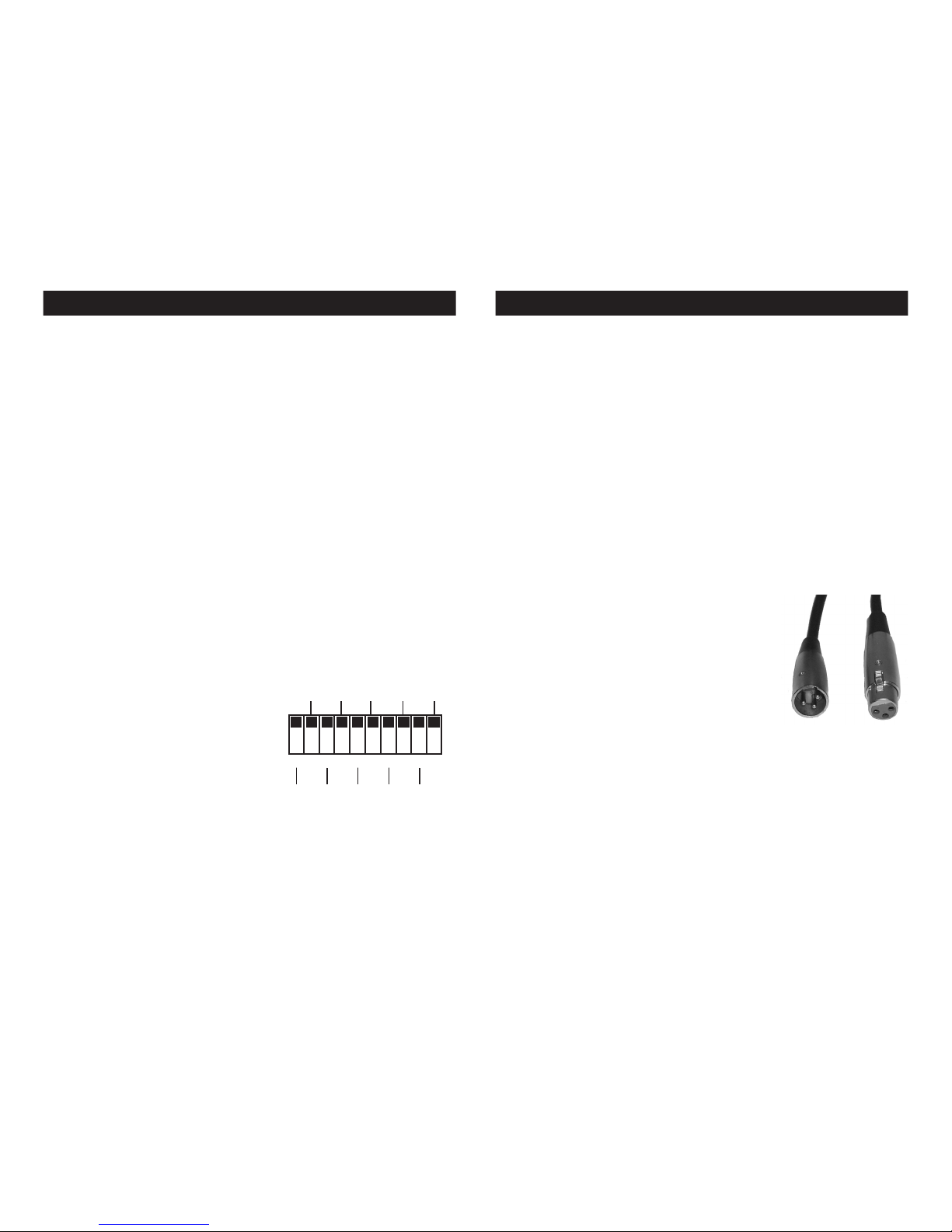
Data Cable (DMX Cable) Requirements (For DMX and Master/
Slave Operation): The Ice Flow™ can be controlled via DMX-512
protocol. The Elation Professional® Ice Flow™ is a one channel DMX
unit. The DMX address is set on the rear panel of the Ice Flow™. Your
unit and your DMX controller require a standard
3-pin XLR connector for data input and data
output (Figure 1). If you are making your own
cables, be sure to use standard two conductor
shielded cable (This cable may be purchased at
almost all pro sound and lighting stores). Your
cables should be made with a male and female
XLR connector on either end of the cable. Also
remember that DMX cable must be daisy chained
and can not be split.
Notice: Be sure to follow gures two and three when making your own
cables. Do not use the ground lug on the XLR connector. Do not connect the cableʼs shield conductor to the ground lug or allow the shield
conductor to come in contact with the XLRʼs outer casing. Grounding
the shield could cause a short circuit and erratic behavior.
Page 4

Ice Flow™ Back Panel Ice Flow™ DMX Set Up cont.
Special Note: Line Termination.
When longer runs of cable are used, you may need to use a terminator
on the last unit to avoid erratic behavior. A terminator is a 90-120 ohm 1/
4 watt resistor which is connected between pins 2 and 3 of a male XLR
connector (DATA + and DATA -). This unit is inserted in the female XLR
connector of the last unit in your daisy chain to terminate the line. Using
a cable terminator will decrease the possibilities of erratic behavior.
Figure 2
DMX512 IN
3-PIN XLR
REMOTE
CONTROL
INPUT
POWER
INPUT OUTPUT
SOUND
REMOTE
CONTROL
INPUT
POWER
INPUT OUTPUT
SOUND
REMOTE
CONTROL
INPUT
POWER
INPUT OUTPUT
DMX512
DMX+,DMX-,COMMON
1
2
3
Termination reduces signal errors and
avoi ds signal tr ansmiss ion proble ms
and int erference. It is always adv isable
to connect a DMX terminal, (Resistance
120 Ohm 1/4 W) b etween PIN 2 (DMX-)
and PIN 3 (DMX +) of the la st fixtu re.
1
2
3
1
2
3
DMX +
DMX -
COMMON
DMX512 OUT
3-PIN XLR
Figure 3
POWER
SOUND
REMOTE
CONTROL
INPUT
POWER
INPUT OUTPUT
1
2
3
Termination reduces signal errors and
avoi ds signal tr ansmiss ion proble ms
and int erference. It is always adv isable
to connect a DMX terminal, (Resistance
120 Ohm 1/4 W) b etween PIN 2 (DMX-)
and PIN 3 (DMX +) of the la st fixtu re.
Figure 4
1 Ground
1 Ground
XLR Male Socket
XLR Pin Conguration
3 Hot
2 Cold
2 Cold
3 Hot
XLR Female Socket
Pin 3 = Data True (positive)
Pin 2 = Data Compliment (negative)
Pin 1 = Ground
1
6
5
4
3
2
7
1. Drain Switch - Selects the mode in which the water is
drained out of the unit, either automatic or manual. See
page 12 for details.
2. XLR Input Jack - This jack is used to accept an incoming
DMX signal.
3. XLR Output Jack - This jack is used to transmit the incom ing DMX signal to another DMX xture, or transmit a Master/
Slave signal to the next unit in the chain. For best results in
DMX or Master/Slave mode terminate this jack if it is the last
unit in the chain.
8
©Elation Supply® - www.elationlighting.com - Ice Flow™ Instruction Manual Page 8©Elation Supply® - www.elationlighting.com - Ice Flow™ Instruction Manual Page 7
9
5-Pin XLR DMX Connectors.
Some manufactures use 5-pin XLR
connectors for DATA transmission in place of 3-pin. 5-pin XLR xtures
may be implemented in a 3-pin XLR DMX line. When inserting standard 5-pin XLR connectors in to a 3-pin line a cable adaptor must be
used, these adaptors are readily available at most electric stores. The
chart below details a proper cable conversion.
Conductor 5-Pin XLR Male (In)3-Pin XLR Female (Out)
Pin 1
Pin 5 - Do Not Use
Pin 4 - Do Not Use
Pin 3
Pin 2
Pin 1
Pin 3
Pin 2
Not Used
Not Used
Data True (+ signal)
Data Compliment (- signal)
Ground/Shield
3-Pin XLR to 5-Pin XLR Conversion
Page 5

4. Timer Remote Input - Used to connect the timer remote
control. See page 11 for timer remote instructions.
5. AC Cord - Connect only to a matching power outlet. Never
use this xture is the ground prong has been removed or
broken off.
6. Fuse Holder - This housing stores the 2 amp GMA protec tive fuse. Always replace with the exact same type fuse,
unless otherwise instructed, by an authorized American DJ®
service technician.
7. Power Switch - The main on/off switch.
8. Dipswitches - In DMX mode these switches are used to
assign a DMX address to the unit. In DMX mode each switch
corresponds to a specic value based on binary code. See
page 5 for a detailed explanation of DMX binary code.
9. Drain Hole - The water that results from the ice melting is
drained out of the unit through this hole. The supplied water
tube is connected to this hole.
©Elation Supply® - www.elationlighting.com - Ice Flow™ Instruction Manual Page 10©Elation Supply® - www.elationlighting.com - Ice Flow™ Instruction Manual Page 9
Ice Flow™ B ack P anel cont.
Ice Flow™ Set-Up
1. Open the shipping carton and carefully remove the unit from the
shipping carton.
2. Be sure to remove all the packing material especially around the
nozzle.
3. Set the machine on a flat dry surface and unscrew the knob on
the top of the unit. Open the top of the unit, and fill the inside of
the Ice Flow™ with ice.
4. Remove the reservoir cap located on the top of the machine.
5. Fill the Ice Flow™ reservoir with Elation brand fog juice
only and replace the cap.
6. Insert the water tube into the water bag. When the ice melts, the
water will empty into the bag (see Drain Switch below).
7. Remove the remote control from the carton. Firmly attach the
remote control to the remote control socket located on the rear
unit.
Always be sure to maintain an adequate supply of Elation® Brand
Fog juice™ in the fluid reservoir. Running the fog machine dry will
cause pump failure and or clogging. This is the largest cause of failure in fog machines.
8. Plug the unit in to a matching power supply and flip the power
switch to the on position.
9. Allow the unit to heat up. When the unit is ready to fog, the green
LED on the remote will light up, indicating the unit is ready.
Ice Flow™ Set-Up cont.
This unit has a 10 minute warm up time. After the unit is warmed
up follow the directions below for ground fogger operation.
Place your fog machine in a well ventilated area. Be sure your ground
fogger is placed on a flat, level surface. Always maintain an adequate
supply of Elation Fog Juice™ in the fluid reservoir. Running the fog
machine dry will cause pump failure and or clogging. Running a fog
machine dry is the largest cause of fog machine failure. Only Elation
Fog Juice™ is recommended and not all fog juice is created equal.
Plug your fog machine into a standard 110V/120V supply. Once the
machine is plugged in and turned on, the power switch will begin to
glow indicating the unit is receiving power.
Universal DMX Control: This function allows you to use a univer-
sal DMX-512 controller such as the Elation® DMX Operator™ or Show
Designer to control fog output.
1. The Ice Flow™ uses one DMX channel. Channel value 0
to 64 will not produce fog output, channel value 65 to 255 the
Ice Flow™ will produce fog.
3. To control your fixture in DMX mode, follow the set-up procedures
on pages 5 - 6 as well as the set-up specifications that are includ ed with your DMX controller.
4. Use the controller’s faders to control the DMX fixture trait.
5. For longer cable runs (more than a 100 feet) use a terminator on
the last fixture.
6. For help operating in DMX mode consult the manual included
with your DMX controller.
Ice Flow™ Oper ating Instructions
Page 6

Duration:
1. This function allows you to set how long the fog burst will last,
when in timer mode.
2. You can adjust the length of the fog burst from one second to
200 seconds.
3. To set the duration, turn the duration knob in a clockwise/counter clockwise direction. Turning the knob clockwise will increase the
duration, turning the knob counter-clockwise will decrease the
duration.
Interval:
1. In timer mode, this function allows you to set the time interval
between fog bursts.
2. Fog burst interval can be set from one second to 200 seconds.
3. To set the interval turn the interval knob in a clockwise/counter clockwise direction. Turning the knob clockwise will increase the
interval, turning the knob counter-clockwise will decrease the
interval.
Timer On/Off:
1. This Function allows you to set the fogger on an automatic setting.
You can set the Interval, Duration, and as described at the top of
the page.
2. This button allows you turn the timer function on and off. A glowing
yellow LED will indicate this function is activated.
Continuous:
When this button is pushed the fogger will run continuously without
stopping until the button is pushed again or the tank runs out of fog
fluid.
Manual:
When this button is pressed it will emit fog as long as the button is
held down.
Ice Flow™ Remote C ontro l Ins truct ions
©Elation Supply® - www.elationlighting.com - Ice Flow™ Instruction Manual Page 11 ©Elation Supply® - www.elationlighting.com - Ice Flow™ Instruction Manual Page 12
Ice Flow™ Trouble Shoot ing
If you experience low fog output, pump noise, or no fog output at all,
disconnect and discontinue use immediately. Do not continue pushing the remote controlʼs activation button as this may damage the Ice
Flow™. Check fluid level, the external fuse or breaker, remote connection, and be sure the wall outlet is sending power. If all of the above
appear to be okay, and the unit fails to operate correctly, the unit may
require service. Please contact customer support for further instructions. Please do not return the unit to your dealer without contacting
customer support first.
To help prevent the unit from clogging, use Elation® Clean Machine™
liquid. Clean Machine is recommended when storing your fogger for
more than 1 week, or at least once a month as normal maintenance
under regular usage. Clean Machine removes particle build up in the
heater and gives longer life to the fog machine. Clean Machine is like
a tune up for your fog machine! Clean Machine is available in gallon
or quart bottles.
Ice Flow™ Clean Mach ine
Ice Flow™ Dr ainin g Swi tch
The drain switch on the back is for emptying the water produced by
the melted ice, out of the unit. There are two modes of draining the
water, automatically and manually.
Auto ( I ) - A sensor inside the unit will activate the pump when a certain water level is reached. The pump will empty the water out of the
unit.
Manual ( II ) - When the manual mode of draining is selected, the
pump will turn on instantly and pump whatever water is in the unit, out
of the unit.
Page 7

1 YEAR LIMITED WARRANTY
A. Elation® hereby warrants, to the original purchaser, Elation® products to be free of
manufacturing defects in material and workmanship for a period of one year (365 days)
from the date of purchase. This warranty shall be valid only if the product is purchased
within the United States of America, including possessions and territories. It is the owner’s
responsibility to establish the date and place of purchase by acceptable evidence, at the
time service is sought.
B. For warranty service, send the product only to the Elation® factory. All shipping charges
must be pre-paid. If the requested repairs or service (including parts replacement) are
within the terms of this warranty, Elation® will pay return shipping charges only to a designated point within the United States. If the entire instrument is sent, it must be shipped
in its original package. No accessories should be shipped with the product. If any accessories are shipped with the product, Elation® shall have no liability whatsoever for loss of or
damage to any such accessories, nor for the safe return thereof.
C. This warranty is void if the serial number has been altered or removed; if the product is
modied in any manner which Elation® concludes, after inspection, affects the reliability of
the product; if the product has been repaired or serviced by anyone other than the Elation®
factory unless prior written authorization was issued to purchaser by Elation®; if the product
is damaged because not properly maintained as set forth in the instruction manual.
D. This is not a service contract, and this warranty does not include maintenance, cleaning or periodic check-up. During the period specied above, Elation® will replace defective
parts at its expense, and will absorb all expenses for warranty service and repair labor by
reason of defects in material or workmanship. The sole responsibility of Elation® under
this warranty shall be limited to the repair of the product, or replacement thereof, including
parts, at the sole discretion of Elation®. All products covered by this warranty were manufactured after January 1, 1990, and bear identifying marks to that effect.
E. Elation® reserves the right to make changes in design and/or improvements upon its
products without any obligation to include these changes in any products theretofore
manufactured.
F. No warranty, whether expressed or implied, is given or made with respect to any accessory supplied with products described above. Except to the extent prohibited by applicable
law, all implied warranties made by Elation® in connection with this product, including warranties of merchantability or tness, are limited in duration to the warranty period set forth
above. And no warranties, whether expressed or implied, including warranties of merchantability or tness, shall apply to this product after said period has expired. The consumer’s
and or Dealer’s sole remedy shall be such repair or replacement as is expressly provided
above; and under no circumstances shall Elation® be liable for any loss or damage, direct
or consequential, arising out of the use of, or inability to use, this product.
G. This warranty is the only written warranty applicable to Elation® Products and supersedes all prior warranties and written descriptions of warranty terms and conditions heretofore published.
H. Lamps are not covered under this warranty.
Ice Flow™ Warranty
©Elation Supply® - www.elationlighting.com - Ice Flow™ Instruction Manual Page 13
MODEL - Ice Flow™
WEIGHT: 49 Lbs./ 24.5 Kgs.
DIMENSIONS: 23.8” (L) x 12.4” (W) x 14.1” (H)
FUSE: 10A 125V/ 5A 250V
SUPPLY VOLTAGE: 120V
WARM UP TIME: 10 Minutes
HEATER: 1000 Watts
TANK CAPACITY: 0.5 Liter Removable Tank
OUTPUT: 10,000 cubic feet per minute
FLUID TYPE: Water Base Elation Fog juice™
DUTY CYCLE: Not to exceed 6 hours plugged in.
*Voltage is preset at the factory and may not be changed
Ice Flow™ Sp ecifi catio ns
Please Note: Specications and improvements in the design
of this unit and this manual are subject to change without any
prior written notice.
©Elation Supply®
A Division of the Elation® Group of Companies
4295 Charter Street Los Angeles, CA 90058 USA
Tel: 323-582-3322 Fax: 323-582-3311
Web: www.elationlighting.com E-mail: info@elationlighting.com
 Loading...