

Elation EVENT PANEL SYSTEM User Instructions
EVENT PANEL
SYSTEM
Event Panel System™ Introduction
Unpacking: Thank you for purchasing the Event Panel System™ by
Elation Professional®. Every Event Panel System™ has been thoroughly
tested and has been shipped in perfect operating condition. Carefully
check the shipping carton for damage that may have occurred during
shipping. If the carton appears to be damaged, carefully inspect your
xture for any damage and be sure all accessories necessary to operate
the unit has arrived intact. In the case damage has been found or parts
are missing, please contact our toll free customer support number for
further instructions. Do not return this unit to your dealer without rst
contacting customer support.
Introduction: The Elation Professional® Event Panel System™ is part
of a continuing pursuit for creating high quality affordable intelligent fixtures. The Event Panel System™ is a DMX intelligent LED color stage
wash. This fixture includes a battery pack/charger so that you are able
to take it on the go and not worry about a power outlet. This wash can
be used in a stand alone mode or connected in a Master/Slave conguration. The unit can also be controlled via DMX controller. This wash
has four operating modes: Sound Active mode, Auto mode, Program
mode, RGB mode, and DMX control mode.
Customer Support: Elation® provides a toll free customer support
line, to provide set up help and to answer any question should you
encounter problems during your set up or initial operation. You may
also visit us on the web at www.elationlighting.com for any comments
or suggestions. Service Hours are Monday through Friday 9:00 a.m. to
5:00 p.m. Pacic Standard Time.
Voice: (323) 582-3322
Fax: (323) 832-9142
E-mail: support@elationlighting.com
Warning! To prevent or reduce the risk of electrical shock or re, do
not expose this unit to rain or moisture.
Rev. 4/09
User Instructions
©Elation Professional®
Los Angeles CA. 90040
www.elationlighting.com
6122 S. Eastern Ave.
Caution! There are no user serviceable parts inside this unit. Do not
attempt any repairs yourself, doing so will void your manufactures warranty. In the unlikely event your unit may require service please contact
Elation®.
PLEASE recycle the shipping carton when ever possible.
©Elation Lighting® - www.elationlighting.com - Event Panel System™ User Manual Page 2
Event Panel System™ General Instructions
Event Panel System™ Safety Precautions
To optimize the performance of this product, please read these
operating instructions carefully to familiarize yourself with the basic
operations of this unit. These instructions contain important safety
information regarding the use and maintenance of this unit. Please
keep this manual with the unit, for future reference.
Event Panel System™ Features
• Battery Pack/Charger
• 288 Ultra Bright LEDs
• Mulit-Colors
• Color Strobe
• Electronic Dimming 0-100%
• Built in Microphone
• DMX-512 protocol
• 8 DMX Channel Modes: 2, 3, 4, 5, 6, 7, 14, & 26 DMX Channels
• WR L.E.D. Remote
Event Panel System™ Warranty Registration
The Event Panel System™ carries a 2 year (730 days) limited warranty. Please fill out the enclosed warranty card to validate your purchase
and warranty. You may also register your product online at www.elationlighting.com. All returned service items whether under warranty or
not, must be freight pre-paid and accompany a return authorization
(R.A.) number. If the unit is under warranty you must provide a copy
of your proof of purchase invoice. Please contact Elation® customer
support for a R.A. number.
• To reduce the risk of electrical shock or re, do not expose this unit
rain or moisture
• Do not spill water or other liquids into or on to your unit.
• Be sure that the local power outlet match that of the required volt age for your unit.
• Do not attempt to operate this unit if the power cord has been
frayed or broken. Do not attempt to remove or break off the ground
prong from the electrical cord. This prong is used to reduce the risk
of electrical shock and re in case of an internal short.
• Disconnect from main power before making any type of connection.
• Do not remove the cover under any conditions. There are no user
serviceable parts inside.
• Never operate this unit when it’s cover is removed.
• Never plug this unit in to a dimmer pack
• Always be sure to mount this unit in an area that will allow proper
ventilation. Allow about 6” (15cm) between this device and a wall.
• Do not attempt to operate this unit, if it becomes damaged.
• This unit is intended for indoor use only, use of this product out`
doors voids all warranties.
• During long periods of non-use, disconnect the unit’s main power.
• Always mount this unit in safe and stable matter.
• Power-supply cords should be routed so that they are not likely to
be walked on or pinched by items placed upon or against them,
paying particular attention to the point they exit from the unit.
• Cleaning -The fixture should be cleaned only as recommended by
t he manufacturer. See page 17 for cleaning details.
• Heat -The appliance should be situated away from heat sources
such as radiators, heat registers, stoves, or other appliances (inclu d ing amplifiers) that produce heat.
• The fixture should be serviced by qualified service personnel when:
A. The power-supply cord or the plug has been damaged.
B. Objects have fallen, or liquid has been spilled into the appliance.
C. The appliance has been exposed to rain or water.
D. The appliance does not appear to operate normally or exhibits a
marked change in performance.
©Elation® - www.elationlighting.com - Event Panel System™ User Manual Page 4©Elation® - www.elationlighting.com - Event Panel System™ User Manual Page 3
Event Panel System™ Set Up
DMX512 IN
3-PIN XLR
REMOTE
CONTROL
INPUT
POWER
INPUT OUTPUT
SOUND
REMOTE
CONTROL
INPUT
POWER
INPUT OUTPUT
SOUND
REMOTE
CONTROL
INPUT
POWER
INPUT OUTPUT
DMX512
DMX+,DMX-,COMMON
1
2
3
Terminatio n re duces signal errors and
avo ids signal tran smis sion problem s
and interference. It is always advisable
to connect a DMX terminal, (Resistance
120 Ohm 1/4 W) between PIN 2 (DMX-)
and PIN 3 (DMX +) of the last fixture.
1
2
3
1
2
3
DMX +
DMX -
COMMON
DMX512 OUT
3-PIN XLR
POWER
SOUND
REMOTE
CONTROL
INPUT
POWER
INPUT OUTPUT
1
2
3
Terminatio n re duces signal errors and
avo ids signal tran smis sion problem s
and interference. It is always advisable
to connect a DMX terminal, (Resistance
120 Ohm 1/4 W) between PIN 2 (DMX-)
and PIN 3 (DMX +) of the last fixture.
Event Panel System™ Set Up
Power Supply: The Elation® Event Panel System™ is a 100v ~ 220v
unit. Because of voltage setup of the unit you do not have to worry
about wall output voltage. This unit is compatiable with all wall outputs.
DMX-512: DMX is short for Digital Multiplex. This is a universal pro-
tocol used as a form of communication between intelligent fixtures
and controllers. A DMX controller sends DMX data instructions from
the controller to the fixture. DMX data is sent as serial data that travels from fixture to fixture via the DATA “IN” and DATA “OUT” XLR terminals located on all DMX fixtures (most controllers only have a DATA
“OUT” terminal).
DMX Linking: DMX is a language allowing all makes and models of
different manufactures to be linked together and operate from a single
controller, as long as all xtures and the controller are DMX compliant. To ensure proper DMX data transmission, when using several
DMX fixtures try to use the shortest cable path possible. The order
in which fixtures are connected in a DMX line does not influence the
DMX addressing. For example; a fixture assigned a DMX address of 1
may be placed anywhere in a DMX line, at the beginning, at the end,
or anywhere in the middle. When a fixture is assigned a DMX address
of 1, the DMX controller knows to send DATA assigned to address 1
to that unit, no matter where it is located in the DMX chain.
Data Cable (DMX Cable) Requirements (For DMX Operation):
The Event Panel System™ can be controlled via DMX-512 protocol. The
Event Panel System™ can be a two, three, four, ve, six, seven, 14,
and 26 channel DMX unit. The DMX address is set on the top panel of
the Event Panel System™. Your unit and your DMX controller require
an approved DMX-512 110 Ohm Data cable for data input and data
output (Figure 1). We recommend Accu-Cable
DMX cables. If you are making your own cables,
be sure to use standard 110-120 Ohm shielded
cable (This cable may be purchased at almost all
pro lighting stores). Your cables should be made
with a male and female DMX connector on either
end of the cable. Also remember that DMX cable
must be daisy chained and can not be split.
Figure 1
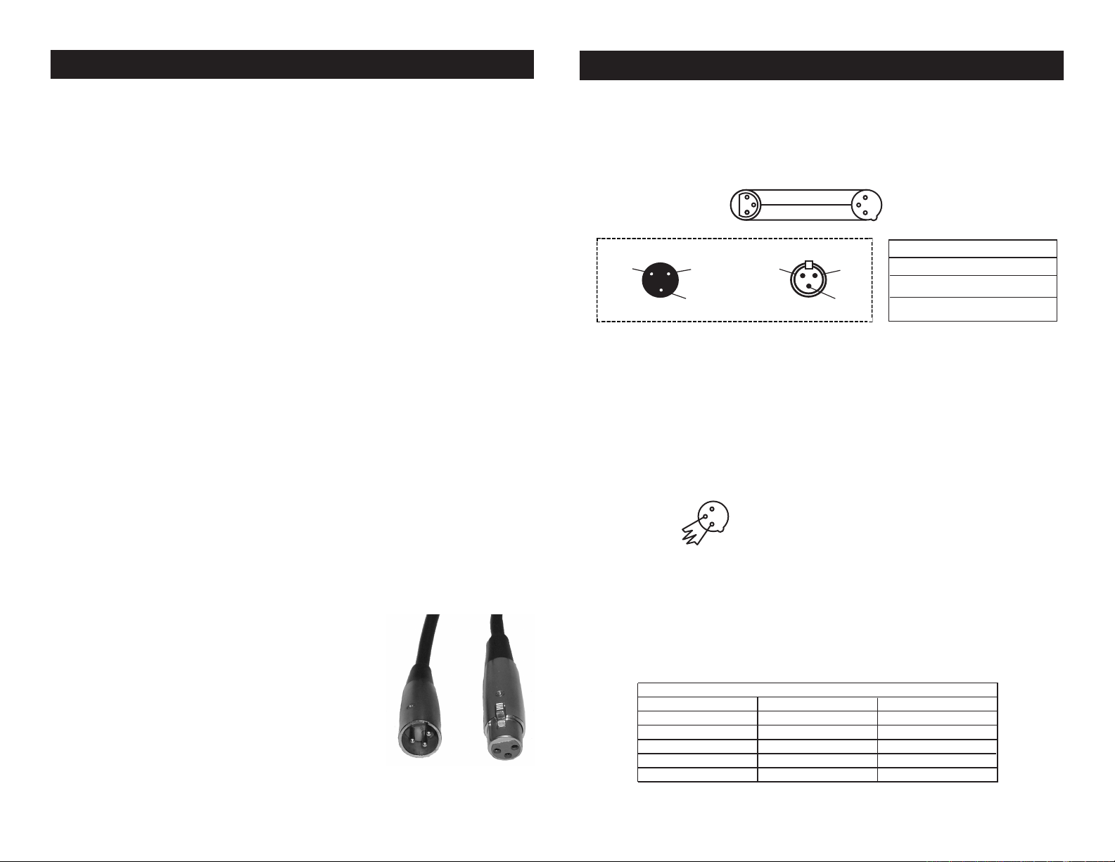
Notice: Be sure to follow gures two and three when making your own
cables. Do not use the ground lug on the XLR connector. Do not connect the cable’s shield conductor to the ground lug or allow the shield
conductor to come in contact with the XLR’s outer casing. Grounding
the shield could cause a short circuit and erratic behavior.
Figure 2
XLR Male Socket
1 Ground
2 Cold
3 Hot
Figure 3
Special Note: Line Termination.
used, you may need to use a terminator on the last unit to avoid erratic
behavior. A terminator is a 110-120 ohm 1/4 watt resistor which is connected between pins 2 and 3 of a male XLR connector (DATA + and
DATA -). This unit is inserted in the female XLR connector of the last
unit in your daisy chain to terminate the line. Using a cable terminator
(ADJ part number Z-DMX/T) will decrease the possibilities of erratic
behavior.
5-Pin XLR DMX Connectors.
512 data cables for DATA transmission in place of 3-pin. 5-pin DMX
xtures may be implemented in a 3-pin DMX line. When inserting stan-
dard 5-pin data cables in to a 3-pin line a cable adaptor must be used,
these adaptors are readily available at most electric stores. The chart
below details a proper cable conversion.
Conductor 5-Pin XLR Male (In)3-Pin XLR Female (Out)
Ground/Shield
Data Compliment (- signal)
Data True (+ signal)
Not Used
Not Used
XLR Female Socket
2 Cold
1 Ground
3 Hot
When longer runs of cable are
Some manufactures use 5-pin DMX-
3-Pin XLR to 5-Pin XLR Conversion
Pin 1
Pin 2
Pin 3
XLR Pin Conguration
Pin 1 = Ground
Pin 2 = Data Compliment (negative)
Pin 3 = Data True (positive)
Figure 4
Pin 1
Pin 2
Pin 3
Do Not Use
Do Not Use
©Elation® - www.elationlighting.com - Event Panel System™ User Manual Page 5
©Elation® - www.elationlighting.com - Event Panel System™ User Manual Page 6

Event Panel System™ Operating Instructions
Event Panel System™ Operating Instructions
Note: To deactivate the Elation intro scroll, first make sure power
is off. With the power off, press and hold the SET UP, MODE and
DOWN buttons and turn the power ON all at the same time. To activate the Elation intro scroll, press and hold the SET UP, MODE, and
UP buttons and turn the power ON all at the same time.
Operating Modes:
You can use the Event Panel System™ in either a stand alone mode
or a master/slave configuration, there are 5 modes to choose from:
• Programs Mode - Select one of 14 different programs and adjust
the different features of the program.
• Auto Run - The unit will automatically chase through the 14 differ-
ent programs.
• Sound-Active mode - The unit will react to sound, chasing through
the built in programs.
• RGB mode - Choose a desired color to stay static, or adjust and
intensitys of the RGB colors to create a desired color.
• DMX control mode - This function will allow you to control each
individual fixtures traits with a standard DMX 512 controller such as
as the Elation® Show Designer™.
Master-Slave Operation:
This function will allows you to link units together to run in a MasterSlave mode. In Master-Slave operation one unit will act as the controlling unit and the others will react to the controlling units built-in
programs. Any unit can act as a Master or as a Slave however, only
one unit can be programmed to act as the “Master.”
Master-Slave Connections and Settings:
1. Daisy chain your units via the XLR connector on the rear of the
unit. Use approved DMX-512 data cables to link your units to gether. Remember that the Male XLR connector is the input and
the Female XLR connector is the output. The first unit in the chain
(master) will use the female XLR connector only. The last unit in
the chain will use the male XLR connector only.
2. Using the Master unit, choose your desired mode or program and
connect the “Slave” unit or units.
3. On the “Slave” unit(s) press the MODE button until “SLAVE” is
displayed. They will now follow the “Master” unit.
©Elation® - www.elationlighting.com - Event Panel System™ User Manual Page 7
Programs Mode:
There are 14 programs to choose from.
Notes: Program 1 is “Static” so you can only choose from 7 different Colors and Blackout. Programs 2-12 you can adjust the
Speed of the program and the Fade Time. Programs 13-14 you
can adjust the Speed, Fade Time, and First Color and Second
Color of the Color Flow.
1. Plug the fixture in and press the MODE button. The Program Mode
is after Sound Active mode in the menu.
2. Select your desired program in by pressing either the UP or DOWN
buttons. There are 14 programs to choose from.
3. After you have selected your desired program, press the SETUP
button to adjust the different features the program has. Please see
above to understand what program features can be adjusted.
When you are adjusting a feature a small line will appear
underneath the feature or next to it so that you know what you
are adjusting.
FEATURES AND ADJUSTMENTS
• When “S.XX” is displayed you are adjusting the speed of the pro-
gram. Use the UP or DOWN buttons to adjust. The speed can be
adjusted from “S.01” the slowest, to “S.100” the fastest. Press the
SETUP button when you are finished, to either go to the next fea-
ture adjustment or to return to the Program menu. NOTE: This
adjustment is only available with Programs 2-14.
• When “F.XX” is displayed you are adjusting the fade time of the
program. Use the UP or DOWN buttons to adjust. The fade time
can be adjusted from “F.01” the slowest, to “F.100” the fastest.
Press the SETUP button when you are finished, to either go to the
next feature adjustment or to return to the Program menu. NOTE:
This adjustment is available with Programs 1-14.
• When “1” is displayed you are adjusting the first color of the
color flow. Use the UP or DOWN buttons to adjust. Scroll through
the colors to find your desired color. Press the SETUP button when
you are finished, to go to the next feature adjustment. “2” will be
displayed you are now adjusting the second color of the color flow.
Use the UP or DOWN buttons to adjust. Scroll through the colors to
find your desired color. Press the SETUP button when you are fin ished, to return to the Program menu. NOTE: This adjustment is
©Elation® - www.elationlighting.com - Event Panel System™ User Manual Page 8
 Loading...