

Elation EPV IMAGE VSC User Manual
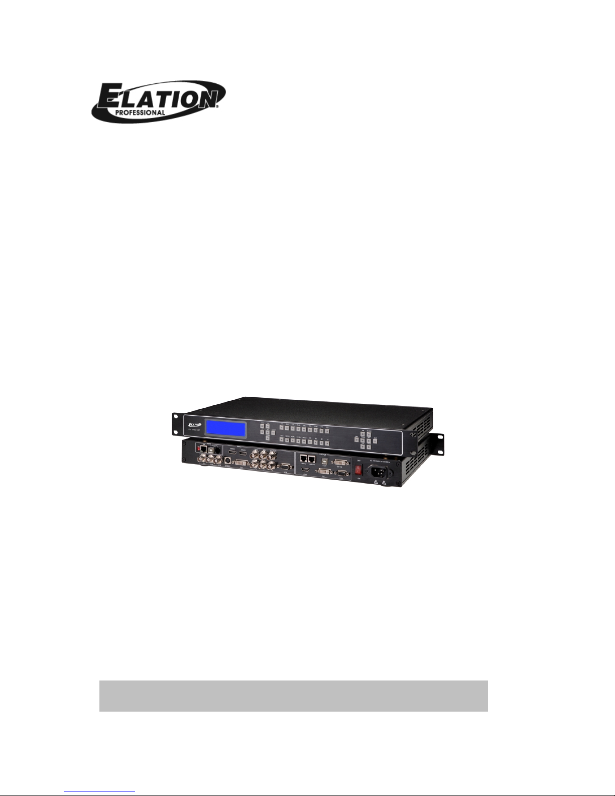
EPV IMAGE VSC
VIDEO PROCESSOR USER MANUAL

Elation Support
Thank You for Purchasing the EPV IMAGE VSC
Thank you for your purchasing the Elation Professional EPV IMAGE VSC Scaler and
LED wall control system. Please read the instructions in this manual carefully and
thoroughly before attempting to operate this unit. These instructions contain
important information regarding safety during use and maintenance. Please fill
out and return the enclosed warranty card to validate your purchase.
Customer Service
Elation provides a toll free customer support line, to provide set up help and to
answer any question should you encounter problems during you set up or initial
operation. You may also visit us on the web at www.elationlighting.com for any
comments or suggestions.
All returned service items whether under warranty or not, must be freight pre-paid
and accompany a Return Authorization (RA) number. The RA number must be
clearly written on the outside of the return package. Items returned without a RA
number clearly marked on the outside of the package will be refused and returned
at customer’s expense. You may obtain a RA number by contacting customer
service.
A brief description of the problem as well as the RA number must be written down
on a piece of paper and included in the shipping container. If the unit is under
warranty, you must also provide a copy of your proof of purchase invoice.
Customer Service hours are Monday through Friday 8:00 a.m. - 5:00 p.m. Pacific
Standard Time.
Toll Free: (866) 245-6726
Phone: (323) 582-3322
Fax: (323) 832-9142
Information: info@elationlighting.com
Sales: sales@elationlighting.com
Support: support@elationlighting.com
Forum: forums.elationlighting.com/eve

2-Year Limited Warranty
Elation® hereby warrants, to the original purchaser, Elation Professional®
products to be free of manufacturing defects in material and workmanship for a
period of 2 Years (730 days) on all internal parts, components, and labor. This
warranty shall be valid only if the product is purchased within the United States
of America, including possessions and territories. It is the owner’s
responsibility to establish the date and place of purchase by acceptable
evidence, at the time service is sought.
For warranty service, send the product only to the Elation factory. All shipping
charges must be pre-paid. If the requested repairs or service (including parts
replacement) are within the terms of this warranty, Elation will pay return
shipping charges only to a designated point within the United States except
Hawaii or Alaska. If the entire instrument is sent, it must be shipped in its
original package. No accessories should be shipped with the product. If any
accessories are shipped with the product, Elation shall have no liability
whatsoever for loss of or damage to any such accessories, nor for the safe
return thereof.
This warranty is void if:
• The serial number has been altered or removed
• The product is modified in any manner which Elation concludes, after
inspection, affects the reliability of the product
• The product has been repaired or serviced by anyone other than the
Elation factory unless prior written authorization was issued to purchaser
by Elation
• The product is damaged because not properly maintained as set forth in
the instruction manual
This is not a service contract, and this warranty does not include maintenance,
cleaning or periodic check-up. During the period specified above, Elation will
replace defective parts at its expense, and will absorb all expenses for warranty
service and repair labor by reason of defects in material or workmanship. The
sole responsibility of Elation under this warranty shall be limited to the repair of
the product, or replacement thereof, including parts, at the sole discretion of
Elation. All products covered by this warranty were manufactured after
January 1, 1990, and bear identifying marks to that effect.
Elation reserves the right to make changes in design and/or improvements upon
its products without any obligation to include these changes in any products
theretofore manufactured.

No warranty, whether expressed or implied, is given or made with respect to
any accessory supplied with products described above. Except to the extent
prohibited by applicable law, all implied warranties made by Elation in
connection with this product, including warranties of merchantability or fitness,
are limited in duration to the warranty period set forth above. And no
warranties, whether expressed or implied, including warranties of
merchantability or fitness, shall apply to this product after said period has
expired. The consumer’s and or Dealer’s sole remedy shall be such repair or
replacement as is expressly provided above; and under no circumstances shall
Elation be liable for any loss or damage, direct or consequential, arising out of
the use of, or inability to use, this product.
This warranty is the only written warranty applicable to Elation Products and
supersedes all prior warranties and written descriptions of warranty terms and
conditions heretofore published.
Revision
Format
Time
ECO#
Description
Principal
1.0
2010-12-23
0000
Release
Lisa

CONTENT
1.0 Safety ........................................................................................... 1
2.0 Specification................................................................................... 1
2.1 Specification/Parameters ............................................................ 2
3.0 Connection..................................................................................... 4
3.1 EPV IMAGE VSC Back Panel......................................................... 5
3.2 How to install............................................................................ 7
4.0 Front Panel Keyboard Operation ........................................................ 7
4.1 EPV IMAGE VSC Operator Guideline.............................................. 8
4.2 Video Processor Menu ................................................................ 9
5.0 Communication Software Guideline.................................................. 14
5.1 Install Software....................................................................... 14
5.2 Run EPV IMAGE VSC Console..................................................... 18
6.0 FAQ............................................................................................. 27
6.1 No output in target display........................................................ 27
6.2 VGA input could not work with EPV IMAGE VSC Console ................ 27
6.3 DVI input could not work with EPV IMAGE VSC ............................ 27
6.4 Component input could not work with EPV IMAGE VSC.................. 28
6.5 User settings can not save ........................................................ 28
6.6 Can’t update main board software.............................................. 28
6.7 Display SDI1 or SDI2 in dual display mode.................................. 29
6.8 HDMI display shows blue screen ................................................ 29
6.9 Can’t be saved ALPHA value...................................................... 29
7.0 Quick Start................................................................................... 30
7.1 Single-screen control ............................................................... 30
7.2 Set dual screen fade ................................................................ 32
7.3 Displaying subtitles and LOGO ................................................... 33
7.4 How to control processor with console software by USB?............... 38
7.5 How to Use LINSN Ledset software? ........................................... 42
8.0 Appendix ..................................................................................... 44
8.1 AppendixⅠDownload the main board software............................. 44
8.2 Appendix II Download the IP software ........................................ 53
8.3 Appendix Ⅲ How to add tasks................................................... 55
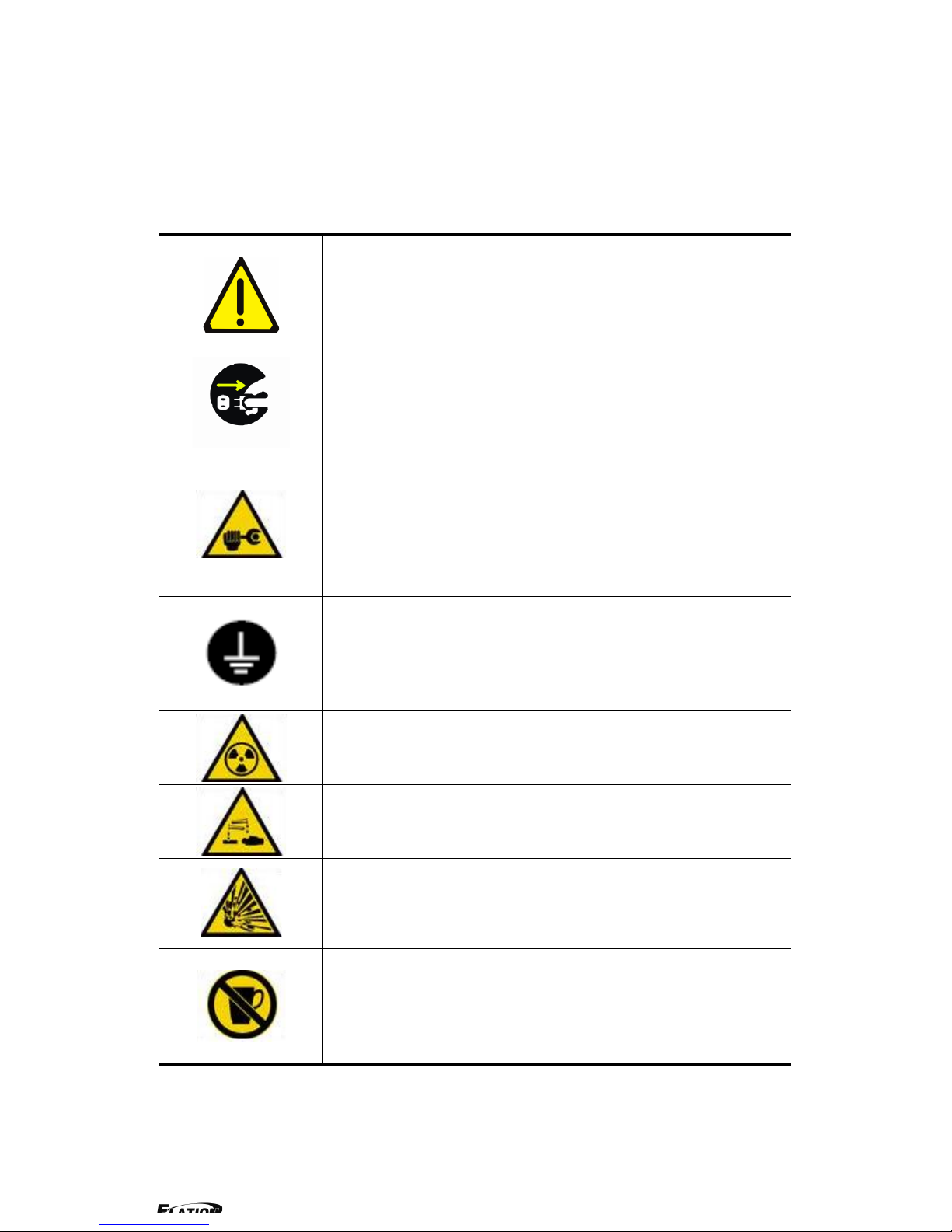
1.0 Safety
The general safety information in this summary is for operating person. Any
requirement, please feel freely to contact our service engineer.
Power Source
This product is intended to operate from a power source
between 85~265 volts rms . This product is only workable under
correct power condition, which is already mark on the back panel
of the power.
High Voltage
There are many high voltage components inside.
Do not Remove Covers and Panels
Do not remove Covers in any conditions. There are not any
spare components inside for maintenance, so do not maintain
this product by userrselves, any requirement, please feel free to
contact our service engineer. Keep heavy device from power
cord.
Grounding the Product and Use the Proper Fuse
This product is grounded through the grounding conductor of
the power cord. To Avoid electrical shock, plug the power cord
into a properly wired receptacle before connecting to the product
input or output terminals.
Keep away from Magnet, Motor, TV and Transformer.
Guard Against Damp
Keep using inside clean and dryness environment, once the
device get wet, must remove power cord right now.
Keep away Exploder
Do not operate the device inside dangerous and easy
explosive gas, which it may make fire, blast or something without
expectation.
Keep away Pour Liquid and Fragment
It is forbid to pour liquid, metal fragment or anything else
inside this device to avoid fire and other accident. Once that
happens, must remove power cord and try to make it clean
before power on again.
2.0 Specification
EPV IMAGE VSC series video processors are designed by the latest high
performance image processing technology. EPV IMAGE VSC can handle
following video without limit, in c l ud e CVBS(Composite)、S-Video ( YC )、YCbCr
、YPbPr、RGBHV(VGA)、DVI-D、HDMI、SDI(SD-SDI、HD-SDI) and VOIP
(Copper RJ45).
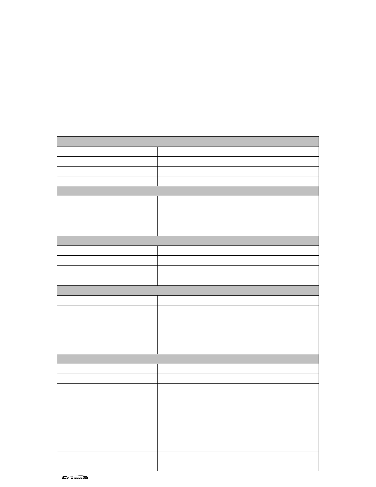
2.1 Specification/Parameters
Composite BNC Input
Number of Inputs
3
Supported Standards
PAL/NTSC
Signal Level
1Vpp±3db (0.7V Video+0.3v Sync ) 75ohm
Multiplex
YCbCr
S-video DIN4 Input
Number of Inputs
1
Supported Standards
PAL/NTSC
Signal Level
Y:1Vpp±3dB (0.7V Video+0.3v Sync ) 75ohm
U/V:0.7Vpp±3dB 75ohm
YPbPr BNC Input
Number of Inpus
BNC*3
Supported Standards
analog HD input
Signal Level
Y:1Vpp±3dB (0.7V Video+0.3v Sync ) 75ohm
Pb/Pr:0.7Vpp±3dB 75ohm
VGA DB15 Input
Number of Inputs
1
connetor
Standard DB15 socket
Supported Standards
VGA-UXGA
Signal Level
R、G、B、Hsync、Vsync:0 to1Vpp±3dB (0.7V
Video+0.3v Sync ) 75 ohm
black level:300mV Sync-tip:0V
DVI Input
Number of Inputs
1
Connector
Standard DVI-I socket
Supported Standards
SMPTE:625/25 PAL, 525/29.97 NTSC, 625/50p
PAL, 525/59.94p NTSC, 1080i50,
1080i59.94/60, 720p50 720p59.94/60
VESA : 800×600×60Hz , 1024×768×60Hz ,
1280×768×60Hz , 1280×1024×60Hz ,
1600×1200×60Hz , 1920×1080×60Hz ,
1920×1080×50Hz
Signal Level
TMDS pwl,single pixel input,165MHz bandwidth
Standard
DVI 1.1
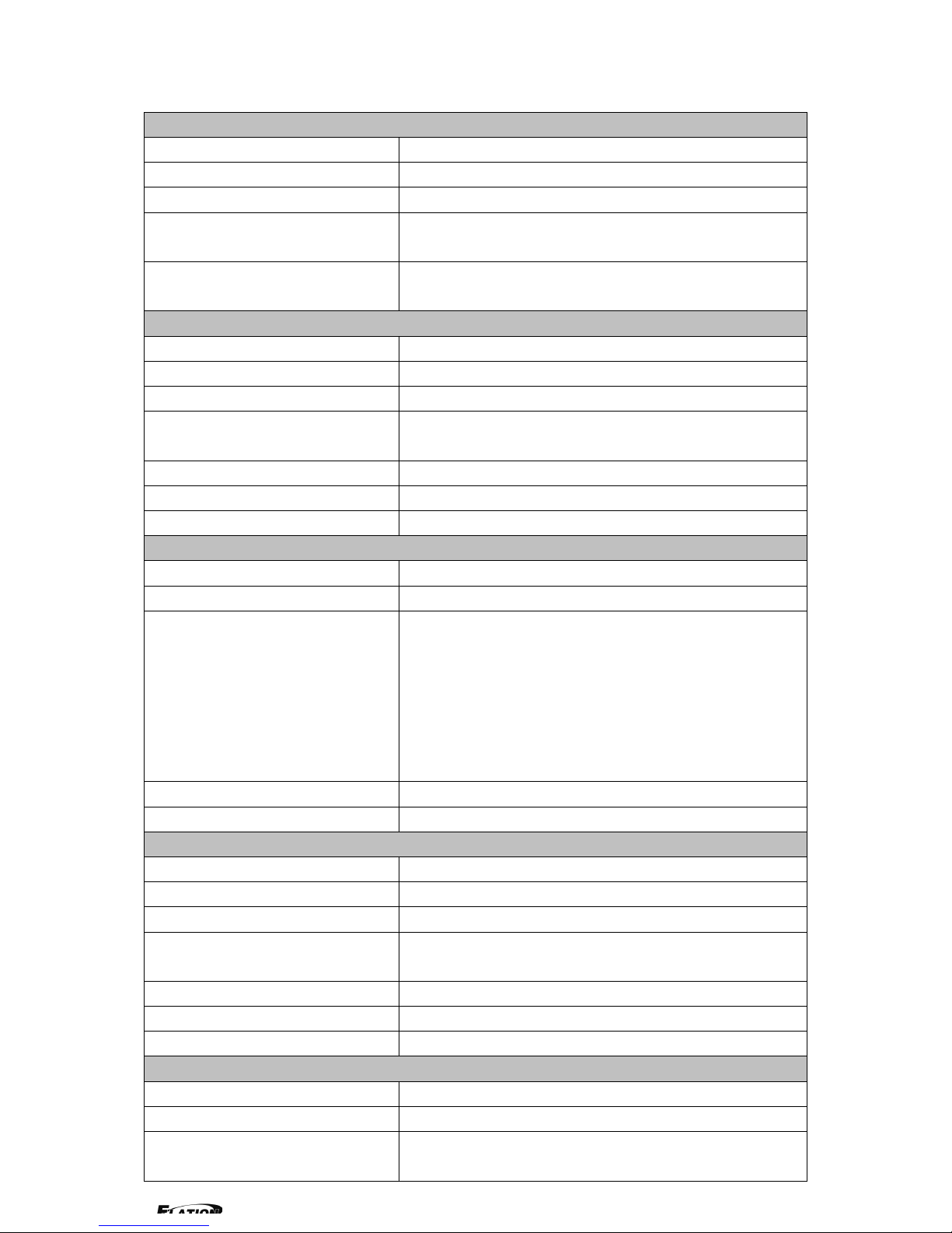
SDI Input
Number of Inputs
2
Connetor
BNC
Data Rate Range
19.4Mbps~1.5Gbps
Supported Standards
ITU-R BT.656,ITU-R BT.601,SMPTE 259M,
SMPTE 292, SMPTE 297
Equalization)
Belden 1694A 100M HD1.485G , 350m SD
270Mbps
SDI Loop-out
Number of Loop-Throughs
1
Signal Level
800mV±10%
DC Offset
0V±0.5V
Rise/Fall Time
HD1.485Gbps<270 ps ; SD 270 Mbps 0.4
ns~1.5ns
Overshoot
<10%
Timing Jitter
SD<0.2UI;HD<1.0UI
Alignment Jitter
<0.2UI
HDMI Input
Number of Inputs
2
Connector
HDMI (standard type A interface)
Supported Standards
SMPTE:625/25 PAL, 525/29.97 NTSC, 625/50p
PAL, 525/59.94p NTSC, 1080i50,
1080i59.94/60, 720p50 ,720p59.94/60
VESA : 800×600×60Hz , 1024×768×60Hz ,
1280×768×60Hz , 1280×1024×60Hz ,
1600×1200×60Hz , 1920×1080×60Hz ,
1920×1080×50Hz
Signal Level
TMDS pwl,single pixel input,165MHz bandwidth
Standard
HDMI 1.3
SDI Loop-out
Number of Loop-Throughs
1
Signal Level
800mV±10%
DC Offset
0V±0.5V
Rise/Fall Time
HD1.485Gbps<270 ps ; SD270 Mbps 0.4
ns~1.5ns
Overshoot
<10%
Timing Jitter
SD<0.2UI;HD<1.0UI
Alignment Jitter
<0.2UI
DVI Output
Number of Inputs
1
connetor
Standard DVI-I interface
Supported Resolution
800×600×60Hz , 1024×768×60Hz ,
1024×768×75Hz , 1280×768×60Hz ,

1280×1024×60Hz , 1440×900×60Hz ,
1400×1200×60Hz , 1600×1200×60Hz ,
1920×1080×60Hz , 1920×1200×60Hz ,
2048×1152×60Hz
Signal Level
TMDS pwl,165MHz bandwidth
VGA Output
Number of Inputs
1
connetor
Standard DB15 socket
Supported Resolution
800×600×60Hz , 1024×768×60Hz ,
1024×768×75Hz , 1280×768×60Hz ,
1280×1024×60Hz , 1440×900×60Hz ,
1400×1200×60Hz , 1600×1200×60Hz ,
1920×1080×60Hz , 1920×1200×60Hz ,
2048×1152×60Hz,2048×1536×60Hz
Signal Level
R、G、B、Hsync、Vsync:0 to1Vpp±3dB (0.7V
Video+0.3v Sync ) 75ohm
black level:300mV Sync-tip:0V
HDMI Output
Number of Outputs
1
Connetor
HDMI (standard type A interface)
Supported Standards
800×600×60Hz , 1024×768×60Hz ,
1024×768×75Hz , 1280×768×60Hz ,
1280×1024×60Hz , 1440×900×60Hz ,
1400×1200×60Hz , 1600×1200×60Hz ,
1920×1080×60Hz , 1920×1200×60Hz ,
2048×1152×60Hz
Signal Level
TMDS pwl,165MHz bandwidth
Function
Source Switch
Support every signal with alpha key operation
PIP
PIP for SD with HD and HD with HD
Alpha Key
support
Extras
Communication
RS232 TCP/IP
Power Supply
85-264V 2A IEC-3
Working Environment
0°C~45°C
Stored Environment
10% to 90%
Product Warranty
1year
Note:
Specifications are subject to change without notice.
3.0 Connection
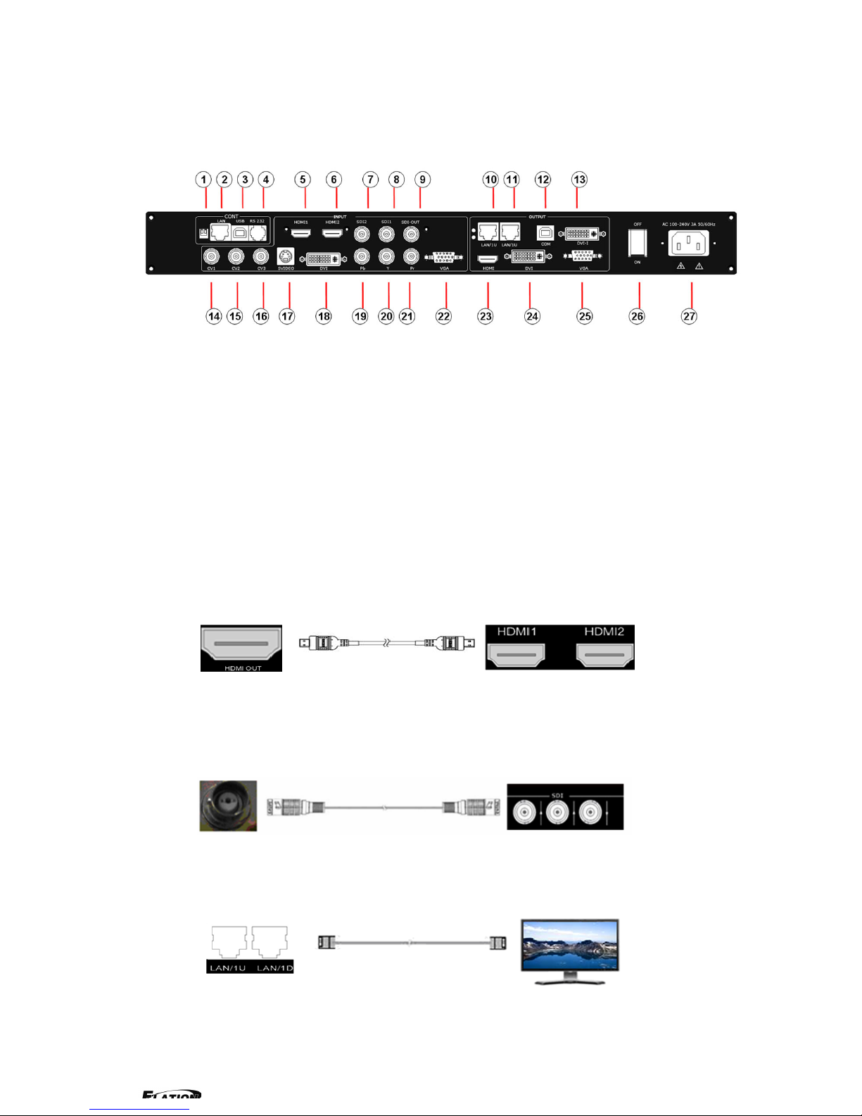
3.1 EPV IMAGE VSC Back Panel
1、Dial the code switch;
2 、 10/100M interface (copper RJ45). Used to connect the computer by
568B-568A twist-pair
3、USB interface,Used to connect the computer
4、RS232 interface (RJ11) for EPV IMAGE VSC processor. Used to connect the
computer;
5-6、HDMI i n pu t interface。Input the signal from HD player, DVD, computer, and
so on.
7-8、SDI Input BNC, used to support SD/HD SDI input。Input the video signal
from the HD player, HD projector. It can connect to the 7 or 8 interface on the
next EPV IMAGE VSC,using the 75ohm BNC.
9、SDI loop out BNC, used to loop input SDI signal to next SDI player.
10-11、Gigabit copper port, connect to LED screen.
12、Gigabit Transmitter card USB control interface;
13、Gigabit Transmitter card DVI input,connect to DVI output of EPV IMAGE
VSC;
(This Connection does not support hot-plugging)
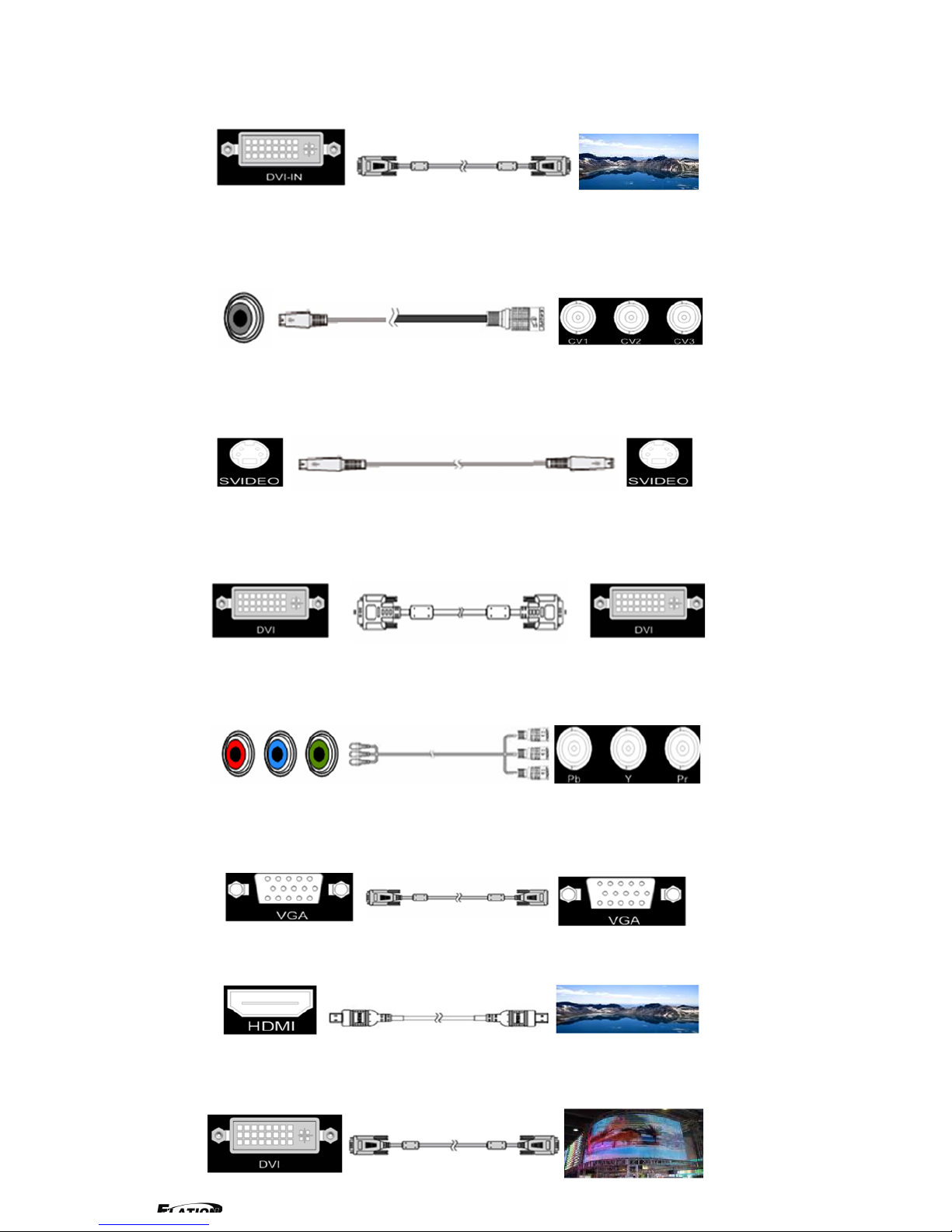
14-16、Composite input interface,Composite BNC. Used to input composite
signal (PAL, NTSC, SECAM compatible);
17 、 S-Video DIN 4, used to input S-Video signal ( PAL, NTSC, SECAM
compatible);
18、DVI input interface。Input the video signal from computer, DVI signal
generator. Connect to the same DVI interface on VSP;
(This Connection does not support hot-plugging)
19-21、R/Pr G/Y B/Pb BNC, used to support SD/HD progressive input, up to
1080p60;
22、VGA input interface, DB-15, used to support Analog RGB input; connect to
the VGA interface on VSP;
23、HDMI output, use to connect with HDMI monitor or HDMI player;
24、DVI output,connect to the monitor or LED display with DVI interface.
(This Connection does not support hot-plugging)
25、VGA output interface, connect to the monitor, projector and so on;
26~27、Switch and power. It must use IEC-3 power line. Always ground to avoid
electric shock.
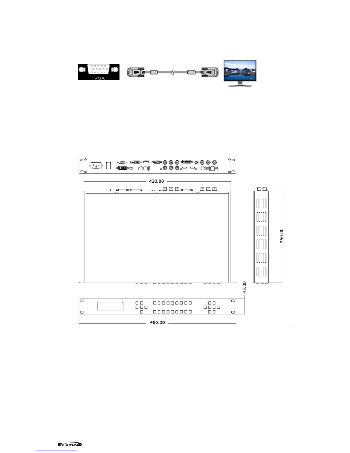
3.2 How to install
EPV IMAGE VSC frame size
4.0 Front Panel Keyboard Operation
Insert power cord and push power to ON position. LCD module on the front
panel will show ELATION LIGHTING and go into self verification before it load
last setting config and send processed image to the target monitor. For the first
setup, CV1 input is default source. With front panel keyboard, user can operate
VSP with menu display on LCD module.
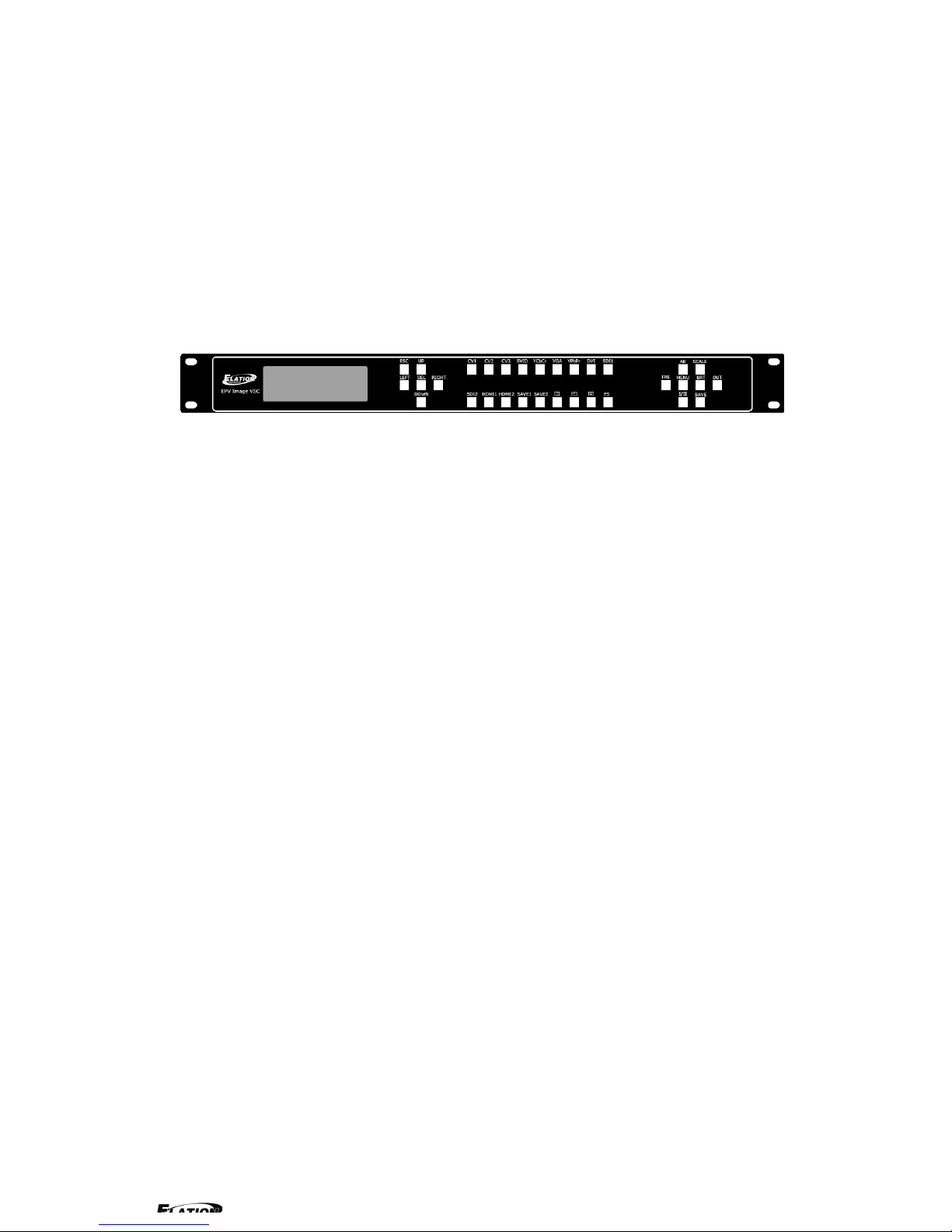
4.1 EPV IMAGE VSC Operator Guideline
EPV IMAGE VSC front panel as following:
1、LCD Module;
2、Keyboard:
ESC: push to exit from current choice item;
SEL: push to confirm the current choice item;
UP: push to select up items;
DOWN: push to select down items;
LEFT:push to select left items;
RIGHT:push to select right items;
CV1:switch to composite 1 input;
CV2:switch to composite 2 input;
CV3:switch to composite 3 input;
SVID:switch to s-video input;
YCbCr:switch to standard definition input;
VGA: switch to analog RGB input;
YPbPr: switch to high definition component;
DVI: Switch to DVI input;
SDI1:switch to SDI1 input;
SDI2:switch to SDI 2 input;
HDMI1:switch to HDMI 1 input;
HDMI2:switch to HDMI 2 input;
SAVE1:switch to use the user-defined mode 1;

SAVE2:switch to use the user-defined mode 2;
PBP:switch to show two pictures beside on beside;
PIP:switch to show picture in picture on the screen. CV1 is the default
small picture on the top left corner, DVI is the default picture full
screen;
POP:switch to show picture out picture on the screen;
FS:switch to selet full screen or zoom view, just for single picture
mode;
MENU: push to go to main menu;
FRE:push to freeze the video image or live again
(FreezeLiveFreeze)
AB: push to switch between front picture and back picture if works in
dual channel mode with alpha key, front picture will alpha key in step by
step and back picture key out step by step;
SCALE: push to go to between scalezoomcropscale mode;
BRT:push t o ad ju s t t he b ri gh t ne ss an d th e c o nt ra s t r at i o, push to e nt er
to the relevant Menu, and then push the UP and DOWN to adjust the
brightness and the contrast ratio;
OUT: push to select the output format by using the UP and DOWN;
I/II: push to set single or dual channe;
SAVE: push to save current config;
4.2 Video Processor Menu
System menu as follows;
Fig. 1
The first line shows EPV IMAGE VSC.
Push the right and left direction key to select the left or right menu. Before
the menu item, if there is a * sign, means the menu item has been selected;
you can push the Select key to enter it.
The on the right means you can select the menu items by pushing the up
and down direction key.
User can check the information of the equipment in “Dev Info” menu
(including the manufacturer、serial-number );
User can get more service and support according to the serial-number.
User can check current input and output sources in Dev Info menu also.
Touch UP/DOWN to check System time
User can do a Factory Settings in Recall menu, after successful reset you will
see the menu as follows:
Push the MENU to enter the main menu, and then push up and down
direction key, the menu as follows:
Push the LEFT/RIGHT to select the relevant submenu.
LANGUAGE submenu as follows:
System time:
2009-08-17 15:12:35
Factory reset was completed !
Input: CV1 1024x768x60
Output: CV2 1024x768x60
ELATION LIGHTING
>SN:3204
> EPV701
*Language Alpha ↑
> EPV701
*Dev Info Recall ↓
Push UP/DWON to enter Alpha setup, user can set value from 0 to 100,
0 means video or graphic would be disappear and 100 means normal;
Port A and Port B stand for two channel picture;
Push OUT to enter the Output menu, push the UP or DOWN to select
different output resolution, push OK to confirm the output resolution.
Advance submenu as follows:
Added adjustable feature of DE;
Press UP/DOWN and select the menu as shown in Figure 1:
Figure 1
Press LEFT/RIGHTand select XY_Pos to enter the submenu of adjusting
effective area;
XY_Pos:The sub-menu of which is used to ad j us t t h e p os i ti on o f o ve r al l e f fe cti ve
area shown on the screen or monitor.
H_BLANK: The overall effective area can be moved around by adjusting the
value of H_BLANK.
V_BLANK:The overall effective area can be moved up and down by adjusting the
value of V_BLANK.
Added adjustable feature of DE,support the following resolution:
"800x600x60 Hz "、"1024x768x60 Hz "、"1024x768x75 Hz "
Note:
"1280x1024x60 Hz "、"1400x1050x60 Hz "、"1600x1200x60 Hz "
H_BLANK
*HS: 46
V_BLANK
*VS: 38
> EPV701
*Advance XY_Pos ↑
Screen parameter:
Hsize: 1024
*Alpha
Port A Value: 100
*LANGUAGE
>Chinese English

Step:user can set the step of scale;
HSize:set the horizontal size of the image;
VSize:set the vertical size of the image;
HPos:set the horizontal position of the image;
VPos:set the vertical position of the image;
User can set size and position of the screen simply, Mainly applies to LED
screens users. After setting screen parameter, the user choice PIP or PBP
operation, display picture can directly shows on corresponding screen。
Push the/to enter Single or Dual channel menu , push the UP / DOWN to
select the single or dual channel, push SEL to confirm the single channel or
dual channel work state;
Select the input channel, push the UP/DOWN, and SEL to confirm the
different input channel. User can also push the channel name on the
keyboard to go into the input channel.
AB in EPV IMAGE VSC is for two image Alpha in and out.
OR:
Screen parameter:
Hsize: 1024
Setup
A on B
Setup
Single
Source Select
>CV1
Setup
Dual
Output
>1024x768x60
Push SCALE to set the size and position of the image, push UP/DOWN and
SEL to confirm the relevant items;
Step:user can set the step of scale;
HSize:set the horizontal size of the image;
VSize:set the vertical size of the image;
HPos:set the horizontal position of the image;
VPos:set the vertical position of the image;
Push the FRE to freeze the live image or live the freeze image.
OR:
Push BRT to set the brightness and the contrast ratio:
OR:
Push SAV E and th e n pus h SAVE 1 or SA V E2 to save the operation to SAVE1 or
SAVE2;Push SAVE1 or SAVE2 to execute relative operation after user save
the operation sucessfully.
Select Save Mode !
Push Esc To Exit
> EPV701
Contrast 50 ↑
> EPV701
Brightness 50 ↓
Live Frame
Once gain for live
Freeze Frame
Once gain for live
Setup
A on B
Scale
> Step 10
5.0 Communication Software Guideline
EPV IMAGE VSC video processor is very easy to be configured with user
friendly communication software, support drag and drop operation for edit and
display. Also can customized with schedule function.
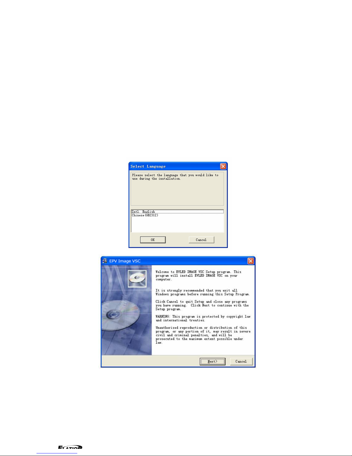
5.1 Install Software
Dual click EPV IMAGE VSC.exe to install, select Chinese or English version
for use,after click “select ”to next dialog.
If user agree to install this software, please click next to go on, else click esc to
exit this install.
And in next dialog is the user agreement of the software, click agree to go on
and refuse to exit.
 Loading...