

EPV762 MH
Elation Professional
6122 S Eastern Ave
Los Angeles, Ca 90040
www.elationlighting.com

Contents
1. Introduction……………………………………………………………………………………………………………..…….1
1.1. Brief Instruction …………………………………………………………………………………….…………….1
1.2. Package Accessories…………………………………………………………………….……………………….1
2. Features………………………………………..……………………………………………..…………….………………….1
3.TECHNICAL SPECIFICATIONS…………………………………….………………..……….……………………….2
4 .Overview ………………………………………………………………………………………………………………………. 3
5 .Safety Info …………………………………………………………………………………………………………………… 4
5.1. Important Safety Caution………………………………………………………………………………….. 4
5.2. GENERAL GUIDELINES………………………………………………………………………….…………… 4
6 .Installation Instruction………………………………………………………………………………………………….. 5
7 . DMX-512 control connection……………………………………………………………………………………….. 6
8 .Connection of PC and Controller…………………………………………………………………………………… 7
9 . DMX-512 connection with DMX terminator……………………………………………………………….. 7
10 . Projector DMX starting address selection………………………………………………………………… 8
11 . Control Board……………………………………………………………………………………………………………. 8
12 . INSTRUCTIONS ON USE…………………………………………………………………………………………... 15
Software fractional introduce
13.Installation and Application of LED Managing Tool …………………………………………………… 17
13.1. Features ………………………………………………………………………………………………………….…. 17
13.2. Operating Environment ……………………………………………………………………………………. 17
13.3. Installation………………………………………………………..……………………………………………….. 17
13.4. Uninstallation……………………………………………………………………………………………………… 18
14.Use details …………………………………………………………………………………………………….…………. 18
14.1. Program composition.……………………………………………………………………………………... 18
14.2. Introduction of interface window ……………………………………………………………………. 19
14.3. Feature detail…………………………………………………..……………………………………………….. 20
14.4. Progress of Program production………………………………………………………………………. 25
15.Text display …………………………………………………………………………………………………….…………. 29
15.1. Play single-line window.…………………………………………………………………………………... 29
15.2. Play multi-line window ……………………………………………………………………………………. 30
15.3. Play Word/Excel…………………………………………………..…………………………………………….. 32
16.Image display ………………………………………………………………………………………………….…………. 33
16.1. New multimedia window.………………………………………………………………………………... 33
16.2. Set multimedia window …………………………………………………………………………………… 33
16.3. Open the play file…………………………………………………..………………………………………….. 33
16.4. Set the play image properties………………………………………………………………..…………. 34
17.Video display ………………………………………………………………………………………………….………….. 35
17.1. New multimedia window.……………………………………………………………………………….... 35
17.2. Set multimedia window ………………………………………………………………………………….. 35
17.3. Open play file…………………………………………………..……………………………………………….. 35

2
17.4. Set property of Video files………………………………………………………..…………..…………. 36
18.Table display ………………………………………………………………………………………………….………….. 36
18.1. New multimedia window.……………………………………………………………………………….... 36
18.2. Set multimedia window ……………………………………………………………………………………. 36
18.3. Insert & Edit table……………………………………………..…………………………………………….. 36
19.Web display ………………………………………………………………………………………………….………….. 38
19.1. New multimedia window.………………………………………………………………………………... 38
19.2. Set multimedia window …………………………………………………………………………………… 39
19.3. Open playing grogram file…………………………………………………..……………………………. 39
19.4. Set Web Properties…………………………………………………………..……………….…..…………. 39
20.Database display ………………………………………………………………………………………….………….. 40
20.1. New multimedia window.………………………………………………………………………………... 40
20.2. Set multimedia window …………………………………………………………………………………… 40
20.3. New Access Database………………………………………………..……………………………………. 40
20.4. Add ODBC drive database…………………………………………………………..……………….……. 43
21.Date & Time ……………………………………………………………………………………….………….………….. 44
21.1. New multimedia window.………………………………………………………………………………... 44
21.2. Set multimedia window …………………………………………………………………………………… 44
21.3. Add data/time…………………………………………………..…………………………..…………………. 44
21.4. Set data/time………………………………………………………..…………………..……………….……. 44
22.Eternal Program ……………………………………………………………………………….………….………….. 46
22.1. New multimedia window.………………………………………………………………………………... 46
22.2. Set multimedia window …………………………………………………………………………………… 46
22.3. Open external program…………………………………………………..………………………………. 46
22.4. Set external program window………………………………………..………………………….……. 47
23.Timer Display ……………………………………………………………………………….………….……………… 48
23.1. New multimedia window.………………………………………………………………………………... 48
23.2. Set multimedia window …………………………………………………………………………………… 48
23.3. New timer Display………………………………………………………………………………………………. 48
23.4. Set timer………………………………………..………………………………………….……………….……. 48
24.Instant messaging …………………………………………………………………………….………….………….. 49
24.1. New instant messaging.………………………………………………………………………………... 49
24.2. Set instant messaging …………………………………………………………………………………… 49
24.3. Play instant messaging………………………………………………………………………………………. 50
25.Video input display …………………………………………………………………………….………….………….. 51
25.1. New multimedia window.………………………………………………………………………………... 51
25.2. Set multimedia window …………………………………………………………………………………… 51
25.3. New external video……………………………………………………………………………………………. 51
26.Flash Display ……………………………………………………………………………..…….………….………….. 53
26.1. Make Flash effect text.…………………………………………………………………………….……... 53
26.2. Play Flash ……………………………………………………………………………………….………………… 54
27.Screen capture ……………………………………………………………………………….………….………….. 56
27.1. New multimedia window.………………………………………………………………………………... 56
27.2. Set multimedia window …………………………………………………………………………………… 56
27.3. New screen capture……………………………………………………………………………………………. 56
27.4. Set screen capture………………………………………..………………………….……………….……. 56
27.5. Record………………………………………………………………………….……………………………………. 57
27.6. Play video………………………………………..………………………………………….……………….……. 57
28.Time Display …………………………………………………………………………………….………….………….. 58
28.1. Open time repertoire.……………………………………………………………………………………... 58
28.2. Add time repertoire ……………………………………………………….………………………………… 58

3
28.3. Edit time repertoire……………………………………………………………………………………………. 60
28.4. Delet time repertoire……………………………………..………………………….……………….……. 60
28.5. Start time repertoire…………………………………………………….……………………………………. 60
28.6. Exit…………………………………………………..………………………………………….……………….……. 60
29.Environment Monitoring ………………………………………………………………….………..….………….. 61
29.1. Open Brightness Control Repertoire.………………………………………………………………... 61
29.2. New brightness control repertoire ……………………………………………………….………… 61
29.3. Edit brightness control repertoire………………………………………………..…………………. 62
29.4. Delete brightness control repertoire……………………………………….……………….……. 62
29.5. Restore fault brightness control repertoire……………………………………………………. 63
30.Software Setting …………………………………………………………………………….………..….………….. 63
30.1. Set basic properties of software.…………………………………………..………………………... 63
31.Hardware setting …………………………………………………………………………….………..….………….. 64
32.Screen control ……………………………………………………………………………….………..….………….. 64
32.1. Set brightneess/contrast/Color temprature.…………………………………………………... 64
32.2. Set Screen Location ………………………………………………………..…….…………………..…… 65
32.3. Close/Freeze screen…………………………………..……………….……………….……………………. 66
33.View Device Status …………………………………………………………………………………..….………….. 67
33.1. Open Device Status.……………………………………………………………………………………….... 67
34.View environment monitoring ……………………………………………………….………..….………….. 69
34.1. Open environment monitoring.…………………………………………………..…………………... 69
34.2. Set Environment monitoring factors ………………………………..…….…………………..… 69
35.FAQ ………………………………………………………………………………………………………….….………….. 71
1
1. Introduction
1.1 Brief Instruction
Thank you for having chosen this professional LED lighting.
You will see you have acquired a powerful and versatile device. For your own safety and
utilize all wonderful functions of our LED screen, please read this user manual carefully
before installing the device.
Every person involved with the installation, operation and maintenance of this device has
to
- be qualified
- follow the instructions of this manual
1.2 Package Accessories:
1. One XLR connection cable
2. One power cable
3. Reticle
4. One Safety rope
5. Two omega clamps
6. Manual
Please check carefully that there is no damage caused by transportation. Should there be
any, consult your dealer and don’t install this device.
2. Features
• Channel modes: 6 channels
• Pan/tilt movement: 8 bit and 16 bit resolution
For smooth and precise resolution
Pan: 540°/630° optional, Tilt: 265°movement
High speed of pan/tilt movement, speed of pan/tilt movement is adjustable
Scan position memory, auto reposition after unexpected movement
• Excellent effect: apply dynamic scanning technology, screen with strong brightness, and
fine contrast
• Slender and clear image, vivid and multiform video, smooth and living visual effects
• Neat structure: aluminium material, super-light-thin-strong, and good light
transmittance
• Easy installation and maintenance: light-thin-strong modular design to make easy
movement, installation and maintenance
• Good and stable quality: we use imported light-emitting materials, high-quality IC chip,
high-power and noise-free power supply to achieve perfect quality
• Flexible format: can be scheduled with any display mode
• Rich content: can display text, graphics, images, animation, video information
• Big capacity of info: unlimited information display
• 50,000 hours LED life
• Bule and white LCD display
• Auto-program: 7 pre-built programs can be selected
• Software-upload by optional accessory via DMX line

2
3. TECHNICAL SPECIFICATIONS
Pixels Placing:7.62MM
Pixels Density:17222dots/m2
View Angle:H145°/V110°
Video Output:DVI
Power supply:AC 100-240V~, 50/60Hz
Power consumption:320W
Unit Size:488 x 488mm
Net weight:24KG/ screen
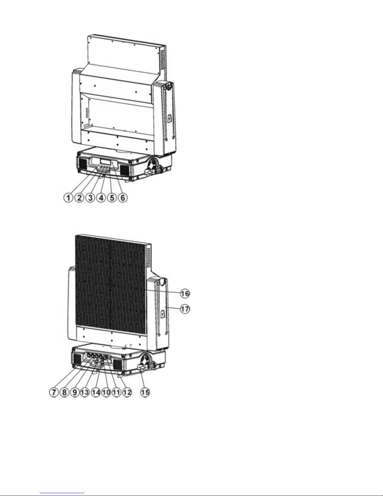
4. Overview
3
5. Safety Info
5.1 Important Safety Caution
1)LCD Display
2)Mode/esc Button
3)Menu UP Button
4)Menu DOWN Button
5)Enter Button
6)Microphone
7)5-Pin DMX in
8)5-Pin DMX out
9)3-Pin DMX in
10)3-Pin DMX out
11) Power in
12) Fuse
13)Signal out
14)Signal in
15) Carrying handle
16) LED CURTAIN
17)Yoke

4
This LED CURTAIN has left the factory in perfect condition. In order to maintain this
condition and to ensure a safe operation, it is absolutely necessary for the user to follow
the safety instructions and warning notes written in this user manual.
If the LED CURTAIN has been exposed to temperature changes due to environmental
changes, do not switch it on immediately. The arising condensation could damage the
LED CURTAIN. Leave the device switched off until it has reached room temperature.
Make sure operation after every piece of LED connected properly.
Make sure that the available voltage is not higher than stated at the end of this
manual.
Make sure the power cord is never crimped or damaged by sharp edges. If this would
be the case, replacement of the cable must be done by an authorized dealer.
Always disconnect from the mains, when the device is not in use or before cleaning it.
Only handle the power cord by the plug. Never pull out the plug by tugging the power
cord.
Please be aware that damages caused by manual modifications to the device are not
subject to warranty. Keep away from children and non-professionals.
If the external flexible cable or cord of this luminaire is damaged, it shall be exclusively
replaced by the manufacturer or his service agent or a similar qualified person in order
to avoid a hazard.
5.2 GENERAL GUIDELINES
This device is a lighting effect for professional use on stages, in discotheques,
theatres, exposition, etc.
This fixture is only allowed to be operated with the max alternating current which
stated in the technical specifications in the last page of this manual
Lay the LED screen carefully, avoid the heavy pressure on LEDs.
Fixtures cannot be installed on combustible substances, keep more than 50cm
distance with wall for smooth air flow, so there should be no shelter for fans and
ventilation for heat radiation.
Always fix the fixture with an appropriate safety cable if you use the quick lock cam in
hanging up the fixture, please make sure the 4 quick lock fasteners turned in the
quick lock holes correctly.
While choosing the installation-spot, please make sure that the device is not exposed
to extreme heat, moisture or dust.
When fixing the device on a raised-from-the- ground support, be sure to insert quicklock detain in the pre-arranged screw holes, and fix the device with an accessorial
safety cable.
Operate the device only after having familiarized with its functions. Do not permit
operation by persons not qualified for operating the device. Most damages are the
result of unprofessional operation.
Please use the original packaging if the device is to be transported.
For safety reasons, please be aware that device teardown are forbidden.
If this device will be operated in any way different to the one described in this manual,
the product may suffer damages and the guarantee becomes void.

5
6. Installation Instruction
a). The operating temperature of this device is -15o C ~ 50o C and moisture within
10%~95%, please use the device not exceed this range.
b). The installation of the effect has to be built and constructed in a way that it can hold
10 times the weight for 1 hour without any harming deformation.
c). Never stand directly below the device when mounting, removing or servicing the
fixture.
d). The operator has to make sure the devices are properly connected according to this
manual
Installtion Instruction:
a) Fixed the clamp on the bracket by tighten up the M12 screw on the bracket to the Ф13
hole in the middle of the bracket.
b) Insert the quick-lock fasteners of the first Omega holder into the respective holes on
the bottom of the device. Tighten the quick-lock fasteners fully clockwise.
c) Install the second Omega holder.
d) Pull the safety-rope through the holes on the bottom of the base and over the trussing
system or a safe fixation spot. Insert the end in the carabine and tighten the safety
screw.
6
Notice: this step is quite important to ensure that the fixture will not drop out
by the damage of the clamp.
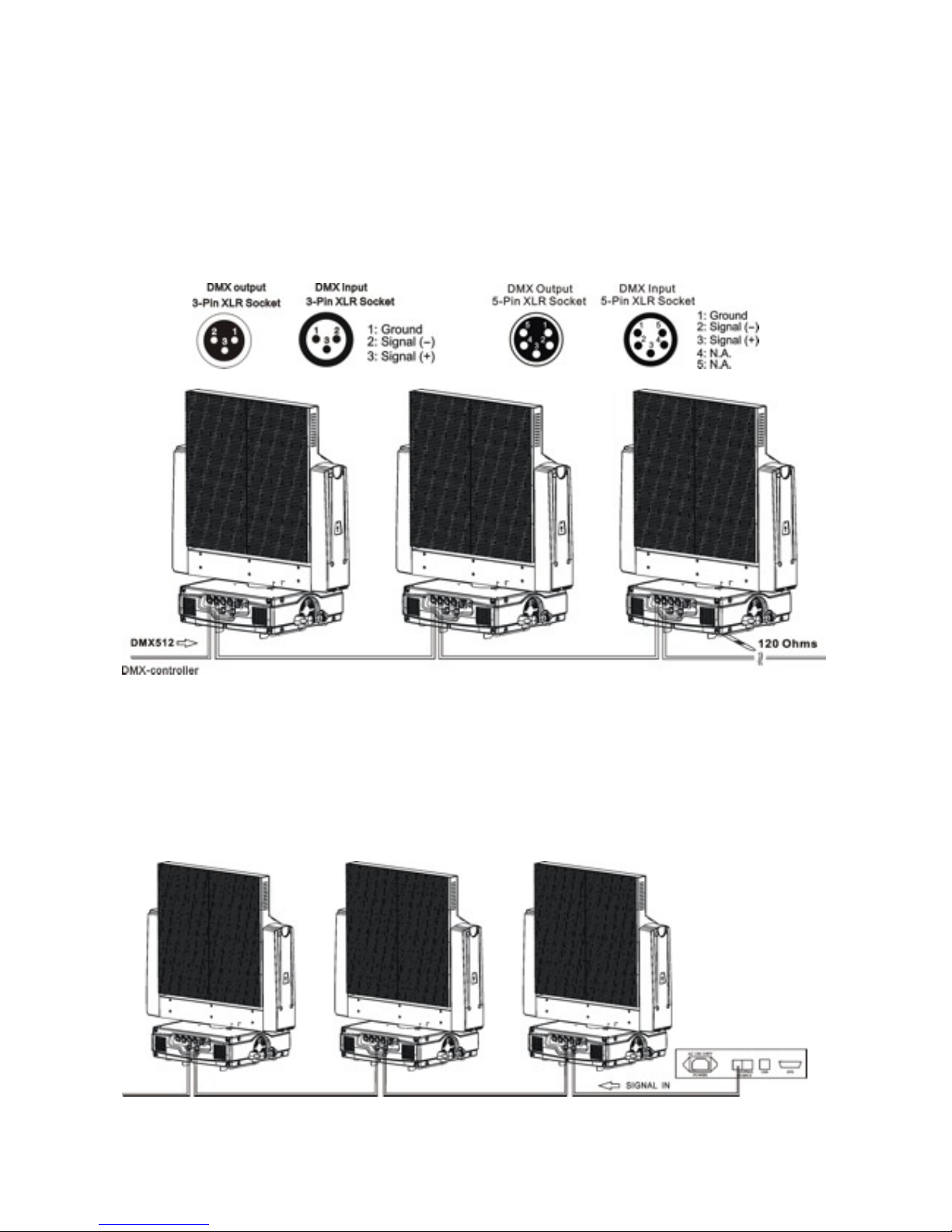
7. DMX-512 control and signal connection
DMX-512 control connection
Connect the provided XLR cable to the female 3-pin XLR output of your controller and the
other side to the male 3-pin XLR input of the moving head. You can chain multiple
Moving head together through serial linking. The cable needed should be two core,
screened cable with XLR input and output connectors. Please refer to the diagram below.
Starting address 1 Starting address 7 Starting address 13
Signal connection
For signal connection, please connect the signal cable end to led display transmitter first
outlet, a master card to connect to the led display of the engine signal inputs. from the
first screen of the signal output is connected to the second block display output, and so
on, until all display attached. The signal cable must be reticle connected to mother card
respectively, Please see the following signal connection picture:
7
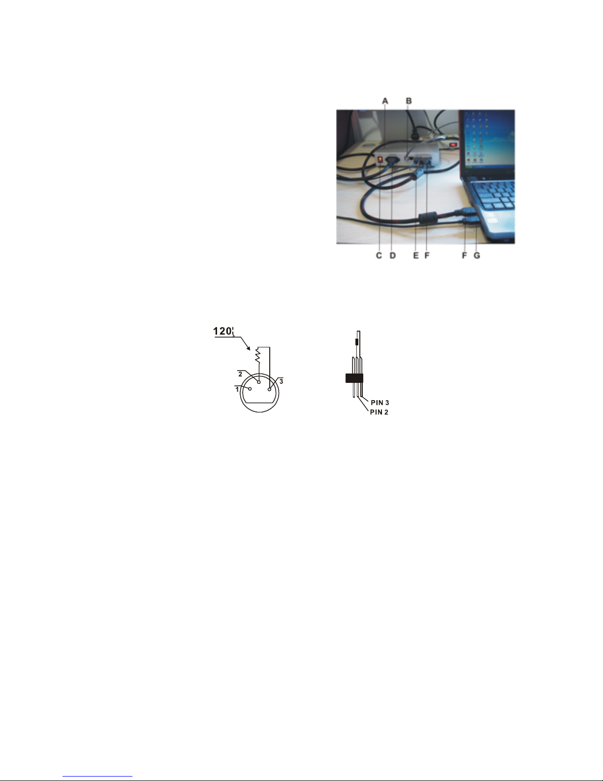
8. Connection of PC and Controller
Connect the video display controller and PC DVI connector with DVI cable, then connect
controller to PC USB connector with USB cable, controller’s output cable connect to
vertical input of LED screen, see following picture:
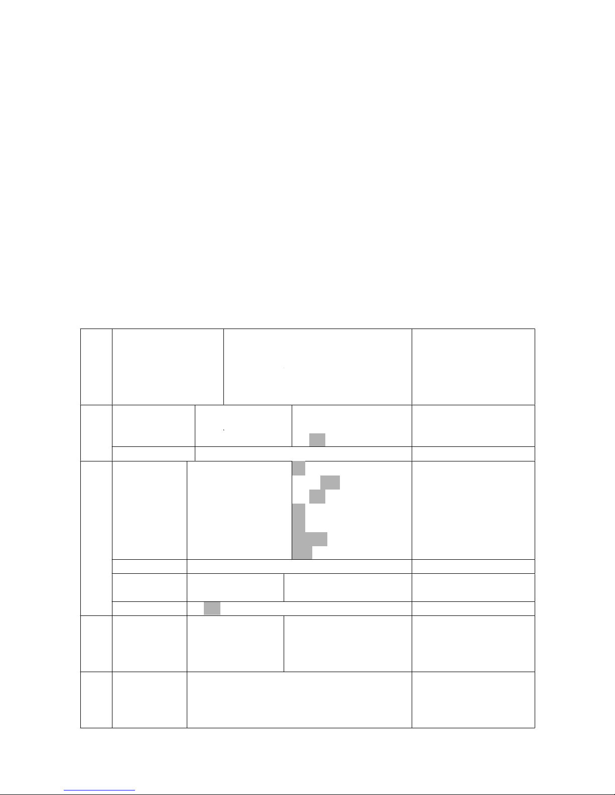
9. DMX-512 connection with DMX
terminator
For installations where the DMX cable has to run a long
distance or is in an electrically noisy environment, such
as in a discotheque, it is recommended to use a DMX
terminator. This helps in preventing corruption of the digital control signal by electrical noise. The
DMX terminator is simply an XLR plug with a 120 Ω resistor connected between pins 2 and
3,which is then plugged into the output XLR socket of the last fixture in the chain. Please see
illustrations below.
10. Projector DMX starting address selection
All fixtures should be given a DMX starting address when using a DMX signal, so that the correct
fixture responds to the correct control signals. This digital starting address is the channel number
from which the fixture starts to “listen” to the digital control information sent out from the DMX
controller. The allocation of this starting address is achieved by setting the correct number on the
display located on the base of the device.
You can set the same starting address for all fixtures or a group of fixtures, or make different
address for each fixture individually.
If you set the same address, all the units will start to “listen” to the same control signal from the
same channel number. In other words, changing the settings of one channel will affect all the
fixtures simultaneously.
If you set a different address, each unit will start to “listen” to the channel number you have set,
based on the quantity of control channels of the unit. That means changing the settings of one
channel will affect only the selected fixture.
In the case of the moving head, which is 6channels fixture, you should set the starting address of the
first unit to 1, the second unit to 7(6 + 1), the third unit to13 (6+ 7), and so on.
A. LED Screen Controller
B. Signal out cable
C. Power switch
D. Power in cable
E. USB cable
F. DVI cable
G .USB cable
8
11. Control Board
There are four keys on the control panel , which could be used to set the address, turn
ON/OFF, operating the program and reset.
[Mode/Esc] press this key to enter into edit mode. Press this key under the edit mode if
you want to return to previous menu. it will exit from edit mode 60 seconds after the last
keypress
[UP] screen will flash when pressing this key in normal mode, the adress value
will increasing. Keep pressing this key, the address value will increase rapidly. it will exit
from flash 60 seconds after the last keypress. Press this key under edit mode, you can
choose the function you want from the buttom up in the menu.
[DOWN] screen will flash when pressing this key in normal mode, the adress value
will idecreasing. Keep pressing this key, the address value will decrease rapidly. it will exit
from flash 60 seconds after the last keypress. Press this key under edit mode, you can
choose the function you want from the top down in the menu.
[ENTER] this key is functionless when in normal mode. Press this key under the edit
mode, it will enter into next menu.
Func
tion
Mod
e
Set Dmx Address
Value Display
Set To Slave
Auto Program
Music Control
A001~AXXX
PAN……
Slave1,Slave2,Slave3
Master / Alone
Master / Alone
DMX address setting
DMX value display
Slave setting
Auto program
Music control
Info
rmat
Time Information
Current Time
Total Run Time
Clear Total Time
XXXX(Hours)
XXXX(Hours)
ON/OFF
Power on running time
Fixture running time
Clear Fixture running tim
Info
rmat
ion
Software Version
Ver1.0
Software version of each IC
Pers
onali
ty
Status Settings
Address via DMX
No DMX Status
Pan Reverse
Fine Resolution
Feedback
Movement Speed
Mic Sensitivity
ON/OFF
Initial/Hold/Auto/Music
ON/OFF
ON/OFF
ON/OFF
Speed 1~ 4
70%, 0~99%
Add. via DMX
Auto run if no DMX
Pan Reverse movement
Fine resolution switch
Movement Feedback switch
Movement Mode Select
Sensitivity of Mic.
Pers
onali
ty
Display Setting
Shutoff Time
Display shutoff time
Pers
onali
ty
Initial Effect
PAN:PAN =XXX
:
Initial effect position
Pers
onali
ty
Reset Default
ON/OFF
Restore factory sett.
Effe
ct
Adju
st
Calibrate Values
--Password--
PAN:
Password=XXX
PAN =XXX:
Calbrate and adjust the
effects to standard/right
position Password “050”
Rese
t
Func
tion
Reset All
Reset Pan&Tilt
Reset all motors
Reset Pan
9
Select Programs
Auto Pro Part 1
Auto Pro Part 2
Auto Pro Part 3
Program 1 ~ 10 Program 1
Program 1 ~ 10 Program 2
Program 1 ~ 10 Program 3
Select programs to be run
Edit
Prog
Edit Program
Program 1
:
Program 10
Program Test
Step 01=SCxxx
Step 64=SCxxx
(“STEP XX”)
Testing program
Program in loop
Save and exit
Edit
Prog
ram
Edit Scenes
Edit Scene 001
~ Edit Scene 250
Pan,Tilt,……
--Secne Time--
Input By Outside
Pan=xxx……
TIME=xx.xs
Save and automatically
return
manual scenes edit
Edit
Prog
ram
Rec. Controller
XX~XX
Automat. scenes rec
Default settings shaded
Function Mode
DMX Address Setting
With this function, you can adjust the desired DMX-address via the Control Board.
• Select “Set DMX address” via the encoder.
• Press the encoder, adjust the DMX address by turning the encoder.
• Press the encoder to confirm.
• Press the Mode/Esc-button in order return to the main menu.
Display the DMX 512 value of each channel
With this function you can display the DMX 512 value of each channel. The display
automatically shows the channel with a value changing.
Slave Setting
With this function, you can define the device as slave.
Auto Program
With this function, you can run the internal program. You can select the desired program
under “Select program”. You can set the number of steps under “Edit program”. You can
edit the individual scenes under “Edit scenes”. With this function, you can run the
individual scenes either automatically, i.e. with the adjusted Step-Time.
Music control
With this function, you can run the internal program sound-controlled.

10
Information
Time information
Current Time
With this function, you can display the temporary running time of the device from the last
power on. The display shows “XXXX”, “XXXX” stands for the number of hours. The counter
is resetted after turning the device off.
Total Run Time
With this function, you can display the running time of the device. The display shows
“XXXX”, “XXXX” stands for the number of hours.
Clear Total Time
With this function, you can clear total run time of the fixture. The display shows “ON” or
“OFF”, Press “Enter” to confirm.
Software version
With this function, you can display the software version of the device.
• Select “Software version” by turning the encoder.
• Press the encoder, the display shows “V-X.X”, “X.X” stands for the version number, e.g.
“V-1.3”
• Turn the encoder in order to read the version of every individual IC.
• Press the Mode/Esc-button in order to return to the main menu.
PERSONALITY
Status Settings
Address Via DMX
With this function, you can adjust the desired DMX-address via an external controller.
• Select “Address via DMX” by turning the encoder.
• Press the encoder, the display shows “ON” or “OFF”.
• Turn the encoder to select “ON” if you wish to enable this function or “OFF” if you don’t.
• Press the encoder to confirm.
• Press the Mode/Esc-button in order to return to the main menu.
• On the controller, set the DMX-value of channel 1 to "7".
• Set the DMX-value of channel 2 to "7"or "8". When set to "7" you can adjust the starting
address between 1 and 255. When set to "8" you can adjust the starting address between
256 and 511.
• Set the DMX-value of channel 3 to the desired starting address. If you want to set the
starting address to 57, set channel 1 to "7", channel 2 to "7" and channel 3 to "57". If you
want to set the starting address to 420,set channel 1 to "7", channel 2 to "8" and channel
3 to "164" (256+164=420).
• Wait for approx. 20 seconds and the unit will carry out a reset. After that, the new

11
starting address is set.
Hold If No DMX
With this function, when the drive is not DMX signal, it runs automatism, close, hold and
music, the default is hold.
Pan Reverse
With this function you can reverse the Pan-movement.
Tilt Reverse
With this function you can reverse the Tilt-movement.
Feedback
With this function, you can feedback switch of pan movement or tilt movement.
Movement Speed
With this function, you can select scan mode from 1 to 4.
Mic Sensitivity
With this function, the default is 70%, you can select the desired microphone sensitivity
from 0 % to 99 %.
Display Setting
Shut off time
With this function you can shut off the LCD display after 2 to 59 minutes. Turn the encoder
in order to select the desired shut off time.
Initial Effect
With this function, Display initial effect position.
Reset Default
With this function, you can select restore factory set for ON or OFF, the default is OFF.
Effect Adjust
Calibrate values
With this function, you can calibrate and adjust the effect wheels to their correct positions.
The password of calibrate values is 050.
Reset-functions
With this function you can reset the device via the Control Board. You can select the
different reset functions by turning the encoder.
12
Edit program
Select program
With this function, you can select the program for the Program Run.
Edit program
With this function, you can edit the internal programs.
Edit scenes
With this function, you can edit the scenes of the internal programs.
Auto scenes rec.
The moving head features an integrated DMX-recorder by which you can transmit the
programmed scenes from your DMX-controller to the moving head. Adjust the desired
scene numbers via the encoder (from – to). When you call up the scenes at your
controller, they will automatically be transmitted to the moving head.
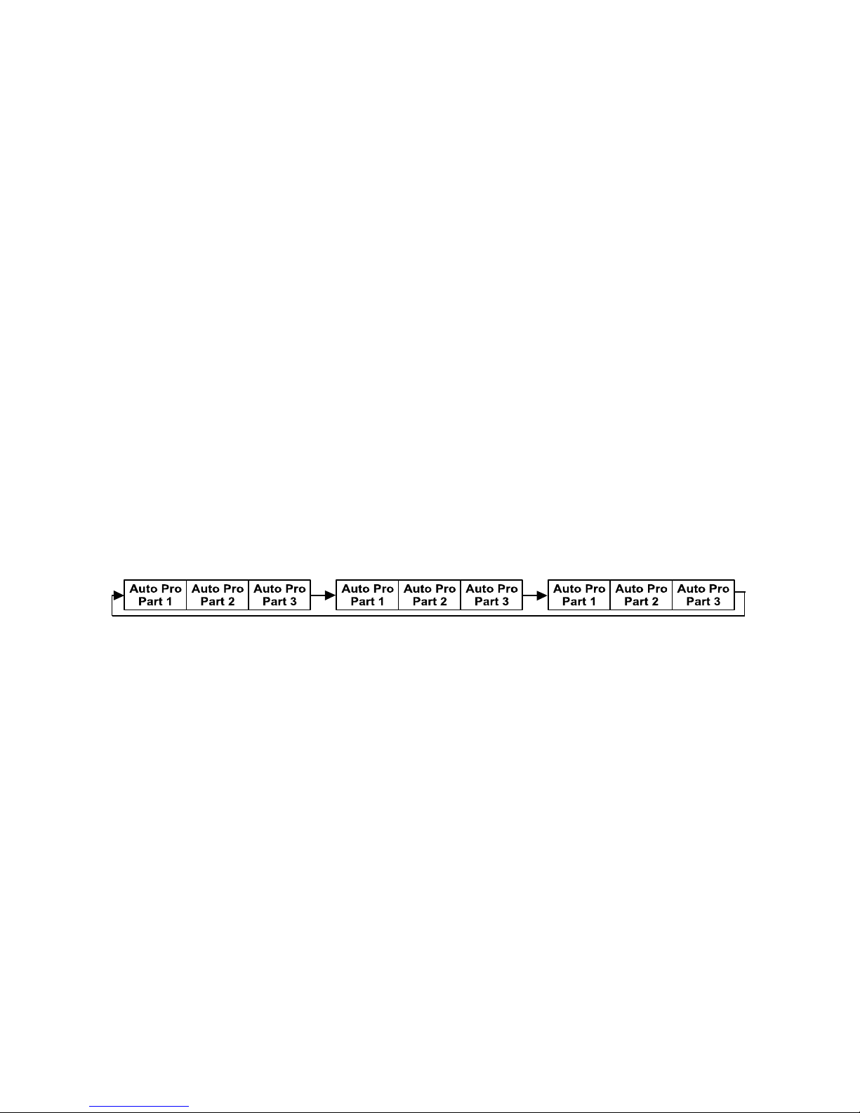
Excursion:
A Master unit can send up to 3 different data groups to the Slave units, i.e. a Master unit
can start 3 different Slave units, which run 3 different programs. The Master unit sends
the 3 program parts in a continuous loop.
The Slave unit receives data from the Master unit according to the group which the Slave
unit was assigned to. If e.g. a Slave unit is set to “Slave 1” in the menu “Set to Slave”, the
Master unit sends “Auto Program Part 1” to the Slave unit. If set to “Slave 2”, the Slave
unit receives “Auto Program Part 2”.
To start a Auto Program please proceed as follows:
1. Slave-Setting
• Select “Function Mode” by turning the encoder.
• Press the Enter button to confirm.
• Select “Set to slave” by turning the encoder.
• Press the Enter button to confirm.
• Turn the encoder to select “Slave 1”, “Slave 2” or “Slave 3”.
• Press the Enter button to confirm.
• Press the Mode/Esc button in order to return to the main menu.
2. Automatic Program Run
• Select “Function Mode” by turning the encoder.
• Press the Enter button to confirm.
• Select “Auto Program” by turning the encoder.
• Press the Enter button to confirm.
• Turn the encoder to select “Master” or “Alone”. The selection "Alone" means Stand
Alone-mode and "Master" that the device is defined as master.
• Press the Enter button to confirm.

13
• Press the Mode/Esc button in order to return to the main menu.
3. Program selection for Auto Pro Part
• Select “Edit program” by turning the encoder.
• Press the Enter button to confirm.
• Select “Select programs” by turning the encoder.
• Press the Enter button to confirm.
• Turn the encoder to select “Auto Pro Part 1”, “Auto Pro Part 2” or “Auto Pro Part 3”, and
thus select which Slave program is to be sent. Selection “Part 1” means, that the Slave
unit runs the same program as the master units.
• Press the Enter button to confirm.
• Press the Mode/Esc button in order to return to the main menu.
4. Program selection for Edit Program
• Select “Edit program” by turning the encoder.
• Press the Enter button to confirm.
• Select “Edit program” by turning the encoder.
• Press the Enter button to confirm.
• Turn the encoder to select the desired program. With this function you can edit specific
scenes into a specific program.
• Press the Enter button to confirm.
• Press the Mode/Esc button in order to return to the main menu.
5. Automatic Scene Recording
• Select “Edit program” by turning the encoder.
• Press the Enter button to confirm.
• Select “Edit scenes” by turning the encoder.
• Turn the encoder to select the desired scene numbers. You can program a maximum
number of 250 • Turn the encoder to select the desired scene numbers. You can program
a maximum number of 250 scenes.
• Press the Enter button to confirm.
• Press the Mode/Esc button in order to return to the main menu.
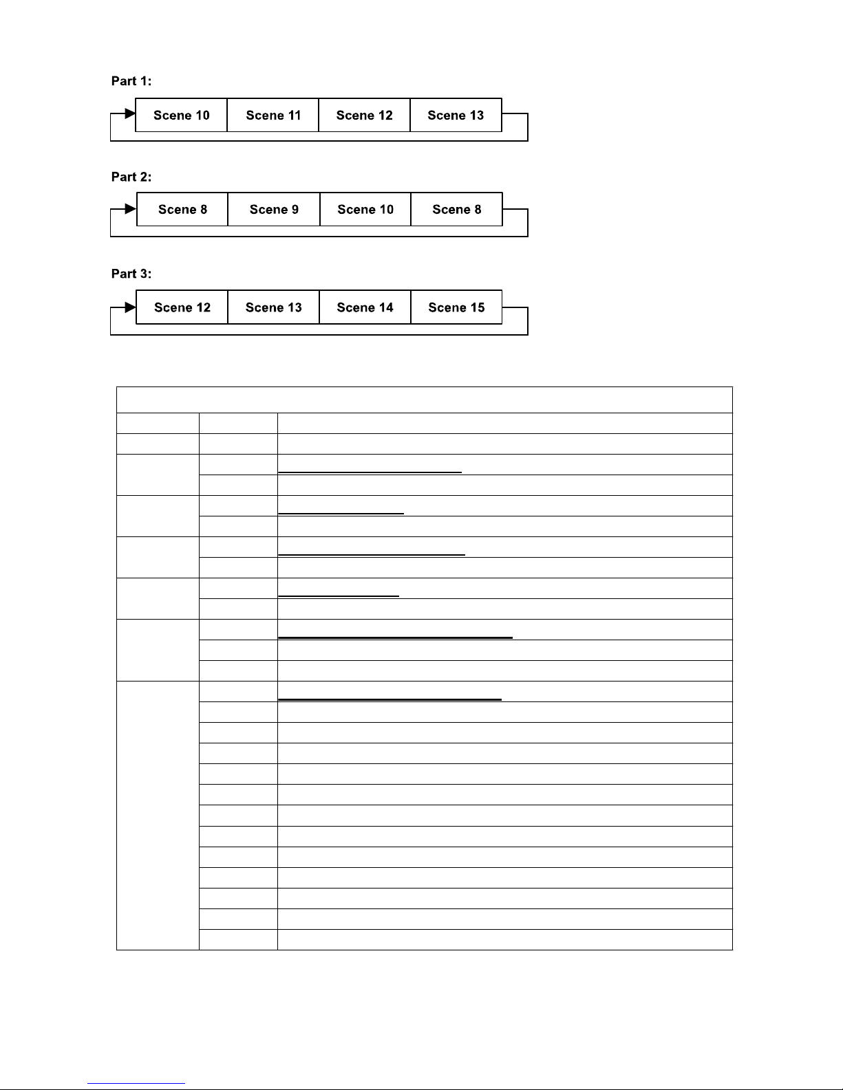
Example:
Program 2 includes scenes: 10, 11, 12, 13
Program 4 includes scenes: 8, 9, 10
Program 6 includes scenes: 12, 13, 14, 15
Auto Pro Part 1 is Program 2;
Auto Pro Part 2 is Program 3;
Auto Pro Part 3 is Program 6
The 3 Slave groups run the Auto Program in certain time segments, as shown in the
following picture:
14
12. INSTRUCTIONS ON USE:
DMX channel´s functions and their values (6 DMX channels):
Channel
Value
Function
St
PAN Movement 8bit :
1
0-255
Pan Movement
Pan Fine 16bit
2
0-255
Fine control of Pan movement
TILT Movement 8bit :
3
0-255
Tilt Movement
Tilt Fine 16bit
4
0-255
Fine control of Tilt movement
Speed Pan/Tilt movement:
5
0-225
Max to min speed
5
226-255
No function
Reset, internal programs:
0-79
No function
80-84
All motor reset
85-87
Scan motor reset
88-99
No function
100-119
Internal program 1 (secne1~8 of EEPROM)
6
120-139
Internal program 2 (secne9~16 of EEPROM)
6
140-159
Internal program 3 (secne17~24 of EEPROM)
6
160-179
Internal program 4 (secne25~32 of EEPROM)
6
180-199
Internal program 5 (secne33~40 of EEPROM)
6
200-219
Internal program 6 (secne41~48 of EEPROM)
6
220-239
Internal program 7 (secne49~56 of EEPROM)
6
240-255
Music Control (secne of Program 1)
ERROR MESSAGE

15
When you turn on the fixture, it will make a reset at first. The display may show “Err
channel is XX” while there are problems with one or more channels. “XX” stands for
channel 1, 3, 5,etc who has the testing sensor for positioning.For example, when the
display shows “Err channel is Pan”, it means there is some error in channel 1. If there are
some errors on channel 1, channel 3, channel 5 at the same time, you may see the error
message“Err channel is Pan”, “Err channel is Tilt”, “Err channel is Speed Pan/Tilt
movement” flash repeated for 2 times, and then the fixture will generate a second reset.
If the fixture remain error message after performing reset more than 2 times, only the
channels which have errors can not work properly, others can work as usual. Please
contact with dealer or manufacturer for service, self repair is not allowed.
PAN- movement Er
(PAN-yoke movement error) This message will appear after the reset of the fixture if the
yoke’s magnetic-indexing circuit malfunction (sensor failed or magnet missing) or the
stepping-motor is defective (or its driving IC on the main PCB). The PAN- movement is not
located in the default position after the reset.
TILT- movement Er
(TILT-head movement error) This message will appear after the reset of the fixture if the
head’s magnetic-indexing circuit malfunctions (sensor failed or magnet missing) or the
stepping-motor is defective (or its driving IC on the main PCB). The TILT- movement is not
located in the default position after the reset.
Software fractional introduce
13: Install and Uninstall
13.1 Features
<LED Manager 2010> is a professional player developed for LED display system, with
the powerful feature of easy-to-learn and easy-to-use.
<LED Manager 2010> almost supports all of the mainstream media of computer files,
such as:
Videos: AVI/SWF/RM/MPEG/MPG...
Pictures: JPG/GIF/BMP/...
Files: txt/doc/xls/rtf/…
<LED Manager 2010>can be smoothly implemented to play controls on a general
computer; can be carried out several display window editor on one computer, and better
support for external video and audio input.
16
13.2 Operating environment
Operating System
Windows2000/ XP Chinese and English
Hardware
CPU: Celeron 2.4G or higher
Memory: 1G or higher
Display card: 32M or higher
Related Software
Video Decoder--compulsory
Microsoft Media player--compulsory
OFFICE2000—in case of *.doc files
RealPlayer—in case of RM or RMVB files
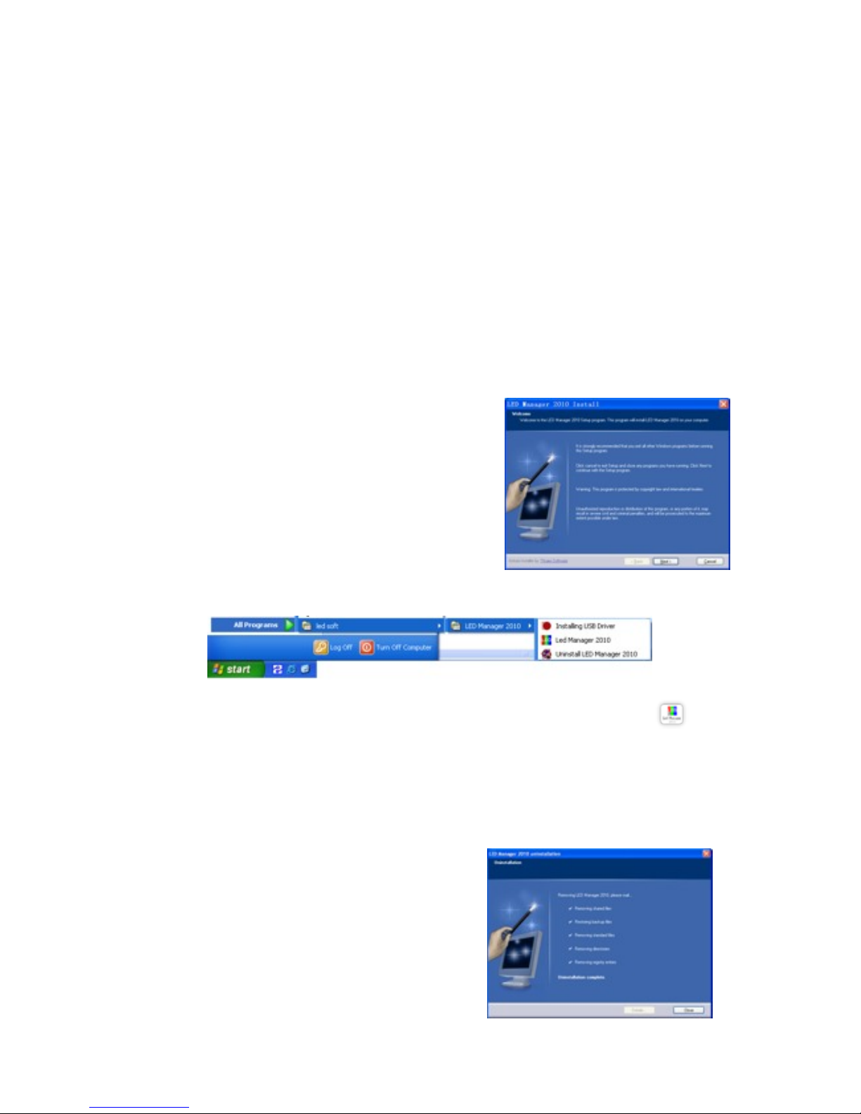
13.3 Install
It is simple to install the <LED Manager 2010> as
below: Double-click LED Manager 2010 file and then
dialog box popup, see Fig.2-1, select <Next step> to
start installing.
When the installation of the <LED Manager 2010> is
made, the <LED software> will appear in the <Start/
<Program>. Click to start operation after entering
<LED Manager 2010> in the program as Fig. 2-2
shows.
Fig.2-2
And there is a shortcuts of < LED Manager 2010> in the desktop as icon shows,
double-click it can start the program.
13.4 Uninstall
<LED Manager 2010> offers the feature of
automatic un-installation which is convenient for
you to delete all related files, programs and
shortcuts. User can select <Uninstall LED
Manager 2010> in the <LED software> as Fig.
2-2 shows, and can select <Add/Delete
Programs> in the <Control Panel>, to uninstall
software. Click Uninstall, the pop-up dialog box
will ask for confirmation to uninstall the software,
click the confirmation button, the software will
uninstall automatically. The process is completed
Fig. 2-1
Fig.2-3
17
as Fig.2-3 shows.
14. Use details
14.1 Program composition
Program (program files) includes one or more episode. And there are two kinds of
episode: normal episode and instant messaging programs. The former is the main
component of program, which can have more than one and be played in order; the latter
is only one which will be cycle played during the whole process, it is used to play a fixed
content.
Episode is composed of one or more multimedia window, which is used to display such
contents as the text, images, flash, multimedia clips. Multimedia windows can load 12
types of multimedia materials to play: <Material File>, < Text display >, < Text display >,
< Time display >, < Audio control >, < External video >, < Custom Form >, < External
program window >, < Database Display >, < Web display >, < Temperature/humidity
window >, < Instant messaging > and < Screen capture >.
Material files: including pictures, video, flash, word, Excel and other media files.
Text display: including single-line text, multi-line text and Flash effects characters.
Time display: including the clock display, timer time display.
Audio control: including audio visual images and audio spectrum image.
External video: for other external video devices.
Custom Form: tabular data for editing play.
External program window: for embedding the external program into the display
window, mainly for playing small programs user developed for themselves.
Database Display: including ACCESS database and ODBC databases.
Web display: used to display web pages.
Temperature/humidity window: including environmental temperature and humidity.
Instant messaging: for quick input a short text, such as notification letter.
Screen capture: used to record the current screen image inside the window.
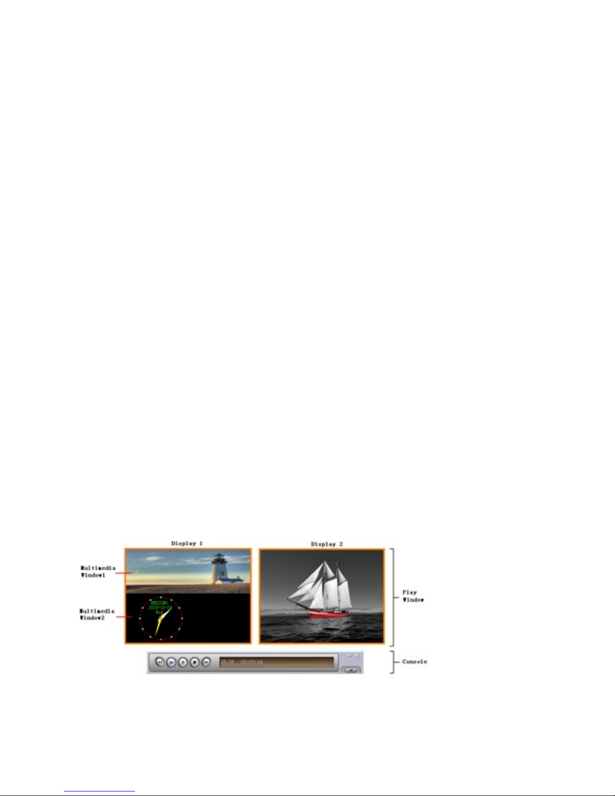
14.2 Introduction of interface window
The main interface of <LED Manager 2010> shows as Fig.3-1, it includes two windows:
Play Window and Console.
Fig.3-1

18
14.2.1 Play Window
Play window (The contents are displayed on the LED screen) is used to play the text,
images, animation, multimedia clips and other content the user want to. Here's the
content coincides with what the LED screen shows. This software supports play windows,
up to 99 maximally, that means one computer can control the 99 pieces of display
screen. Each play window can have several multimedia windows. And each multimedia
window can load twelve types of multimedia files (that is described in chapter
3.1). Independently, each player window can open program files and standalone play,
independent editing without affecting the other play window.
14.2.2 Console
Console is used to control the position, size and program content of play window. The
console can be expanded into edit mode, the expanded control buttons as shown by the
red mark in Fig 3-2.
Fig 3-2
In the edit mode, you can clearly see the console to expand in three parts, as shown in
Fig.3-3: Function Menu, Control Strip and Edit Area.
Fig 3-3
Function Menu: orderly including seven sub-menu <Files>, <Edit>, <New>,
<Material>, <Settings>, <Tools>, <Help>.
Control Strip: orderly including five functions of <Back>, <Play>, <Pause>, <Stop>,
<Forward>
Edit Area: the toolbar at the top in sequence includes <new episode or media window>,
<import>, <move up>, <move down>, <delete>, <play>, <stop play>, <zoom in>,
<zoom out>; left are the options for the program, show programs and sub- window
information; the right are options to edit, includes the special play effects, content ,time
and so on.
 Loading...