

Page 1
DR-PRO RACK
USB
SD CAR D
SMPTE
MIDI
DMX OUT
DMX IN
1 2 3 4 5 6 7 8
MEMORY
PAUSE STOP
BLACK OUTPLAY
D -PRO RACKR
DMX RECO RDER
User’s Manual
Page 2
Safety Precaution
Note
Please read this entire manual to fully understand and safely use this product.
Specifications are subject to change without prior notice.
Unpacking
Unpack and carefully examine the product.
Report any damage and save all packing materials if any parts damaged during transport.
Do not attempt to use this apparatus if it is damaged.
This shipment packing includes:
DR-PRO Rack, 1pcs
User's Instruction, 1pcs
USB Cable, 1pcs
Transformer, 1pcs
Safety Note
Please read all instruction prior to assembling, mounting, and operating your DMX Recorder Pro Rack. To
protect against fire, electric shock and injury to persons, please follow the safety precautions listed below
and observe all warnings in this manual and warnings printed on the console. The following rules give
important information regarding safety during operation and maintenance for long term use. If you have any
questions regarding operation of this console, please contact our local suppliers or distributors.
• Use only a source of AC power that complies with local building and electrical codes and has both
overload and ground-fault protection.
• To reduce the risk of fire or electrical shock, do not expose this unit to rain or high levels of moisture.
Do not use this unit near water.
• Refer any service operation not described in this manual to a qualified technician.
• Do not dismantle or modify this unit as there are no user serviceable parts inside. Refer all service
related issues to a qualified technician.
• Handle this unit carefully. Any strong shock or vibration may result in malfunction.
• Do not operate this unit when front face panel is removed.
• Any damaged or crimped AC cable should be replaced immediately. Protect the power supply cable
from being walked on or pinched.
• Do not allow children to play with this unit.
• Keep these instructions for future use.
• Heed all warnings.
• Follow all instructions.
• Clean only with dry cloth.
• Do not install near any heat sources such as heaters, stoves, amplifiers or any other heat generating
apparatus.
• Only use attachments and accessories specified by Philips Professional.
• Unplug this unit during lighting storms or when unused for long periods of time.
-1-
24-004-3398-00
Rev 1.0
Page 3
General Instructions
Descriptions
Thanks for you purchasing DMX Recorder Pro Rack. The present content pretends to make a description of
the technical features, Specifications and operation, etc.
Features
128x160 Characters color LCD display
Up to 8 memories with individual Master setting allows users to assign Scenes, Chases or Shows.
Consisting of 5 operation modes: Manual control, Real-time trigger, SMPTE/MIDI time code trigger, DMX trigger and
-
DMX monitor
Over 5 hours recording time for Show and up to 4 different recording modes available, including Manual, Auto, Semi-
-
Auto and Smart
Allows to record SCENE, create CHASE and set Fade/Hold time for every step of the CHASE.
Password lock function
Standard DMX-512(1990) and DMX-1000K(1M) protocol compatible
3pin XLR DMX male/female connector, SD card port, USB port, 3pin SMPTE port and 5pin MIDI input
External Dry Contact available
-
- Programme updatable
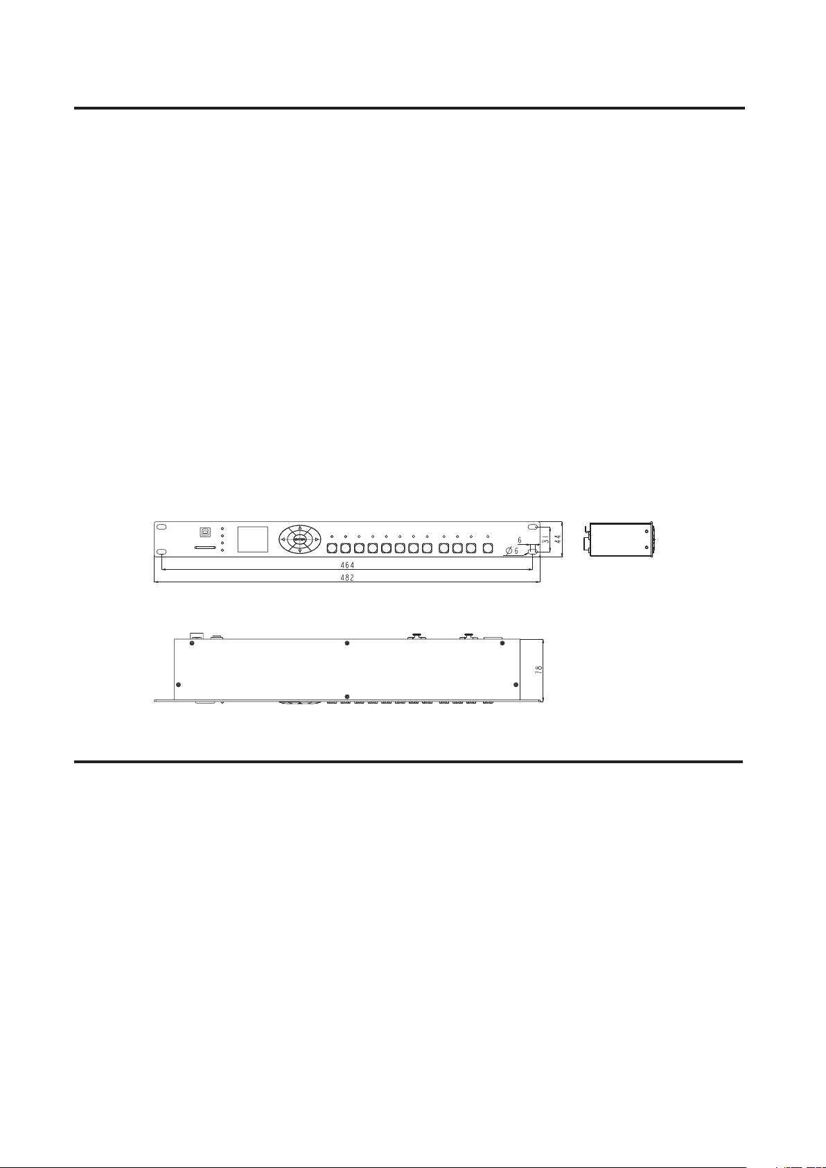
Physical Dimensions
Technical Specification
POWER INPUT
CONNECTOR
LCD DISPLAY
COMPLIANT PROTOCOLS
HOUSING
LISTING
INGRESS PROTECTING RATING
OPERATING TEMPERATURE
STORAGE TEMPERATURE
DIMENSIONS
WEIGHT
Unit: mm
DC9-12V, 500mA Min
3-pin XLR connectors for DMX in/out,
USB port for communicating with PC
3pin SMPTE input, 5pin MIDI input
128x160 Characters
Standard DMX-512(1990) and
DMX-1000K(1M) protocol compatible
Metal sheet with powder finishing
CE certified
IP20
-10 degC to +50 degC
-20 degC to +70 degC
482(L) x 78(W) x 44(H)mm
1.2kg
,
-2-
Page 4

Overview
Front View
5
1
6
7
9
10
1
1
USB
SD CARD
SMPTE
MIDI
DMX OUT
DMX IN
2
3
4
8
1 2 3 4 5 6 7 8
MEMORY
1. USB Port
Connects to PC for communications and program updating.
2. SD Card Port
Use to insert SD card for data transmission.
3. DMX OUT Indicator
This LED blinks when sending DMX signal.
4. DMX IN Indicator
This LED blinks when DMX signal inputs.
5. MIDI Indicator
This LED will blink when an available MIDI time received in SMPTE/MIDI Trigger
mode.
PAUSE STOP
BLACK OUTPLAY
D -PRO RACKR
DMX RECO RDER
6. SMPTE Indicator
This LED will blink when an available SMPTE time received in SMPTE/MIDI
Trigger mode.
7. 128x160 color LCD Display
Shows the current activities.
8. LEFT/RIGHT/UP/DOWN/OK Button
Used to select function.
9. Memory 1~8 Button
Used to select the memory you want to play in Manual mode.
10. PLAY/PAUSE/STOP Button
Used to select the running status of memory in Manual mode.
11. BLACK OUT Button
Controls DMX output in Manual mode.
-3-
Page 5

Overview
Rear View
3
4
5
8
9
MEMO RY
5
PAUSE STOP
6
7
6
BLAC K OUT
1=Grou nd
2=Data 3=Data +
DMX IN
1
MIDI IN
3
5
1. 2. 3=NC ; 4=V+; 5 =Sign al
SMPTE INDMX OUT
1
4
2
1 2 3 4
1=Grou nd
2=Data 3=Data +
PLAY
2
1. DMX IN
Inputs the external DMX signal
2. DMX OUT
Outputs the DMX signal
3. MIDI IN Port
Inputs MIDI time
4. SMPTE IN Port
Inputs SMPTE time
5. MEMORY1~8 contact point
Connects the external contact point switch may control the Memory1~8
Power Input:
9-12 VDC, 50 0mA Min
8
Seri al Numb er:
Made in P.R. C.
POWER
RoHS
7
6. PLAY/PAUSE/STOP contact point
Connects the external contact point switch may control the function of PLAY/PAUSE/STOP
7. Blackout contact point
Connects the external contact point switch may control the Blackout function
8. ON/OFF
Power On/Off the unit
9. DC In
Connects the power source of DC 9~12V
-4-
Page 6

Operation Guide
1)Select Work Mode
There are 5 work modes available for DMX Recorder Pro Rack:
1)Manual control
2)Real-time trigger
3)Time code trigger
4)External DMX trigger
5)DMX monitor
The user may press the OK Button and keep hold it for 2 seconds, the Work Mode option menus appears, now use
Up/Down button to select the work mode, and press OK to confirm.
2)Set User Parameters
2.1)When the Work Mode option menu appears,
password "1234"(the default password was set as "1234"), the function option menu appears.
2.2)Record/modification of DMX data.
2.2.1)Record DMX
The user may use this function to record SCENE and SHOW, use the recorded SCENE to edit CHASE.
2.2.2)Record a SCENE
To choose and access Record SCENE function, use function button to modify SCENENAME. Select Confirmation &
Record, press OK to record the current inputed DMX data. The LED indicator will flash 3 times. After finish, to select
"Finish & Return" to return.
2.2.3)Record a SHOW
To choose and access Record SHOW function, use function button to modify SHOWNAME. There are 4 record methods
for user choice: Manual, Auto,Semi-Auto and Smart.
2.2.3.1)Manual
Press Start button to start record, and then press Stop button to finish.
use Up/Down button to select "SET & MODIFY", press OK and input
2.2.3.2)Auto
Once the recorder received at least a frame which all DMX data are "zero", the recorder is assumed to be in the
state of ready to record, when received any “nonzero" DMX data, start to record, when received all "zero" DMX
data again, record completed.
2.2.3.3)Semi Auto
The theory is the same as the Auto mode. The difference is that in Semi Auto mode, need to press "Stop" to finish
record. Or, when received all "zero" DMX data, record completed.
2.2.3.4)Smart
This mode is applied to those DMX data which were played in a circle with changes, and the DMX data frame
must be the totally same in the circle playback.
2.2.3.5)Select "Confirm & Record" to access Record control state.
Select "Start Record" to record. The recorder will handle the record in terms of the selected record method. If want
to finish record in advance, you can select" Stop & Return".
2.2.4)Add a Chase(The user may use this recorder to edit Chase only if the Scene had been recorded in it.)
2.2.4.1)Select Add Chase to edit Chase.
2.2.4.2)Use function button to modify CHASENAME.
2.2.4.3)In "STEP: xxx/yyy", the specified step may be modified.
2.2.4.4)Select the Scene of Step in "SceneName xxx/yyy".
2.2.4.5)Modify the time parameters of the current step in "HoldTime/FadeYime".
2.2.4.6)After the current parameters setting completed, select "Confirm & Save" to record the current step parameter.
2.2.4.7)Select " Finish & Return" to return.
xxx: the current step
yyy: the recorded total steps of this Chase, up to 200 steps can be recorded.
xxx: the current Scene
yyy: the total Scenes available for option
-5-
Page 7

2.2.5)Modify the recorded Chase
2.2.5.1)To select "Edit Chase" and access it, use Up/Down to select the Chase you want to modify, press OK to
confirm.
2.2.5.2)Now the user may use function button to modify ChaseName, the Scene of the specified Step, HoldTime
and FadeTime.
2.2.5.3)Also the user may do "Insert Step" and " Delete Step".
2.2.5.4)Select "Confirm & Return" to return.
2.2.6)Delete Scene/Delete Show/Delete Chase
2.2.6.1)Use this function will delete the specified Scene/Show/Chase.
2.2.6.2)Select "Finish & Return" to return.
2.3)Edit the trigger event
2.3.1)Select "Trigger Event"
2.3.2)There are 3 trigger methods available: Time Event, SMPTE/MTC Event and external DMX trigger.
2.3.3)Time Event
2.3.3.1)The Time Event includes Weekly and Dately mode. In this trigger method, the event will be triggered
according to the calendar clock.
2.3.3.2)Weekly Mode
2.3.3.2.1)Add a Weekly event
2.3.3.2.2)Select Weekly
2.3.3.2.3)Use function button to modify EventName, trigger time, trigger memory, memory playback state, output
state, etc.
2.3.3.2.4)Select "Confirm& Save", record the current event.
2.3.3.2.5)Select "Finish & Return" to return.
2.3.3.3)Dately Mode
2.3.3.3.1)Add a Dately event
2.3.3.3.2)Select Dately
2.3.3.3.3)Use function button to modify EventName, trigger time/date, trigger memory, memory playback state,
output state, etc.
2.3.3.3.4)Select "Confirm& Save", record the current event.
2.3.3.3.5)Select "Finish & Return" to return.
Note: Due to the precedence of Dately event is higher than Weekly event, in order to trigger the Weekly event while the
Dately event finished it is required to add a "no memory" Trigger after the Dately event .
2.3.3.4)Edit Weekly Event
2.3.3.5)Edit Dately Event
2.3.3.4.1)Select "Edit Weekly"
2.3.3.4.2)Use function button may modify EventName, trigger time, trigger memory, memory playback state,
output state, etc.
2.3.3.4.3)Use function "Select Event" and press Left/Right button to select event.
2.3.3.4.4)Select "Finish & Return" to return.
2.3.3.5.1)Select "Edit Dately"
2.3.3.5.2)Use function button may modify EventName, trigger time, trigger memory, memory playback state,
output state, etc.
2.3.3.5.3)Use function "Select Event" and press Left/Right button to select event.
2.3.3.5.4)Select "Finish & Return" to return.
EventName xxx/yyy
xxx, the current event serial number.
yyy, the total event quantity.
EventName xxx/yyy
xxx, the current event serial number.
yyy, the total event quantity.
-6-
Page 8

2.3.3.6)Delete Weekly/Delete Dately
Use this function may delete the specified event.
2.3.4)Select "Finish & Return" back to the previous level.
2.3.5)SMPTE/MTC Event
This event is triggered by the external assigned time.
2.3.5.1)The user may add Trigger Event, edit event and delete event in this mode.
2.3.5.2)Select Add SMPTE/EMC
2.3.5.3)The user may set EventName, Frame Rate, trigger time, trigger memory, playback state, output state, etc.
2.3.5.4)Select "Confirm & Save" to record the current event
2.3.5.5)Select "Finish & Return" to return.
2.3.6)Select "Edit SMPTE/MTC"
2.4)Set DMX trigger parameters
2.3.6.1)The user may set EventName, Frame Rate, trigger time, trigger memory, playback state, output state, etc.
2.3.6.2)Use function "Select Event" and press Left/Right button to select event.
2.3.6.3)Select "Finish & Return" to return.
2.3.7)Select "Delete SMPTE/MTC" to delete the specified event.
2.4.1)Set DMX Start Address
This recorder receives three channels DMX data, the operation instructions detailed as below.
DMX Channel
DMX Values
0 ~3, Trigger Memory 1;
4~7, Trigger Memory 2;
Starting Channel
9~11, Trigger Memory 3;
........
28~31, Trigger Memory 8;
Above 31, the Memory unchanged.
0~79 , Pause;
Starting Channel
+1
Starting Channel
2.4.2)No DMX IN
This function is used to set Manual/Timer to trigger event while there is no DMX input in the work mode of DMX Trigger
or DMX Monitor.
2.4.3)No SMPTE/MIDI IN
This function is used to set Manual/Timer to trigger event while there is no external time input in the work mode of
SMPTE/MIDI Trigger or DMX Monitor.
2.5)Assign Memory
2.5.1) Select Assign Memory
2.5.2) Select Memory1-8, and play Memo/Stop Memo/Blackout Memo
2.5.3) Select Assign Type( Scene, Chase and Show are available for option)
+2
xxx/yyy
xxx, the current Type serial number
yyy, the total available Type quantity
80~159 , Play;
Above 159 , Stop.
0~127 , Normal Output,
Above 127, Blackout.
2.5.4) "Assign" is used to assign the specified contents.
2.5.5) "Master" is used to set the Master value for the current memory.
-7-
Page 9

2.6)Modify Clock
2.7)Set password
2.8)Data Backup
3)Communications
2.5.6) Select "Scene" may set FadeTime for it.When select Chase or Show, may set the Speed Scale of playback.
2.5.7) Select "Finish & Return" to return.
This function is used to modify the inner calendar clock.
This function is used to modify user password.
This function is used to copy the parameters of this recorder.
2.8.1)Data Backup
It has to insert SD card prior to using this function.
2.8.2)The detail function will be instructed as below.
Scene SD Card: Copy all the data of Scene from recorder to SD card.
Chase SD Card: Copy all the data of Chase from recorder to SD card.
Show SD Card: Copy all the data of Show from recorder to SD card.
Memory SD Card : Copy all the assigned data of memory from recorder to SD card.
Event SD Card: Copy all the Event information from recorder to SD card.
Picture SD Card: Copy all the pictures from recorder to SD card.
All SD Card: Copy all the above data from recorder to SD card.
SD Card Scene: Copy all the data of Scene from SD card to recorder.
SD Card Chase: Copy all the data of Chase from SD card to recorder.
SD Card Show: Copy all the data of Show from SD card to recorder.
SD Card Memory: Copy all the data of Memory from SD card to recorder.(This operation will overwrite the old
Memory in recorder.)
SD Card Event: Copy all the Event information from SD card to recorder.(This operation will overwrite the old
Event in recorder.)
SD Card Picture: Copy all the pictures from SD card to recorder.
SD Card All: Copy all the above data from SD card to recorder.
2.8.3)Select "Exit" to return.
DMX Recorder Pro Rack pro also can communicate with PC via USB cable. In your PC you will find a dummy U disk
while the recorder connected to PC so that you can copy the data directly.
Note: The recorder can only read/process the file which name length not exceed 8 characters and the extension length
not exceed 3 characters.
4)Program Updating
Remote program updating function is available for DMX Recorder Pro Rack.
Disconnect the main power, and keep pressing the Right button and OK button, then power on the device again. Connect
the device with PC via a USB cable, and the unit will be recognized as a removable storage, Copy the latest updating file
to the to the removable storage will finish the update process.
-8-
 Loading...