

Page 1
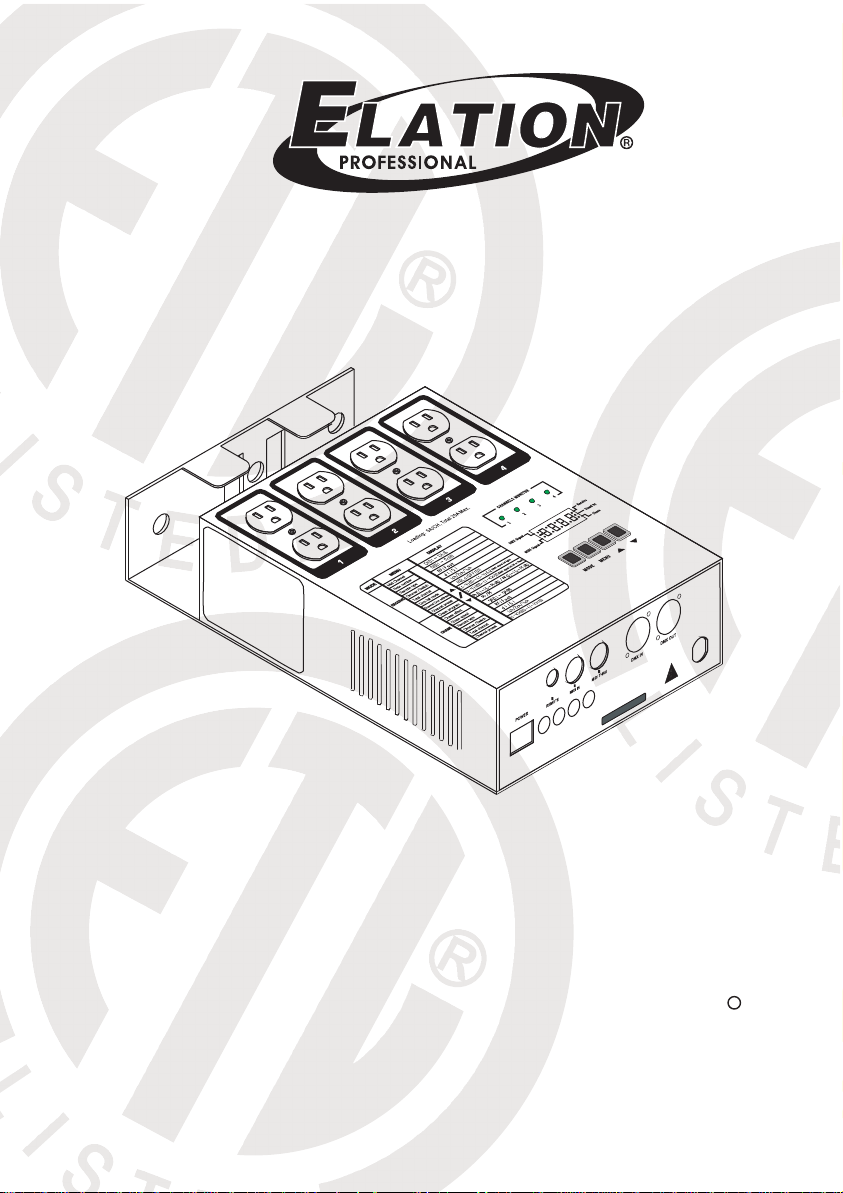
CYBER PAK
User Instructions
Elation Professional
4295 Charter Street
Los Angeles CA. 90058
www.elationlighting.com
R
Page 2

Page 3

Contents
Features 1
General Instructions 2
1. Overview 3
1.1 Front Panel 3
1.2 Rear Panel 4
2. Operation Guide 5
2.1 Receive Mode 5
2.1.1 Receive Enable 5
2.1.2 MIDI Channel 5
2.1.3 Note Number 6
2.1.4 DMX Fail mode 7
2.1.5 Channel DMX Address 7
2.1.6 1CH./ 2CH./ 4CH. Dimmer Pack 8
Improvement and changes to
this manual, specifications
and design, may be made at
any time without prior notice.
R
C US
9901286
2.2 Chase Mode 9
2.2.1 Chase Enable 9
2.2.2 Chase Program 9
2.2.3 Chase Effect 10
2.2.4 Chase Speed 11
2.2.5 4 Channel Chaser 11
2.3 Dimmer Pack/ Switch Pack 12
2.4 Channel Dimmer Mode 13
2.5 Remote Type 13
Technical Specifications 15
Page 4

Features
Thank you for your purchase. This product features include:
4 channel chaser with 16 built-in chase programs
4 channel dimmer pack with 4 individual DMX channel
Serves as a MIDI pack to receive MIDI Note Number(001-128)
Dimmer pack and Switch pack can be selectable
1,2, 4 channel dimmer pack depending on your adjustments
Fade-in or Fade-out of the chase programs
DMX fail allows to set HOLD/OFF/ON of output
Remote type includes FOOT and RF control
Power failure memory.
Every effort has been made to design dependability, reliability and comfort
into each unit. New products are being designed constantly to meet the
needs of both entertainment and the lighting industry. We welcome your
comments about our product and services.
It is both a privilege and a pleasure serving you.
1
Page 5

General Instructions
Please read through this operating instructions before installing or using
your new product. After you have finished reading the instructions, put
them away in a safe place for future reference.
Safe and Efficient Use
This product must be earthed.
Do not make any inflammable liquids, water or metal objects
enter the unit.
Take care not to damage the power cord.
No user serviceable parts inside, always consult authorized
personnel for repairs.
In the event of a malfunction(burning smell, etc.), immediately
stop operation, disconnect the power supply plug, and consult
authorized service personnel.
To prevent fire or shock hazard, do not expose this product to
rain or moisture.
Product Care
This product is intended for indoor use only.
Provide occasional ventilation during use.
Unplug the power plug from the sockets when not using the
unit for extended period.
Do not use the unit in places subject to excessive humidity,
vibration or bumps.
Place this unit in a stable location.
Do not dismantle or modify the unit.
2
Page 6
1. Overview
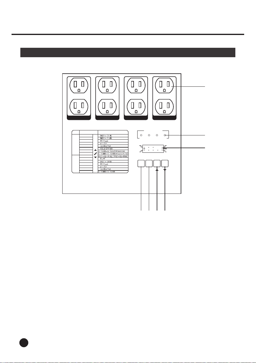
1.1 Front Panel
1
MENU
43
2
Receive
Stand by
Chase
3
MODE
RECEIVE
CHASE
1
Midi Channel
Note number
Remote type
Dimmer/Switch
Total channel
Dmx fail mode
Channel Dmx address
Channel preset
Chase program
Chase effect
Chase speed
Remote type
Dimmer/Switch
Total channel
Channel preset
MENU
2
Loading: 5A/CH, Total 20A Max.
DISPLAY
DMX Signal
MIDI Signal
CHANNELS MONITOR
1 4 32
8 8 8 8
MODE
4 5 6 7
1. Channel Output: 5A/CH., Total 20A max.
2. Channel LEDs: These LEDs will indicate their relevant
channel activity.
3. Segment Display: Shows the current programming and function state.
4. MODE button: This button changes the operating mode between
RECEIVE and CHASE.
5. MENU button: This button activates the different functions in
RECEIVE and CHASE modes.
6. UP button: This button raises the value or changes
the function mode.
7. DOWN button: This button lowers the value or changes
The function mode..
3
Page 7
1. Overview
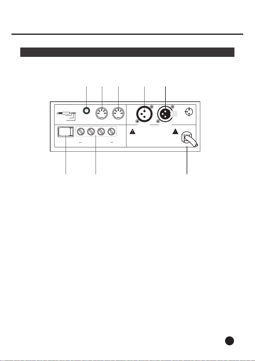
1.2 Rear Panel
3 4 5 6 7
1/4"stereo jack
GND
Stand By
Full on
POWER
REMOTE
MIDI IN
FUSES: F6A 250V 5x20mm
MIDI THRU
4321
1
3
2
DMX IN
AC 120V~ 50/60Hz, 15A max.
CAUTION
Risk of Electric Shock Disconnect Input Power
Before Opening
N'ouvrez pas..risque de choc electrique
Warning :This apparatus must be earthed
2
3
1
DMX OUT
PUSH
3
1 - Ground
2 - Data3 - Data+
2
1
1 2 8
1. Power switch: This switch controls units main power.
2. Channel Fuses: Each of the four channels is protected by a 6A fuse.
These fuses prevent you from overloading and damaging.
3. Remote connector: This connector is connected with a foot control or
detector(sold separately).
4. MIDI IN connector: This connector is used to receive MIDI signal from a MIDI
controller or MIDI sequencer.
5. MIDI THRU connector: This connector is used to transfer MIDI signal
to another MIDI device.
6. DMX IN connector: This connector is used to receive DMX signal
7. DMX OUT connector: This connector is used to transfer DMX signal to a DMX
power pack or dimmer.
8. Power Input Cord: Plug this cord into a matching power supply.
4
Page 8

2. Operation Guide
2.1 Receive Mode
This function allows you to turn on and control the intensity of the fixture with the
use of a DMX controller or MIDI sequencer. On, off and dimming functions can
be performed through this pack. This dimmer has 4 individual DMX address, DMX
fail mode allows you to assign output when DMX signal is interrupted. You may
also set your dimmer pack to function as 1,2,3 or 4 channel dimmer pack.
2.1.1 Receive Enable
Tap the Mode button until the Receive LED in
DMX
MIDI
MODE
CH:02
MENU
Receive
Stand by
Chase
the Segment Display lights, indicating Receive
mode is active.
When the unit is receiving a DMX signal, the
DMX LED will blink in the Segment Display
indicating a DMX signal is present.
When the unit is receiving MIDI signal, the
MIDI LED will blink in the Segment Display
indicating MIDI signal is present.
2.1.2 MIDI Channel
DMX
CH:02
MIDI
MENU
MODE
5
Receive
Stand by
Chase
1. Enter Receive mode, the Segment Display shows
"CH" followed by two numbers(01-16).
Page 9

2. Operation Guide
2.1.2 MIDI Channel
DMX
CH:03
MIDI
MENU
MODE
2.1.3 Note Number
DMX
MIDI
MENU
MODE
Receive
Stand by
Chase
Receive
Stand by
Chase
2. Tap the Up or Down button to select MIDI
channel from CH 01-16. Make sure your
MIDI channel matches that on the MIDI
sequencer.
1. Enter Receive mode. Tap the Menu button
until the Segment Display shows Note
Number.
DMX
MIDI
MENU
MODE
Receive
Stand by
Chase
2. Tap the Up or Down button to select desired
Note Number from 1-128.
6
Page 10

2. Operation Guide
2.1.4 DMX Fail mode
on
Receive
Stand by
Chase
Receive
Stand by
Chase
DMX
MIDI
MENU
MODE
DMX
MIDI
MENU
MODE
2.1.5 Channel DMX Address
1. Enter Receive mode, tap MENU until the Segment
Display shows HOLD/ OFF/ ON. DMX fail mode
allows you to set the output when DMX signal is
interrupted.
2. Tap UP/DOWN to change between HOLD, OFF
and ON.
[HOLD]: the last DMX setting is held in the outputs.
[OFF]: output is switch off.
[ON]: output is full on.
1. Enter Receive mode.
DMX
MIDI
MENU
MODE
Receive
Stand by
Chase
2. tap MENU until the Segment Display shows
DMX address, DMX LED lights up.
7
Page 11

2. Operation Guide
2.1.5 Channel DMX Address
DMX
MIDI
MENU
MODE
Receive
Stand by
Chase
3. Tap UP/DOWN to select DMX address from
001-512 for the channel.
4. Continue steps 2-3 until each of the four
channels has a DMX address.
2.1.6 1CH./ 2CH./ 4CH. Dimmer Pack
1. Enter Receive mode.
DMX
MIDI
MENU
MODE
DMX
MIDI
2
Receive
Stand by
Chase
Receive
Stand by
Chase
2. tap MENU until the Segment Display shows
channel output mode, this mode allows you
to set your dimmer pack to function as a 1,2.
4 channel DMX dimmer pack.
3. Tap the Up or Down button to change between
1ch/ 2ch/ 4ch.
MODE
MENU
[1ch]: all four channel output is controlled by
the first DMX channel.
[2ch]: channel one and two are controlled by
one DMX channel, channel three and
four are controlled by another DMX channel.
[4ch]: each of the four channels is controlled
by one DMX channel.
8
Page 12

2. Operation Guide
2.2 Chase Mode
If you set 4 channel output for this dimmer, this unit can be used as a 4 channel
chaser. This function allows you to select any of these 16 built-in programs or set
the pack to chase as desired to get a more dramatic light show. You may control
the speed at which the programs will chase.
2.2.1 Chase Enable
DMX
MIDI
MENU
MODE
2.2.2 Chase Program
DMX
MIDI
MENU
MODE
Receive
Stand by
Chase
Receive
Stand by
Chase
Tap MODE until the Chase LED in the Segment
Display lights, indicating Chase mode is active.
1. Enter Chase mode, the Segment Display shows
the chase program.
When the Segment Display shows "Pr" followed
by two numbers or "AU", any program selected
will chase instantly.
When the Segment Display shows "PF" followed
by two numbers or "AU", any program selected
will fade or glide between chase steps instead of
instantly changing. The rate of the change is adjusted
by the time between steps(chase speed).
[AU]: each of the 16 programs will be executed eight
times in sequence.
9
Page 13

2. Operation Guide
2.2.2 Chase Program
DMX
MIDI
MODE
3
MENU
2.2.3 Chase Effect
DMX
MIDI
MENU
MODE
DMX
MIDI
Receive
Stand by
Chase
Receive
Stand by
Chase
Receive
Stand by
Chase
2. Tap UP/DOWN to select from 1-16 programs.
1. In Chase Mode, tap MENU until Chase Effect
is activated.
2. Tap UP/DOWN to change between Pr and PF.
MENU
MODE
NOTE:
When this unit is set to function as a switch pack, the programs will chase
without fade-in or fade-out. Only when this unit serves as a dimmer pack,
you can set the programs to fade in or fade out.
10
Page 14

2. Operation Guide
2.2.4 Chase Speed
1. Enter Chase mode.
DMX
MIDI
DMX
MIDI
MODE
MODE
sp02
MENU
sp03
MENU
Receive
Stand by
Chase
Receive
Stand by
Chase
2.2.5 4 Channel Chaser
2. Tap the Menu button until the Segment Display
show "SP" followed by two numbers.
2. Tap UP/DOWN to select desired chasing speed.
The value 01 will give the slowest speed, and the
value 99 will give the fastest speed.
1. Enter Chase mode.
11
DMX
MIDI
MENU
MODE
Receive
Stand by
Chase
2. tap MENU until the Segment Display shows
channel output mode.
Page 15

2. Operation Guide
2.2.5 4 Channel Chaser
DMX
4
MIDI
MENU
MODE
Receive
Stand by
Chase
2.3 Dimmer pack/Switch pack
SI
Receive
Stand by
Chase
Receive
Stand by
Chase
DMX
MIDI
MENU
MODE
DMX
MIDI
MENU
MODE
2. Tap UP/DOWN to select 4ch mode. The
programs will chase only when this unit
serves as a 4 channel chaser.
1. In Receive or Chase mode, tap MENU until the
Segment Display shows "DI" or "SI".
2. Tap UP/DOWN to change between "DI" and
"SI".
If "DI" is selected, this unit serves as a dimmer
pack, you may adjust the intensity of each of
four channel, the programs will fade in or fade
out if Chase effect is active.
If "SI" is selected, this unit serves as a switch
pack, you can only turn on or off the output
and the programs will chase instantly.
12
Page 16

2. Operation Guide
2.4 Channel Dimmer Limit
DMX
MIDI
MENU
MODE
DMX
MIDI
MENU
MODE
2.5 Remote Type
Receive
Stand by
Chase
Receive
Stand by
Chase
1. In Receive or Chase mode, tap MENU until the
Segment Display shows channel dimmer limit,
DMX LED will be off or flash.
2. Tap UP/DOWN to adjust the value between 000-
100. Once the value is selected, the maximum
dimmer will be defined.
3. Continue steps 2-3 until you've set limit of maximum
dimmer of each of the four channel.
13
DMX
MIDI
MENU
MODE
Receive
Stand by
Chase
1. In Receive or Chase mode, tap MENU until the
Segment Display shows "FOOT" or "RF" .
Page 17

2. Operation Guide
2.5 Remote Type
DMX
rf
MIDI
Receive
Stand by
Chase
2. Tap UP/DOWN to change between FOOT and
RF modes.
If FOOT is selected, a foot control(sold separately)
is used to control this unit.
MODE
MENU
If RF is selected, a detector and a RF control(sold
separately) are required to be used.
Additional information: How to use RF control?
1. Turn off the unit's power.
2. While pressing MODE, apply power to this unit.
3. Tap any button on the RF control in five seconds, the RF control is chose to
serve this unit.
4. Repeat steps 1-2 to deselect the RF control.
14
Page 18

3. Technical Specifications
Power Input ..................................................... AC 120V ~ 50-60Hz, 20A max.
Channel Output ............................................................ 5A/CH., Total 20A max.
Channel Fuse ..................................................................... F6A 250V 5x20mm
DMX In/Out .................................................. 3-pin XLR male & female socket
MIDI In/Thru ........................................................................ 5-pin multi socket
Dimensions ............................................................................. 212x188x71mm
Weight .................................................................................................... 2.7 Kg
15
Page 19

Page 20

A Division of the American DJ Group of Companies
24-004-1253
Rev 1.0 March, 2004
Elation Professional
4295 Charter Street Los Angeles, CA 90058 USA
T
el: 323-582-3322 Fax: 323-582-3311
Web: www.elationlighting.com
E-mail: info@elationlighting.com
R
Page 21

Page 22

 Loading...