

Elation CUEPIX 16IP DTW User Manual
CUEPIX 16IP DTW™
user manual
©2019 ELATION PROFESSIONAL all rights reserved. Information, specifications, diagrams,
Date
Document
Version
Software
Version ≥
DMX
Channel Modes
Notes
06/18/19
1.0
1.0.1
7 (64 total channels)
Initial release.
10/03/19
1.2
1.X.X
9 (64 total channels)
Added additional DTW DMX modes.
images, and instructions herein are subject to change without notice. ELATION
PROFESSIONAL logo and identifying product names and numbers herein are trademarks of
ELATION PROFESSIONAL. Copyright protection claimed includes all forms and matters of
copyrightable materials and information now allowed by statutory or judicial law or
hereinafter granted. Product names used in this document may be trademarks or
registered trademarks of their respective companies and are hereby acknowledged. All
non-ELATION brands and product names are trademarks or registered trademarks of their
respective companies.
ELATION PROFESSIONAL and all affiliated companies hereby disclaim any and all liabilities
for property, equipment, building, and electrical damages, injuries to any persons, and direct
or indirect economic loss associated with the use or reliance of any information contained
within this document, and/or as a result of the improper, unsafe, insufficient and negligent
assembly, installation, rigging, and operation of this product.
Elation Professional USA | 6122 S. Eastern Ave. | Los Angeles, CA. 90040
323-582-3322 | 323-832-9142 fax | www.elationlighting.com | info@elationlighting.com
Elation Professional B.V. | Junostraat 2 | 6468 EW Kerkrade, The Netherlands
+31 45 546 85 66 | +31 45 546 85 96 fax | www.elationlighting.eu | info@elationlighting.eu
Elation Professional Mexico | AV Santa Ana 30 | Parque Industrial Lerma, Lerma, Mexico 52000
+52 (728) 282-7070
DOCUMENT VERSION
Due to additional product features and/or enhancements, an
updated version of this document may be available online.
Please scan the QR Code with your mobile device or visit
www.elationlighting.com for the latest revision/update of this
manual, before installation and/or programming.
2

CONTENTS
General Information
4
Warranty Returns (USA Only)
5
Safety Guidelines
6
Maintenance Guidelines
8
Fixture Overview
9
Installation Guidelines
10
System Menu
16
Pixel Control – Basic DMX Modes
19
Pixel Control – 4Ext DMX Modes
20
DMX Channels v1.0.1
21
DMX Channels v1.x.x
27
Error Codes
33
Specifications
34
Optional Accessories
36
3

GENERAL INFORMATION
INTRODUCTION
Please read and understand the instructions in this manual carefully and thoroughly before
attempting to operate this device. These instructions contain important safety and use
information.
UNPACKING
Every device has been thoroughly tested and has been shipped in perfect operating
condition. Carefully check the shipping carton for damage that may have occurred during
shipping. If the carton is damaged, carefully inspect the device for damage, and be sure all
accessories necessary to install and operate the device have arrived intact. In the event
damage has been found or parts are missing, please contact our customer support team for
further instructions. Please do not return this device to your dealer without first contacting
customer support. Please do not discard the shipping carton in the trash. Please recycle
whenever possible.
BOX CONTENTS
Safety Cable
Power Cable
CUSTOMER SUPPORT
Contact ELATION Service for any product related service and support needs.
Also visit forums.elationlighting.com with questions, comments or suggestions.
ELATION SERVICE USA - Monday - Friday 8:00am to 4:30pm PST
323-582-3322 | Fax 323-832-9142 | support@elationlighting.com
ELATION SERVICE EUROPE - Monday - Friday 08:30 to 17:00 CET
+31 45 546 85 63 | Fax +31 45 546 85 96 | support@elationlighting.eu
REPLACEMENT PARTS please visit parts.elationlighting.com
4

WARRANTY RETURNS (USA ONLY)
To ob t a in wa r ra n t y s er v ic e , a Re t u r n M at e r ia ls A ut h or i za t io n ( R MA ) n um b e r m u s t f ir s t b e
obtained from ELATION. It is the Customer’s responsibility to provide product proof of purchase
and serial number by acceptable evidence such as an invoice copy and any relevant
maintenance records at the time warranty service is sought. Failure to provide acceptable
evidence of product proof of purchase or any relevant maintenance records may be cause for
denial of warranty service.
Products returned for warranty service must be sent without any accessories (i.e., power, data,
and safety cables, brackets, clamps, rigging hardware, frost filters, gel frames, barn doors, lens,
hoses, nozzles, rack mounting hardware, etc.), must be boxed using the original and/or suitable
packaging materials (double-box and foam) that provides ample product protection for ground
and/or air freight transit, and must be shipped freight pre-paid and insured to ELATION in Los
Angeles, CA or an ELATION Authorized Service Center. The RMA number must be clearly
written on the outside of the return box, and a brief description of the problem and the RMA
number must be documented and included in the box.
Products returned for warranty service without an RMA number clearly marked on the outside
of the package will be refused and returned to the shipper at the Customer’s expense. Products
returned for warranty service, which are received damaged due to inadequate and/or improper
packaging and/or due to damage caused by shipping carrier, may incur additional repair
charges before warranty service begins and/or may void this warranty. If any product
accessories (included and/or optional) are shipped with the product, ELATION and/or the
ELATION Authorized Service Center shall have no liability what so ever for the loss and/or
damage to any such accessories, nor the safe return thereof. If the requested warranty repairs
or service (including parts replacement) are within the terms of this warranty, ELATION will pay
return ground transportation shipping charges to a single designated point within the United
States.
5
SAFETY GUIDELINES
This device is a sophisticated piece of electronic equipment. To guarantee a smooth operation,
it is important to follow all instructions and guidelines in this manual. The manufacturer of this
device is not responsible for injury and/or damages resulting from the misuse of this device
due to the disregard of the information printed in this manual. Only qualified and/or certified
personnel should use this device. Any modifications to the device will void the original
manufactures warranty and increase the risk of damage and/or personal injury.
PROTECTION CLASS 1 – FIXTURE MUST BE PROPERLY GROUNDED.
THERE ARE NO USER SERVICEABLE PARTS INSIDE THIS UNIT.
DO NOT ATTEMPT ANY REPAIRS YOURSELF; DOING SO WILL VOID YOUR
MANUFACTURERS WARRANTY. DAMAGES RESULTING FROM MODIFICATIONS
TO THIS FIXTURE AND/OR THE DISRETGARD OF SAFETY INSTRUCTIONS AND
GUIDELINES IN THIS MANUAL VOID THE MANUFACTURER’S WARRANTY AND
ARE NOT SUBJECT TO ANY WARRANTY CLAIMS AND/OR REPAIRS.
DO NOT PLUG DEVICE INTO A DIMMER PACK!
NEVER OPEN THIS FIXTURE WHILE IN USE!
UNPLUG POWER BEFORE SERVICING FIXTURE!
NEVER TOUCH FIXTURE DURING OPERATION, AS IT MAY BE HOT!
KEEP FLAMMABLE MATERIALS AWAY FROM THE FIXTURE!
ENSURE ALL CONNECTIONS AND ENDCAPS ARE PROPERLY SEALED WITH
DIALECTRIC GREASE (AVAILABLE AT MOST ELECTRICAL SUPPLIERS) TO
PREVENT WATER CORROSION AND/OR ELECTRICAL SHORT CIRCUIT.
NEVER LOOK DIRECTLY INTO THE LIGHT SOURCE!
RETINA INJURY RISK – MAY INDUCE BLINDNESS!
SENSITIVE PERSONS MAY SUFFER AN EPILEPTIC SHOCK!
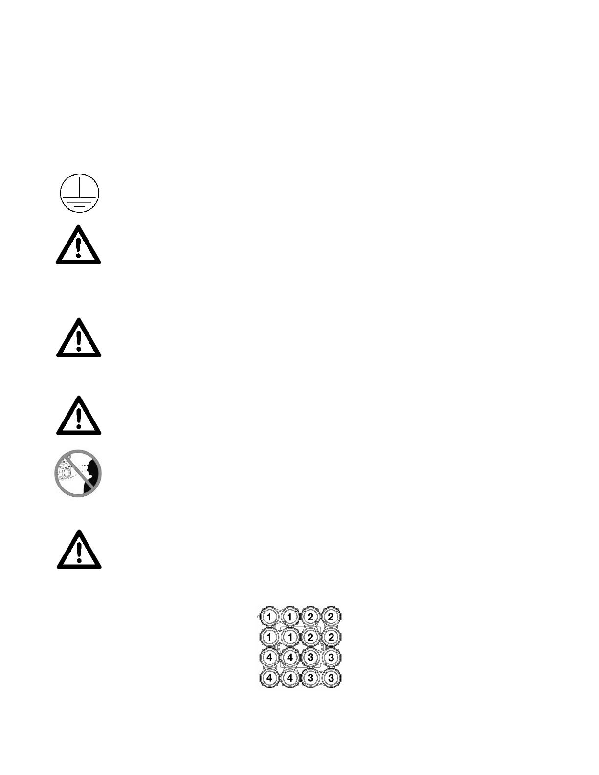
HIGH TEMPERATURE WARNING!!
IF THE INTERNAL TEMPERATURE REACHES 212° F (100°C) AND/OR A
SIGNAL WIRE/SENSOR IN ONE OF THE 4-CELL LED SEQMENTS BECOMES
DAMAGED OR DISCONNECTED, THE FIXTURE OLED DISPLAY WILL FLASH
“TEMP ERROR” AND THE POWER CONSUMPTION TO ANY OF THE
AFFECTED LED SEQMENTS (1-4) WILL DROP TO 100W OR BE TURNED OFF.
6

SAFETY GUIDELINES
DO NOT TOUCH the fixture housing during operation. Turn OFF the power and allow
approximately 15 minutes for the fixture to cool down before serving.
DO NOT shake fixture, avoid brute force when installing and/or operating fixture.
DO NOT operate fixture if the power cord is frayed, crimped, damaged and/or if any of the
power cord connectors are damaged and do not insert into the fixture securely with ease.
NEVER force a power cord connector into the fixture. If the power cord or any of its
connectors are damaged, replace it immediately with a new one of similar power rating.
DO NOT block any air ventilation slots.
All fan and air inlets must remain clean and never blocked.
Allow approx. 6” (15cm) between fixture and other devices or a wall for proper cooling.
Always disconnect fixture from main power source before performing any type of service
and/or cleaning procedure. Only handle the power cord by the plug end, never pull out the
plug by tugging the wire portion of the cord.
During the initial operation of this fixture, a light smoke or smell may emit from the interior of
the fixture. This is a normal process and is caused by excess paint in the interior of the casing
burning off from the heat associated with the lamp and will decrease gradually over time.
Consistent operational breaks will ensure fixture will function properly for many years.
ONLY use the original packaging and materials to transport the fixture in for service.
7

MAINTENANCE GUIDELINES
DISCONNECT POWER BEFORE PERFORMING ANY MAINTENANCE!
CLEANING
Frequent cleaning is recommended to insure proper function, optimized light output, and
an extended life. The frequency of cleaning depends on the environment in which the
fixture operates: damp, smoky or particularly dirty environments can cause greater
accumulation of dirt on the fixture’s optics. Clean the external lens surface at least every
20 days with a soft cloth to avoid dirt/debris accumulation.
NEVER use alcohol, solvents, or ammonia-based cleaners.
MAINTENANCE
Regular inspections are recommended to insure proper function and extended life.
There are no user serviceable parts inside this fixture, please refer all other service issues
to an authorized Elation service technician. Should you need any spare parts, please order
genuine parts from an authorized Elation dealer.
Please refer to the following points during routine inspections:
A detailed electric check by an approved electrical engineer every three months, to make
sure the circuit contacts are in good condition and prevent overheating.
Be sure all screws and fasteners are securely tightened at all times. Lose screws may fall out
during normal operation resulting in damage or injury as larger parts could fall.
Check for any deformations on the housing, color lenses, rigging hardware and rigging
points (ceiling, suspension, trussing). Deformations in the housing could allow for dust to
enter into the fixture. Damaged rigging points or unsecured rigging could cause the fixture
to fall and seriously injure a person(s).
Electric power supply cables must not show any damage, material fatigue or sediments.
NEVER remove the ground prong from the power cable.
8
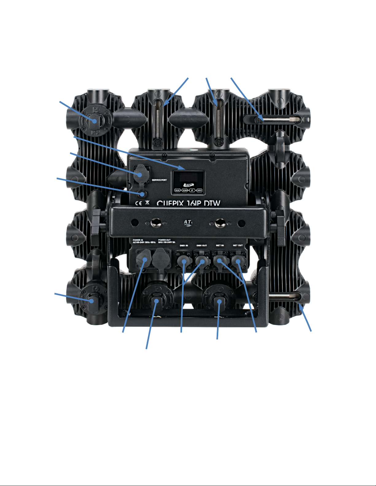
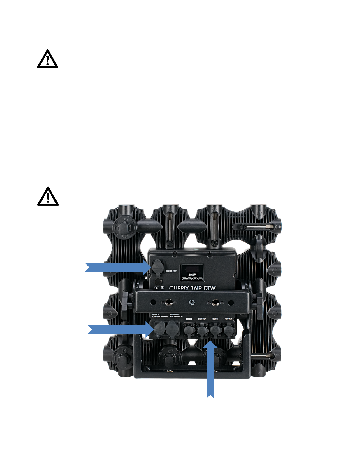
FIXTURE OVERVIEW
Alignment Pins
Interlock
Interlock
LCD Display
Service Port
Air Valve
Interlock
Power
IN/OUT
DMX
IN/OUT
Interlock
NET
IN/OUT
Alignment Pins
9
INSTALLATION INSTRUCTIONS
IP65 RATED
An IP rated lighting fixture is one, which is commonly installed in outdoor environments and has been
designed with an enclosure that effectively protects the ingress (entry) of external foreign objects such as
dust and water. The International Protections (IP) rating system is commonly expressed as “IP” (Ingress
Protection) followed by two numbers (i.e. IP65), where the numbers define the degree of protection. The
first digit (Foreign Bodies Protection) indicates the extent of protection against particles entering the
fixture, and the second digit (Water Protection) indicates the extent of protection against water entering
the fixture. An IP65 rated lighting fixture has been designed and tested to protect against the ingress of
dust (6) and high-pressure water jets from any direction (5).
MARINE/COASTAL ENVIRONMENT INSTALLATIONS
Please note that although this fixture is IP rated, the fixture is NOT suitable for marine and/or coastal
installations. Installing this fixture in a marine and/or coastal environment may cause corrosion and/or
excessive wear to the interior and/or exterior components of the fixture. Damages and/or performance
issues resulting from installation in a marine and/or coastal environment will void the manufacturer’s
warranty and will NOT be subject to any warranty claims and/or repairs.
OPTIONAL CORROSION-RESISTANT COATING
Optional Corrosion-Resistant Coatings may be available for this fixture.
Please contact Elation Professional for more details.
DISCONNECT POWER BEFORE PERFORMING ANY MAINENANCE!
Keep fixture a minimum of 5.0 feet (1.5m) from flammable materials and/or pyrotechnics.
ELECTRICAL CONNECTIONS
A qualified electrician should be used for all electrical connections and/or installations.
ENSURE ALL CONNECTIONS AND END CAPS ARE PROPERLY SEALED WITH A NONCONDUCTIVE DIELECTRIC GREASE (AVAILABLE AT M OS T ELE CTRIC AL SUPPLIERS) TO
PREVENT WATER INGRESS/CONDENSATION AND/OR CORROSION.
USE CAUTION WHEN POWER LINKING OTHER MODEL FIXTURES AS THE POWER
CONSUMPTION OF OTHER MODEL FIXTURES MAY EXCEED THE MAXIMUM POWER
OUTPUT OF THIS FIXTURE. CHECK SILK SCREEN FOR MAXIMUM AMPS.
10
INSTALLATION INSTRUCTIONS
SEAL%ALL%UNUSED%
CONNECTIONCAPS%
SEAL% ALL% UNUSED%
CONNECTIONCAPS%
DO NOT INSTALL THE FIXTURE IF YOU ARE NOT QUALIFIED TO DO SO!
Fixture MUST be installed following all local, national, and country commercial electrical and construction
codes and regulations.
Before rigging/mounting a single fixture or multiple interconnected fixtures for custom matrix designs to
any metal truss/structure or placing the fixture(s) on any surface, a professional equipment installer MUST
be consulted to determine if the metal truss/structure or surface is properly certified to safely hold the
combined weight of the fixture(s), clamps, cables, and accessories.
Fixture ambient operating temperature range is 14° to 113°F (-10° to 45°C).
Do not use the fixture under or above this temperature.
Fixture(s) should be installed in areas outside walking paths, seating areas, or away from areas were
unauthorized personnel might reach the fixture by hand.
NEVER stand directly below the fixture(s) when rigging, removing, or serving.
Overhead fixture installation must always be secured with a secondary safety attachment, such as an
appropriately rated safety cable that can hold 10 times the weight of the fixture.
Allow approximately 15 minutes for the fixture to cool before servicing.
TO MAINTAIN IP65 RATING INTEGRITY, AND PREVENT WATER FROM ENTERING
FIXTURE, ALL UNUSED CONECTION RUPPER CAPS MUST BE SEALED.
11
INSTALLATION INSTRUCTIONS
SAFETY%CABLE%
RIGGING%POINT%
SAFETY%CABLE%
RIGGING%POINT%
YOKE%
HANDLE%KNOB%
YOKE%
HANDLE%KNOB%
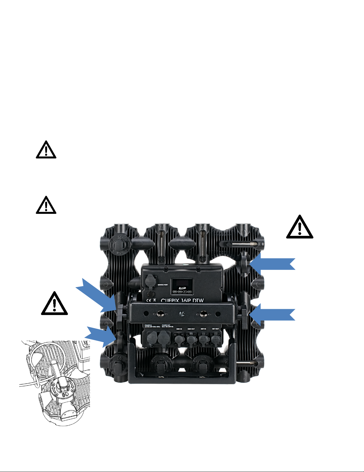
CLAMP MOUNTING
A 90-degree adjustable yoke bracket are attached to the fixture, both include 3-position holes for versatile
fixture positioning. Optional Omega Brackets are available, which can be attached to yoke brackets for
easy clamp-rigging. See the Optional Accessories at the end of this manual for the order code. When
mounting this fixture to truss or a metal structure, be sure to secure an appropriately rated clamp (not
included) to one of the yoke brackets using an M10 screw. Depending on rigging position of the fixture,
it may be best to use more than one clamp attached to the yoke.
WHEN USING THE 90-DEGREE ADJUSTABLE YOKE TO MOUNT THE FIXTURE, MAKE
SURE BOTH YOKE HANDLE KNOBS ARE SECURELY TIGHTENED CLOCKWISE.
SAFETY CABLE
The fixture includes 2 integrated safety cable rigging points. (See image below.)
ALWAYS ATTACH A SAFETY CABLE WHENEVER INSTAL LI NG T HIS FIXT UR E IN A SUSPENDED
ENVIRONMENT TO ENSURE THE FIXTURE WILL NOT DROP IF THE CLAMP FAILS.
12
 Loading...