

Page 1
Transponder Reader
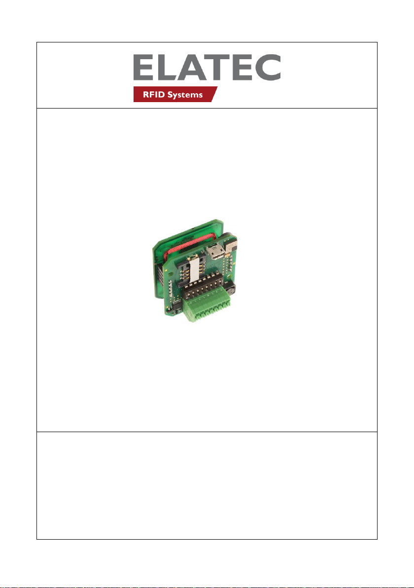
TWN4 Palon Compact
Quick Start Guide
Rev. 6.0
Page 2

Elatec GmbH
1. Introduction
The transponder reader TWN4 Palon Compact is a device for reading and
writing RFID transponders. There are different versions of TWN4 devices
available, which cover a large range of transponder types both in the
frequency range of 125 kHz and 13.56 MHz.
2. Getting Started
2.1 Cable Connection
In order to start operating a TWN4 Palon Compact transponder reader, it
simply has to be connected to a host.
2.2 Power Up
Once a TWN4 Palon Compact reader is connected to the host, it detects
the type of communications cable (USB or RS232), with which it is
connected to the host.
Additionally, the RS232 is sending a version string via RS232 to the host.
Page 2 of 12
Page 3

Elatec GmbH
2.3 Enumeration (USB Only)
This is only applicable for the USB version: Once the device has been
powered up, it is waiting for completion of the enumeration by the USB
host. As long as the device is not enumerated, it is entering a minimum
power consumption mode, where both LEDs are turned off.
2.4 Initialization
After powering up and enumeration (in USB mode), the device is turning on
the built-in transponder reader logic. The green LED is turned on
permanently. Some transponder reader modules need some kind of
initialization, which is performed in this step. After successful initialization,
the device sounds a short sequence, which consists of a lower tone
followed by a higher tone.
2.5 Normal Operation
As soon as the device has completed the initialization, it is entering normal
operation. During normal operation the device is searching for a
transponder continuously.
Page 3 of 12
Page 4

Elatec GmbH
2.6 Detection of a Transponder
If a transponder is detected by the reader, following actions are performed
Send the ID to the host. By default, the USB device sends by
emulating keystrokes of a keyboard. A RS232 device sends the
ASCII code of an ID.
Sound a beep
Turn off the green LED
Blink the red LED for two seconds
Turn on the green LED
Within the two seconds timeout, where the red LED is blinking, the
transponder, which just has been recognized will not be accepted again.
This prevents the reader from sending identical IDs more than one time to
the host.
If during the two seconds timeout of the red LED a different transponder is
detected, the complete sequence restarts immediately.
2.7 Suspend Mode (USB Only)
The USB version of the transponder reader supports the USB suspend
mode. If the USB host is signaling suspend via the USB bus, the
transponder reader is turning off most of its power consuming peripherals.
During this operation mode, no detection of transponders is possible and all
LEDs are turned off.
Once the host is resuming to normal operation mode, this is also signaled
via the USB bus. Therefore, the transponder reader will resume to normal
operation, too.
Page 4 of 12
Page 5

3. List of Antennas
125 kHz
antenna
13.56 MHz
antenna
Elatec GmbH
Page 5 of 12
Page 6

Elatec GmbH
4. Compliance statements
FCC
(RF module)
Compliance statement:
This device complies with Part 15 of the FCC Rules. Operation is subject to
the following two conditions: (1) this device may not cause harmful
interference, and (2) this device must accept any interference received,
including interference that may cause undesired operation.
Modification of equipment:
The instruction manual of the host shall include the following statement:
Changes or modifications made to this equipment not expressly approved
by the party responsible for compliance may void the FCC authorization to
operate this equipment.
Information to the user:
(The instruction manual of the host shall include the following statement) A
compliance statement as applicable, e.g., for devices subject to part 15 of
CFR 47 as specified in §15.19(a)(3), that the product complies with the
rules; and the identification, by name, address and telephone number or
Internet contact information, of the responsible party, as defined in §2.909.
The responsible party for Supplier’s Declaration of Conformity must be
located within the United States.
Page 6 of 12
Page 7

Elatec GmbH
Host devices
FCC notes for a host subject to verification or SDoC:
For a host device assembled with the certified module and subject to 47
CFR Part 15 verification of class A digital devices, the following statements
have to be included in the user manual and the host device has to be
labelled as noted below. If the host device is subject to other authorization
procedures or parts the appropriate requirements of these authorization
procedures or parts apply.
Important note:
OEM integrator is still responsible for the FCC compliance requirements of
the end product, which integrates this module. Appropriate measurements
(e.g. 15B compliance) and if applicable additional equipment authorization
of the host device to be addressed by the integrator/ manufacturer
The end device must be labeled with:
Contains FCC ID: WP5TWN4F10
Contains IC: 7948A-TWN4F10
Page 7 of 12
Page 8

Example for SDoC:
Elatec GmbH
The compliance information statement shall be included in the user's
manual or as a separate sheet. In cases where the manual is provided only
in a form other than paper, such as on a computer disk or over the Internet,
the information required by this section may be included in the manual in
that alternative form, provided the user can reasonably be expected to
have the capability to access information in that form. The information may
be provided electronically as permitted in §2.935.
Page 8 of 12
Page 9

Elatec GmbH
NOTE: The Commission does not have a required SDoC format. This is an
example only and is provided to illustrate the type of information that may
be supplied with the product at the time of marketing or importation for
meeting the FCC SDoC requirement.
For class B devices:
FCC §15.105 (b):
Note: This equipment has been tested and found to comply with the limits
for a Class B digital device, pursuant to part 15 of the FCC Rules. These
limits are designed to provide reasonable protection against harmful
interference in a residential installation. This equipment generates, uses
and can radiate radio frequency energy and, if not installed and used in
accordance with the instructions, may cause harmful interference to radio
communications. However, there is no guarantee that interference will not
occur in a particular installation. If this equipment does cause harmful
interference to radio or television reception, which can be determined by
turning the equipment off and on, the user is encouraged to try to correct
the interference by one or more of the following measures:
- Reorient or relocate the receiving antenna.
- Increase the separation between the equipment and receiver.
- Connect the equipment into an outlet on a circuit different from that
to which the Receiver is connected.
- Consult the dealer or an experienced radio/TV technician for help.
Page 9 of 12
Page 10

Elatec GmbH
For class A devices:
FCC §15.105 (b):
NOTE: This equipment has been tested and found to comply with the limits
for a Class A digital device, pursuant to part 15 of the FCC Rules. These
limits are designed to provide reasonable protection against harmful
interference when the equipment is operated in a commercial environment.
This equipment generates, uses, and can radiate radio frequency energy
and, if not installed and used in accordance with the instruction manual,
may cause harmful interference to radio communications. Operation of this
equipment in a residential area is likely to cause harmful interference in
which case the user will be required to correct the interference at his own
expense.
CANADA:
This device complies with Industry Canada’s license-exempt RSSs.
Operation is subject to the following two conditions:
(1) This device may not cause interference; and
(2) This device must accept any interference, including interference that
may cause undesired operation of the device.
Le présent appareil est conforme aux CNR d’Industrie Canada applicables
aux appareils radio exempts de licence. L’exploitation est autorisée aux
deux conditions suivantes:
1) l’appareil ne doit pas produire de brouillage;
2) l’utilisateur de l’appareil doit accepter tout brouillage radioélectrique subi,
même si le brouillage est susceptible d’en compromettre le fonctionnement.
Special accessories:
Where special accessories such as shielded cables and/or special
connectors are required to comply with the emission limits, the instruction
manual shall include appropriate instructions on the first page of the text
describing the installation of the device.
Simultaneous transmission:
When the host product supports simultaneous-transmission operations the
host manufacturer needs to check if there are additional RF exposure filing
requirements due to the simultaneous transmissions. When additional
application filing for RF exposure compliance demonstration is not required
Page 10 of 12
Page 11

Elatec GmbH
(e. g. the RF module in combination with all simultaneously operating
transmitters complies with the RF
exposure simultaneous transmission SAR test exclusion requirements), the
host manufacturer may do his own evaluation without any filing, using
reasonable engineering judgment and testing for confirming compliance
with out-of-band, restricted band, and spurious emission requirements in
the simultaneous-transmission operating modes. If additional filing is
required please contact the person at ELATEC GmbH responsible for
certification of the RF module.
NCC Warning Statement
低功率電波輻射性電機管理辦法
經型式認證合格之低功率射頻電機,非經許可,公司、商號或使用者均不得
擅自變更頻率、加大功率或變更原設計之特性及功能。
(即低功率電波輻射性電機管理辦法第十二條)
低功率射頻電機之使用不得影響飛航安全及干擾合法通信;經發現有干擾現
象時,應立即停用,並改善至無干擾時方得繼續使用。
前項合法通信,指依電信法規定作業之無線電通信。低功率射頻電機須忍受
合法通信或工業、科學及醫療用電波輻射性電機設備之干擾。
(即低功率電波輻射性電機管理辦法第十四條)
本模組於取得認證後將依規定於模組本體標示審驗合格標籤,
並要求最終產品平台廠商(OEM Integrator)於最終產品平台(End Product)上標
示
”本產品內含射頻模組,其NCC型式認證號碼為:CCXXxxYYyyyZzW ”。
應避免影響附近雷達系統之操作。
Page 11 of 12
Page 12

Elatec GmbH
5. Service Address
In case of any technical questions, please contact:
Elatec GmbH
Zeppelinstr. 1
82178 Puchheim
Germany
Phone: +49 (0) 89 5529961 0
Fax: +49 (0) 89 5529961 129
Email: info-rfid@elatec.com
Page 12 of 12
 Loading...