

Page 1

TCPConv 2
Technical Manual
DocRev11, October 25, 2013
Elatec GmbH
Page 2

Contents
Contents
1. Introduction . . . . . . . . . . . . . . . . . . . . . . . . . . . . . . . . . . . . . . . 4
1.1. Typical Scenario . . . . . . . . . . . . . . . . . . . . . . . . . . . . . . . . . . 4
1.2. Important Features . . . . . . . . . . . . . . . . . . . . . . . . . . . . . . . . . 4
1.3. Software Release History . . . . . . . . . . . . . . . . . . . . . . . . . . . . . 5
2. Hardware Setup . . . . . . . . . . . . . . . . . . . . . . . . . . . . . . . . . . . . . 6
2.1. Connect the network cables . . . . . . . . . . . . . . . . . . . . . . . . . . . . 6
2.2. Plug in the Reader . . . . . . . . . . . . . . . . . . . . . . . . . . . . . . . . . 6
2.3. Power up the TCPConv 2 . . . . . . . . . . . . . . . . . . . . . . . . . . . . . 7
2.4. Network Settings of TCPConv . . . . . . . . . . . . . . . . . . . . . . . . . . . 7
2.4.1. Finding the Devices . . . . . . . . . . . . . . . . . . . . . . . . . . . . 7
2.4.1.1. Requirements . . . . . . . . . . . . . . . . . . . . . . . . . . . 7
2.4.1.2. Start TC2Config . . . . . . . . . . . . . . . . . . . . . . . . . 7
2.4.2. Configure TCPConv and Printer . . . . . . . . . . . . . . . . . . . . . . 8
3. Configuration with Web Frontend . . . . . . . . . . . . . . . . . . . . . . . . . . . . 10
3.1. Interface Setup . . . . . . . . . . . . . . . . . . . . . . . . . . . . . . . . . . . 10
3.1.1. Network Settings . . . . . . . . . . . . . . . . . . . . . . . . . . . . . . 10
3.1.1.1. Hostname Setting . . . . . . . . . . . . . . . . . . . . . . . . 10
3.1.1.2. DHCP Setting . . . . . . . . . . . . . . . . . . . . . . . . . . . 13
3.1.2. USB Settings . . . . . . . . . . . . . . . . . . . . . . . . . . . . . . . . 13
3.1.3. RS232 Settings . . . . . . . . . . . . . . . . . . . . . . . . . . . . . . . 13
3.1.4. Load Default Settings . . . . . . . . . . . . . . . . . . . . . . . . . . . 13
3.2. Change Password . . . . . . . . . . . . . . . . . . . . . . . . . . . . . . . . . 15
3.3. Check Status . . . . . . . . . . . . . . . . . . . . . . . . . . . . . . . . . . . . 15
3.3.1. Version . . . . . . . . . . . . . . . . . . . . . . . . . . . . . . . . . . . 15
3.3.2. Printer . . . . . . . . . . . . . . . . . . . . . . . . . . . . . . . . . . . . 15
3.3.3. USB . . . . . . . . . . . . . . . . . . . . . . . . . . . . . . . . . . . . . 15
3.4. Download Manual . . . . . . . . . . . . . . . . . . . . . . . . . . . . . . . . . 16
4. Change the Software on TCPConv via USB Stick . . . . . . . . . . . . . . . . . . . 17
4.1. Prepare the USB Stick . . . . . . . . . . . . . . . . . . . . . . . . . . . . . . . 17
4.2. Power up TCPConv with USB Stick plugged . . . . . . . . . . . . . . . . . . . 17
5. Diagnose and repair the TCPConv 2 . . . . . . . . . . . . . . . . . . . . . . . . . . 18
5.1. Basic Checks . . . . . . . . . . . . . . . . . . . . . . . . . . . . . . . . . . . 18
5.2. If a TCPConv 2 is no more reachable by TC2Config Tool . . . . . . . . . . . . 18
5.3. If a TCPConv 2 is unable to forward data from reader to TCP/IP connection . . 19
5.4. If a TCPConv works fine, but the printer doesn’t . . . . . . . . . . . . . . . . . 19
5.5. Else ... . . . . . . . . . . . . . . . . . . . . . . . . . . . . . . . . . . . . . . . 20
Page 2 of 23
Page 3

Contents
A. FCC Notice . . . . . . . . . . . . . . . . . . . . . . . . . . . . . . . . . . . . . . . 22
Page 3 of 23
Page 4
1. Introduction
1. Introduction
This document describes all features and the usage of the hardware TCPConv 2. TCPConv
2 is equipped with two USB- and RS232-interface into your local area network (LAN). The
purpose of this hardware is to convert USB or RS232 to Ethernet, in order to provide RS232
or USB devices an extra Ethernet connection.
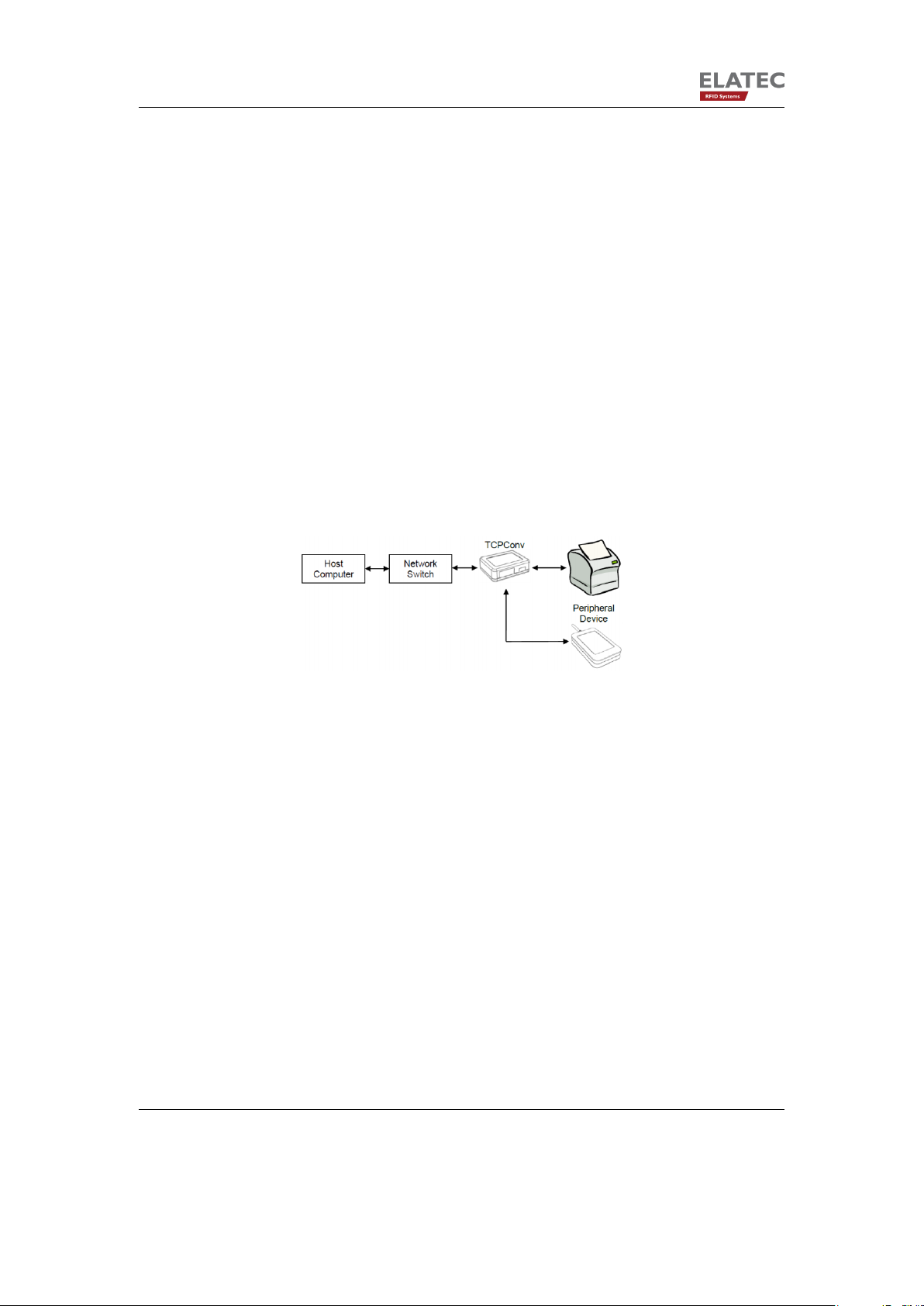
1.1. Typical Scenario
A typical application is the extension of a network device (i.e. a network printer), by a local
peripheral device.
Figure 1.1.: Typical Connection with TCPConv 2, reader and printer
1.2. Important Features
The main feature of TCPConv 2 is that it has the same IP as the printer connected, which
saves a lot of IP resources. This makes TCPConv can be easily integrated into existing
network environments, without managing the extra IP addresses.
The behaviour of TCPConv 2 can be configured via web front-end. Depending on the configuration, it can be a TCP/IP server or client on ports specified by the user.
Except very few ports necessary to configure the TCPConv 2, it is transparent between
printers and local network. Therefore, it is still convenient to configure the printers, as if
TCPConv 2 were not connected in between.
Page 4 of 23
Page 5

1. Introduction
1.3. Software Release History
Version Added Features
SB1.00/STD1.00.02 Initial release
STD1.1.0.0 Improved TCP client behavior
STD1.1.0.2 Log of the application can be viewed via web-frontend
STD1.1.0.4 The hostname of a device can be changed via web-frontend
Page 5 of 23
Page 6
2. Hardware Setup
2. Hardware Setup
2.1. Connect the network cables
There are two Ethernet ports on the TCPConv 2, Host port is used to connect TCPConv 2
to local network and Printer port is used to connect printer to TCPConv 2.
2.2. Plug in the Reader
The user can plug in USB reader directly to the TCPConv 2. Currently HID and CDC devices
are supported.
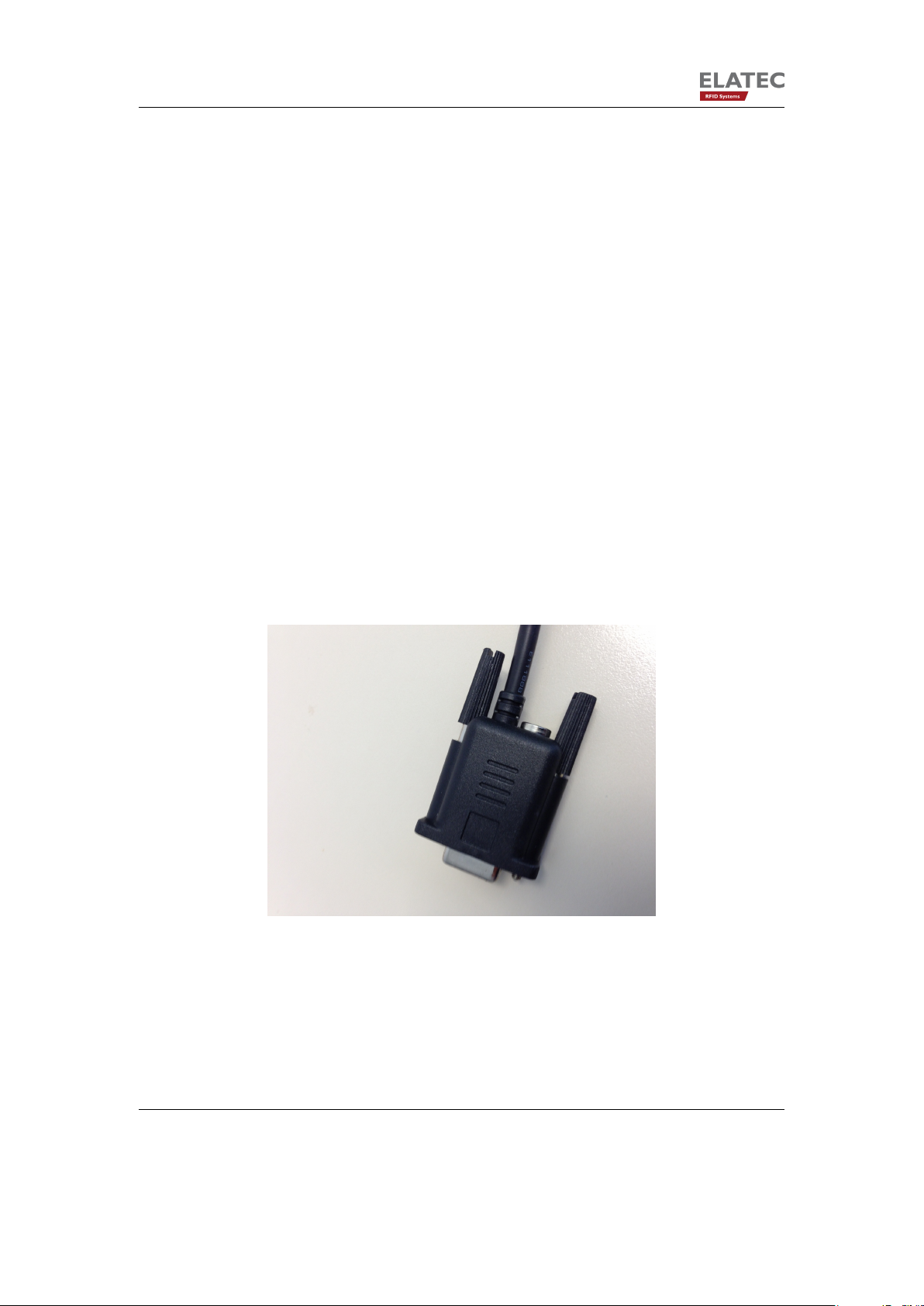
TCPConv 2 can also provide 750mA current from Pin 9 of its RS232 interface. It is undesired
that the RS232 reader is powered by an extra power supply besides TCPConv 2, because it
may potentially damage the TCPConv 2, as well as the external power supply.
Figure 2.1.: RS232 cable with power supply. Please leave the power supply unconnected!
Page 6 of 23
Page 7
2. Hardware Setup
2.3. Power up the TCPConv 2
After the TCPConv 2 is powered up, one can see the status of it via the information LEDs.
There are 4 LEDs on device and several states of the device can be detected based on
combination of LED signals.
• Power LED is ON when power supply is connected.
• Busy LED is red means device is initializing.
• Ready LED is green means device is in normal operation.
• Ready LED is green and Error LED is red means something is wrong, for instance
TCPConv cannot get an IP address.
2.4. Network Settings of TCPConv
2.4.1. Finding the Devices
2.4.1.1. Requirements
1. TC2Config software application
2. Microsoft .Net Framework version 3.5 or higher
3. UDP Port 7001 is available
2.4.1.2. Start TC2Config
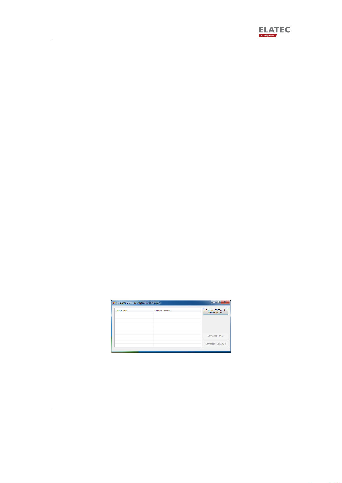
T2Config is a tool which can find all the TCPConv 2 in the local network. By double clicking
the application one can see the following interface:
Figure 2.2.: Interface of TC2Config
To start the search one can simply push the button:
Page 7 of 23
Page 8

2. Hardware Setup
Figure 2.3.: Search for TCPConv
If there are some TCPConv in the network, after a while one can see the whole list:
Figure 2.4.: One TCPConv is found
If the printer connected to the selected TCPConv has web front-end on port 80, one can visit
this page by pushing the button “Connect to Printer”
Figure 2.5.: Visit the web front-end of the printer connected
2.4.2. Configure TCPConv and Printer
In order to reduce the work in network administration, it is recommended to do the following
configurations.
In this example, we assume that the network is 192.168.1.1 and the printer has IP address
of 192.168.1.10.
Page 8 of 23
Page 9

2. Hardware Setup
Figure 2.6.: Network Settings without TCPConv
Now a TCPConv is installed between the switch and the printer. The TCPConv 2 should
now be 192.168.1.10 whereas the printer is located in the private network of TCPConv. The
detailed steps of configuration via web front-end can also be found in Chapter 3.
Figure 2.7.: Network Settings for TCPConv and Printer. Note the TCPConv takes the IP
address that the Printer had.
Figure 2.8.: Sample Network Configuration of TCPConv
Page 9 of 23
Page 10

3. Configuration with Web Frontend
3. Configuration with Web Frontend
3.1. Interface Setup
Figure 3.1.: Visit the web front-end of the selected TCPConv 2
By clicking “Connect to TCPConv” while one device is selected, or by typing <ip of a TCPConv 2>:81 in the browser, one can see the homepage of the TCPConv
By clicking “Setup” in Figure 3.2 and typing in the user name and password, one can change
the configurations. By default, both user name and password are “admin”(without the quotation mark).
The actual settings are displayed on this page. One can for instance configure the TCPConv
to use a static IP address or configure it as TCP Server for USB communication. After
submitting the changes by pushing “Save and Reboot”, TCPConv 2 will apply the changes
and reboot itself.
3.1.1. Network Settings
3.1.1.1. Hostname Setting
One can configure the hostname of a TCPConv 2. If the device uses DHCP, this configured
hostname will be sent to the DHCP server. In order to reach the device via hostname, it is
necessary that the hostname is also registered in DNS server.
Please make sure a valid hostname is given, otherwise TCPConv 2 will ignore the submit.
Page 10 of 23
Page 11

3. Configuration with Web Frontend
Figure 3.2.: Homepage of a TCPConv. Note 192.168.20.246 is also the IP address of this
TCPConv 2
Page 11 of 23
Page 12

3. Configuration with Web Frontend
Figure 3.3.: Page Interface Setup for TCPConv 2
Page 12 of 23
Page 13

3. Configuration with Web Frontend
Hostnames are composed of series of labels concatenated with dots, as are all domain
names. For example, “tcpconv.local” is a hostname. Each label must be between 1 and 63
characters long, and the entire hostname (including the delimiting dots) has a maximum of
255 characters. The Internet standards (Request for Comments) for protocols mandate that
component hostname labels may contain only the ASCII letters ’a’ through ’z’ (in a caseinsensitive manner), the digits ’0’ through ’9’, and the hyphen (’-’). (RFC 1123) permitted
hostname labels to start with digits. No other symbols, punctuation characters, or white
space are permitted.
For German language, this means umlauts (ä, Ä, ö, Ö, ü Ö, ) and ß are not allowed in
hostname.
3.1.1.2. DHCP Setting
One can also activate or deactivate the DHCP on a TCPConv 2 device. A static IP assignment is also possible. If the device fails to get an IP address from DHCP server for some
reason, it will use 192.168.1.1 as default IP address.
3.1.2. USB Settings
Currently TCPConv 2 is able to handle HID and CDC readers. For CDC reader, one can
configure the communication parameters like baudrate, data bits, stop bits etc.
If the TCPConv 2 is configured as server, it is undesired that server port for USB and
for RS232 are the same, because USB server and RS232 server are two different processes.
In the client section, one can configure when the client should be connected. If one wants to
specify the connect char, one should type in the decimal ASCII code for the character. This
rule also applies for “Disconnect on char”. In Figure 3.4 for example, TCPConv 2 configured
in this way will be connected to the server, when the reader sends “0” to TCPConv 2 and it
will be disconnected when it receives carriage return from the reader.
3.1.3. RS232 Settings
The RS232 settings are quite similar to USB settings, as mentioned in last section. Currently
only server function is supported.
3.1.4. Load Default Settings
By pushing “Load Default Settings” one can view the default settings saved in database
on TCPConv. Note that this doesn’t mean the settings are applied, in order to apply the
Page 13 of 23
Page 14

3. Configuration with Web Frontend
Figure 3.4.: Page Interface Setup for TCPConv 2
Page 14 of 23
Page 15

3. Configuration with Web Frontend
changes, one needs to push “Save and Reboot”.
3.2. Change Password
As an administrator one can change the password of the TCPConv. This can be done by
pushing the “Password” tab in Fig 3.2.
It is worthy of being mentioned that only the password is allowed to be changed here for
security reasons.
3.3. Check Status
One can check the running status of TCPConv 2 by clicking “Status”. The status includes
version, printer and USB.
3.3.1. Version
Status Comment
Kernel Linux kernel version, for instance 2.6.35.3-571-
gcca29a0-00017- g2311310
Boot Stream Version of the Boot Stream
File System Version of the File System
3.3.2. Printer
Status Comment
Internal IP Must be in a different network than the TCPConv
Status If there is a printer connected or not
3.3.3. USB
From section USB one can see what kind of USB reader is connected.
Status Comment
CDC Reader connected
HID Keyboard reader connected
USB disconnected Check if the USB reader is connected, also make
sure they are CDC or HID Keyboard Readers
Page 15 of 23
Page 16

3. Configuration with Web Frontend
3.4. Download Manual
This Manual can also be downloaded under “Help”.
Page 16 of 23
Page 17

4. Change the Software on TCPConv via USB Stick
4. Change the Software on TCPConv via
USB Stick
For the configurations mentioned in 3, it is necessary that TCPConv 2 always has a web
front-end accessible by the user. This may not be the case when for example the network
interface on TCPConv 2 is mistakenly configured or an application without web front-end is
for some reason running on TCPConv 2.
Under such circumstances, one can change the software on TCPConv 2 via a USB Stick
with correct software. Here the word “software” can refer to a Linux kernel, a whole Debian
File System, or an application.
4.1. Prepare the USB Stick
The USB Stick should use FAT format, NTFS is not yet supported. It is also desired that the
USB Stick had only one partition. In the coming versions, USB Stick with NTFS and/or more
partitions will also be supported.
The image files can be found under Image of TCPConv2DevPack.
4.2. Power up TCPConv with USB Stick plugged
If the USB Stick plugged has a correct certificate and a correct signature, TCPConv will
execute the main.sh script.
The whole operation could take quite a while when for example the whole File System must
be uploaded to TCPConv. After the script is executed, TCPConv will make a beep and blink
its information LEDs.
Page 17 of 23
Page 18

5. Diagnose and repair the TCPConv 2
5. Diagnose and repair the TCPConv 2
5.1. Basic Checks
In normal operation only Power and Ready LEDs are on(both green). Otherwise please first
make the following checks:
1. If the TCPConv is powered up
2. If the network cables are correctly connected. “Printer” to printer and “Host” to local
network
3. If the Printer is powered up
4. Check if TCPConv can be found by TC2Config Tool
5. Check if the printer uses DHCP to get an IP address
6. Check if the printer uses correct static IP. Normally 192.168.50.100, but 192.168.60.100
in a 192.168.50.x network
5.2. If a TCPConv 2 is no more reachable by TC2Config Tool
Please first do the basic checks as described in the last section, before doing the following
steps.
The Printer port of the TCPConv has always a static IP configured. By default it is 192.168.50.1.
• Connect your PC to Printer port.
• Apply following TCP/IP settings IP address: 192.168.50.100
Netmask: 255.255.255.0
Gateway: 192.168.50.1
Connect to 192.168.50.1:81 via browser and Login screen will appear:
• If there is no connection, apply
IP address: 192.168.60.100
Netmask: 255.255.255.0
Page 18 of 23
Page 19
5. Diagnose and repair the TCPConv 2
Gateway: 192.168.60.1
Connect to 192.168.60.1:81 via browser
• Type in the Username and password
• Fulfil the configuration as explained in 3
• Disconnect PC from Printer port
• Use the normal Hardware Setup
5.3. If a TCPConv 2 is unable to forward data from reader to
TCP/IP connection
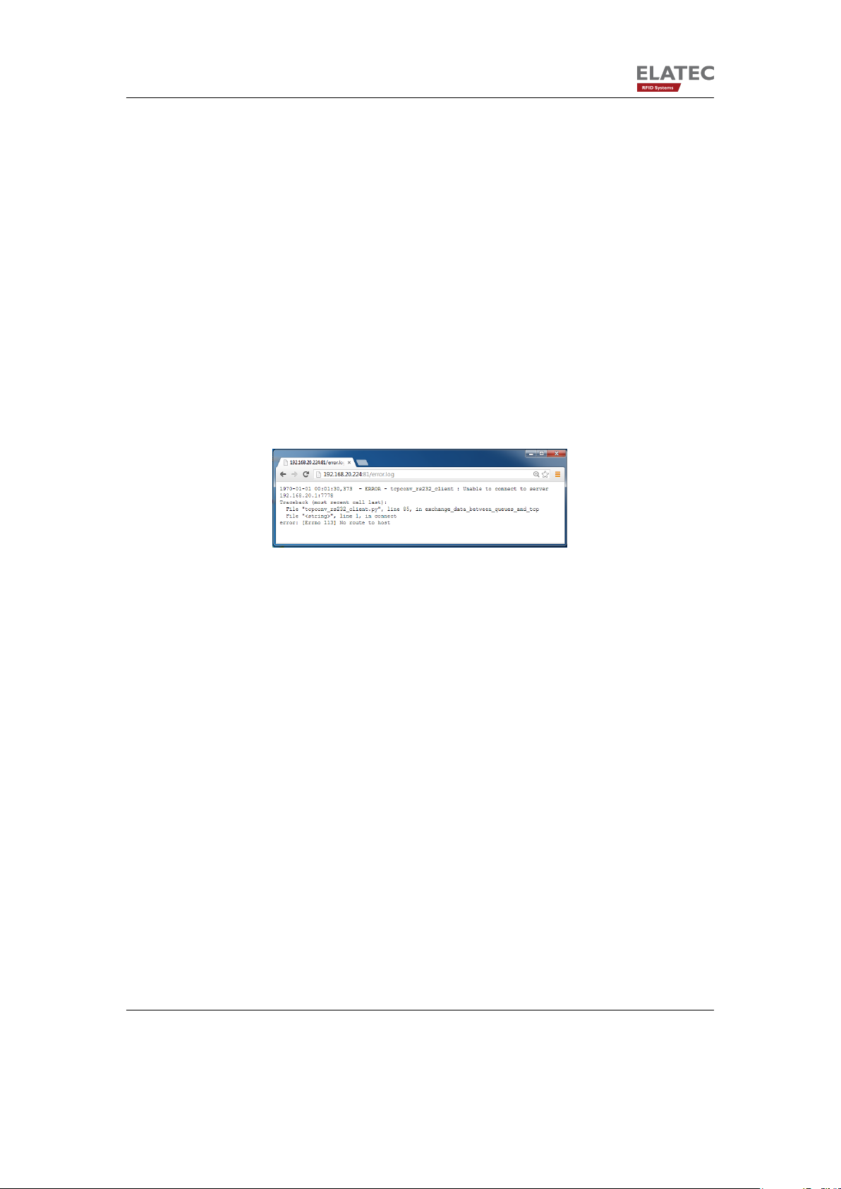
This may be because the TCPConv has a wrong configuration. Under Help->Log file one is
able to see the error log: In Figure 5.1, the TCPConv 2 has no route to the configured server
Figure 5.1.: Sample error log of TCPConv 2
192.168.20.1:7778, as displayed in the browser. Further tracebacks are also be viewed,
which may help the developers to find the bugs as soon as possible.
It is worthy of being mentioned that this log won’t be saved to flash. Therefore, it will be lost
once the TCPConv is rebooted.
5.4. If a TCPConv works fine, but the printer doesn’t
Please first do the basic checks as described in the last section, before doing the following
steps. Meanwhile, please also make sure that the printer itself works fine if it is directly
connected to the local network without a TCPConv 2 in between.
The reason for this can the following:
• The printer uses the same TCP port that TCPConv uses.
This will be a problem because they share the same IP address. If this is the case,
please go to the Interface Setup page and configure the TCPConv 2.
Page 19 of 23
Page 20

5. Diagnose and repair the TCPConv 2
• The printer itself has problems to print, for instance no paper, no ink.
Figure 5.2.: Modify the local port for USB communication
5.5. Else ...
Please contact support-rfid@elatec.com for an image. Copy the image to the root directory
of USB Flash, plug in the USB Flash to the TCPConv 2 and then reboot the TCPConv
2.
Page 20 of 23
Page 21

5. Diagnose and repair the TCPConv 2
Figure 5.3.: Modify the local port for RS232 communication
Page 21 of 23
Page 22

A. FCC Notice
A. FCC Notice
NOTICE
This device complies with Part 15 of the FCC Rules.
Operation is subject to the following two conditions:
1. this device may not cause harmful interference, and
2. this device must accept any interference received, including interference that may cause undesired operation.
NOTICE
Changes or modifications made to this equipment not expressly approved by Manufacturer may void the FCC authorization to operate
this equipment.
NOTE
This equipment has been tested and found to comply with the limits for a Class B digital
device, pursuant to Part 15 of the FCC Rules. These limits are designed to provide reasonable protection against harmful interference in a residential installation. This equipment
generates, uses and can radiate radio frequency energy and, if not installed and used in
accordance with the instructions, may cause harmful interference to radio communications.
However, there is no guarantee that interference will not occur in a particular installation. If
this equipment does cause harmful interference to radio or television reception, which can
be determined by turning the equipment off and on, the user is encouraged to try to correct
the interference by one or more of the following measures:
• Reorient or relocate the receiving antenna.
Page 22 of 23
Page 23

A. FCC Notice
• Increase the separation between the equipment and receiver.
• Connect the equipment into an outlet on a circuit different from that to which the receiver is connected.
Consult the dealer or an experienced radio/TV technician for help.
Page 23 of 23
 Loading...