

Page 1

Page 2

Elastix SIP Firewall
User Manual
Page 3

1
Copy Right
Copyright © 2014 Elastix®. All rights reserved.
No part of this publication may be copied, distributed, transmitted, transcribed, stored in a retrieval system,
or translated into any human or computer language without the prior written permission of
http://www.elastix.org. This document has been prepared for use by professional and properly trained
personnel, and the customer assumes full responsibility when using it.
Proprietary Rights
The information in this document is Confidential to Elastix® and is legally privileged. The information and
this document are intended solely for the addressee. Use of this document by anyone else for any other
purpose is unauthorized. If you are not the intended recipient, any disclosure, copying, or distribution of this
information is prohibited and unlawful.
Disclaimer
Information in this document is subject to change without notice and should not be construed as a
commitment on the part of http://www.elastix.org. And does not assume any responsibility or make any
warranty against errors. It may appear in this document and disclaims any implied warranty of
merchantability or fitness for a particular purpose.
!
!
!
Page 4
2
1.1. About this manual
This manual describes the Elastix® product application and explains how to work and use
it major features. It serves as a means to describe the user interface and how to use it to
accomplish common tasks. This manual also describes the underlying assumptions and
users make the underlying data model.
1.1. Document Conventions
In this manual, certain words are represented in different fonts, typefaces, sizes, and
weights. This highlighting is systematic; different words are represented in the same style
to indicate their inclusion in a specific category. Additionally, this document has different
strategies to draw User attention to certain pieces of information. In order of how critical
the information is to your system, these items are marked as a note, tip, important,
caution, or warning.
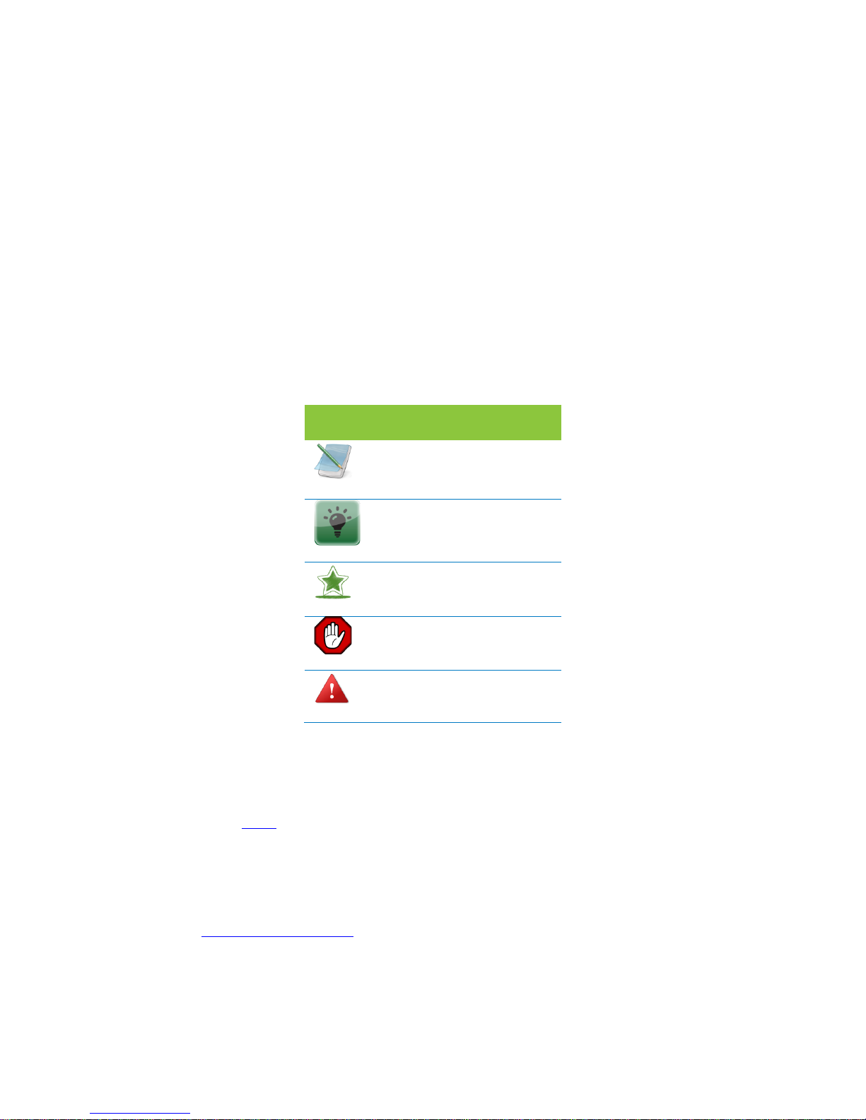
Icon!
Purpose!
!
Note!
!
Tip/Best!Practice!
!
Important!
!
Caution!
!
Warning!
!
!
• Bold indicates the name of the menu items, options, dialog boxes, windows and
functions.
• The color blue with underline is used to indicate cross-references and hyperlinks.
• Numbered Paragraphs - Numbered paragraphs are used to indicate tasks that need
to be carried out. Text in paragraphs without numbering represents ordinary
information.
• The Courier font indicates a command sequence, file type, URL, Folder/File name
e.g. http://www.elastix.org
Page 5

3
1.2. Support Information
Every effort has been made to ensure the accuracy of the document. If you have
comments, questions, or ideas regarding the document contact:
sales@elastix.com
!
!
!
!
!
!
!
!
!
!
!
!
!
!
!
!
!
!
!
!
Page 6

4
Table of Contents
About this manual .................................................................................................. 2
Document Conventions ........................................................................................... 2
Support Information ............................................................................................... 3
1. Introduction ........................................................................................................... 6
1.1. Overview: ......................................................................................................... 6
1.1.1. Notification LEDs (On the Front Panel of the SIP Firewall) ........................ 8
1.1.2. SIP Firewall Rear View: .............................................................................. 9
1.1.3. SIP Firewall Deployment Considerations ................................................... 9
2. Initial Setup & Configuration .............................................................................. 11
2.1.Default Configuration ...................................................................................... 11
2.2. Accessing the WebUI ..................................................................................... 11
2.4 WebUI Session timeout .................................................................................. 14
2.5 WebUI Settings ............................................................................................... 14
2.4 Dashboard ...................................................................................................... 15
3. Device Configuration .......................................................................................... 16
3.1. General Settings ............................................................................................ 17
3.2. Time Settings ................................................................................................. 18
3.3. Management Access ..................................................................................... 18
3.4. Signature Update ........................................................................................... 20
3.5. Logging .......................................................................................................... 20
4. Configuring the SIP Security Policies ............................................................... 22
4.1. SIP Attacks Detection Policies ....................................................................... 22
4.2. SIP Protocol Compliance ............................................................................... 24
4.3. Firewall Rules ................................................................................................ 26
4.4. Firewall Settings ............................................................................................. 27
4.5. White list Rules .............................................................................................. 28
4.6. Blacklist Rules (Static) ................................................................................... 29
4.7. Dynamic Blacklist Rules ................................................................................. 30
4.8. Geo IP Filter ................................................................................................... 30
Page 7

5
5. Status ................................................................................................................... 32
5.1. Security Alerts ................................................................................................ 32
6. Tools ..................................................................................................................... 33
6.1. Administration ................................................................................................ 33
6.2. Diagnostics .................................................................................................... 34
6.3. Ping ................................................................................................................ 35
6.4. Trace route ..................................................................................................... 35
6.5. Troubleshooting ............................................................................................. 36
6.6. Firmware Upgrade ......................................................................................... 37
6.7. Logs Archive .................................................................................................. 38
7. Appendix A – Using Console Access ............................................................... 39
8. Appendix B – Configuring SIP Firewall IP Address via Console .................... 40
Page 8

6
1. Introduction
1.1 . Overview:
This User manual describes the steps involved in setting up the Elastix® SIP Firewall
Appliance. Elastix® SIP Firewall is an appliance based VoIP threat prevention solution
dedicated to protect the SIP based PBX/Telecom Gateway/IP Phones/Mobile device
deployments. The appliance runs the Real time Deep Packet Inspection on the SIP
traffic to identify the VOIP attack vectors and prevents the threats impacting the SIP
based devices. The appliance has been made to seamlessly integrate with the existing
network infrastructure and reduces the complexity of deployment.
The appliance feature set includes,
! Analyze SIP packets using the Realtime Deep Packet inspection engine.
! SIP Protocol Anomaly detection with configurability of detection parameters.
! Detection and Prevention of the following categories of SIP based Attacks.
• Reconnaissance attacks (SIP Devices Fingerprinting, User enumeration,
Password Cracking Attempt)
• Dos/DDos Attacks
• Cross Site Scripting based attacks.
• Buffer overflow attacks
• SIP Anomaly based attacks
• 3rd Party vendor vulnerabilities
• Toll Fraud detection and prevention
• Protection against VOIP Spam & War Dialing
! Attack response includes the option for quietly dropping malicious SIP packets to
help prevent continued attacks
! Dynamic Blacklist Update service for VOIP, SIP PBX/Gateway Threats
! Configurability of Blacklist/White list/Firewall rules.
! Support for Geo Location based blocking.
! Provide the option to secure against PBX Application vulnerabilities
! Operate at Layer 2 device thus transparent to existing IP infrastructure - no changes
required to add the device to your existing network
! Web/SSL based Device Management Access which will allow managing the device
anywhere from the Cloud.
! Ability to restrict the device management access to specific IP/Network.
! Provide System Status/Security events logging option to a remote Syslog server.
! Provides the SIP throughput up to ~10Mbps.
! Support for Signature update subscription and automated signature update
mechanism.
Page 9

7
! The device has been made to operate with default configuration with just powering
on the device. No administrator intervention is required to operate the device with
default configuration.
! USB based power supply
! Optional support for security events logging on the USB based storage.
Technical Specifications
Functional Mode
Transparent Firewall with SIP Deep Packet
Engine.
SIP Intrusion/Prevention
~400+ SIP Attack Signatures Support
Throughput
~10Mbps
No of concurrent calls supports
Up to 50 concurrent calls
Logging
Local Security Event Console, Remote Syslog
Device Management
Web GUI via Https & SSH CLI
Hardware
MIPS based 32bit Processor Single core,
300MHz
Primary Storage
16 MB Flash
RAM
64MB
Secondary Storage
USB Storage devices support for logging (
Optional)
Interfaces
Two Fast Ethernet Interfaces.
Page 10

8
1.1.1. Notification LEDs (On the Front Panel of the SIP Firewall)
LED 4-Alert Status
Power ON/OFF LED 3-DPI Status
Button
LED 2- Interface Status
Power LED LED 1- System Status
Indicator
Figure 1: Front Panel LED Notifications
The SIP Firewall package includes:
• 1 SIP Firewall Appliance
• 1 USB Power Adapter
• 1 Serial Console Cable
• 2 Ethernet Cables
Page 11
9
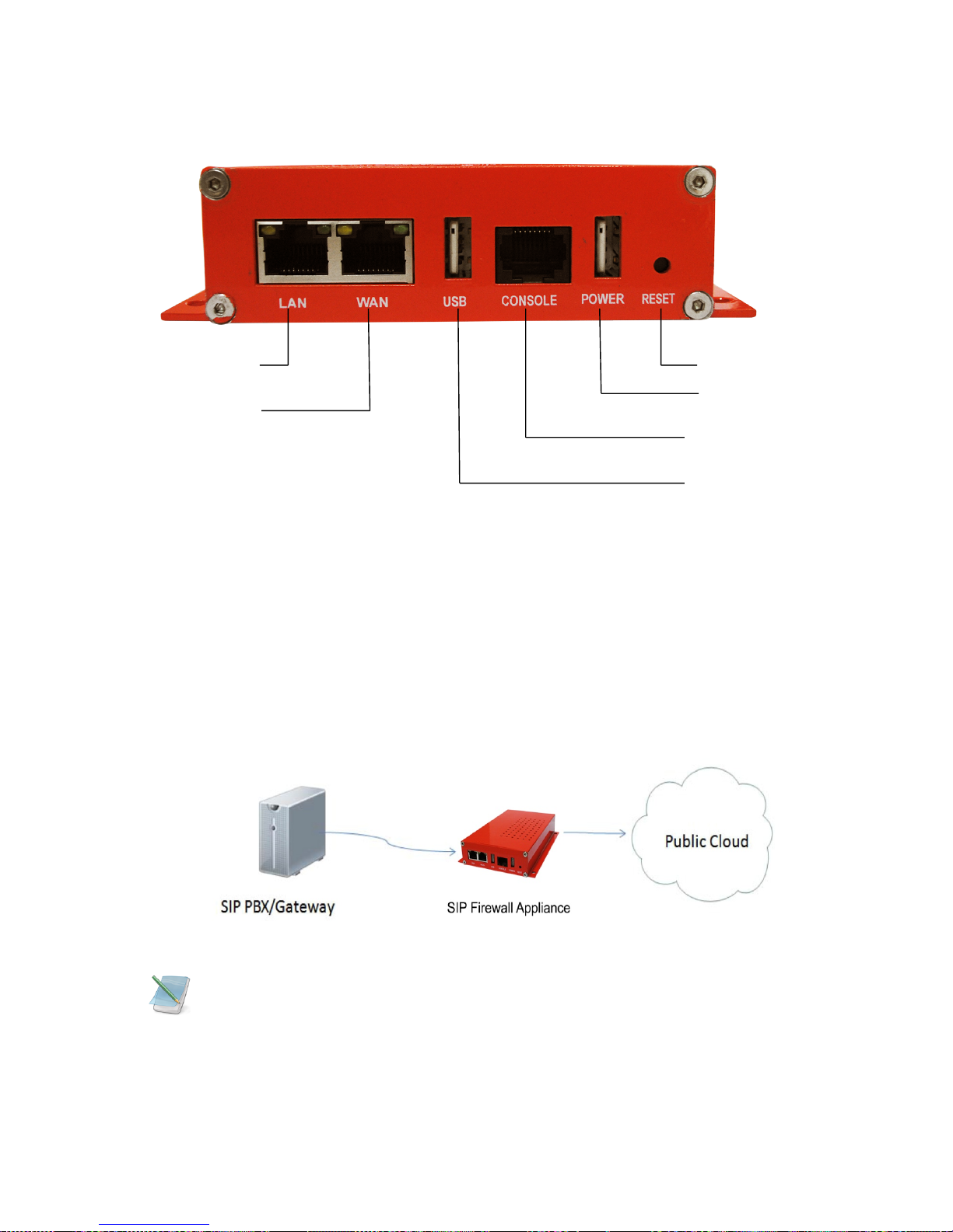
1.1.2. SIP Firewall Rear View:
LAN Port Reset Button
WAN Port USB Power Plug
Console Port
USB Storage Plug
Figure 2: SIP Firewall Rear View
1.1.3. SIP Firewall Deployment Considerations
The SIP Firewall has been made to protect the SIP based PBX/Gateway Servers against
SIP based network threats and anomalies. Thus it is recommended to deploy the SIP
Firewall along with the PBX/Gateway deployment as given in the following scenarios
based on what is applicable in the user’s setup.
Deployment Scenario 1
Figure 1: Scenario 1
Some of the PBX/Gateway devices may have an exclusive LAN/Mgmt Interface for
device management purpose other than the Data Interface (also referred as WAN/Public
Interface). In such cases LAN Port of the SIP Firewall should be connected to the Data
Interface (WAN/Public Interface).
Page 12
10
Deployment Scenario 2
In the case of IPPBX deployed in the LAN Setup, the following setup is recommended as
it would help to protect against the threats from both Internal Network as well as the
threats from the Public Cloud penetrated the Non SIP aware Corporate Firewall.
Figure 2: Scenario 2
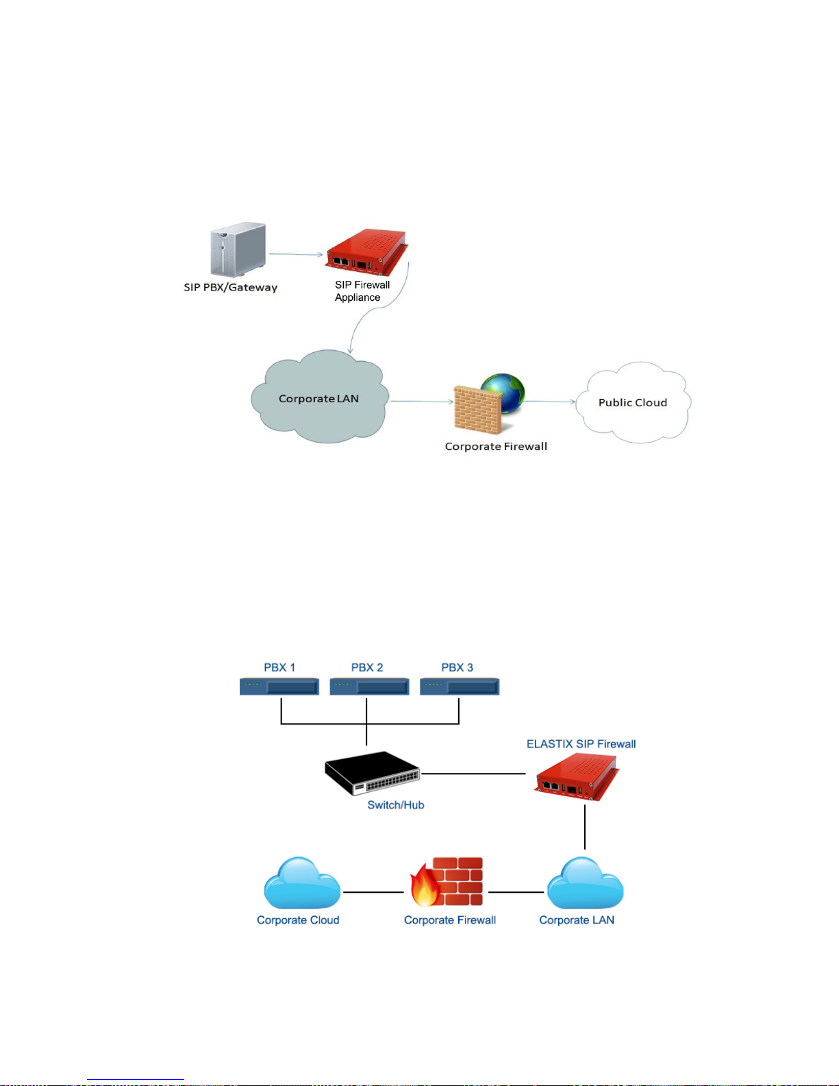
Deployment Scenario 3
In the case of multiple IPPBX/ VOIP Gateways are deployed in the LAN Setup, the
following setup is recommended as it would help to protect against the threats from both
Internal Network as well as the threats from the Public Cloud penetrated the Non SIP
aware Corporate Firewall.
Figure 3: Scenario 3
Page 13

11
2. Initial Setup & Configuration
1. Unpack the items from the box
2. Check that you have all the items listed in the package content.
3. Connect the WAN port of the SIP Firewall to the untrusted/public network.
4. Connect the LAN port of the SIP Firewall to the PBX/VOIP Gateway.
5. Connect the appliance to the power socket using the USB power cable.
6. The device will take about a minute to boot up & will be fully functional with the
default configuration.
Some of the PBX/Gateway devices may have an exclusive LAN/Mgmt Interface for
device management purpose other than the Data Interface (also referred as WAN/ public
Interface). In such cases LAN port of the SIP Firewall should be connected to the Data
Interface (WAN/ Public Interface).
2.1 .Default Configuration
The device operates as a transparent bridging firewall with Deep Packet Inspection
enabled on the SIP traffic. By default, the appliance has been configured with static IP of
10.0.0.1 (Net mask 255.255.255.0)
The device has been made to be fully functional with the default configuration. However if
the user needs to tune the device settings & the DPI policies, user can tune the
configuration via the Device WebUI.
The device all provides the command line interface accessible via SSH, which will allow
to configure the basic settings and view device status.
Management Access
Login Credentials
WebUI
admin/admin
SSH CLI
admin/stmadmin
Management Vlan IP
192.168.100.1/255.255.255.0
Default Device IP
10.0.0.1/255.255.255.0
2.2. Accessing the WebUI
The user can connect to the device via management Vlan to access WebUI during initial
setup. The management Vlan configured on the device, is accessible via the LAN/WAN
ports & is made assigned to the default IP address ‘192.168.100.1’
Page 14

12
Use the procedure given below to access the WebUI,
1. Connect the LAN port of the SIP Firewall to a PC.
2. Assign the IP Address 192.168.100.2 to the PC. Set the Net mask as
255.255.255.0.
Now you can access the device from the browser using the URL https://<192.168.100.1>
Configure the SIP Firewall Device IP Address from the “Device Settings” Page as per
your local network range. Verify the IP address set to SIP Firewall from the dashboard
page. Once the user assigns the SIP Firewall Device IP Address successfully, he can
access the device using that IP address further.
Now he can disconnect the PC and connect the LAN Port to the PBX/PBX Network that
needs to be protected.
The WebUI has been made accessible only via HTTPS. The recommended
browser for accessing SIP Firewall WebUI is Mozilla Firefox.
The UI allows the administrator to configure the management Vlan IP addresses. In
case if the user has changed the management Vlan IP address, he needs to assign the
corresponding network address to his PC for the management access subsequently.
On launching the SIP Firewall WebUI, the web application will prompt to enter the
administrator credentials to login.
Alternatively the user can access the device via the static IP 10.0.0.1 and configure
the network settings during first time installation. Connect a PC to the LAN port of the SIP
Firewall and assign the IP address 10.0.0.100/255.255.255.0 to the PC. Now you can
access the device from the browser using the URL https://<10.0.0.1>
If the device is not accessible after configuring the new network configuration, Try
rebooting the device and check the device dashboard accessing via Management Vlan.
Page 15

13
Figure 4: Login Page
The WebUI login session has been made to time out and if the user does not enter the
login credentials for 30 seconds and will redirect to the informational page. The user can
click the hyperlink named as ‘login’ appearing on the information page, to visit the login
page again.
Figure 5: Timeout message
If somebody is already logged in to SIP Firewall WebUI session, the subsequent attempts
to login will notify the details previous login session as illustrated below and will prompt
the user to override the previous session and continue OR to discard the attempt the
login.
Page 16

14
Figure 6: Select Login attempt
2.4 WebUI Session timeout
After logging into the WebUI, if there is no activity until the WebUI session timeout period
(By default, the WebUI session timeout is set to 900 seconds), then the login session will
automatically terminated and browser will be redirected to login page again.
2.5 WebUI Settings
To change the WebUI settings, click the settings icon that appears top right corner (below
the Apply Changes button). The WebUI settings dialog will be displayed in the browser
and allow the administrator to configure WebUI session timeout & WebUI login password.
To configure the WebUI login password, the user needs to enter the previously set
administrator password.
Figure 7: WebUI Settings
Page 17

15
2.4 Dashboard
Figure 8: Dashboard
On logging into the SIP Firewall WebUI, the dashboard will be shown.
The user can visit the dashboard page from the any configuration page in the SIP Firewall
WebUI, by clicking the SIP Firewall Product Icon that appears in the left corner of the Top
panel.
The status panel that appears below the top panel shows the time settings on the device
and SIP Firewall firmware version, Page refresh icon and Setting icon.
On clicking the page refresh button, the main content area in the current page will be
refreshed.
On clicking the settings icon, the pop menu which contains menu options logout, WebUI
settings will be shown.
System Status Panel shows Device up time, Memory Usage, Flash Usage & CPU Usage.
Sig Update Version Panel shows the SIP Firewall Signature version and Release State.
Network Status Panel shows IP, LAN MAC, WAN MAC and Gateway of the device.
Security Alert Summary Panel shows hyperlinks for viewing of Top 10 Signatures hit, Top
10 Categories hit, Top Attacker IP Addresses & Top 10 target destinations.
Page 18

16
3. Device Configuration
Configuration pages of the SIP Firewall WebUI have been made as self- intuitive and
easy to configure.
All the configuration pages have been made to work with the two-phase commit model.
The two-phase commit model is not applicable to time settings and signature
update settings. In these settings, the changes will be applied directly by clicking the
‘Apply’ in the content area of the configuration editor.
I.e. When the administrator changes the settings in the configuration pages and click the
Save button, the settings will be saved in a temporary buffer location on the device. On
saving the configuration changes, the ‘Apply Changes’ button that appears in the right top
corner will be enabled & the ‘Ignore Changes’ button will appear next.
Figure 9: Device Configuration
The number of configuration changes will appear on the immediate left to the ‘Apply
Changes’ button. To view the details of the configuration changes, the user can click the
number icon, which will open the configuration changes listing.
The user can apply the configuration changes to the device, by clicking ‘Apply Changes’
button. On clicking the ‘Apply Changes’ button, the configuration changes will be applied
to the system and updated configuration will be persisted permanently onto the device.
Page 19

17
In case if the user wants to abandon the configuration changes made, he can click the
Ignore Changes button. On clicking the ‘Ignore Changes’ button, the configuration
changes stored in the temporary buffer location will be discarded.
To apply the configuration changes, the ‘Ignore Changes’ button will be displayed
and they cannot choose to ignore configuration changes. The ‘Ignore Changes’ button will
be disabled, only when there are pending configuration changes that need to be applied
yet to the device.
If the administrator tries to configure a configuration element to the inappropriate
value, the tooltip icon that appears next to each configuration element will provide the
details on the error.
On clicking the help icon that appears next to the configuration title, the help section
corresponds the current configuration page will be launched.
3.1. General Settings
The General settings page will allow configuring the host/network settings of the SIP
Firewall appliance. The device that has been made to work in bridging mode can either
choose to work with static IP assignment or to acquire the device IP via DHCP.
The page also allows to enable/disable the SSH Access to the device. The ‘Allow ICMP’
option will configure the device to respond to the ICMP ping messages sent to SIP Firewall
appliances or not.
By the SSH Access and ICMP Ping messages are allowed to the SIP Firewall appliance.
Figure 10: General Settings
Page 20

18
3.2. Time Settings
The administrator can choose to set the manual time settings on the device or configure
the device to sync the time settings from an NTP server. Appropriate time settings/time
zone should be set on the device to the correct timestamp to appear on the SIP security
alerts generated by the device.
Figure 11: Date/Time Settings
3.3. Management Access
The access the SIP Firewall Device management (SSH CLI / WebUI Access) can be
restricted with the management access filters. By default, the access has been allowed to
any global address and management VLAN network configurations on the device. The
administrator can override these settings.
Page 21

19
Figure 12: Create Management Access Rule
Figure 13: Management access
The administrator needs to configure the IP Address or the IP Network or the Range of IP
Addresses from with management access to the device should be allowed in the
management access filter rule. The IP Type ‘ANY’ indicates global networks (Any
network/IP address).
The search option in the management access filters table will help in selectively viewing
the management access filter rules whose name/address values that match with the
search criteria.
Page 22

20
3.4. Signature Update
To enable the automatic signature update, select the checkbox ‘enable update’ on the
device and configure the signature update schedule. The valid subscription key and
correct signature update URL should be configured for the signature update to happen.
To update the signatures on the device instantaneously, Click ‘Update Signatures now’
button.
Figure 14: Signature Update
When the user buys the SIP Firewall appliance, the device will be shipped with the
SIP signatures that will help in protecting against the SIP based attacks known as of date.
However, if the user wants to ensure their SIP deployments get the protection against the
newest attack vectors, it is recommended to enable the signature update on the device.
Please check with an Elastix’s Sales representative about getting the details of
purchasing the SIP Firewall signature subscription key.
3.5. Logging
The administrator can configure the SIP Firewall appliance to send the security alerts
generated on detecting the SIP based attacks, to the remote SYSLOG server.
The logging page will allow enable/disable the remote logging of security alerts and to
which SYSLOG server the security alerts are to be forwarded.
Page 23

21
Figure 15: Logging
Page 24

22
4. Configuring the SIP Security Policies
4.1. SIP Attacks Detection Policies
The SIP Attack Detection page allows to configure the SIP Deep packet Inspection rules
categories. The administrator can enable/disable the inspection against a particular
category of rules, action to be taken on detecting attacks matching the rules in the
categories.
The possible actions that the SIP Firewall can execute are logging the alert, block the
packets containing the attack vector and blacklist the attacker IP for the given duration.
The blocking duration of how long the attacker up needs to be blocked is also configured
per category level.
Figure 16: SIP Attacks Detection
The table given below lists the SIP Deep packet Inspection rules categories supported in
SIP Firewall and configuration parameters in each category.
Page 25

23
Category
Description
User Configurable
options
SIP
Reconnaissance
Attacks
The intruder is trying to detect what
version of Asterisk you are running.
With that info, he will start exploiting
the numerous vulnerabilities of that
version. The SIP Firewall will not
respond to his query.
N/A
SIP Devices
Scanning
The intruder will scan the PBX ports to
see what devices are connected to it.
With that info, he can exploit 3rd party
vulnerabilities. The SIP Firewall will not
respond to his query.
N/A
SIP Extensions
Discovery
The intruder will ask the PBX to
divulge the range of the extension
numbers. With that info, he can try
different passwords to take control of
these extensions. The SIP Firewall will
not respond to that query.
Invalid SIP User
Registration
Attempts/Duration
Multiple
Authentication
Failures/Brute force
password Attempt
The intruder will try to log in with
different user names and passwords
multiple times. Once he succeeds, he
will have control of that extension. The
SIP Firewall can block, log or blacklist
the IP for a period of time if it exceeds
the authorized number of trials/second.
Failed Authentication
Attempts/Duration
Ghost calls Attempt
The intruder will generate calls to an
extension and it will look like the calls
come from that same extension. His
goal is to crash the PBX resulting in
disrupted communication. The SIP
Firewall can block, log or blacklist the
IP for a period of time if it exceeds the
authorized number of trials/second.
No of Anonymous
Invite
Responses/Duration
SIP Dos Attacks
Flooding attempts using various SIP
messages.
No of SIP Request
Messages/Duration
SIP DDos Attacks
Distributed flooding attempts using
various SIP messages.
No of SIP Response
Messages/Duration
SIP Anomaly
attacks
The intruder will send abnormal SIP
packets to the PBX. His goal is to
crash the PBX resulting in disrupted
N/A
Page 26

24
communication. The SIP Firewall can
block, log or blacklist the IP for a
period of time if it exceeds the
authorized number of trials/second.
SIP Buffer overflow
attacks
Buffer overflow attempts resulted from
improper validation of user inputs.
N/A
SIP Cross site scripting
SIP is vulnerable to cross-site
scripting, caused by improper
validation of user-supplied input in a
SIP request. A remote attacker could
exploit this vulnerability to inject
malicious script into a Web page which
would be executed in a victim's Web
browser, when the victim accessed a
web page containing information taken
from the SIP request.
N/A
3rd Party vendor
vulnerabilities
Attacks targeted towards PBX/SIP
Gateway appliances exploiting their
vulnerabilities.
N/A
4.2. SIP Protocol Compliance
The SIP Deep packet inspection engine running the SIP Firewall appliance has been
made to inspect the SIP traffic with the SIP Security Compliance rules in built into the SIP
DPI engine.
The anomalies in the SIP Message headers can result to various erroneous conditions,
SIP parser failures & malformed packets which will lead to SIP applications vulnerable to
attacks.
The following parameters will be used by the SIP deep packet engine for identifying the
different protocol anomaly conditions and take the action configured by the administrator.
Configuring inappropriate values for these parameters can result to the disruptive
impact in the VOIP deployment. Administrators with more in-depth understanding with the
SIP protocol can choose to tune these parameters for their specific deployment needs.
Otherwise, recommended to use the default settings for these parameters.
Page 27

25
Figure 17: SIP Protocol Compliance
Max_sessions
A SIP session is the application level connection setup created between the SIP server
and SIP client for exchanging the audio/video messages with each other.
The max_sessions parameter defines the maximum number session that SIP deep
packet inspection engine can keep track of. The default value has been set at 4096.
Max Dialogs per session
Max_Dialogs_per_session specifies the maximum number of SIP message transaction
that can happen between the SIP server and client.
Methods
This specifies on what methods to check for SIP messages.
The Following are the SIP messages that SIP DPI Engine can identify: (1) invite, (2)
cancel, (3) ack, (4) bye, (5) register, (6) options, (7) refer, (8) subscribe, (9) update (10)
join (11) info (12) message (13) notify (14) prack.
Max_uri_len
The Uri identifies the user or service to which SIP request is being addressed.
Max_uri_len specifies the maximum Request URI field size. The Default is set to 256. The
allowed range for this option is 1 - 65535.
Max_call_id_len
The Call-ID header field in SIP message acts as a unique identifier that relates to
sequence of messages exchanged between SIP client and server. Max_call_id_len
specifies the maximum Call-ID field size. The Default is set to 256. The allowed range for
this option is 1 - 65535.
Page 28

26
Max_requestName_len
Max_requestName_len specifies the maximum request name size that is part of the CSeq
ID. The Default is set to 20. The allowed range for this option is 1 - 65535
Max_from_len
The From header field indicates the identity of the initiator of the SIP request.
Max_from_len specifies the maximum from field size. The allowed range for this option is
1 - 65535.
Max_to_len
The to header field specifies the desired recipient of the SIP request. Max_to_len
specifies the maximum to field size. The Default is set to 256. The allowed range for this
option is 1 - 65535.
Max_via_len
The Via header field indicates the transport used for the SIP transaction & identifies the
location where the SIP response is to be sent.
Max_via_len specifies the maximum Via field size. The Default is set to 1024. The
allowed range for this option is 1 - 65535.
Max_contact_len
The Identifier used to contact that specific instance of the SIP client/server for subsequent
requests. Max_contact_len specifies the maximum Contact field size. The Default is set to
256. The allowed range for this option is 1 - 65535.
Max_content_len
Max_content_len specifies the maximum content length of the message body. The
Default is set to 1024. The allowed range for this option is 1 - 65535.
4.3. Firewall Rules
The firewall rules configuration will allow the administrator in configuring what traffic
should be allowed to protect SIP PBX/Gateway network from an untrusted wan zone,
besides DPI enabled SIP traffic and RTP traffic. The administrator needs to specify the
source and destination networks and port numbers and protocol that will be used as the
matching criteria in the filtering rules and action to be taken on matching the filtering rule.
The possible actions are to block the traffic and allow the traffic on matching the filtering
rule. The rules precedence will be in the order in which the rules configured on firewall
rules table.
Page 29

27
Figure 18: Create Firewall Rule
4.4. Firewall Settings
Firewall Settings allows user to configure TCP Flood Rate, TCP Flood Burst, UDP
Flood rate and UDP Flood Burst in Global firewall settings.
Figure 19: Firewall Settings
Page 30

28
4.5. White list Rules
This page allows to configure the white listed IP addresses in the untrusted wan zone
from which the access to communicate with the protected SIP network will be allowed by
the SIP Firewall.
This page will also allow configuring whether the white rules take precedence over the
blacklist rules (both static and dynamic) configured on the device at any instant.
Figure 20: Create White list Rule
Figure 21: White list IP Addresses
Page 31

29
4.6. Blacklist Rules (Static)
This page allows to configure the blacklisted IP addresses in the untrusted wan zone from
which the access to communicate with the protected SIP network will be blocked by the
SIP firewall.
This page will also allow configuring whether the white rules take precedence over the
blacklist rules (both static and dynamic) configured on the device at any instant.
Figure 22: Create Blacklist Rule
Figure 23: Blacklist IP Addresses
Page 32

30
4.7. Dynamic Blacklist Rules
The dynamic blacklist rules are the blocking rules added by the SIP Firewall deep packet
inspection engine to block the traffic from attacker IP addresses for the blocking duration
configured in the rules category, on detecting the attack.
The dynamic blacklist rules will allow the administrator to see the dynamic blacklist rules
currently configured on the device at any instant. In case if the administrator wants to
override and allow the traffic from particular blacklisted IP, he can delete the rule from the
dynamic blacklist rules page.
Figure 24: Dynamic Blacklist IP Addresses
4.8. Geo IP Filter
The administrator can choose to block the traffic originating from the specific countries
towards the protected SIP network, by configuring the GeoIP filter rules in SIP Firewall.
Page 33

31
Figure 25: Geo IP Filters
Page 34

32
5. Status
5.1. Security Alerts
The status alerts page shows the list of alerts pertaining to the SIP attacks detected the
SIP Firewall Deep packet inspection engine at any instant.
The administrator can choose to set log viewer page refresh interval in this page.
The administrator can choose to configure the device to send email notifications summary
about the security alerts generated by the device.
The option to download the security alerts shown in this page in CSV format is available
on the page.
Figure 26: Security Alerts
Unless the user configures to forward the security alerts to remote SYSLOG
server, the security alerts are not persisted permanently on the device. The logging buffer
location will be flushed at the predefined interval (not configurable) will once the logging
threshold criteria met. However if the administrator wants to persist the alerts into a USB
storage, they can connect the USB storage to the USB data port of SIP Firewall
appliance. The rotated logs will be automatically archived in CSV format into USB storage
by the SIP Firewall appliance.
Page 35

33
6. Tools
6.1. Administration
The Administration user interface page provides the option for running a factory reset on
the device, restarting the device, device reboot, device shutdown & Configuration
backup/restore.
Running factory-reset on the device requires reboot, thus the administrator will be
redirected wait notification page on clicking the factory reset button and will be prompted
login once the device comes up with the default configuration.
The SIP Firewall appliances support taking the configuration backup and restore the
configuration later.
Figure 27: Administration
The configuration backup will contain the lastly persisted configuration, if there are
any transient changes that are yet to be applied while taking the backup; those
configuration changes will not be included in the configuration backup archive.
Page 36

34
6.2. Diagnostics
The diagnostics page will allow the administrator to gather the troubleshooting logs which
will help Elastix’s Support team in debugging any issues faced with SIP Firewall
deployment setup.
To run the utility on the device, the administrator needs to click the ‘Run diagnostics’
button. The device will run the diagnostics task in the backend and display the results
once the task is complete. The administrator can download the reports by clicking the
‘Get Report’ button and send the report to the Elastix’s Support team (Note: You can
send an email to support@elastix.com)
Figure 28: Diagnostics
Click the above link to download the diagnostics.
Figure 29: Download Report
Page 37

35
6.3. Ping
The administrator can troubleshoot the network connectivity issues with running ping from
the SIP Firewall device.
The administrator needs to enter the IP address that needs to be pinged from the SIP
Firewall appliance/ping count and click the ‘Ping’ button to run the task. The ping results
will be displayed in the text area once the ping task is complete.
Figure 30: Ping Result
6.4. Tra c e route
The administrator can troubleshoot the network connectivity issues with running a trace
route from the SIP Firewall device.
The administrator needs to enter the IP address to which the route needs to be traced
from the SIP Firewall appliance/hop count and click the ‘Trace route’ button to run the
task.
The trace route results will be displayed in the text area once the trace route task is
complete.
Page 38

36
Figure 31: Trace route
6.5. Troubleshooting
This page will allow disable/enable the DPI on the SIP Firewall appliance for
troubleshooting purposes.
Figure 32: Troubleshooting
Page 39

37
6.6. Firmware Upgrade
The SIP Firewall appliance supports the manual upgrade on the SIP Firewall firmware
running on the appliance. The firmware upgrade page shows the currently running SIP
Firewall firmware version and allows the administrator to upload the firmware update
package onto the device and install.
To install the firmware,
• Download the SIP Firewall firmware update package from Elastix website and
keep it your local system.
• From the browser on your local system, login to SIP Firewall WebUI and launch
the SIP Firewall firmware upgrade page.
• Click the ‘Browse’ in the firmware page and select the SIP Firewall firmware
update package file that you saved on your local system.
• After selecting the file, click the ‘Upgrade’ button.
• The device will verify the firmware uploaded and install. After install the device will
reboot and administrator will be redirected the login page.
Figure 33: Upgrade Firmware
Page 40

38
6.7. Logs Archive
If the USB storage device attached to SIP Firewall, the device will attempt to archive older
logs in the USB storage device. The summary information on the logs stored on the
archive will be shown on the Logs Archive Page.
Figure 34: Logs Archive
The Administration user interface page provides the option for running a factory reset on
the device, restarting the device, device reboot, device shutdown & Configuration
backup/restore.
Running factory-reset on the device requires reboot, thus the administrator will be
redirected wait notification page on clicking the factory reset button and will be prompted
login once the device comes up with the default configuration.
The SIP Firewall appliances support taking the configuration backup and restore the
configuration later.
Page 41

39
APPENDIX!
!
7. Appendix A – Using Console Access
1. Connect the serial console the serial port of SIP Firewall device.
2. Use the following serial console settings to access the 'Elastix' CLI
i. Speed : 38400
ii. Parity : None
iii. Data : 8
iv. Stop bits : 1
v. Flow control : No
3. The user should see the 'Elastix' command prompt on the terminal
4. Type ‘help’ to view the list of troubleshooting commands available.
!
!
!
!
!
!
!
!
!
!
!
!
!
!
!
Page 42

40
8. Appendix B – Configuring SIP Firewall IP Address via
Console
The user can choose to view/set the IP address of the SIP Firewall device Elastix > show
IP
Now you can access the device from the browser using the URL https://<device-ip>
If you are not running the DHCP server in your deployment OR device fails to
acquire the IP address, set the IP address from the console CLI using the command line.
Elastix > Set IP < IP address><mask><gateway>
Verify the address using the ‘show IP’ command. Then use this IP address, to access the
WebUI/SSH to configure the device for further configuration.
Any Technical assistance required, Kindly contact the support at
support@elastix.com
!
!
!
 Loading...