

Page 1
BitStorm L3S-T
08-01082-01 Rev 1.5
Last Updated 9/15/00
User's Manual
includes the BitStorm L3S-X
Stack Slave
Page 2

Table of Contents
About this Manual●
Introduction
BitStorm L3S-T Overview●
BitStorm L3S-X Overview●
Stacking BitStorm L3S Switches●
Routing●
VLANs●
Management Options●
Installing the BitStorm L3S-T Switch
Selecting a Proper Location●
Cabling Guidelines●
Installing the Gigabit Uplinks●
Building a Stack●
Installing the Stacking Interface●
Mounting in an Equipment Rack●
Powering On the Switch●
Setting Up the BitStorm L3S-T Management Console●
Setting the IP Address, Mask and Gateway●
Installing TFTP Suite2000Pro●
Upgrading Firmware●
Finishing the Installation●
System Password●
Managing the Switch
Using Telnet●
Configuring IP Routing●
Configuring VLANs●
Quality of Service●
BitStorm L3S Series Device Manager - Command Line version●
BitStorm L3S Series Device Manager - Console version●
BitStorm L3S Series Device Manager - Web version●
Using Other SNMP Management Systems●
RMON●
Appendix
BitStorm L3S-T Technical Specifications●
BitStorm L3S-X Technical Specifications●
Notices●
Glossary●
2
Page 3

About this Manual
In this manual, BitStorm L3S Switch or Switch refers to:
BitStorm L3S-T Gigabit Ethernet Switch
●
BitStorm L3S-X Gigabit Ethernet Switch●
This issue of the BitStorm L3S-T User's Manual replaces all earlier versions.
BitStorm L3S Series Device Manager
This manual includes instructions on how to monitor and configure the Switch using BitStorm L3S Series Device
Manager, the Switch's built-in management software.
The section titled "Managing the Switch" is divided into three parts. Each part describes one of the BitStorm L3S
Series Device Manager's three interfaces:
Command Line version
●
Console version●
Web version●
Who this manual is for
This manual is written for the network administrator or person in charge of setting up systems on a network. It
assumes a working knowledge of VT-100 terminals, computer networks, hubs, switches, routers and PCs.
Related publications
EN publications:
BitStorm L3S-T Quick Start Installation Guide
●
BitStorm L3S-T Gigabit Module Installation Guide●
BitStorm L3S-X Quick Start Installation Guide●
Other publications:
Documents supplied by your vendor, if you are using a network management application other than the
BitStorm L3S Series Device Manager
●
Documents supplied by your vendor if you are using an RMON management application●
All IEEE Standards Documents and RFCs listed under Technical Specifications●
World Wide Web
Also, visit our website for:
User's manuals and technical documentation
●
Software updates●
Frequently Asked Questions●
Tips●
Product information●
3
Page 4

Introduction
BitStorm L3S-T Overview●
BitStorm L3S-X Overview●
Stacking●
Routing
The Routing Information Protocol (RIP)❍
Open Shortest Path First (OSPF)❍
●
Virtual LANs (VLANs)
Sample VLAN Applications❍
●
Management Options●
4
Page 5
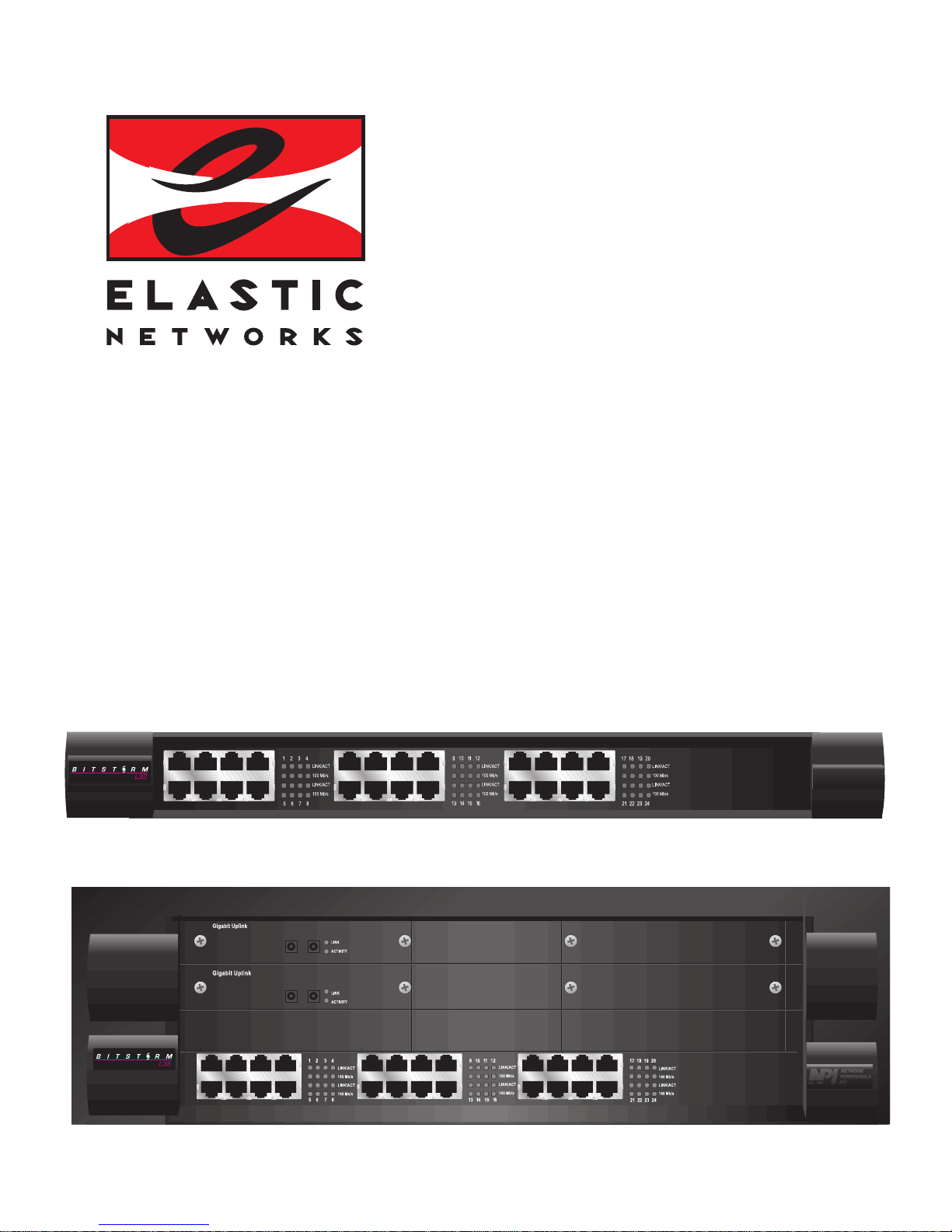
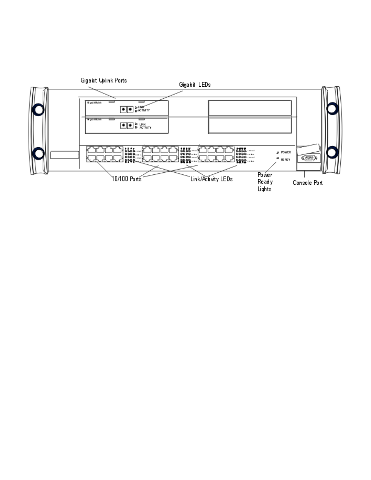
BitStorm L3S-T Overview
The BitStorm L3S-T is a stackable Fast Ethernet Switch with 24 10/100Base-TX ports, two optional Gigabit
uplinks and WAN interfaces.
BitStorm L3S-T front panel
Non-blocking 64Gbps switching fabric
With a powerful, non-blocking 64Gbps switching fabric, this Layer 3 switch is specifically designed to meet the
rapidly changing needs of growing companies. This flexible routing Switch is an ideal wiring closet or collapsed
backbone solution for small and medium-sized businesses, and for branch offices or departments of large
enterprises.
Powerful 96-port stack master
The BitStorm L3S-T can stand alone or be a master controlling a three-unit stack with up to 96 Fast Ethernet and
two Gigabit ports.
This Switch can control any combination of up to three of these EN slave switches:
BitStorm L3S-X with 24 fixed 10/100Base-TX ports with RJ-45 connectors●
A unique stacking interface connects a BitStorm L3S-X switch directly to the BitStorm L3S-T's switching fabric
through slots on the back panel shown below. This is a dedicated 8Gbps connection between each slave and the
master and guarantees full wire-speed, non-blocking performance on all ports throughout the stack.
BitStorm L3S-T back panel
Wire-speed routing, VLANs, QoS traffic classes
Wire-speed IP routing, VLANs and Quality of Service (QoS) traffic classes are some of the other advanced
traffic-enhancing capabilities built into the BitStorm L3S-T. Network administrators can configure these options to
eliminate traditional routers and their bottlenecks, set priorities for network traffic and keep bandwidth-intensive
5
Page 6

applications, like video, under control.
Management
The BitStorm L3S-T includes the BitStorm L3S Series Device Manager for complete switch management. With
the BitStorm L3S Series Device Manager, you can easily configure and monitor the Switch through Netscape,
Internet Explorer, a command line interface or a text-based console program. Or, use HP OpenView or any other
SNMP management system.
Complete, fast, easy
The BitStorm L3S-T offers all these benefits in a complete system package. This innovative Switch installs
quickly and provides instant bandwidth relief—while simple management and automatic features reduce your
operating costs.
Automatic switch activities
Discovers the topology of MAC addresses through hardware-based learning
●
Builds route entries based on ARP requests●
Switches all non-IP packets●
Reads the destination MAC address from packets received from local end stations and either forwards
them to a learned destination port or switches them to ports based on VLAN membership
●
Switches all packets at wire speed●
Major Features
64Gbps switching fabric with wire-speed, non-blocking performance
●
Non-blocking dedicated stacking interface that preserves switch ports●
24 fixed, full duplex, auto-sensing, auto-negotiating 10/100Base-TX ports with UTP RJ-45 connectors●
Two optional Gigabit Ethernet uplink modules, each with a single full duplex 1000Base-SX port with SC
connector
●
Three stacking interface slots on the back panel to connect any combination of slave switches, increasing
port count to a maximum of 96 10/100 ports
●
Store and forward architecture with full error-checking—CRC, alignment, runt, dribble and jabber●
Redundant power supply connector●
Console port for management●
Single entity management across all switches in a stack●
Dynamic IP routing using RIP1, RIP2, OSPF●
Support for up to 1,024 user-defined VLANs by protocol type, MAC address or switch port●
802.1Q VLAN tagging to streamline traffic flow●
802.1p traffic classes to prioritize traffic●
CIDR (Classless Internet Domain Routing) and VLSM (Variable Length Subnet Mask) addressing support●
Spanning Tree Protocol (STP)●
BitStorm L3S Series Device Manager management system including a full Command Line interface●
Complete web-based management control using Netscape or Internet Explorer●
RMON and SNMP support●
Field upgradable firmware with TFTP●
Package contents
The following items are included in the BitStorm L3S-T shipping carton:
BitStorm L3S-T Gigabit Ethernet Switch
●
Two mounting handles with socket head screws●
Allen wrench●
One 120v power cord●
One 240v power cord●
6
Page 7

Four Phillips head rack mount screws●
Console cable●
BitStorm L3S-T Quick Start Installation Guide●
BitStorm L3S-T Release Notes●
BitStorm L3S CD with:
-- BitStorm L3S-T software
-- BitStorm L3S-T User’s Guide
-- Java Windows plug-in for browser-based management
-- BitStorm L3S-T Management Information Bases (MIBs)
-- TFTP Suite2000Pro software
●
7
Page 8
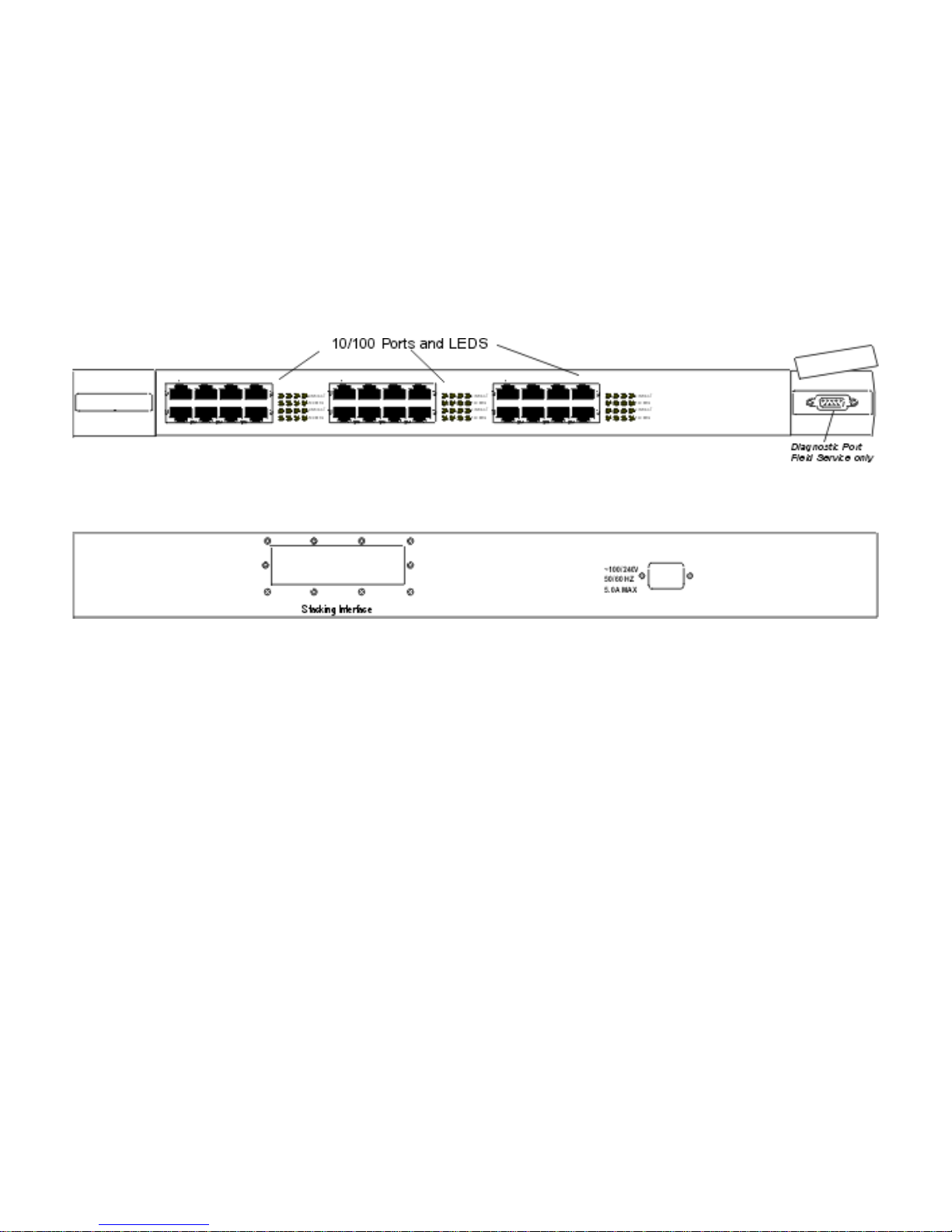
BitStorm L3S-X Overview
The BitStorm L3S-X Gigabit Ethernet Switch is Layer 2/Layer 3 stackable switch with 24 fixed 10/100 ports. This
Switch does not stand alone. It is used only as a slave to the BitStorm L3S-T.
Up to three BitStorm L3S-X switches can be connected to the BitStorm L3S-T stack master using the Stacking
Interface Module shipped with each slave switch.
This Switch has:
24 fixed, full duplex, auto-sensing, auto-negotiating 10/100 Base-TX ports with RJ-45 UTP connectors
●
Built-in stacking interface●
Field service diagnostic port●
BitStorm L3S-X front panel
BitStorm L3S-X back panel
Package contents
The following items are included in the BitStorm L3S-X shipping carton:
BitStorm L3S-X Gigabit Ethernet Switch
●
Two mounting handles with socket head screws●
One 120v power cord●
One 240v power cord●
BitStorm L3S-T Stacking Interface Module and cable●
BitStorm L3S-X Quick Start Installation Guide●
BitStorm L3S-X Release Notes●
BitStorm L3S CD with BitStorm L3S-X software●
8
Page 9
Stacking BitStorm L3S Switches
As new networks are deployed and existing ones continue to grow aggressively, managers need cost-effective
products that can adapt.
Low cost, high-performance “stacked” switches that can be managed as a single entity
are the most desirable solutions, especially for small to medium-sized enterprises.
What is a “stackable” switch?
A stackable solution ensures that a “master” switch can be connected to one or more “slave” switches and that all
can function or be managed as a single logical device.
Built in a predominately standalone fixed-port configuration, this type of switch is typically a single-board system
that is self-contained in an enclosure with its own power supply.
Port density is increased by connecting one switch to another, unlike a chassis-based system in which ports are
added using expansion boards. A stackable switch is connected in a peer-to-peer or in a master-slave relationship
to switches of equal or similar size.
When a “stack” is not a stack
Many manufacturers today say their switches are “stackable” simply because they can be connected using a
single Gigabit uplink on each switch.
This not only “burns” switch resources by stealing a Gigabit link, it is an ineffective design that creates severe
blocking and packet loss between switches. Others use a “virtual chassis” where a separate switch is used as a
“traffic cop” to interconnect switches, again, using gigabit ports for this connection and creating both non
wire-speed transfers and blocking.
These switches are more accurately described as “linked” not “stacked”. They cannot truly be called stackable
switches because:
these external Gigabit links introduce a significant degree of blocking
●
these connections consume switch ports●
in many cases, they are not necessarily managed as a single unit and therefore cannot truly be called
stackable switches.
●
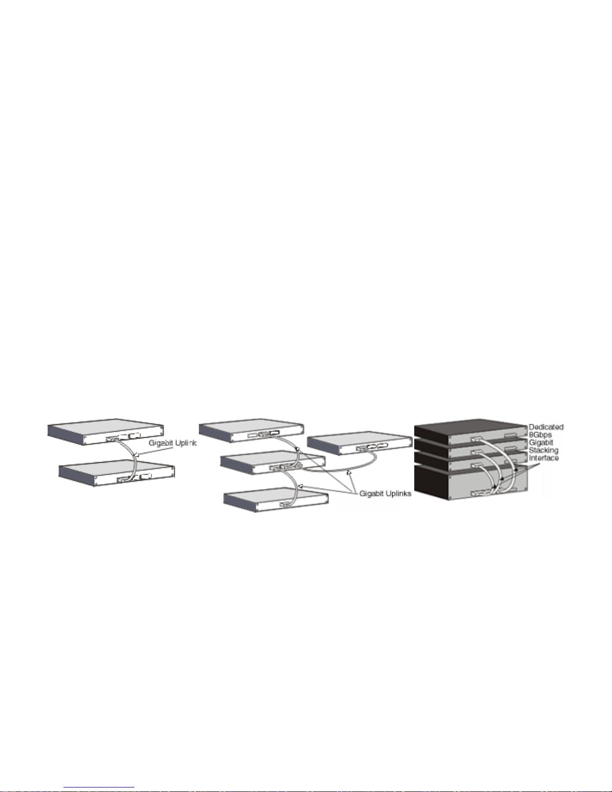
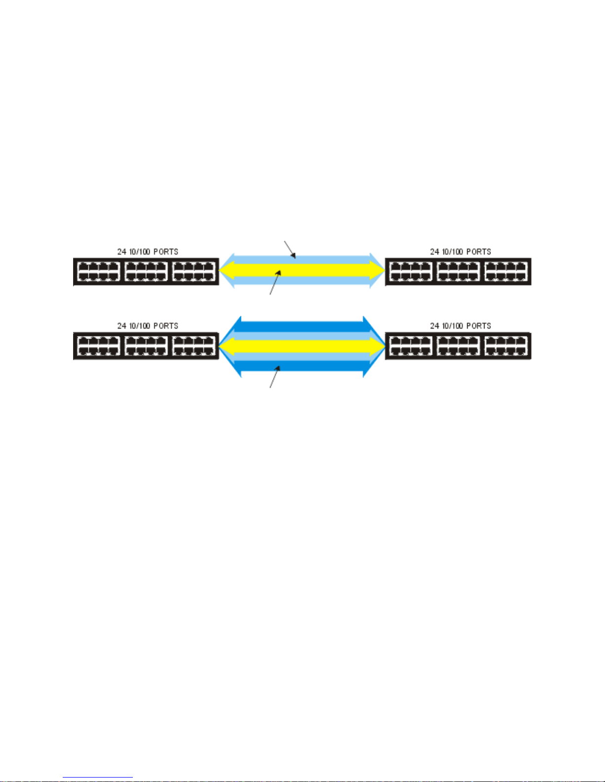
Linking
Some manufacturers “stack” their switches
by using a Gigabit uplink on each switch.
This uses valuable resources and creates
severe blocking and packet loss.
Virtual Chassis
Other manufacturers use a “virtual chassis” concept that burns
Gigabit ports while creating non wire-speed transfers and
blocking constraints.
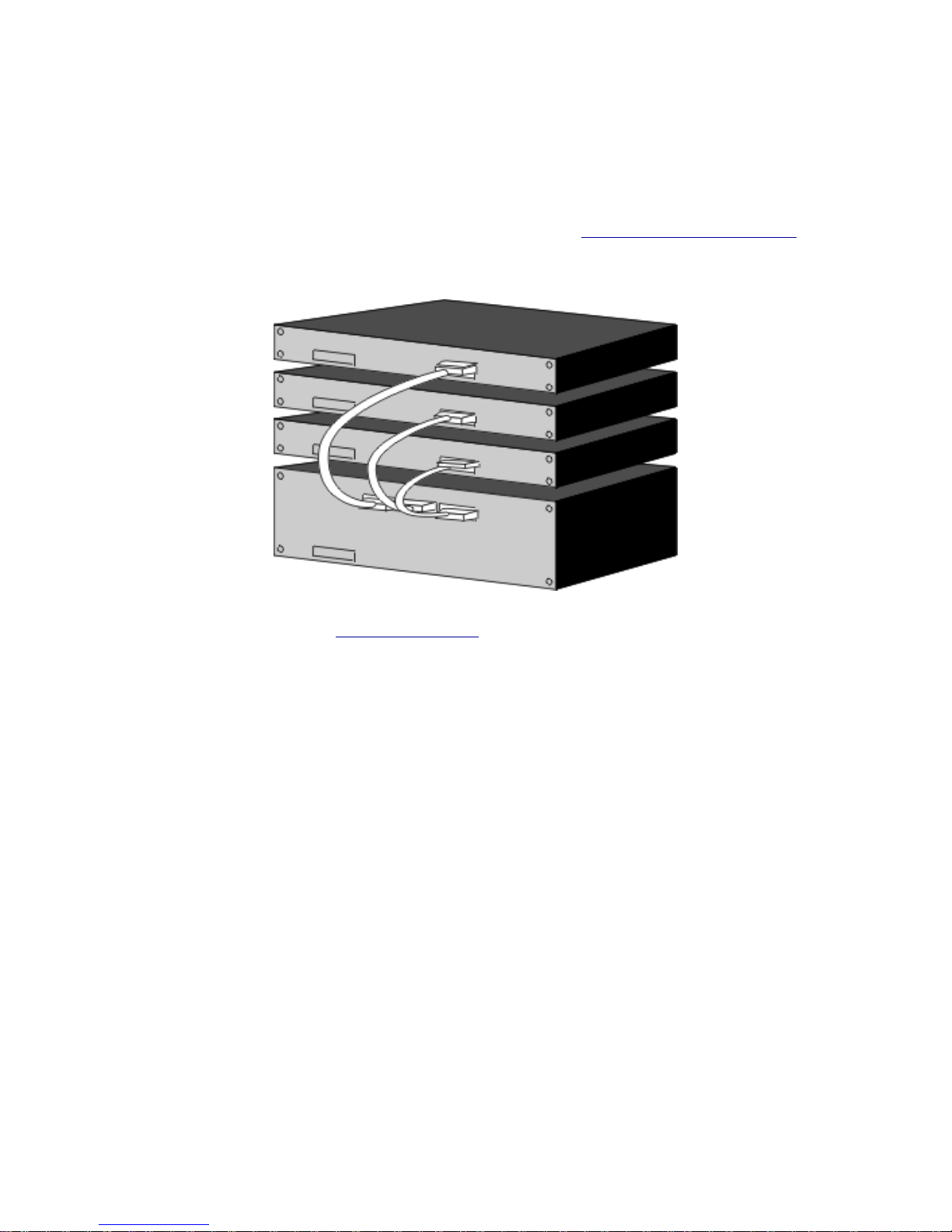
Stacking
The BitStorm L3S system uses dedicated 8
Gbps stacking interfaces to guarantee
wire-speed, non-blocking performance.
When a stack is a stack
The only true stacking interface is a design that uses an external, high-speed bus to interconnect separate
stackable switches.
High-speed stacking bus
This interface connects the ports on the stackable “slave” switches directly to the switching fabric on the “master”
switch. This is the only switch interface technology that can deliver the bandwidth necessary for wire-speed packet
forwarding and eliminate blocking between connected switches.
What is blocking?
Basically, blocking is the inability of a switch to forward traffic due to bandwidth limitations. Technically, packet
transfers are blocked when sufficient bandwidth is not available for all packets to be forwarded at the highest
speed possible on the link.
Packets can be blocked externally as they are forwarded between switches as well as internally within the switch.
Internal, or head-of-line blocking, is eliminated through complex buffering and queuing, while blocking between
9
Page 10
switches is a simple matter of providing sufficient bandwidth for wire-speed packet transfers.
How BitStorm L3S stacking eliminates blocking
BitStorm L3S's high performance stacking architecture guarantees that packets are forwarded at wire speed to all
ports on all switches in the stack without blocking any transmissions. BitStorm L3S does this using a dedicated
high-speed interface connecting all ports directly to the central switching fabric.
Blocking between switches
To avoid blocking between switches, a stackable switch must be able to forward the full traffic load from any of its
switch ports to any switch port on any switch in its stack.
Using the example of a single Gigabit uplink that is used to connect two switches with 24 Fast Ethernet ports, that
single Gigabit uplink is less than half the bandwidth needed to prevent blocking between two switches.
At full duplex, that single uplink delivers only 2Gbps of bandwidth instead the 4.8Gbps needed to forward packets
at wire-speed over all 24 Fast Ethernet ports also operating at full duplex.
At full duplex, 24 Fast Ethernet ports talking to 24 Fast Ethernet ports need 200 Mbps x 24,
or 4.8 Gbps of bandwidth for non-blocking performance.
At full duplex, a single Gigabit link between switches only provides 2 Gbps of bandwidth,
less than half of what's required.
BitStorm L3S stacking dedicates 8Gbps of bandwidth between 24-port switches,
almost double the 4.8 Gbps required for non-blocking transfers.
Single entity management
In a BitStorm L3S stack, the management software running in the master extends its power over the ports on the
slave switches. In effect, the slaves rely upon the greater power of the master. As such, slaves are very cost
effective. The master CPU runs a single management system that sees all ports in the stack as its own, making
the slave switches transparent to the network.
10
Page 11
Routing
This Layer Three Gigabit Ethernet Switch is both a switch and a router.
It operates at Layer 2 like traditional switches, forwarding and discarding packets based only on Media Access
Control layer (MAC) addresses.
Like traditional routers, it also operates at Layer 3, using network layer
information to route packets to another router, switched network segment or end-station.
Wire-speed routing
But, unlike traditional routers, the Switch routes at wire-speed, nearly ten times faster than conventional routers.
Conventional routers maintain routing tables in software and use a CPU to look up and maintain these
addresses. This Switch achieves routing at wire speed by using Application Specific Integrated Circuits, or
ASICs, to maintain routing tables in hardware.
The Switch eliminates the need for routers in the local area network (LAN). It might also be called a high-speed
or hardware-based router.
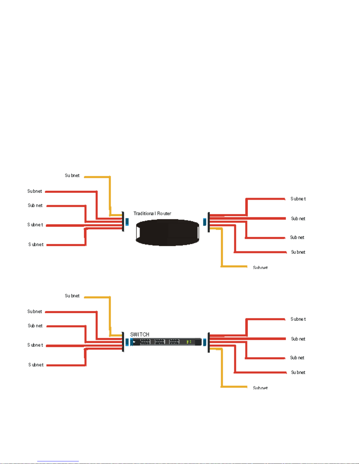
Migrating from routing to multi-layer switching
Migrating from a router-centric network to a BitStorm L3S network is extremely simple.
A typical, traditional collapsed backbone layout in a small company places the router in the center of the network
to create IP subnets and stop broadcast traffic from flooding the entire network.
That router can be replaced by a BitStorm L3S Layer 3 Gigabit Ethernet switch and moved to the edge of the
LAN to handle WAN communications.
Layer 2 switches can now be moved into workgroups, replacing hubs and putting each user on a dedicated port.
As traffic demands increase, those Layer 2 switches can be replaced by more BitStorm L3S switches.
How the Switch handle IP routing
On a local network, a Layer 2 switch identifies and transfers packets by reading the hardware addresses—the
source and destination MAC addresses. A Layer 2 switch cannot forward traffic destined outside of its local
11
Page 12

network, so a router would be attached to one of the Switch’s ports and the router is set as the Switch’s default
gateway.
The Layer 2 switch propagates all packets to be routed to the router. The router compares the IP destination
address in each packet it receives to the information in its routing table, then either drops the packet or forwards
it to another router or network segment.
Dedicated routers are expensive, complex and slow.
They can create serious network bottlenecks because they must analyze all broadcast packets, forwarding
some, while maintaining up to date routing tables by communicating with other routers.
Traditionally, this processing is handled by the CPU and can be extremely time-consuming.
This Switch does the work of both of these devices, switching packets locally using Layer 2 information, building
and maintaining routing tables and routing packets like a traditional router, but at wire speed. The Switch
achieves wire-speed routing because IP address information is cached in hardware. The Switch does not have to
rely on its CPU for processing.
Enabling routing
Routing on this Switch is not only much faster, it is much easier to configure than on a traditional router. The
network manager configures routing interfaces by creating one or more port-based VLANs and by assigning an
IP address and subnet mask to the VLAN.
Dynamic routing protocols
These switches can also be configured to use standard routing protocols—RIP1, RIP2, OSPF—to calculate
paths through the network. They can be deployed on any network regardless of routing protocols already in use.
For more details, see:
Routing Information Protocol (RIP)●
Open Shortest Path First (OSPF)●
12
Page 13

The Routing Information Protocol (RIP)
The Routing Information Protocol (RIP) is an Interior Gateway Protocol (IGP) used mainly on
moderately-sized networks. RIP uses a vector-distance routing method that keeps a table of all known IP
address destinations (the vector) and the number of hops to reach them (the distance).
Configuring RIP
To configure RIP settings using either the Command Line or Web version of the BitStorm L3S Series Device
Manager, see:
Configuring RIP - Command Line version●
Configuring RIP - Web version●
For an overview of RIP and the settings you need to make in configuring RIP, see Background below. For
complete details, refer to RFC 1058 and RFC 1723, which define RIP versions 1 and 2.
Background
RIP routers choose the network path that goes through the minimum number of routers, or hops. RIP supports a
maximum hop count of 15. Destinations 16 hops or more away are considered unreachable.
The hop count is also referred to as the cost or metric. IP address prefixes belonging to directly connected
network segments appear in the routing table with a cost of 1.
RIP routers exchange routing information with other RIP routers by broadcasting updates at regular, pre-set
intervals. These updates include a copy of a router's entire routing table, the list of all known destination prefixes
and their metrics.
When it receives a RIP update from a neighbor, a RIP router decides whether or not to update its own routing
table.
Triggered updates
When its routing table does change, the RIP router can be set to broadcast updates immediately without waiting
for the preset update timer whose default is 30 seconds. These are called triggered updates. Triggered updates
advertise only those prefixes whose cost has changed. For example:
an interface has been enabled
●
an interface has gone down●
a RIP update from a neighbor has modified the routing table●
a routing table entry has timed out●
Because a RIP router expects to receive routing updates continually, it eventually gives up on the next-hop
router after it fails to receive updates. After 90 seconds pass without an update from the next hop router, the
router moves the next hop to any neighboring router that advertises a path of equal cost. After 180 seconds, the
entry is declared unreachable.
RIP can be enabled on any routing interface on your Switch. When you configure RIP, the Switch uses this
protocol to determine the best path to another network. It does this by sending and receiving updated routing
information from other RIP routers.
It compiles this information in a routing table of every network destination it has learned. This table includes:
the IP address of the destination network
●
the metric, or number of hops, to the destination network●
the IP address of the next router●
a timer indicating how much time has elapsed since an entry was last updated●
Under RIP, routers are either active or silent. Active routers advertise their routes to others. Silent routers can
only listen. They cannot send routing information to others. Both active and silent RIP routers listen to all
messages and update their routing tables accordingly.
Once a RIP-enabled routing interface learns a route, it keeps it until it learns a better one. If the first port to
advertise a route fails, all listeners must timeout all routes they learned via RIP from all other RIP ports. A route
13
Page 14

becomes invalid if 180 seconds pass without that route being advertised again.
RIP has certain features that provide stability in rapidly changing network conditions.
Split horizon
When RIP enabled interfaces are initialized, they build a routing table based on their directly connected
interfaces. During the time it takes for this information to converge and the best route to be determined and
stabilized, routing loops can occur. These loops are created when one routing interface receives information that
includes itself as an intermediate hop to another destination.
For example,
Router Interface 2 has a route to Router A, broadcasts that to Router Interface 1, which broadcasts
back to Router Interface 2 a route to A, with Router Interface 2 as an intermediate hop.
Split horizon helps reduce bandwidth consumption and speeds up information distribution by advertising to an
interface only the routing information obtained from other interfaces. Router Interface 1 does not advertise the
routes it learned from Router Interface 2 back to Router Interface 2.
Poison reverse updates
Poison reverse updates prevent larger loops in a network by setting the metric (cost) of neighboring routers to
infinity, and therefore, unreachable.
14
Page 15
Open Shortest Path First (OSPF)
Open Shortest Path First (OSPF) is an Interior Gateway Protocol (IGP) developed to overcome some of RIP's
limitations when it operates in more complex networks.
Where RIP keeps a table of all known destinations and the number of hops to reach them, OSPF is a link-state
routing method that keeps routing information only for the router's IP domain and its neighboring routers, not the
entire network.
OSPF works best in hierarchical networks, while RIP, which is a simpler protocol to manage, works best in flat
networks.
For complete technical details on implementing OSPF, refer to RFCs 1583 and 1850 which define
OSPFv2.
OSPF benefits
faster route convergence
●
conserves bandwidth, only sending updates when changes occur●
no hop count limit●
supports hierarchical topologies●
OSPF overview
OSPF splits the network into independent parts called areas and connects these areas to a backbone area.
Each area is identified with a unique 32-bit area_id number imbedded in OSPF packets. The Switch processes
OSPF packets only if one of its interfaces resides in the area advertised by the packet.
Each OSPF router builds a shortest path tree with itself as the root. The router sends updates to its neighboring
routers and verifies that they all have a consistent network map.
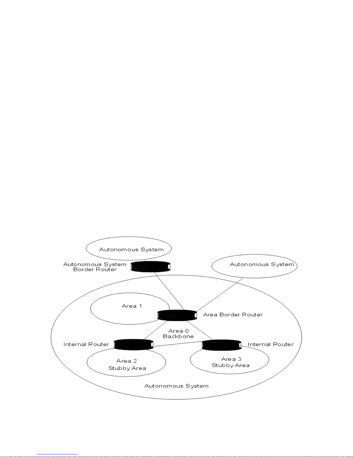
Autonomous system
In OSPF, a single IP domain is called an autonomous system (AS). The topology within other areas is hidden
from the rest of the autonomous system.
This diagram illustrates the OSPF areas and types of routers described below.
Area 0 - the Backbone
An OSPF network must have an area configured as Area 0, or the backbone area. All areas in an
●
15
Page 16

autonomous system must be connected to the backbone. This backbone area allows summary
information to be exchanged between Area Border Routers. When designing an OSPF network, you
should start with Area 0.
Stub Areas
A stub area is an area that is only connected to one area, often this is the backbone area. Route
information is not advertised into stub areas. By creating stub areas, you reduce the router's memory use
and processing requirements.
●
Not-so-Stubby Areas (NSSA)
A not-so-stubby area is the same as a stub area except that external routes learned by an Autonomous
System Border Router can be advertised within the NSSA. Likewise, external routes learned in an NSSA
can be advertised to other areas.
●
OSPF routers
OSPF classifies different types of routers depending on the area in which they reside and what their tasks are.
An Internal Router (IR) is one with all of its routing interfaces in the same OSPF area.
●
An Area Border Router (ABR) has interfaces in more than one OSPF area. Every ABR listens and
exchanges information with other ABRs. By examining the advertisements from other ABRs, an ABR
creates its link state database
●
An Autonomous System Border Router (ASBR) is a gateway between OSPF and other routing
protocols or other autonomous systems.
●
Link State Database
A Link State Database is used to create the OSPF routing table. This database contains all the Link State
Announcements (LSA) that it has issued and received. All routers within an area have exactly the same Link
State Database.
Link State Announcements (LSA)
When OSPF is configured on a routing interface on a BitStorm L3S Switch, the Switch sends a Link State
Advertisement (LSA) over the routing interface. This LSA tells neighboring routers the state of the routing
information in that routing interface's Link State Database.
Configuring OSPF
To configure OSPF, see:
OSPF Configuration Basics●
16
Page 17

Virtual LANs
A virtual LAN (VLAN) is a logical way to segment a network without changing physical connections. In a VLAN,
broadcast packets or packets with unknown destination addresses are forwarded only to ports that are VLAN
members.
Eliminate need for more routers
Using VLANs, you can increase network segmentation without adding more hardware. VLANs can eliminate the
need for existing routers or for more routers as your network grows. Existing routers can be redeployed to
concentrate on WAN traffic. Think of VLANs as simply a group of end-stations that
can be on multiple physical segments,
●
are not constrained by their physical location,●
can communicate as if they were on a common LAN.●
Major VLAN benefits
Reduces the size of the collision domain and load on servers and workstations by filtering out irrelevant
traffic
●
Eliminates complicated, time-consuming move and change procedures as users change workgroups●
Reduces traffic over routers●
Increases security●
Simple management for more than 4,000 VLANs
Your Switch can support up to 4,096 VLANs and has features that reduce complex VLAN configuration and
management.
Layer 2 VLANs
You can create Layer 2 VLANs based on ports on the Switch or end-station MAC addresses. Port-based VLANs
create immediate and separate collision domains on a single switch or directly-connected switches. MAC
address-based VLANs could be used in environments where laptop users want to connect to the network on any
available network jack.
Layer 3 VLANs
You can create Layer 3 VLANs manually or let the Switch create them automatically. The Switch can currently be
set to automatically create network protocol-based VLANs.
802.1Q VLAN tagging
The Switch supports 802.1Q VLAN tagging, a process whereby the Switch dynamically inserts VLAN
membership information into packets to distribute VLAN membership information across multiple switches.
This VLAN membership information comes from
the administrator configuring specific VLANs
●
the Switch learning VLAN identity by snooping the packets traveling through it●
VLAN-tagged packets are forwarded within the Switch only to ports leading to a VLAN member and outside of
the Switch to other 802.1Q compliant switches.
802.1Q VLAN tagging—externally
The IEEE 802.1Q VLAN tagging standard defined how manufacturers could create devices that would support
VLANs that could span multiple switches from different vendors. This interoperability and traffic containment
across different switches is the result of a switch's ability to use and recognize the 802.1Q Tag Header
.
Switches that implement 802.1Q tagging add this tag header to the frame directly after the destination and
source MAC addresses. Your Switch supports external 802.1Q VLAN tagging, fully described in VLAN Tagging.
802.1Q VLAN tagging—internally
Just as importantly, the adoption of this standard also gave EN a mechanism to streamline traffic within the
Switch itself.
Your Switch, automatically and transparently, makes filtering and forwarding decisions by reading
VLAN membership information contained in the packet header and updating VLAN membership tables by what it
learns. This is how it works:
17
Page 18

Incoming
The Switch classifies packets coming in on a port based on their VLAN identifier (VID)—or lack of one. If
the packet has a VID, the Switch forwards the packet only to the ports for that VLAN.
●
VLAN tagging
If the packet does not have a VID, the Switch assigns one based on what it has learned. It inspects the
packet and places it in a VLAN based on what it learns. It assigns the packet to an existing VLAN in the
following order.
IP address
❍
network protocol type❍
MAC address❍
If there are no matches, the Switch tags the packet with the VID of the port it came in on.❍
●
Learning
The Switch learns VLAN membership information by inspecting the source addresses and VLAN
classification of all incoming and outgoing packets and records this information in its forwarding database.
●
Filtering and forwarding
Based on the information found in the VLAN database and the port state, the Switch either forwards
packets to other ports or filters them.
●
To learn how to use and configure VLANs, see:
Sample VLAN Applications●
Configuring VLANs—Overview●
18
Page 19

Sample VLAN Applications
Here are some examples of how different types of VLANs solve business and network traffic dilemmas.
Users in the Engineering Department have highly sensitive material that needs to be protected.●
Solution: Create firewalls by placing each user into his or her own MAC-based VLAN. Traffic to
that VLAN is intended only for that user. No one can listen to that user’s traffic because it never
goes onto any other segment. Or, you can ensure greater security by dedicating a switch port to
each user in their own port-based VLANs, creating both a physical and a virtual restriction.
Users in the Accounting and Manufacturing Departments need guaranteed access to the
mainframe via SNA.
●
Solution: Create a protocol-based VLAN and set a priority level for this traffic using Quality of
Service. These users are members of other VLANs—such as the corporate email VLAN—but their
SNA traffic will always be handled as the Switch’s first priority traffic.
The Sales Department has mobile, laptop users who need to dial in and often work from different
company branch locations.
●
Solution: Create an IP subnet VLAN using IP addresses to identify each user. Regardless of
where they are on the corporate network, or which docking station or network jack they use, they
will be located.
The company’s top executives—the President and Vice Presidents of all departments—need
access to the Accounting, Sales and Manufacturing VLANs.
●
Solution: Make each executive a member of each departmental VLAN.
A member of the Accounting VLAN sits in the Sales Department, using the Sales Department
printer. Each time he prints, the print job travels over the router to the printer.
●
Solution: Make the printer a member of both the Sales VLAN and the Accounting VLAN.
19
Page 20

Management Options
The Switch is shipped complete with its own SNMP management system called the BitStorm L3S Series Device
Manager. This management system gives you different levels of control over all of the Switch's functions through
three different user interfaces:
a command line
●
a text-based console●
a web browser●
The management capabilities vary depending on your selection. For complete details, see these sections:
The BitStorm L3S Series Device Manager - Command Line version●
The BitStorm L3S Series Device Manager - Console version●
The BitStorm L3S Series Device Manager - Web version●
You can also manage the Switch using:
HP OpenView or any other SNMP-based management software
●
Telnet●
In-band and out-of-band management
You can manage your Switch either in-band or out-of-band.
Out-of-band
Directly at the Switch, using the console version of the Switch's built-in BitStorm L3S Series Device
Manager. You can access this text-based software using a VT100 terminal or workstation running
VT100 emulation software, such as Windows HyperTerminal, connected to the Switch's console
port.
❍
Directly at the Switch, using an SNMP-based network management system installed on a
workstation directly connected to the Switch's console port.
❍
Remotely through a modem attached to the Switch's console port, using the Switch's built-in
console program or any SNMP-based network management system
❍
●
In-band
Over the network, using an SNMP-based network management system installed on a network
workstation or Telnet.
❍
●
20
Page 21

Installing the BitStorm L3S-T Switch
Selecting a Proper Location●
Cabling Guidelines●
Installing the Gigabit Uplinks●
Building a Stack●
Installing the Stacking Interface●
Mounting in an Equipment Rack●
Powering On the Switch●
Setting Up the BitStorm L3S-T Management Console●
Setting the IP Address, Mask and Gateway●
Installing TFTP Suite2000Pro●
Upgrading Firmware●
Finishing the Installation●
System Password●
21
Page 22

Selecting a Proper Location
The Switch can be located in a wiring closet or equipment room, either mounted in a standard 19-inch equipment
rack or left free-standing.
In selecting a location, make sure that:
you follow the proper cabling guidelines●
the Switch is accessible and cables can be connected easily●
cables are away from sources of electrical noise such as radios, transmitters, broadband amplifiers, power
lines and fluorescent lighting fixtures
●
water or moisture cannot enter the case of the unit●
airflow around the unit and through the vents on the side of the case is not restricted. A minimum of 25mm
or 1 inch clearance on all sides is recommended.
●
no objects are placed on top of the unit.●
22
Page 23

Cabling Guidelines
Switches can be cabled together through any port following the maximum IEEE standard cabling
distances outlined below.
●
When connecting a switch to another switch or hub, use a crossover cable.●
All Fast Ethernet ports can be connected to workstations, hubs, servers or other switches. To operate at
100Mbps, workstations and servers must have a Fast Ethernet Network Interface Card (NIC) installed.
●
Likewise, any device connected to a Gigabit port requires a Gigabit NIC to be able to run at 1000Mbps.●
Make sure you conform to all local electrical and safety standards.●
Cable Distances
Standard
Media Type
Mhz/Km
Rating
Maximum Distance
1000Base-SX 50/125 um Multimode Fiber 400 500 meters
50/125 um Multimode Fiber 500 500 meters
62.5/125 um Multimode Fiber 160 220 meters
62.5/125 um Multimode Fiber 200 275 meters
1000Base-LX 50/125 um Multimode Fiber 400 550 meters
50/125 um Multimode Fiber 500 550 meters
62.5/125 um Multimode Fiber 500 550 meters
10um Single-mode Fiber N/A 5,000 meters
10/100Base-TX
Category 5 UTP Cable (100Mbps)
100 meters
10Base-T
Category 3 UTP Cable (100Mbps)
100 meters
23
Page 24
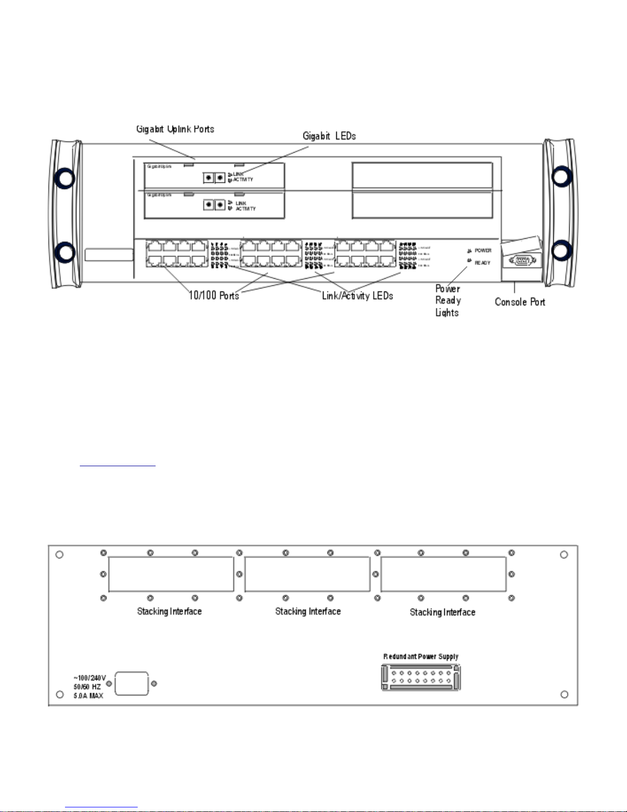
Installing the Gigabit Uplinks
The BitStorm L3S-T has two optional Gigabit uplink modules. The slots for both of these modules are located on
the Switch's front panel shown here:
Installation steps
Unplug the Switch.
●
Remove the blank plate covering the expansion slot by gently inserting the tip of a small, flathead
screwdriver under the plate. Pop off the plate and discard.
●
Slide the expansion module into its slot until it is firmly seated.●
Attach network cables.●
Power on the Switch.●
Check the LEDs on the module to make sure the module is properly installed. If the Link lights are green,
the module is working properly. If an Activity light on the Gigabit module is yellow, the port is operating at
1000Mbps.
●
24
Page 25
Building a Stack
The BitStorm L3S-T can stand alone or be a master controlling of stack of up to three L3S-X switches.
When an EN switch is installed in a stack, you configure all ports on the L3S-X switches using the BitStorm L3S
Series Device Manager on the BitStorm L3S-T.
Basic steps
Install the Stacking Interface Module in the BitStorm L3S-T. See Installing a Stacking Interface.●
Connect the slave switch to the BitStorm L3S-T using the Stacking Interface Cable shipped with the
module as shown here:
●
Connect the correct power cable for your locale to the slave switch and plug it into an electrical outlet.●
Rack mount all switches. See Mounting in a Rack.●
Configure and manage all ports on all stacked switches following the instructions for the BitStorm L3S-T.●
25
Page 26
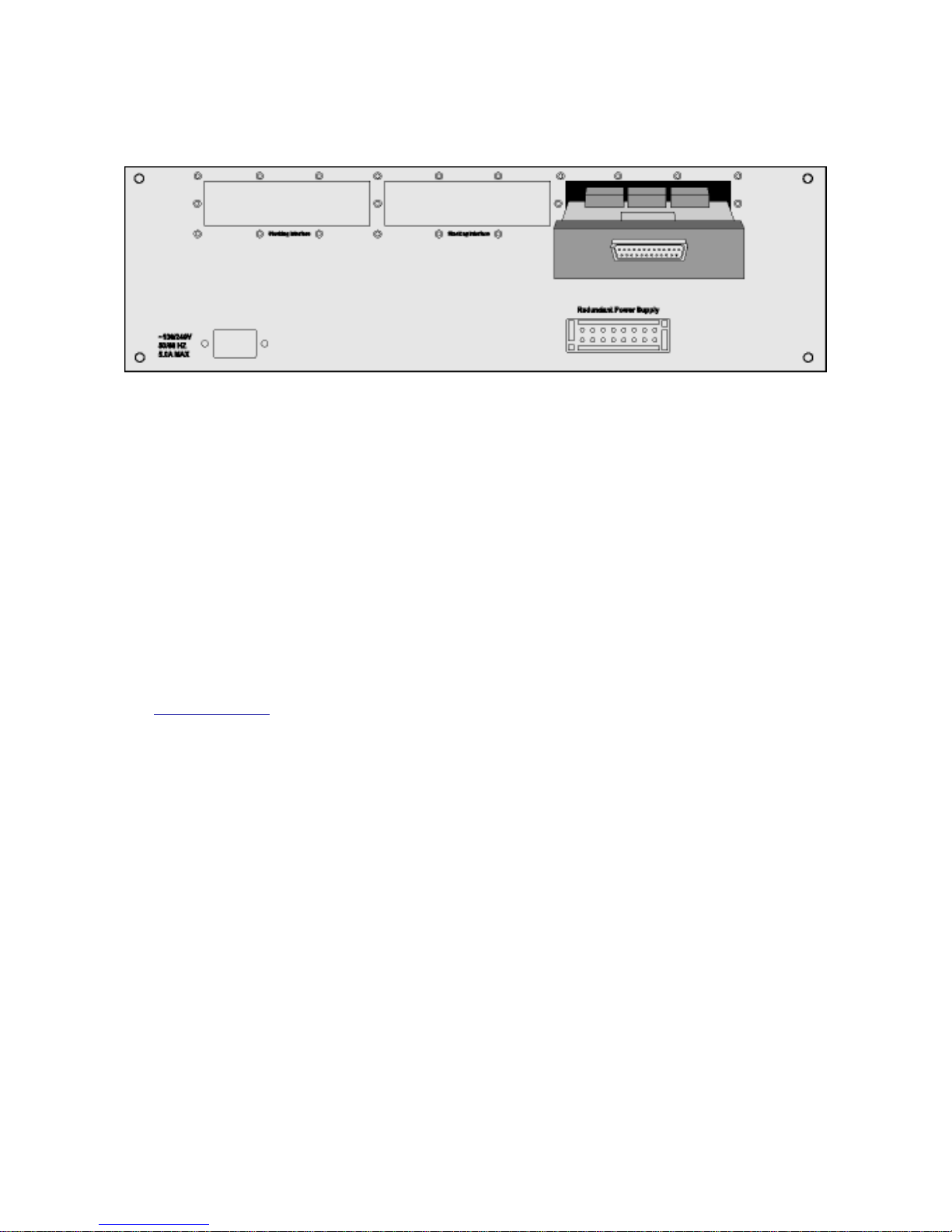
Installing a Stacking Interface
The BitStorm L3S-T has three stacking interface slots to connect any BitStorm L3S-X slave switches. These
slots are located on the Switch's rear panel shown here:
Installation steps
Power down the BitStorm L3S-T stack master and any existing BitStorm L3S-X switches connected to it.
1.
Unplug the BitStorm L3S-T's power cable.2.
Place the BitStorm L3S-T right side up on a hard, flat surface with the rear facing you.3.
Locate the three stacking interface slots on the rear panel.
Important:
Always populate slots from right to left. When the stack is powered on, the management software assigns
port numbers starting with the ports connected in the right slot, then the middle and finally, the left.
4.
Unscrew the blank metal plate covering the slot.5.
Remove the blank plate and discard.6.
Slide the Stacking Interface Module into the slot, making sure it is firmly seated.7.
Repeat these steps for each stacking interface you are installing.8.
Attach the BitStorm L3S-X switches to the BitStorm L3S-T following instructions for building a stack.9.
See Building a Stack●
26
Page 27
Mounting in an Equipment Rack
The BitStorm L3S-T Switch and its slaves, the BitStorm L3S-X, fit in most standard 19-inch equipment racks. All
come with hardware that must be attached before mounting.
Important safety instructions
Maximum operating temperature is 40 degrees Celsius.
●
Never restrict the airflow through the device's fans or air vents.●
When installing equipment into a rack, distribute the units evenly. Otherwise, hazardous conditions may
be created by an uneven weight distribution.
●
Connect the unit to a properly rated supply circuit.●
Reliable earthing (grounding) of rack-mounted equipment should be maintained.●
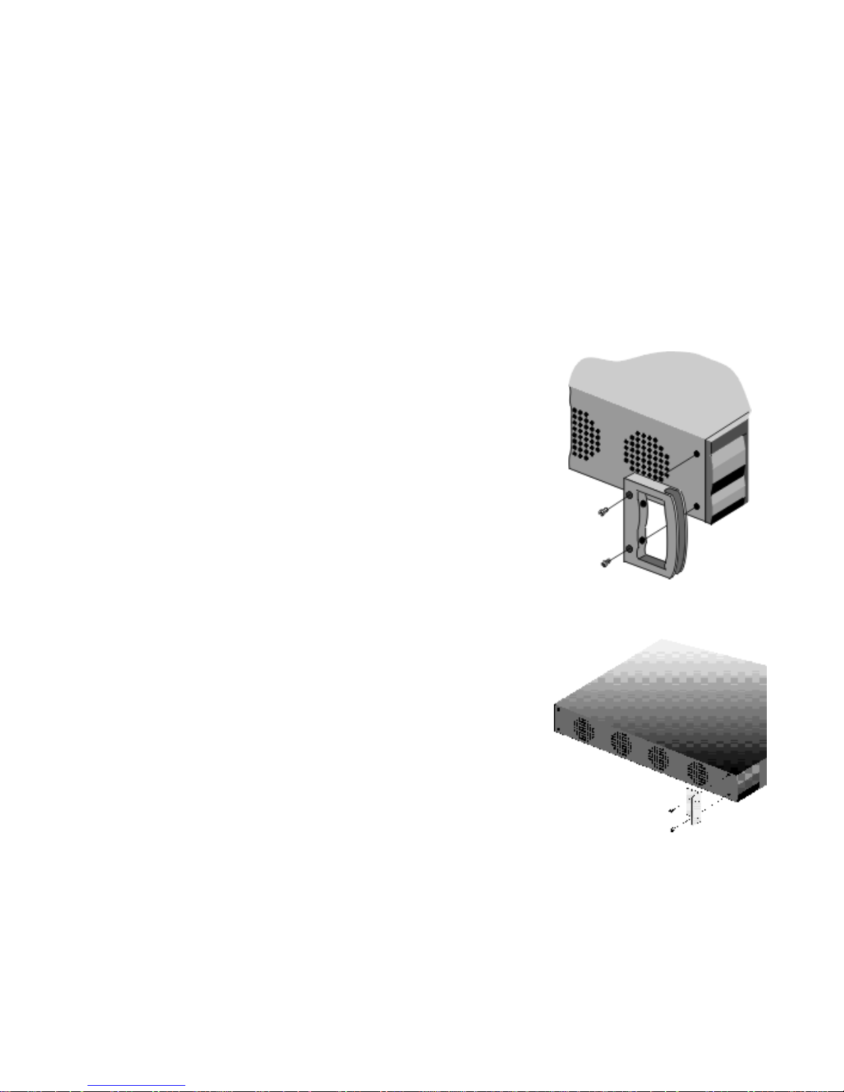
BitStorm L3S-T
The BitStorm L3S-T comes with mounting handles, socket head screws and an Allen wrench. To attach these
handles:
Place the unit right side up on a hard, flat surface with the front facing
you.
●
Locate a handle over the mounting holes on one side of the unit as
shown.
●
Insert the socket head screws and tighten with the supplied Allen
wrench.
●
Repeat the two previous steps for the other side of the unit.●
Insert the unit into a 19-inch rack making sure that the ventilation holes
are not obstructed.
●
Secure the unit in the rack using the rack mount screws provided and a
Phillips head screwdriver.
●
BitStorm L3S-X
The BitStorm L3S-X comes with mounting brackets and Phillips head screws. To attach these handles:
Place the unit right side up on a hard, flat surface with the front
facing you.
●
Locate a bracket over the mounting holes on one side of the unit as
shown.
●
Insert the screws and tighten fully.●
Repeat the two previous steps for the other side of the unit.●
Insert the unit into a 19-inch rack, making sure that the ventilation
holes are not obstructed.
●
Secure the unit in the rack (screws not provided).●
27
Page 28

Powering On the Switch
Testing the Switch
Test the Switch by turning it on before connecting it to the network.
Select the correct power cable
Two types of power cables are shipped with the Switch to accommodate the
world's different electrical systems. Select the cord for your locale and plug it
into the power outlet on the Switch's rear panel.
System LEDs
The LEDs on the Switch’s front panel will light and blink as the Switch runs
its power on self-test (POST). When the Ready light is green and blinking,
the POST test is completed successfully. If this does not happen, contact
your supplier or EN Technical Support.
Checking system status
If network cables are connected, be sure that the Switch is operating correctly by comparing the color of the
LEDs to this chart:
System LEDs
Color Indicates
Power Green Switch is turned on
Ready Blinking Green Switch is operating properly
10/100 LEDs
Link/Activity Green Port is connected
Blinking Green Port is handling traffic
100 Mp/s Yellow not on Port is operating at 10 Mbps
Yellow on Port is operating at 100 Mbps
Gigabit LEDs
Link Green Port is connected
Activity Yellow Port is operating at 1000 Mbps
28
Page 29

Setting Up the BitStorm L3S-T Management Console
You must connect a management console to the BitStorm L3S-T to change its IP address, subnet mask and
default gateway. If this Switch is also a stack master, this IP address information applies to the entire stack.
These settings are made using the BitStorm L3S-T's built-in BitStorm L3S Series Device Manager. You reach
this software through a PC or terminal attached to the console port on the front of the BitStorm L3S-T Switch.
Attaching a console to the BitStorm L3S-T
Your management console can be a PC or terminal running VT100 terminal
emulation software, such as Windows Hyperlink.
●
Remove the rubber EN name plate covering the console port on the BitStorm
L3S-T's front panel.
●
Using the serial cable shipped with the unit, or your own null modem cable,
attach the management console to this port.
Important: Make sure you attach the management console to the BitStorm
L3S-T, not a slave switch. The BitStorm L3S-X console ports are for field
diagnostic purposes only.
●
Set the terminal to:●
Baud - 19200
Parity - None
Data Bits - 8
Stop Bit - 1
Flow Control - None
After installation:
Once the Switch is successfully installed on your network, you can manage it out-of-band directly at the console
port, over a modem, or in-band from any management station on the network.
You can use either the Console or Web version of the BitStorm L3S Series Device Manager, both of which are
built into the Switch, or any SNMP-compliant management system. See Management Options.
29
Page 30
Setting the Switch's IP Address, Mask and Gateway
The Switch is shipped with the these defaults:
IP address
192.168.111.1(255.255.255.0)
Gateway address
192.168.111.2 (255.255.255.0)
Important:
IP information applies to all switches in the stack.
●
The default gateway is used in both Layer 2 and Layer 3 configurations to resolve addresses not handled
by RIP or attached devices. You must change these defaults to the valid IP address for the Switch. If you
don't, the Switch continues to issue ARP requests from the default VLAN every 2 seconds.
●
You can set the Switch to receive its IP address and subnet mask from a DHCP server. The Default
Gateway must be changed manually.
●
To change these default settings, you can either Telnet into the Switch using these default settings, or change
them using a management console. These settings are changed using the Console version of the BitStorm L3S
Series Device Manager, the Switch's built-in management software.
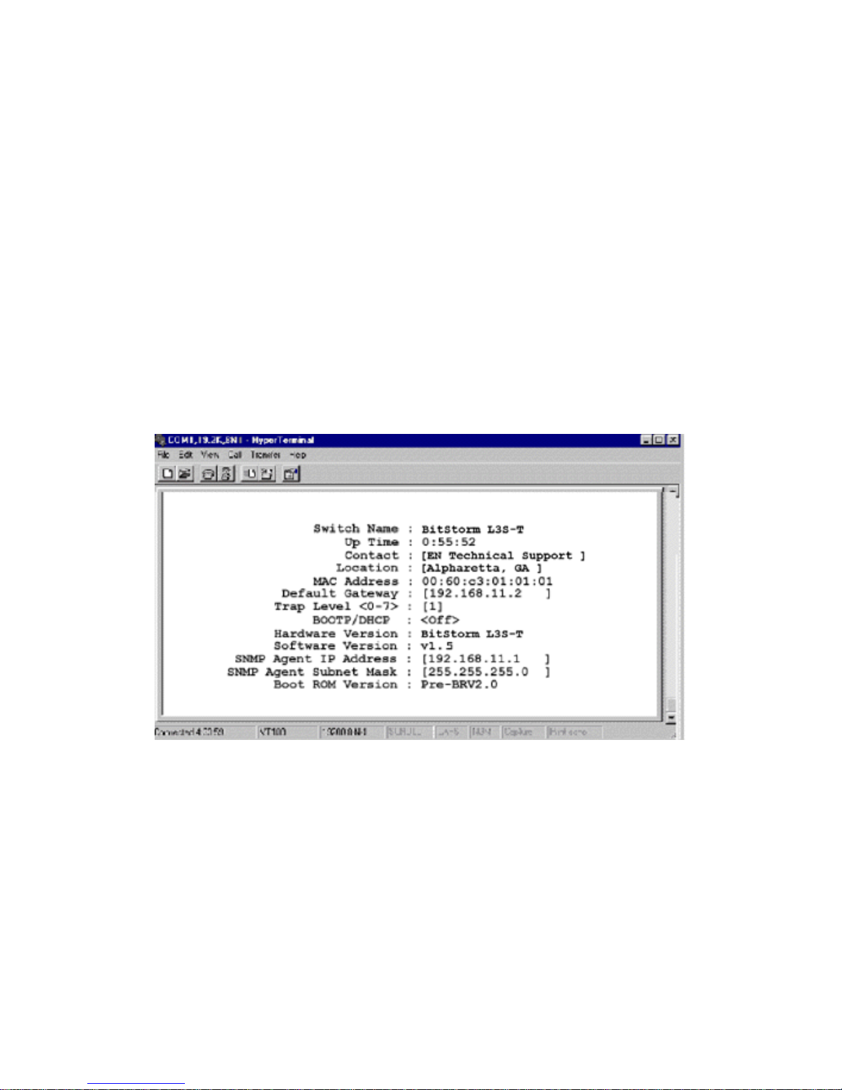
Setting the IP address, subnet Mask and default gateway
Select System Configuration from the BitStorm L3S Series Device Manager Console Main Menu to
display the System Configuration screen shown below.
●
To have the Switch receive its IP address and subnet mask from a DHCP server, select On in the
BOOTP/DHCP field. Depending on your configuration choices, the Switch can use many IP addresses.
The IP address assigned by DHCP applies only to the Switch's default port-based VLAN.
●
If you are not using DHCP, enter the unique IP address of this Switch in the SNMP Agent IP Address
field and the Switch's subnet address in the SNMP Agent Subnet Mask field.
●
Enter the unique IP address of this Switch in the SNMP Agent IP Address field.●
Enter the Switch’s subnet address in the SNMP Agent Subnet Mask field.●
Specify an IP address for a gateway or router in Default Gateway for the management interface.●
Save your settings.●
Reboot the Switch for changes to the IP address and subnet mask to take effect. You do not need to
reboot when changing the Default Gateway.
●
30
Page 31

Installing TFTPSuite2000Pro
TFTPSuite2000Pro is located on the CD shipped with the Switch. This software or any TFTP server software is
required to upgrade the Switch's firmware. TFTPSuite2000Pro software can be loaded on any networked
Windows PC with a CD ROM drive.
Place the BitStorm L3S CD in the computer's
CD drive and install TFTPSuite2000Pro
following the directions that appear on your
screen.
1.
Select the TFTPServer32 icon to launch the
server software.
2.
From the screen that appears, select System,
then Setup as shown here.
3.
From the Setup screen, select Outbound.
Enter the path to the directory where the
firmware update resides as shown in this
example:
4.
Next, select Options. Select Allow tSize
option request. Click on OK to complete the
setup.
5.
Setup
Outbound
Options
31
Page 32

Upgrading Firmware
System software upgrades that add new capabilities to your Switch or stack of Switches are available on our
website as soon as they are released.
Before you begin:
To upgrade firmware for the BitStorm L3S-T :
Go to www.elastic.com and download the latest firmware update file.1.
Place the downloaded file on a TFTP server.2.
If you do not already have a TFTP server, install the TFTPSuite2000Pro TFTP software found on the
BitStorm L3S CD shipped with your Switch. For instructions, see Installing TFTP Suite2000Pro.
3.
Run the TFTP server.4.
From the Switch's management console, go to the Console Main Menu.5.
To upgrade firmware using the Console version, select System Setup.6.
To upgrade firmware using the Command Line version, select Command Line Interface.7.
Follow Upgrading BitStorm L3S-T firmware using the Console Program or Upgrading BitStorm
L3S-T firmware using the Command Line below.
8.
To upgrade firmware on a BitStorm L3S-X:
Make sure that the BitStorm L3S-T and all BitStorm L3S-Xs to be upgraded are fully operational
and properly installed in a stack.
❍
Connect a management console to the BitStorm L3S-T console port. For instructions, see Setting
Up the BitStorm L3S-T Management Console.
❍
Make sure you have downloaded the latest firmware to your TFTP server as described in Steps 1-5
above.
❍
From the Switch's management console, go to the Console Main Menu.❍
Follow the instructions under Upgrading BitStorm L3S-X firmware below.❍
9.
Upgrading BitStorm L3S-T firmware using the Console version
From System Setup, select Firmware Upgrade. This screen appears:
1.
In Host IP, enter the IP address of the TFTP server.2.
In File Name, enter the name of the file to be downloaded.3.
Select Download to transfer the file from the TFTP server to the Switch.4.
When the transfer is completed, Download Succeeded appears on screen. Select EXIT.5.
To make the firmware changes take effect, reboot the Switch by selecting Shutdown/Warm Start from
the Console Main Menu, then Warm Start.
6.
32
Page 33

Upgrading BitStorm L3S-T firmware using the Command Line
Type this command at the prompt and press Enter.
>dl <ip_address> <filename>
<ip_address> is the IP address of the TFTP server
<filename> is the name of the new file
Example: >dl 192.168.4.5 r1_50_11.bin
1.
To make the firmware changes take effect, type reset and press Enter.2.
Upgrading BitStorm L3S-X firmware
Important:
A firmware upgrade to a slave switch is executed through the master's management console using two
hidden system commands.
●
Each slave must be upgraded separately.●
To illustrate this upgrade procedure, we're using the filename slv_1_1.rec. Your filename will be slightly
different.
●
From the Console Program Main Menu, go to the Command Line Interface.1.
Download slv_1_1.rec from your tftp server into the BitStorm L3S-T by typing:
>tftp r [tftpserveripaddress] slv_1_1.rec /home/slave.rec
tftpserveripaddress is the IP address of your TFTP server.
2.
Press Enter. If the command line prompt appears, the download was successful. If you did not enter the
command correctly, the screen shows the proper syntax.
3.
Upgrade the first slave switch's firmware by typing:
For the first slave switch:
>supgrade 1 1 /home/slvupgrade.rec
Reminder:
slvupgrade.rec is used as an example. You can rename the upgrade file anything you wish when you
download to the master and upgrade the slave
slave is the number of slave—1, 2 or 3.
slot is 1 or 2. The Switch maintains two copies of its image file. Slot refers to the location of each copy.
Always enter slot 1 so an upgrade only overwrites the first copy.
4.
The screen displays the progress of the file transfer and notifies you when the upgrade is complete.5.
Wait for the slave switch to reboot before proceeding. This can take up to five minutes as the file is written
into flash.
6.
Repeat Steps 4 and 5 for the second and third slave switches.
For the second slave switch, type:
>supgrade 2 1 /home/slvupgrade.rec
For the third slave switch, type
>supgrade 3 1 /home/slvupgrade.rec
7.
After you have successfully upgraded all slave switches, power down all switches in the entire stack and
reboot.
8.
33
Page 34

Finishing the Installation
To finish your installation:
Configure ports using the management interface you prefer.
●
Connect network cables.●
Install MIBs if you are using an SNMP management system other than the BitStorm L3S Series Device
Manager.
●
Set the system password.●
Configuring ports and connecting network cables
You can configure ports and connect the network cables at any time after:
setting the IP address, subnet mask and default gateway
●
upgrading firmware, if required●
rebooting the Switch to have these changes take effect●
For instructions, see:
Configuring the Ports - Console version●
Configuring the Ports - Web version●
Installing MIBs
If you are using any SNMP management system other than the BitStorm L3S Series Device Manager, you must
install the Switch's MIB files on your management workstation. These files are also on the CD shipped with the
Switch.
34
Page 35

The System Password
The system password can be set using either the Console or Command Line version of the BitStorm L3S Series
Device Manager. The Switch is shipped without a password. Once you create a password and reboot the Switch,
the password is encrypted and stored in flash. It cannot be overidden, even by EN technical support.
Important: Remember your password!
If you forget it, you must follow the recovery procedure described below
to regain access to the Switch.
Setting or changing the system password using the Command Line
To create or modify your system password, select Command Line from the Console Main Menu. At the
command prompt, type: >set password
Example: >set password
Enter Password diablo
1.
Setting or changing the system password using the Console version
To create or modify your system password,
select System Setup from the Console Main
Menu. This menu appears:
1.
Select Set Password. Enter the system
password as directed on the next screen. This
password controls access to all BitStorm L3S
Series Device Manager versions.
2.
Select Save and Exit.3.
Password recovery procedure
If you have forgotten your password, you must
follow this procedure to regain access to the
Switch. This procedure erases all of your
configuration settings and restores all factory
default settings.
Connect a management terminal to the
Switch's console port.
1.
Restart the Switch using either Warm
Start or Shutdown.
2.
Press Control and P on your keyboard
during the load sequence:
3.
The screen displays a colon ":"4.
Type in Bitstorml3s and press Enter to
display:
:*************
5.
When prompted, enter your new
password twice. You have three tries.
You must enter something in the
password fields. Pressing Enter is not
acceptable.
6.
Password recovery load sequence
> program load complete, entry point: 0x80040000, size: 0x000F6F28
> Self decompressing the image : ##############################[OK]
> BitStorm L3S-T
> System version 1.5
> Copyright (C) 2000 Elastic Networks Inc. Inc, All rights reserved
> Initializing memory pools and file system.................ok.
> Initializing tasks.....................................................ok.
> Init BitStorm L3S-T e0c1e2c3e4c5g6g7m18 HISR:32 LISR:125 tick:10ms ......ok.
> Mounting /etc........................................................ok.
> Mounting /gui........................................................ok.
> Initializing Console.................................................ok.
> Detecting system configuration...............................ok.
> Initializing SNMP...................................................ok.
> Initializing TCP/IP stack RCE:bdefg RTAB...............ok.
> Initializing wall clock..............................................ok.
> Initializing event logging..........................................ok.
> Initializing RIP.......................................................ok.
35
Page 36

Managing the Switch
Using Telnet●
Configuring Routing
OSPF Configuration Basics❍
●
Configuring VLANs
VLAN Tagging❍
Configuring GVRP❍
●
Quality of Service●
BitStorm L3S Series Device Manager - Command Line version●
BitStorm L3S Series Device Manager - Console version●
BitStorm L3S Series Device Manager - Web version●
36
Page 37

Using Telnet
You can access the Console version of the BitStorm L3S Series Device Manager and manage the Switch using
a Telnet device.
Important:
The Switch supports a maximum of three simultaneous Telnet sessions.
●
A session times out after 15 minutes of inactivity.●
Making a Telnet connection:
Make sure you have set the IP address, subnet mask and default gateway directly at the console port as
described in the Switch's Quick Start Installation Guide.
1.
Make the Telnet connection at the Telnet device.2.
If a system password was created, the password screen appears on your Telnet screen.3.
Enter the system password. The Main Menu of the Console version of the BitStorm L3S Series Device
Manager appears.
4.
You can now proceed to manage the Switch. See Managing the Switch with BitStorm L3S Series Device
Manager - Console version for complete details.
5.
37
Page 38

Configuring IP Routing
The Switch delivers full Layer 3 IP wire-speed routing that is easy to configure. The basic steps are:
create a routing interface
●
assign an IP address to the interface●
implement a dynamic routing protocol, if desired●
Creating a routing interface
You create a routing interface by placing one or more physical ports on the Switch into a port-based VLAN and
then assigning an IP address to that VLAN.
Static routes
When you create a routing interface, you have automatically added a static route to the Switch's routing table. To
remove this route, you simply delete the routing interface. Static routes are never aged out of the routing table.
The routing table
The routing table is a list of all routes known to the Switch. It includes all static routes created when a routing
interface is created and the dynamic routes maintained through dynamic routing protocols.
Dynamic Routing Protocols
This Switch can also be configured to use standard routing protocols—RIP1, RIP2, OSPF—to calculate paths
through the rest of the network. It can be deployed on any network regardless of routing protocols already in use.
For step-by-step instructions, see:
Creating a Routing Interface - Command Line●
Creating a Routing Interface - Console●
Creating a Routing Interface - Web●
To implement RIP or OSPF, see:
Configuring RIP - Command Line●
Configuring RIP - Web●
OSPF Configuration Basics●
For background information on how the Switch handles routing, see:
Routing●
38
Page 39

OSPF Configuration Basics
The Switch supports either RIP or OSPF for unicast routing. Only one of these protocols may be enabled at a
time. If you want to enable a different protocol, you must first disable the protocol currently running.
RFC compliance
The Switch's OSPF implementation complies with:
OSPFv2 RFC1583
●
RFC 1765 Link Database Overflow●
RFC 1850 OSPF MIB●
Important:
This section assumes you are familiar with OSPF. If not, refer to the RFCs listed above or one of the
many OSPF books available.
●
You can configure an interface as an Internal Router (IR) or Area Border Router (ABR), but not an
Autonomous System Border Router (ASBR).
●
When you connect this Switch to an existing OSPF network that already has selected a Designated
Router (DR) and a Backup Designated Router (BDR), the newly connected Switch accepts the existing
DR and BDR.
●
OSPF may be enabled and disabled without rebooting the Switch.●
When you change the router ID with OSPF enabled, the OSPF interface is reset, its Link State Database
flushed and relearned without a reboot.
●
On an OSPF routing interface that includes more than one port,
an OSPF link down event occurs only if every port on the interface is down.
❍
an OSPF link up event occurs when a link is established with any one port.❍
●
All OSPF router interfaces must be assigned an OSPF area. By default, an interface is assigned to the
backbone, area 0.0.0.0.
●
When an interface is assigned to an area, all subnets on that interface are automatically included.●
Simple password authentication is included.●
Terms
area_id - a number assigned to identify an OSPF area, represented in dotted IP format
autonomous system (AS) - a single IP domain.
backbone - Area 0.0.0.0 required by OSPF. All areas in an autonomous system must be connected to the
backbone.
normal area - an area that is not Area 0.0.0.0 and not a stub or not-so-stubby area. External routes can be
distributed into normal areas.
stub area - an area only connected to one area; route information is not advertised into stub areas
not-so-stubby area (NSSA) - the same as a stub area except that external routes learned by an Autonomous
System Border Router can be advertised within the NSSA. Likewise, external routes learned in an NSSA can be
advertised to other areas.
designated router (DR) and backup designated router (BDR) - the designated router is the OSPF router on
an IP subnet with the highest priority value. The Backup Designated Router is the one with the second highest
value. The only time the DR or BDR changes is if the existing one fails. In this event, OSPF selects a new DR or
BDR. See priority below.
priority - a number from 0 to 127 used to determine a new DR or BDR should the original one fail. The higher
the number, the higher the router's priority and its selection. A router that acts as a DR or a BDR has an
increased processing load. To prevent a router from being selected, assign a priority of 0.
39
Page 40

internal router (IR) - one with all of its routing interfaces in the same OSPF area
area border router (ABR) - one with interfaces in more than one OSPF area. Every ABR listens and exchanges
information with other ABRs.
Link State Database - a database of all Link State Advertisements originated or received by this router. All
routers within an area have exactly the same Link State Database. The OSPF routing table is generated from the
Link State Database.
Link State Advertisements (LSA) - messages that tell neighboring routers router information, network
information and link connection details
OSPF Default Settings
Function Default Setting
OSPF
disabled
Newly created interface
OSPF disabled
Cost 10
Dead interval
40 seconds
Hello time
10 seconds
Priority level
1
Retransmit interval
5 seconds
Transmit delay
1 second
Authentication key
none
Area
normal - no authentication
Step-by-step instructions
For step-by-step instructions, see:
Configuring OSPF - Command Line●
Configuring OSPF - Web●
40
Page 41

Configuring VLANs - Overview
VLANs help you manage traffic and improve network performance. When you configure VLANs, the Switch
forwards and filters packets more efficiently. It does so by reading VLAN information contained in the packet
header and updating VLAN membership tables by what it learns. It can also insert VLAN information into the
packet and transfer it to other switches on the network.
Static and dynamic VLANs
The Switch can have up to 4,096 static or dynamic VLANs based on:
port
●
MAC address●
network protocol●
Port-based VLANs
Port-based VLANs logically group together one or more ports on the Switch. Packets that the Switch receives
and identifies as belonging to a port-based VLAN are forwarded only over the ports assigned to that VLAN.
The Switch supports three types of port-based VLANs:
a single default port-based VLAN
●
static port-based VLANs that you create●
dynamic port-based VLANs created using GVRP●
The default VLAN
The Switch is shipped with a default port-based VLAN with a VID of 1. All ports on the Switch are included in this
VLAN. When you configure static port-based VLANs, the ports in the newly-created VLAN are removed from the
default VLAN. If a port is deleted from a static port-based VLAN, the Switch automatically places it back into the
default VLAN.
Static port-based VLANs
Static port-based VLANs are created to physically segment traffic or to set up routing interfaces. The switch port
you specify in a port-based VLAN is the physical port on the Switch. You create a routing interface by first
creating a port-based VLAN, then assigning an IP address to it.
Dynamic 802.1Q port-based VLANs using GVRP
The Switch can automatically and dynamically create a port-based VLAN or add and delete ports from any VLAN
that exists on the Switch. The Switch does this through the GARP VLAN Registration Protocol (GVRP).
MAC address-based VLANs
MAC address-based VLANs are always statically configured and maintained. They are suited to networks where
a workstation moves with its user, such as college and university campuses and corporations with rapidly
changing physical environments or mobile users. The Switch automatically locates the end station wherever it is
on the network.
Network protocol-based VLANs
Protocol-based VLANs are an effective way to segment your network into broadcast domains according to the
network protocols in use. Traffic generated by any network protocol—IPX , Appletalk, NETBEUI, legacy systems
using mainframe protocols—can be automatically confined to its own VLAN.
The Switch does this by inspecting the ethertype field of all incoming packets to see which protocol is there. If
there is no existing VLAN for that protocol, the Switch creates a new VLAN with that source port as a member. If
a VLAN already exists for that protocol, it makes the source port a member of that VLAN.
A summary of the Switch's VLAN capabilities
When a manager the Switch will
creates any type of static VLAN or enables GVRP
confine VLAN traffic to LAN segments forming
paths from the source to all VLAN members
41
Page 42

enables protocol-based VLANs on the Switch
create network-protocol based VLANs and
confine traffic to LAN segments forming a path
from the source to all VLAN members
sets individual port tagging
add priority or VLAN tags to all packets
forwarded over the ports that are set for
tagging
enables GVRP
act on all GVRP packets it receives, updating
VLAN membership dynamically; advertise its
VLAN information to other GVRP devices
sets enable egress filtering for each port
not forward packets for specific VLANs over
that port
sets acceptable frame type for each port discard untagged packets
enables ingress filtering for a port
drop all packets not tagged for the VLAN to
which this port belongs
assigns traffic classes to VLAN (or port) forward high priority traffic first
Identifying VLANs
Every VLAN, regardless of its type or whether it is created statically or dynamically, is assigned a VLAN
identifier (VID), a number from 1 to 4095. You can identify VLANs either by VID or using a VLAN name.
Assigning VIDs
When you create a VLAN using the Command Line interface, you can specify the VID or let the Switch assign it.
You cannot assign VIDs when you create VLANs using the Web or Console versions of the BitStorm L3S Series
Device Manager. All VIDs are saved permanently until you delete the VLAN. The Switch reuses VIDs for any
deleted VLANs.
The Switch uses some VIDs for its internal operations. It permanently assigns VID 1 to its default port VLAN. The
Switch may also, from time to time, use some of the highest VIDs for its transparent activities, starting from 4095.
If you are assigning your own VIDs, start with VID 2 and work forward.
Managing VLANs
Your management control over VLANs depends on which version of the BitStorm L3S Series Device Manager
you use. These are your options:
Management Task
BitStorm L3S Series Device Manager Interface
Command Line
Web Console
Create static port-based VLANs
X
X
X
Create MAC-based VLANs
X
Create static protocol-based VLANs
X
Assign your own VIDs
X
Enable dynamic 802.1Q port-based VLANs with
GVRP
X
X
Enable dynamic protocol-based VLANs
X
X
For step-by-step instructions, see:
Configuring VLANs - Command Line version●
Configuring VLANs - Web version●
Configuring Port-Based VLANs - Console version●
42
Page 43

For more information, also see:
VLAN Tagging●
Configuring GVRP●
Quality of Service●
43
Page 44

VLAN Tagging
Static port-based VLANs were originally the only way to segment a network without using routing. But, these
port-based VLANs could only be implemented on a single switch or switches cabled together. Routing was
required to transfer traffic between unconnected switches.
As an alternative to routing, some vendors created proprietary schemes for sharing VLAN information across
switches. These methods would, of course, only operate on that vendor's equipment and were not an acceptable
way to implement VLANs.
802.1Q
The 802.1Q standard was designed to change all that. It standardized VLANs and has eliminated the need for
proprietary solutions. With the adoption of this standard, traffic can be confined to VLANs that exist on multiple
switches from different vendors.
802.1Q tag header
This interoperability and traffic containment across different switches is the result of a switch's ability to use and
recognize the 802.1Q Tag Header, called VLAN tagging.
Switches that implement 802.1Q tagging add this tag
header to the frame directly after the destination and source MAC addresses as shown here:
This tag header indicates:
that the packet has a tag
1.
whether the packet should have priority over others and2.
which VLAN it belongs to so the Switch can forward or filter it correctly3.
802.1Q, 802.1p and the 802.1D Bridging Standard
Closely allied with the 802.1Q VLAN tagging, the 802.1p standard defined ways to prioritize traffic using the
802.1Q tag. Although many still refer to 802.1Q and 802.1p, they are now officially incorporated into the 802.1D
Bridging Standard.
802.1p uses tagging to create up to eight different traffic class priorities. For details on how the Switch
implements 802.1p, see Quality of Service.
General configuration steps
Incoming
Determine how you want a port to handle incoming packets:
set port acceptable types:
whether the port should admit all packets or only admit tagged packets
❍
enable ingress filtering:
drop the packet if this port is not a member of the VLAN that is identified in the incoming packet
❍
●
Outgoing
Enable tagging on a port to have the Switch add VLAN or priority information as the packet is forwarded
over the Switch port
●
A complete description of these standards and how they relate is beyond the scope of this manual. For an
44
Page 45

in-depth technical discussion, please refer directly to these standards or any of the current popular technical
handbooks on the subject.
45
Page 46

Configuring GVRP
Maintaining consistent VLAN membership information across different switches in a company's network is
essential for creating and maintaining a reliable VLAN structure.
GARP
To make it possible to manage and distribute VLAN membership information to different switches through the
LAN, the IEEE defined the Generic Attribute Resolution Protocol (GARP), a dynamic protocol that is currently
applied in two variations :
GARP Multicast Registration Protocol (GMRP)
●
GARP VLAN Registration Protocol (GVRP)●
GMRP
In GMRP, a device can create or request membership in a multicast domain.
GVRP
In GVRP, a device can create or request admission to a specific VLAN. GVRP devices can declare that they
want to join or leave an existing VLAN and learn about the VLAN membership on other devices. GVRP simplifies
VLAN management in large networks.
GVRP devices
GVRP devices include switches, routers and network interface cards. End stations and servers connected to
GVRP-enabled switches or routers must have NIC cards that support GVRP.
The Switch's GVRP capabilities:
Enabling GVRP on your Switch means the Switch can:
dynamically create a port-based VLAN based on updates from other GVRP-enabled devices
●
learn and update an existing port-based VLAN by receiving GVRP updates from other GVRP devices, as
well as reading VLAN information contained in 802.1Q tagged packets coming into the Switch
●
send dynamic GVRP updates about its existing port-based VLANs to other GVRP devices●
Two GVRP scenarios
There are two general GVRP network situations—GVRP activities between switches and GVRP activites
between an end station and a switch.
GVRP activities between switches and routers
With GVRP enabled, switches exchange VLAN configuration information with other GVRP switches,
prune unnecessary broadcast and unknown unicast traffic, and dynamically create and manage VLANs
on switches connected through 802.1Q trunk ports. Your GVRP-enabled Switch can advertise your
manually configured VLANs to other devices running GVRP. You do not have to manually configure
VLANs on these other devices. When other GVRP devices receive these advertisements, they can
forward 802.1Q packets to their proper destination.
●
GVRP activities between an end station and a switch
When a GVRP-enabled application runs on an end station, the end station application begins the " join"
process by issuing a GVRP PDU that says "I want to join this VLAN". A typical example would be a user
wanting to join a corporate training session or video conference. The end station's switch exchanges
VLAN configuration information with other GVRP switches along the path to the video server.
●
Basic GVRP switch configuration
The most common GVRP switch configuration is:
create an 802.1Q trunk port on each GVRP-enabled switch or router on your network
●
enable GVRP on all switches●
enable tagging on each 802.1Q trunk port●
set the 802.1Q trunk port to admit tagged packets●
To configure GVRP, see:
Configuring GVRP - Command Line●
Configuring GVRP - Web●
46
Page 47

Quality of Service (QoS)
Quality of Service (QoS) is the ability of a device to reserve sufficient bandwidth for a particular transmission.
QoS is important to companies with critical and bandwidth-intensive applications such as e-commerce web
servers, multimedia applications, corporate accounting systems and voice over IP.
Ethernet and QoS
Ethernet networks deliver traffic on a "best effort" basis. All traffic has equal priority and an equal chance of being
delivered in a timely manner. As the amount and complexity of traffic increases, network access is not denied but
performance can suffer.
To help alleviate this situation, the IEEE originally outlined the 802.1p standard to define how Ethernet switches
can classify traffic. Simply stated, 802.1p standardizes a switch's ability to prioritize traffic across the LAN and all
802.1p compliant devices. 802.1p is now officially incorporated into the 802.1D standard.
Priority values and traffic types
The 802.1p standard specified eight priority levels from 0 to 7, with 7 being the highest, that can be used to
classify different types of traffic. The standard also offered a list of suggested traffic types.
Starting with the
highest priority first, these suggested types are:
Network Control - "must get there" to maintain and support the network infrastructure
❍
Voice - less than 10 millisecond delay, and therefore, maximum jitter❍
Video - less than 100 millisecond delay❍
Controlled Load - important business applications subject to some form of admission control❍
Excellent Effort - or "CEO's best effort," the best effort type of services that an MIS organization
would deliver to its most important customers
❍
Best Effort - Ethernet LAN traffic as we know it today❍
Background - bulk transfers and other activities that are permitted on the network but which should
not impact network use by other users and applications
❍
The Switch's QoS capabilities
The Switch supports eight incoming priority levels, four outgoing traffic classes and configurable queue sizes on
Gigabit ports.
Prioritizing traffic
The Switch prioritizes traffic using the three User Priority bits—also known as the 802.1p priority field—in
the 802.1Q tag header. These bits give the packet a priority value ranging from 0 to 7.
Using these priority values both incoming and outgoing, the Switch forwards higher priority traffic before
lower priority traffic. This priority information is carried from one Ethernet LAN to another or across a WAN
or ISP connection.
●
Traffic classes outgoing
Packets are placed into outgoing traffic classes and placed on separate queues based on their priority
value. The Switch can have up to four traffic classes. Each traffic class has a separate queue. The Switch
empties queues based on the priority of the traffic class.
●
Priority queuing incoming
10/100 ports
On each 10/100 port, the Switch holds all incoming priority-tagged packets on one queue,
forwarding packets from this single queue across the switching fabric in the order of the packet's
priority value. Outgoing, the Switch automatically creates an outgoing packet queue for each of the
four traffic classes, again forwarding packets starting with Traffic Class 3, the highest priority.
❍
Gigabit ports
On each Gigabit port, the Switch automatically creates up to eight incoming and four outgoing
packet queues. An incoming queue is created for each of the eight priority levels. An outgoing
queue is created for each of the four traffic classes.
❍
Queue sizes
By default, each priority and traffic class queue size is set to use 100% of a port's memory. This is
the most efficient setting. This means that packets of any priority or traffic class can always be
queued up as long as there is any port memory available. But, this also means that memory could
❍
●
47
Page 48

be totally consumed by one priority or traffic class. In that case, you could reserve some portion of
memory for the other values. However, adjusting queue sizes can have serious consequences and
should not be done without careful consideration.
How the Switch handles priority tagged packets
The Switch forwards all packets across the switching fabric based on the priority tag it reads in all incoming
packets. If an incoming packet does not have a tag, the Switch automatically assigns it the lowest priority, Priority
0, as shown here:
The Switch forwards packets onto the network based on the traffic class. the Switch places packets into outgoing
queues by mapping each of the eight incoming priorities to one of four outgoing traffic classes, as shown here.
You can override this automatic activity by changing these configuration settings:
1) the default priorities
2) the default priority to traffic class mapping
2) the priority tag in an incoming packet
Changing the traffic class mapping
As shown in the diagram above, the Switch's default priority to traffic class mapping is:
Priority 0-1 maps to Traffic Class 0
●
Priority 2-3 maps to Traffic Class 1●
Priority 4-5 maps to Traffic Class 2●
Priority 6-7 maps to Traffic Class 3●
You can change this default mapping and assign incoming priorities to any traffic class you desire. An example is
shown here:
48
Page 49

Changing the priority tag in an incoming packet
By default, when tagged packets arrive, the Switch automatically accepts the priority value in each packet. You
can override this value and set the Switch to change the priority tag on incoming packets. The Switch retags the
packet with the new priority, transfers it across the fabric and forwards it onto other switches with the new priority
value.
Configuring QoS
For step-by-step QoS configuration instructions, see:
Quality of Service - Command Line version●
Quality of Service - Web version●
49
Page 50

Managing with the BitStorm L3S Series Device Manager
Command Line version
Using the Command Line Interface●
Command List●
General System Settings●
Configuring the Ports
Port Statistics❍
●
Configuring SNMP Settings●
Configuring VLANs●
Configuring VLAN Tagging●
Configuring GVRP●
Creating a Routing Interface●
Managing Route Table Entries●
Configuring RIP●
Configuring OSPF●
IP Filtering●
Quality of Service●
Configuring the Spanning Tree Protocol●
Restarting and Resetting the Switch●
50
Page 51

Using the Command Line Interface
Command Line version
You can control all Switch functions using the Command Line interface.
You login to the Command Line version of the BitStorm L3S Series Device Manager from a management
console connected to the Switch's console port. For details, see Setting Up a Management Console.
Accessing the Command Line
From the keyboard on your management console, press Enter. The BitStorm L3S Series Device Manager
Console Login Password menu appears.
1.
Enter your password. A system password was created during installation. If you did not install the Switch,
ask the installer for the password.
2.
From the Console program Main Menu, select Command Line Interface.3.
Now enter any command you wish at the prompt. For a complete list of commands, see Command List.4.
Entering commands
Commands are case-sensitive. They must be entered in lower case.
IP addresses and host names
IP addresses are entered in 32-bit dotted decimal format as shown here:
192.168.23.3
MAC addresses
Media Access Control (MAC) or physical addresses must be entered in the valid MAC format, which is six
hexadecimal bytes separated by dashes (aa-bb-cc-dd-ee-ff) as shown here:
00-3c-24-81-99-01
Online help
For complete online help for any command, type help at the prompt.
Command list
For a complete list of all commands, see:
Command List●
51
Page 52

Command List
Command Line
This is a complete list of all commands available in the BitStorm L3S Series Device Manager.
Entering commands
Commands must be entered in lower case.
●
Names used in commands can be either upper or lower case.●
Use quotation marks when entering your own names that include a space, such as when naming ports or
VLANs. For example:
>set vlan name "Sales 3rd floor" requires quotation marks.
>set vlan name Sales does not require quotation marks.
●
The following symbols indicate variables used in a command. Symbols are not typed in the command.
Symbols
Description
< >
angled brackets indicate a required variable parameter
|
this bar separates options available within a variable parameter
[ ]
square brackets indicate an optional variable parameter
●
Examples
Examples are given in italics after each command description, as shown here:
Example: >clear ip route all
Example: >clear ip route 192.168.3.2 255.255.255.0
Commands
>[no] access-group <port_group> <access_list_number>
sets ports to either apply or stop applying the filtering entry specified in the access list
[no] deletes an existing access list for a port or port group
<port_group> for Fast Ethernet ports is a specific range of eight numbers, 1-8, 9-16, 17-24,
etc. These numbers must be entered in exactly the same port groups that exist on the switch.
For Gigabit ports, enter the port number.
<access_list_number> the number you assigned to the access list
Example: >access-group 1,3 1
>[no] access-list <number> <permit | deny> <ip_address> <mask> out
creates a filtering entry that specifies whether the switch should forward traffic destined to a
specific IP address or not
[no] deletes an existing access list
<number> is any number from 1 - 99 that you assign to identify this access list entry
<permit | deny> permit means forward traffic to the destination IP address, deny means drop
all traffic to this address
<ip_address> <mask> are the IP address and subnet mask of the destination
Example: >access-list 1 permit 192.168.5.1 255.255.255.0 out
>[no] area <area_id> [create | stub] creates or deletes an OSPF area or stub area
<area_id> is any number, expressed in dotted IP format, used to identify an OSPF area. All
implementations must have at least one area identified by 0.0.0.0
Example: >area 0.0.0.1 create
Example: >area 0.0.0.5 stub
Example: >no area 0.0.0.5
>[no] area <area_id> range <address> /mask
summarizes routes at an OSPF area boundary, or disables this function
<address> is the part of an IP address that represents a group of networks
/mask is the number of significant bits
52
Page 53

Example: >area 0.0.0.4 range 192.168.98.0/16
>[no] area authentication <area_id> adds or removes an OSPF area's password protection
Example: >area authentication 0.0.0.1
>arp [-a | -d | -s] [ ip_address ] [mac_addr ] [vid] [ port_number]
displays and manipulates ARP cache entries
[-a
] adds a host IP address and associates it with the MAC address, a VLAN ID and a port
number. The MAC address is given as 6 hexadecimal bytes separated by colons. The entry is
permanent.
[-d]
deletes the host specified by ip_address
[-s] sets the entry as static
[ip_address] is an IP address (a.b.c.d)
[mac_addr] is a MAC or hardware address (aa:bb:cc:dd:ee:ff). If both IP and MAC addresses
are entered, only entries for that host are displayed.
[vid] is a VLAN identifier associated with a port-based VLAN
[port_number] specifies a port number
Example: >arp -a 192.168.3.16 00:3c:24:81:99:01 3 14
>bye
exits the Command Line and returns to the Console
Example: >bye
>clear interface <ip_address> deletes a routing interface identified by specific IP address
Example: >clear interface 192.168.3.16
>clear ip route <all | ip_address> deletes route table entries
<all> erases all routes
<ip_address> deletes a specific route
Example: >clear ip route all
Example: >clear ip route 192.168.3.2
>clear port statistics <port_number> resets all port statistics counters to zero for a single port
Example: >clear port statistics 10
>clear snmp community <community_name> deletes a community name
Example: >clear snmp community support
>clear snmp trap <ip_address> removes the SNMP trap for a specific address
<ip_address> is the IP address of the SNMP management station
Example: >clear snmp trap 192.168.3.8
>clear timezone erases the current timezone setting, same as >set timezone 0
Example: >clear timezone
>clear vlan [<vid> | name< vlan_name>] deletes a VLAN by its VID or VLAN name
Example: >clear vlan 3
Example: >clear vlan name Engineering
>cls
clears the screen
Example: >cls
>dl <ip_address> <filename> downloads files to upgrade firmware
<ip_address> is the IP address of the TFTP server
<filename> is the name of the new file
Example: >dl 192.168.4.5 r1_50_11.bin
>fs
saves current program to flash
Example: >fs
>help
lists all commands on screen
Example: >help
53
Page 54

>history
lists all commands used
Example: >history
>ip ospf <enable | disable> <ip_address> enables or disables an OSPF interface
Example: >ip ospf enable 192.168.23.3
>ip ospf authentication-key <ip_address> <authKey> sets the password for an OSPF interface
Example: >ip ospf authentication-key 192.168.23.3 diablo42
>ip ospf cost <ip_address> <cost> assigns a metric to an OSPF interface
Example: >ip ospf cost 192.168.23.3 2
>ip ospf dead-interval <ip_address> <seconds>
assigns the OSPF dead interval, which is the time in seconds that the switch waits to receive a
hello packet from a neighboring router before the switch declares the neighbor inoperable. This
value must be the same in all neighboring routers. The default is 40 seconds.
Example: >ip ospf dead-interval 192.168.2.23 40
>ip ospf hello-interval <ip_address> <seconds>
assigns the OSPF hello time interval, which is the time in seconds that the switch waits before
issuing another hello packet. This value must be the same in all neighboring routers. The default
is 10 seconds.
Example: >ip ospf hello-internal 192.168.23.5 20
>ip ospf priority <ip_address> <priority>
<priority> a number from 0 to 127 that specifies the priority level OSPF uses for this interface
when OSPF must determine a new designated router or backup designated router. 127 is the
highest priority. 0 means this interface will never be chosen.
Example: >ip ospf priority 192.168.98.6 5
>ip ospf retransmit-interval <ip_address> <seconds>
<seconds> sets the time between Link State Announcements (LSA) retransmissions
Example: >ip ospf retransmit-interval 192.168.98.6 2
>ip ospf transmit-delay <ip_address> <seconds>
<seconds> sets the estimated time it takes to transmit a link state update packet
Example: >ip ospf transmit-delay 192.168.98.6 2
>menu
quits command line and returns to console menu
Example: >menu
>monitor
monitors event logging
Example: >monitor
>network <ip_address> area <area_id> assigns an interface to an OSPF area
Example: >network 192.168.98.5 area 0.0.0.2
>ospf reset-default resets all OSPF settings to the factory defaults; requires a warm boot
Example: >ospf reset-default
>ping <ip_adress> [v] <ping_count>
sends a request from the switch to a host to test whether the host is reachable
<ip_address> is the IP address of the destination you are trying to reach
[v] for verbose reports on all communication between the switch and host
<ping_count> is a number from 0 - 30 to issue a number of ping commands
Example: >ping 192.168.3.16 v 10
>purgefdb
erases all entries in the forwarding database
Example: >purgefdb
>[no] redistribute static <ip_address>
54
Page 55

sets the switch to advertise its static routes to other routers
<ip_address> is the address of the other router
When no is added, then the route will only be known locally
Example: >redistribute static 192.168.3.23
Example: >no redistribute static 192.168.3.23
>reset
resets system, keeps current configuration
Example: >reset
>reset system resets system, restores factory defaults
Example: >reset system
>rip <ip_address | * > <on | off>
enables or disables RIP on one or all interfaces
<ip_address> is the IP address of a single interface
<*> indicates all interfaces
Example: >rip 192.168.16.3 on
Example: >rip * off
Example: >rip 192.168.16.3 off
>rip <ip_address | * >
[<parameter> <value>]
configures or displays RIP options for one or all interfaces
<ip_address> is the IP address for a single interface
<*> indicates all interfaces
<parameter> snd: outgoing protocol for RIP packets
<value> 1 = doNotSend, 2 = ripVersion1, 3 = rip1Compatible (default),
4 = ripVersion2
Example: >rip 192.168.16.3 snd 4
<parameter> rcv: incoming protocol for RIP packets.
<value> 1 = rip1, 2 = rip2, 3 = rip1or rip2 (default)
Example: >rip 192.168.16.3 rcv 2
<parameter> mtrc: metric for this interface.
<value> 1 to 15
Example: >rip 192.168.16.3 mtrc 5
<parameter> splt: enable, disable Simple Split Horizon, Split Horizon w/ Poison Reverse
<value> 1 = disable, 2 = Simple Split Horizon (default), 3 = Split Horizon with Poison Reverse
Example: >rip 192.168.16.3 splt 1
<parameter> trig: enable, disable triggered updates
<value> 1 = disable (default), 2 = enable
Example: >rip 192.168.16.3 trig 2
<parameter> hsti: process host routes in packets received
<value> 1 = disable (default), 2 = enable
Example: >rip 192.168.16.3 hsti 2
<parameter> hsto: include host routes in packets sent
<value> 1 = disable (default), 2 = enable
Example: >rip 192.168.16.3 hsto 1
>route change <ip_address> [/mask] <gateway> [metric <metric>] modifies an existing route.
<ip_address> is the destination's IP address
</mask> is the destination's subnet mask
<gateway> is the destination's default gateway
<metric> is the cost assigned to this route
Example: >route change 192.168.211.2 192.168.2.2 metric 5
>[no] router ospf enables or disables OSPF routing on the switch
55
Page 56

Example: >router ospf
Example: >no router ospf
>set dhcp [off]
sets whether the switch gets its IP address from a DHCP server. If it does, the IP address is
used for the switch's default port-based VLAN only
Example: >set dhcp
>set garp timer [leaveall | leave | join] <port_number> <timer_value>
sets the timers for the GARP protocol. Same as >set gvrp timer.
Example: >set garp timer join 4 10
<port_number> is the number of the port
[leaveall] a message issued when all ports no longer belong to the VLAN and the VLAN
should be deleted
[leave] a message issued when a single port no longer belongs to the VLAN
[join] a message issued when a new port has been added to the VLAN
<timer_value> is in milliseconds
>set gvrp [enable | disable] enables or disables the GVRP protocol on the switch
Example: >set gvrp enable
>set gvrp timer [leaveall | leave | join] <port_number> <timer_value>
sets the time interval that the switch uses before issuing updates to other devices. Same as
>set garp timer. See that description above.
Example: >set gvrp timer join 4 10
>set interface <vid> <ip_address> [/mask] creates a routing interface
<vid> is the VLAN ID
<ip_address> [/mask] is the IP address and subnet mask for the VLAN. If no mask is specified,
these default masks are assigned:
Class
Range <ip_address> Default Mask
A 0.0.0.0 - 127.255.255.255
/8 (255.0.0.0)
B
128.0.0.0 - 191.255.255.255 /16 (255.255.0.0
C 192.0.0.0 - 223.255.255.255
/24 (255.255.255.0)
D 224.0.0.0 - 239.255.255.255
no mask
E 240.0.0.0 - 247.255.255.255
no mask
Example: >set interface 6 192.168.211.2
>set ip route <ip_address> <gateway> </mask> metric <metric_value>
adds static entries to the routing table
<ip_address> is the destination's IP address
</mask> is the number of significant bits
<gateway> is the destination's gateway address
<metric_value> is the cost assigned to this route
Example: >set ip route 192.168.211.0/24 192.168.2.2 metric 5
>set password creates the system password; enter up to 16 characters
Example: >set password
Enter Password: diablo
>set port acceptable-types <port_number> <admit-all | admit-tagged>
specifies whether the port can admit all frames or only VLAN-tagged frames
<admit-all> for all frames
<admit-tagged> for only VLAN-tagged frames
Example: >set port acceptable-types 4 admit-all
56
Page 57

>set port [enable | disable] <port_number> enables or disables one or more ports by port number
Example: >set port enable 12
Example: >set port disable 1,4-8,15
>set port duplex <port_number> [full | half] sets full duplex mode for specific ports
Example: >set port duplex 12 full
>set port flowcontrol <port_number> [on | off] sets the port's flow control on or off
Example: >set port flowcontrol 4 off
>set port gvrp-status <port_number> [enable | disable]
enables or disables GVRP for one or more ports
Example: >set port gvrp-status 4 enable
>set port ingress-filtering <port_number> [true | false]
specifies whether the port will accept or discard frames classified as belonging to a VLAN of
which the ingress port is not a member
true is accept
false is discard
Example: >set port ingress-filtering 4 false
>set port name <port_number> <port_name> gives a text name to a port
Example: >set port name 7 sales
>set port negotiation <port_number> [enable | disable]
enables or disables autonegotiation on one or more ports
Example: >set port negotiation 5 disable
>set port pvid <port_number> <vid>
a low-level command required by the IEEE standard that assigns a VID to a port-based VLAN.
>set vlan name is the preferred command to set a VID and all VLAN parameters
Example: >set port pvid 4 3
>set port speed <port_number> <10 | 100 | 1000 | auto>
sets the transmission speed of one or more ports
<10> is 10Mbps on 10/100 ports
<100> is 100Mbps on 10/100 ports
<1000> is 1000Mbps for gigabit ports only
<auto> sets the speed automatically to the connection speed. For 10/100 ports only.
Example: >set port speed 7 10
>set port tagging <port_list> <tagged | untagged>
sets a port to add or not add tags to packets before forwarding
Example: >set port tagging 4 tagged
>set qos defaultpriority <port_list> <priority>
changes the priority tag in incoming priority-tagged packets
<port_list> one or more or a range of ports
<priority> is a value from 0-7 that sets the priority for all incoming traffic on the specified port or
ports. 0 is the lowest, 7 is the highest
Example: >set qos defaultpriority 1, 4-8 7
>set qos egressqueuesize <port_list> <class_list> <percentage>
57
Page 58

specifies the amount of buffer memory the switch reserves in the outgoing queue for specified
ports and traffic classes
<port_list> one or more or a range of ports
<class_list> one or more traffic classes, from 0 - 3
<percentage> 0 through 100. The default is 100.
Example: >set qos egressqueuesize 2, 3 75%
>set qos ingressqueuesize <port_list> <priority_list> <percentage>
Gigabit ports only: specifies the amount of port buffer memory available for incoming packets
for specific Gigabit ports and priority values. Incoming queue size cannot be set on Fast Ethernet
ports.
<port_list> one or more or a range of Gigabit ports
<priority_list> one or more or a range of priorities, from 0-7
<percentage> 0 through 100. The default is 100%, which means all priorities have access to all
buffer space.
Example: >set qos ingressqueuesize 1-4 2,3,4 50
sets all Priority 2, 3 and 4 queues to 50% for ports 1 through 4
>set qos regenpriority <port_list> <priority_list> <new_priority>
sets the new, regenerated priority for IP traffic. Changes the priority tag from the packets
incoming value to a new value for transit. By default, the new priority is equivalent to the old
priority.
<port_list> one or more or a range of ports
<priority_list> a list of one or more priority values, numbers from 0-7
<new_priority> the new priority level. A number from 0-3.
Example: >set qos regenpriority 1-4 0,1,2 3
>set qos trafficclass <port_list> <priority_list> <traffic_class>
maps one or more ports and the priority value of 0-7 to a single traffic class, a value from 0-3.
Useful when you have several ports and several priorities to group into a single traffic class.
<port_list> one or more or a range of ports
<priority_list> a list of one or more priority values, numbers from 0-7
<traffic_class> the transmit priority level; a number from 0-3
Example: >set qos trafficclass 1-12 4-7 3
This example assigns all priority 4,5,6 and 7 traffic from ports 1-12 is to traffc class 3.
>set qos trafficclassname <class_list> <class_name>
assigns a name to the specified class or list of classes. For reference only.
<class_list> is the list of traffic classes, numbers from 0-3 assigned to this name
<class_name> is any name you wish to assign to this traffic class
Example: >set qos trafficclassname 3 video
>set snmp community [read-only | read-write] <community_name>
modifies or adds a community name and its attributes
Example: >set snmp community read-only support
>set snmp trap [dynamic | permanent] <rcvr_address>
changes the status of a trap address to dynamic or permanent. By default, traps added from the
command line are permanent and cannot be changed to dynamic.
Example: >set snmp trap permanent 192.168.3.8
>set snmp trap <ip_address>[/mask] [rcvr_community]
sets the trap destination for the specified IP address and optional mask
<ip_address> is the destination IP address
[/mask] is the subnet mask
rcvr_community is the community name
Example: >set snmp trap 192.168.3.8/24 public
>set snmp trap level <n> sets the trap severity to a value <n> between 0 and 7
Example: >set snmp trap level 5
58
Page 59

>set span [enable | disable] <port_number>
enables or disables spanning tree on one or more ports
Example: >set span disable 6
>set spantree [enable | disable] enables or disables spanning tree on the switch
Example: >set spantree disable
>set spantree fwddelay <delay> sets forwarding delay for spanning tree. Default is 15 seconds.
<delay> ranges from 4-30 seconds.
Example: >set spantree fwddelay 9
>set spantree hello <interval> sets hello response time for spanning tree
<interval> ranges 1-10 seconds.
Example: >set spantree hello 200
>set spantree maxage <agingtime> sets maximum aging time for spanning tree
<agingtime> ranges from 6-40 seconds.
Example: >set spantree maxage 6
>set spantree portcost <port_number> <cost>
sets the port path cost that the spanning tree algorithm uses to determine the cost of the path
through this port to the root. The value can range from 1-65535. The default is 19 for ports set to
100Mpbs, 2 for 10Mbps and 4 for Gigabit.
Example: >set spantree portcost 5 600
>set spantree portpri <port_number> <priority>
sets spanning tree port priority to influence the choice of this port when the switch has more than
one port available. This value can range from 0-255. The lower the number, the greater the
priority. The default is 128.
Example: >set spantree portpri 4 30
>set spantree priority <bridge_priority>
sets spanning tree bridge priority to influence the choice of this switch as the root bridge of the
spanning tree. This value can range from 0-65535. The lower the number, the greater the
priority. The default is 32768.
Example: >set spantree priority 0
>set system contact <name>
enters contact information for system support; enter up to 16 text characters
Example: >set system contact Service
>set system location <location> identifies the switch's network location
enter up to 16 characters
Example: >set system location "3rd floor bldg B"
>set system name <name> identifies this switch; enter up to 16 characters
Example: >set system name Service Department
>set time mm/dd/yyyy hh:mm [:ss] sets the switch's date and time
Time and date can be set together or individually. If a two-digit year is entered, its value is added
to 2000. Hours must be entered in 24-hour format. If seconds are not entered, they are assumed
to be zero.
59
Page 60

Example: >set time 2/5/00 17:30:15
Example: >set time17:30
Example: >set time 2/5/00
>set timezone <hours> sets the switch time relative to UTC
Valid entries range from -23 to + 24
Example: >set timezone +8
>set vlan <fixed | forbidden | normal> <vid> <port_list>
sets how the switch updates VLAN membership information for the GVRP protocol
<fixed> means ports specified in the port_list are always members of the specified VID
<forbidden> means ports specified are never members of the VID
<normal> means the switch updates this VLAN's port members dynamically using the GVRP
protocol
Example: >set vlan fixed 5, 3-6
>set vlan [name <vlan_name>] <port_list> [ 802.1q] [vid]
creates a VLAN and sets or modifies its parameters
<vlan_name> creates or changes the name of the VLAN. If the name includes a space it must
be enclosed in quotation marks. Do not enter a vlan_name if you are modifying the port list.
<port_list> is one or more ports assigned to this VLAN. A range of port numbers are separated
by dashes, non-contiguous numbers by commas.
[802.1q] enables tagging on all ports in the VLAN. If you do not enter 802.1q in this command,
tagging is disabled.
<vid> assigns the VLAN identifier to the VLAN. If a VID is not specified, the switch assigns one
at random. When an existing VID is used, that VLAN is updated with any new parameters
Example: >set vlan name "VLAN 2" 4-6,10 802.1q 12
>show access-group shows all existing access groups
See >[no] access-group <port_group> <access_list_number> for more details.
Example: >show access-group
>show access-list shows all existing access lists
See >[no] access-list <number> <permit | deny> <ip_address> <mask> out for more
details.
Example: >show access-list
>show baud shows the switch's RS232 baud rate setting
Example: >show baud
>show dhcp config shows the switch's current DHCP settings
Example: >show dhcp config
>show gvrp status shows if GVRP is enabled
Example: >show gvrp status
>show garp timer <port_number> shows the settings of the GARP timers
Example: >show garp timer 4
>show gvrp timer <port_number> shows the settings of the GVRP timers
Example: >show gvrp timer 4
>show interface displays all IP routing interfaces, their subnet masks and VIDs
Example: >show interface
60
Page 61

>show ip ospf [area | interface | routes] shows the current status of OSPF
show ip ospf shows whether the protocol is enabled, its areas, interfaces and authentication
[area] shows configuration and status information for OSPF areas
[interface] shows configuration and status information for OSPF interfaces
[routes] shows next hop for all routes
Example: >show ip ospf area
OSPF Areas
Area ID Stub Area #IFs
#Nets
#Rtrs
0.0.0.0
0.0.0.1
False
True
2
2
2
1
2
0
Example:
>show ip ospf interface
INTERFACES
IF IPaddr State Cost DR BDR #NBRS #ADJ
192.48.5.6
192.168.1.1
Down
UP
10
5
192.168.3.123
192.168.3.123
0.0.0.0
0.0.0.0
0
0
0
0
IF IPaddr AREA
192.168.3.123 0.0.0.4
Example: >show ip ospf routes
ROUTE MASK TOS NEXT HOP
192.168.2.0
255.255.255.0 0 0.0.0.0
>show ip ospf database lists the contents of the Link State Database
Example: >show ip ospf database
LSA DATABASE OF AREA : 0.0.0.5
LSA Type Link ID ADV Router Age Seq#(hex) CheckSum
LSA DATABASE OF AREA : 0.0.0.4
LSA Type Link ID ADV Router Age Seq#(hex) CheckSum
Router 192.168.3.123 192.168.3.123 0 8000001B DBBF
>show ip ospf neighbor displays a list of all neighboring routers running OSPF
Example: >show ip ospf neighbor
>show ip route [mask | use] displays route table entries
[mask] shows each route's subnet mask in the table
[use] shows the number of times a route was used
The following flags may appear:
C - cloned
U - route is up
G - gateway
H - host route
X - route rejected
M - route netmask
T - static route
Example: >show ip route mask
>show port acceptable-types <port_number>
61
Page 62

shows the setting of the acceptable frame type parameter for the specified port
Example: >show port acceptable-types 3
>show port gvrp-status <port_number>
shows whether GVRP is enabled on the specified port
Example: >show port gvrp-status 3
>show port ingress-filtering <port_number>
shows the setting of the ingress filtering parameter for the specified port
Example: >show port ingress-filtering 3
>show port pvid <port_number>
shows the port's VID
Example: >show port pvid 3
>show port name <port_number> displays text name for all ports or one port
Example: >show port name
Example: >show port name 8
>show port statistics <port_number> displays traffic statistics for a specific port
Example: >show port statistics 4
>show port status <port_number> displays the configuration for a specific port
Example: >show port status 2
>show port tagging <port_number> shows the state of the tagging parameter for the specified port
Example: >show port tagging 3
>show processes displays CPU process, status and state information
Example: >show processes
>show qos defaultpriority <port_list> displays the default priority (0-7) for the given list of ports
Example: >show qos defaultpriority 1-4
>show qos egressqueuesize <port_list> <class_list>
shows the outgoing data queue sizes, in percent, for the specified ports
Example: >set qos egressqueuesize 1-2 0-3 shows queue sizes for all classes for ports 1
through 2:
Port 1, Priority 0 is using 100%
Port 1, Priority 1 is using 100%
Port 1, Priority 2 is using 100%
Port 1, Priority 3 is using 100%
Port 2, Priority 0 is using 90%
Port 2, Priority 1 is using 90%
Port 2, Priority 2 is using 90%
Port 2, Priority 3 is using 90%
>show qos ingressqueuesize <port_list> <class_list>
Gigabit ports only: shows the incoming data queue sizes, in percent, for the specified list of
Gigabit ports
Example: >show qos ingressqueuesize 1-4 0-3
shows queue sizes for all classes for ports 1 through 4:
Port 1, Priority 0 is using 100%
Port 1, Priority 1 is using 100%
Port 1, Priority 2 is using 100%
Port 1, Priority 3 is using 100%
Port 2, Priority 0 is using 90%
Port 2, Priority 1 is using 90%
Port 2, Priority 2 is using 90%
Port 2, Priority 3 is using 90%
62
Page 63

>show qos numclasses <port_list>
shows the number of available class queues for the specified incoming port. This value is
read-only.
Example: >show qos numclasses 1, 4-8
>show qos regenpriority <port_list> <priority_list>
displays the priority regeneration table for the given list of ports and incoming priority
Example: >show qos regenpriority 1-3 0-3
Port 1, Priority 0 is mapped to 0
Port 1, Priority 1 is mapped to 1
Port 1, Priority 2 is mapped to 0
Port 1, Priority 3 is mapped to 3
Port 2, Priority 0 is mapped to 0
Port 2, Priority 1 is mapped to 1
Port 2, Priority 2 is mapped to 0
Port 2, Priority 3 is mapped to 3
Port 3, Priority 0 is mapped to 0
Port 3, Priority 1 is mapped to 1
Port 3, Priority 2 is mapped to 0
Port 3, Priority 3 is mapped to 3
>show qos trafficclass <port_list> <priority_list>
displays the traffic class, or queue number, associated with the specified port and priority, or port
list and priority list
Example: >show qos trafficclass 1-3 0-3
Port 1, Priority is 0 is class 1
Port 1, Priority is 1 is class 0
Port 1, Priority is 2 is class 0
Port 1, Priority is 3 is class 1
Port 2, Priority is 0 is class 1
Port 2, Priority is 1 is class 0
Port 2, Priority is 2 is class 0
Port 2, Priority is 3 is class 1
Port 3, Priority is 0 is class 1
Port 3, Priority is 1 is class 0
Port 3, Priority is 2 is class 0
Port 3, Priority is 3 is class 1
>show qos trafficclassname <class_list> displays the class names for the desired list of classes
<class_list> The list of classes are 0, 1, 2, or 3, which may be separated by commas to
represent individual numbers or dashes to represent a range. For example, "0,1,2,3" is
equivalent to "0-3". The maximum class value is "3".
Example: >show qos trafficclassname 0-3
Traffic Class 0 Name is Background
Traffic Class 1 Name is Best Effort
Traffic Class 2 Name is Controlled Load
Traffic Class 3 Name is Voice
>show snmp community displays all community names
Example: >show snmp community
>show snmp trap displays all community names, IP addresses and attribute
Example: >show snmp trap public
Trap-Rec-Address Trap-Rec-Community Attribute
192.168.3.8/32
public permanent
192.168.3.3/32 public permanent
192.168.3.7/8 public permanent
>show snmp trap level shows the switch's current trap level
Example: >show snmp trap level
63
Page 64

>show spantree displays spanning tree status and port status
Example: >show spantree
>show time displays the date, time and day of the week. Time is in 24-hour format.
Example: >show time
>show timezone displays the time zone offset from the UTC
Example: >show timezone
>show version displays the switch's hardware and software versions, system name, SNMP IP, mask
and gateway. This information is helpful when troubleshooting or upgrading software.
Example: >show version
Switch Name :
ABC Switch
Up Time :
0:00:33
Contact : EN Technical Support
Location :
MAC Address : 0:a0:ae:60:2:0
Default Gateway : 192.168.111.2
Trap Level : 1
BOOTP/DHCP <Off>
Hardware Version : ABC Switch
Software Version : v1.5
SNMP Agent IP Address: 111.23.3.123
SNMP Agent Subnet Mask: 255.255.255.0
Boot ROM Version : 2.0
>show vlan [<vid> | name <vlan_name>] lists all VLANs or one VLAN by VID or name
Example: >show vlan
Example: >show vlan 3
Example: >show vlan name Engineering
>show vlan egress <vid> shows egress port list
Example: >show vlan egress 3
>show vlanreg <vid> lists ports currently members of a specific VLAN
Example: >show vlanreg 3
>show vlan untagged <vid> shows the list of VLANs set to untagged
Example: >show vlan untagged 3
>shutdown shuts down the switch
Example: >shutdown
>telnet <ip_address> starts the Telnet protocol to gain management access to the switch
<ip_address> is the IP address of the Switch
Example: >telnet 192.23.3.16
>tftp <r | w> <ip_address> <filename> upgrades firmware
<r | w> reads the file from or writes the file to the TFTP server
<ip_address> is the IP address of the TFTP server
<filename> is the name of the firmware upgrade file
Example: >tftp r 192.23.3.16 r1_50_16
>traceroute <ip_address> [v] <maxHop>
64
Page 65

traces the route that an IP datagram follows from one host to another. It is helpful in debugging
routes from the switch to a specified destination. Replies and information for each hop are
displayed on the screen. Enter Control-C to stop the program.
<ip_address> the IP address of the destination host
[v] verbose setting displays additional information along with replies from the hosts
<maxHop> limits the number of hops or hosts tried during the probe. A number from 0-255.
Example: >traceroute 192.23.3.16 v 4
>vlan byprotocol [enable | disable]
sets the switch to automatically create or stop creating dynamic VLANs by protocol type. The
default setting is disable.
Example: >vlan byprotocol enable
65
Page 66

General System Settings
Command Line
This section explains how you can:
name your Switch
●
set its IP address, subnet mask and default gateway●
set up or change the system password●
set the Switch's internal clock●
view the Switch's hardware and software versions●
upgrade firmware●
>set password creates the system password
Example: >set password
Enter Password: diablo
>set system contact <name>
enters contact information for system support; enter up to 16 text characters
Example: >set system contact Service
>set system location <location>
identifies the switch's network location; enter up to 16 characters
Example: >set system location 3rd floor bldg B
>set system name <name> identifies the switch; enter up to 16 text characters
Example: >set system name Service Department
>set time mm/dd/yyyy hh:mm [:ss]
sets the switch's date and time. Time and date can be set together or individually. If a two-digit
year is entered, its value is added to 2000. Hours must be entered in 24-hour format. If seconds
are not entered, they are assumed to be zero.
Example: >set time 2/5/00 17:30:15
Example: >set time 17:30
Example: >set time 2/5/00
>set timezone <hours> sets the switch time relative to UTC;
valid entries range from -23 to + 24
Example: >set timezone +8
>clear timezone erases the current timezone setting, equivalent to >set timezone 0
Example: >clear timezone
>show time displays the date, time and day of the week. Time is in 24-hour format.
Example: >show time
>show timezone displays the time zone offset from the UTC
Example: >show timezone
66
Page 67

>show version displays the switch's hardware and software versions, system name,
SNMP IP, mask and gateway. This information is helpful when troubleshooting or upgrading
new software.
Example: >show version
Switch Name : SwitchA
Up Time : 0:00:33
Contact : EN Technical Support
Location :
MAC Address : 0:a0:ae:60:2:0
Default Gateway : 192.168.111.2
Trap Level : 1
BOOTP/DHCP <Off>
Hardware Version : Model X
Software Version : v1.5
SNMP Agent IP Address: 111.23.3.123
SNMP Agent Subnet Mask: 255.255.255.0
Boot ROM Version : 2.0
>shutdown shuts down the switch
Example: >shutdown
>tftp <ip_address> <filename> upgrades firmware
<Ip_address> is the IP address of the TFTP server
<filename> is the name of the firmware upgrade file
Example: >tftp 192.23.3.16 r1_15_11
67
Page 68

Configuring the Ports
Command Line
After you have configured the Switch's system parameters and password, you can configure individual ports.
Important:
Fast Ethernet ports are numbered from 1 through 24.
●
If installed, Gigabit uplink modules are numbered 25 and 26.●
Modelname switch ports are numbered from 27 and above based on the Stacking Interface slot they are
connected to on the BitStorm L3S-T master. As you face the master's rear panel, the management
software assigns port numbers starting with ports connected in the right slot, then the middle, and finally
the left.
●
To save time, you can set configuration options for a group of ports or all the ports on your Switch at one
time. You can specify ports by entering a single number, multiple individual numbers or a range of
numbers in the port_number field.
Use a dash to separate numbers in a range.
❍
Use commas to separate individual numbers or more than one range of numbers.❍
For example, entering the command >set port disable 1-3,5,9,12-15 disables ports 1,2, and 3, 5,
9, 12, 13, 14, and 15.
❍
●
Before you begin:
Check the factory defaults to see whether they need to be changed.●
Check a port's current settings using the >show port commands.●
Configuration steps
To enable or disable ports:
>set port enable <port_number>
Example: >set port enable 4
>set port disable <port_number>
Example: >set port disable 12
Example:>set port disable 1,4-8,15
Disabled ports do not transmit any packets to the connected segments, nor forward any received packets
to the switching backplane.
1.
To set the transmission speed of one or more ports to 10Mbps, 100Mbps, 1000Mbps or autosensing
mode:
>set port speed <port_number> [10 | 100 | 1000 | auto]
Example: >set port speed 7 10
If auto-negotiation is enabled, the port speed is set automatically and entries made in this command will
have no effect.
If auto-negotiation is disabled, Fast Ethernet ports can be set to 10Mbps, 100Mbps or auto for
auto-sensing. Auto-sensing is the port's ability to determine the speed of the port it is communicating with
and adjust accordingly.
Gigabit ports support 1000Mbps. Fast Ethernet ports support 10, 100 or auto. Non-supported entries can
be made but will not be put into effect.
2.
To enable and disable auto-negotiation:
>set port negotiation <port_number> [enable | disable]
Example: >set port negotiation 7 enable
3.
68
Page 69

Example: >set port negotiation 7 disable
When auto-negotiation is enabled on a port, the Switch decides the port speed and duplex mode when
that port establishes a link to another connection. Auto-negotiation must be enabled on both ends of the
link.
To set duplex mode:
>set port duplex <port_number> [full | half]
Example: >set port duplex 12 full
When auto-negotiation is disabled, select half or full to set the duplex mode. full is automatically set if
auto-negotiation is enabled. Full duplex transmissions effectively double your bandwidth by transmitting
and receiving packets at the same time. Both ends of a link must be set to full duplex to have full duplex
operation.
4.
To set flow control:
>set port flowcontrol <port_number> [on | off]
Example: >set port flowcontrol 4 off
Flow control minimizes dropped packets by sending out collision signals when the port's receiving buffer is
full. The default is on.
5.
To name a port:
>set port name <port_number> [port_name]
Example: >set port name 7 sales
You can give a text name of up to 12 alphanumeric characters to a single port.
6.
Other port commands
For a complete listing of all show commands, see Command List.●
To see and clear port statistics, see Port Statistics.●
69
Page 70

Port Statistics
Command Line
To see the traffic statistics for any switch port, type
>show port statistics <port_number>
1.
Enter the number of the port whose statistics you want to see in the port_number field. You can only
display statistics for one port at a time. The values accumulated since the Switch was last turned on or
reset appear in these status fields.
Receive Octets: Total number of octets received on this port.
❍
Receive Packets: The number of unicast packets received on this port.❍
Receive Multicast/Broadcast Packets: The number of multicast packets received on this port.❍
Receive Discards: The number of packets that were discarded once they were received on the
selected port because of a filtering decision.
❍
Receive Errors: The total number of errors received on this port. This is the sum of all individual
error counters for the port, such as CRC, overflow, jabbers and fragments.
❍
Receive Runts: The number of interrupted packets received on the port. Runts are frames with
incorrect sizes or formats that are typically the result of collisions.
❍
Receive Unknown Protocols: The number of packets, received at the port, of protocol types that
this port has not been set to forward.
❍
Transmit Octets: The total number of octets forwarded through this port.❍
Transmit Multicast/Broadcast Packets: The number of multicast packets forwarded over this
port.
❍
Transmit Discards: The number of packets received through the switching backplane that were
not transmitted out of the selected port because of a filtering decision.
❍
Transmit Errors: The total number of errors that have occurred on this port. This is the sum of
individual error counters for the port.
❍
2.
70
Page 71

Configuring SNMP Settings
Command Line
You can configure the Simple Network Management Protocol (SNMP) on your BitStorm L3S Switch to:
Send traps, or error messages, to one or more management stations
●
Define community names, or passwords, to limit access to the Switch●
Access MIB files●
SNMP traps
You can monitor significant events on your network by having the Switch send error messages, called traps, to a
network management system or console.
For example, a trap might record errors and packet overflows that
signal network congestion. Along with the status and statistics reporting, traps are invaluable for troubleshooting.
The Switch issues the traps listed below, which can be identified in an SNMP management application by the
trap number:
Trap Number Definition
0
coldStart Switch is reinitializing after a shut down
1
warmStart Switch is reinitializing after a warm start
2
linkDown Communication link to the Switch is down
3
linkUp Communication link to the Switch is up
4
authenticationFailure Switch has received an SNMP packet from an
unauthorized station
Steps
To see the Switch's current trap level:
>show snmp trap level
Example: >show snmp trap level
1.
To set the trap severity level:
>set snmp trap level <n>
Example: >set snmp trap level 5
<n> is a value between 0 and 7
2.
Setting trap destinations
The Switch gives you a very simple way to create the list of management stations that you want to receive traps.
Whenever an SNMP management station polls the Switch for information, the Switch stores that station's IP
address information.
To see all community names, IP addresses and attribute—learned destinations appear with an attribute of
dynamic:
>show snmp trap
Example: >show snmp trap public
Trap-Rec-Address Trap-Rec-Community Attribute
192.168.3.8/32
public permanent
192.168.3.3/32 public permanent
192.168.3.7/8 public permanent
1.
71
Page 72

To set the trap destination for the specified IP address and optional mask:
>set snmp trap <ip_address[/mask]> [<rcvr_community>]
<rcvr_community> is the community name
Example: >set snmp trap192.168.3.8/24 public
2.
To remove the SNMP trap for the specific address:
>clear snmp trap <ip_address>
Example: >clear snmp trap 192.168.3.8
3.
To make a trap dynamic or permanent—by default, traps added from the command line are permanent
and cannot be changed to dynamic:
>set snmp trap <dynamic|permanent> <ip_address>
Example: >set snmp trap permanent 192.168.3.8
<ip_address> is the IP address of the SNMP management station
<permanent> means the specified IP address is permanently saved in the Switch's memory until you
change it
<dynamic> means that the IP address can be erased when the Switch receives an SNMP packet and
learns a new one
4.
To add other stations to the list, fill in the IP Address and IP Mask fields with the correct information or a
new IP address. Dynamic entries are also erased when the Switch is rebooted.
5.
Community names
SNMP network management systems can have community names—another level of password—to control
access rights to a managed device.
Only network management stations with the same community names as
those stored in the Switch can receive SNMP packets from the Switch.
Important: Before an SNMP management system can retrieve data from the Switch, it must supply at least one
of the community names entered.
Steps
To add or modify a community name and its attributes, including setting its privilege level:
>set snmp community <read-only | read-write> <community_name>
Example: >set snmp community read-only support
<community_name> can be up to 15 alphanumeric characters. You can use the default names or enter
one of your choice, Community names are case-sensitive. You cannot change the community name
browser but you can modify the rights. Browser is the community name that controls access rights to the
Switch for all personnel using the Web version of the BitStorm L3S Series Device Manager.
<read-only | read-write> Members of a read-only community can see information at their workstations
but cannot change settings.
1.
To see all community names:
>show snmp community
Example: >show snmp community
2.
To delete a community name from the table:3.
72
Page 73

>clear snmp community <community_name>
Example: >clear snmp community support
73
Page 74

Configuring VLANs
Command Line
You can create port-based and protocol-based VLANs using the Command Line interface.
Important
Port-based VLANs segment your network by physical switch ports. They are also required for routing
interfaces.
●
Network protocol-based VLANs are an effective way to segment your network into broadcast domains
according to the network protocols in use.
Traffic from IPX, Appletalk, NETBEUI and legacy systems using
mainframe protocols is automatically confined to a VLAN.
●
You can set protocol-based VLANs statically or set the Switch to create them automatically. When
protocol-based VLANs are enabled, the Switch inspects the "ethertype" field of all incoming packets to
see which protocol is there.
If there is no VLAN for that protocol, the Switch creates a new VLAN with that
source port as a member. If a VLAN exists for that protocol, it makes that port a member.
●
To create a port-based VLAN, set or modify its parameters:
>set vlan [name <vlan_name>] <port_list> [802.1q] [vid]
vlan_name creates or changes the name of the VLAN. If the name includes a space, it must be enclosed
in quotation marks. Do not enter a vlan_name if you are modifying the port list.
port_list is one or more ports assigned to this VLAN. You must enter at least one port when creating a
VLAN. A range of port numbers are separated by dashes, non-continguous numbers by commas.
802.1q enables tagging on all ports in the VLAN. If you do not enter 802.1q in this command, tagging
remains disabled.
vid assigns the VLAN identifier to the VLAN. If a VID is not specified, the Switch assigns one at random.
Example: >set vlan name "VLAN 2" 4-6, 10 802.1q 12
1.
To list all VLANs or one VLAN using its VID or VLAN name:
>show vlan [<vid> | name <vlan_name>]
Example: >show vlan
Example: >show vlan 3
Example: >show vlan name Engineering
2.
To set the Switch to automatically create or stop creating dynamic VLANs by protocol. The default setting
is disable:
>vlan byprotocol [enable | disable]
Example:>vlan byprotocol enable
3.
74
Page 75

Configuring VLAN Tagging
Command Line version
This section describes the commands to implement 802.1Q VLAN tagging.
Important:
Only enable 802.1Q tagging on ports directly connected to other 802.1Q enabled devices. If you connect
tag-enabled ports to non-802.1Q devices, these devices may think these packets, which are slightly
larger, are errors and drop them.
●
After setting up VLAN tagging, see Configuring GVRP to set the Switch propagate this information to other
802.1Q devices.
●
Configuring VLAN tagging
To enable and disable tagging by port:
>set port tagging <port_list> <tagged | untagged>
Example: set port tagging 25 tagged
1.
To set how you want a specific port or group of ports to handle incoming packets:
>set port acceptable-types <port_number> <admit-all | admit-tagged>
admit-all: accept all packets, whether they are tagged or not
admit-tagged: only accept packets with a VLAN tag, a VID
Example: set port acceptable-types 25 admit all
2.
To see the current setting for accepting VLAN-tagged frames for the specified port number:
>show port acceptable-types <port_number>
Example: show port acceptable-types 25
3.
This command sets the port's filtering behavior—whether this port should accept or discard tagged frames
that are for VLANs to which this port does not belong.
>set port ingress-filtering <port_number> [true | false]
true: drop all packets destined for other VLANs
false: accept all packets regardless of whether or not this port is a member of the same VLAN
Example: set port ingress-filtering 25 admit true
4.
To see the current ingress filtering setting:
>show port ingress-filtering <port_number>
Example: show port ingress-filtering 25
5.
To see the untagged setting for the selected VID:
>show vlan untagged <vid>
Example: show vlan untagged 36
6.
To see which ports are currently members of a particular VLAN:
>show vlan egress <vid>
Example: show vlan egress 5
7.
To set whether or not the Switch updates VLAN membership information based on GVRP messages8.
75
Page 76

received from other 802.1Q devices:
>set vlan <fixed | forbidden | normal> <vid> <port_list>
fixed: ports in the port_list are always members of this VLAN (vid) even if GVRP updates say they
should not be
forbidden: ports in the port_list are never members of this VLAN (vid) even if GVRP updates say they
should be
normal: the Switch updates this VLAN's (vid) port members dynamically based on GVRP messages
Example: set vlan fixed 5, 25
76
Page 77

Configuring GVRP
Command Line version
This section describes the commands to implement the GVRP protocol.
Important:
GVRP Timers - The Switch issues GVRP PDUs to other 802.1Q devices to update VLAN membership
information dynamically. These 802.1Q devices use this information to add and delete dynamic VLANs or
add and delete ports to an existing VLAN. The Switch sends these PDUs at the time intervals specified in
the IEEE standard. We recommend that you do not change these settings. Doing so can have a
serious impact on network performance.
●
Configuring GVRP
Enable the GVRP protocol on the Switch. The default is disable:
>set gvrp [enable | disable]
Example: set gvrp enable
1.
To see whether GVRP is enabled on the Switch:
>show gvrp
Example: show gvrp
2.
To enable GVRP for one or more ports:
>set port gvrp-status <port_number> [enable | disable]
Example: set port gvrp-status 25 enable
3.
To see whether GVRP is enabled on a port:
>show port gvrp-status <port_number>
Example: show port gvrp-status 25
4.
The command described below sets the time interval that the Switch uses before issuing updates to other
devices. We do not recommend changing these timers.
If you must change the default settings, follow these rules:
The value for leave must be at least three times greater than the value for join.
❍
The value for leaveall must be greater than the value for leave.❍
The time values on all connected devices must be identical for GVRP to operate successfully.
>set gvrp timer [leaveall | leave | join] <port_number> <timer_value>
Example: >set garp timer leaveall 2 1
Example: >set gvrp timer join 2 1
leaveall: a message issued when all ports no longer belong to the VLAN and the VLAN should be
deleted
leave: a message issued when a single port no longer belongs to the VLAN
join: a message issued when a new port has been added to the VLAN
timer_value is in milliseconds
❍
5.
To see the join, leave, or leaveall timer to the timer value for a specific port:
>show gvrp timer <port_number>
Example: show gvrp timer 25
6.
77
Page 78

Creating a Routing Interface
Command Line
You create a routing interface by creating a port-based VLAN and giving it an IP address.
Important:
Creating a routing interface adds a static route to the Switch's routing table.
●
A routing interface can include more than one port.●
A port can be a member of more than one routing interface.●
You cannot modify a routing interface. To change it, you must delete the interface and recreate it.●
Configuration steps
To create a port-based VLAN, you use the same command described in Configuring VLANs:
>set vlan [name <vlan_name>] <port_list> [802.1q] [vid]
vlan_name creates or changes the name of the VLAN. If the name includes a space, it must be enclosed
in quotation marks.
port_list is one or more ports assigned to this VLAN. A range of port numbers are separated by dashes,
non-continguous numbers by commas.
802.1q enables tagging on all ports in the VLAN. If you do not enter 802.1q in this command, tagging
remains disabled.
vid assigns the VLAN identifier to the VLAN. If a VID is not specified, the Switch assigns one at random.
When an existing VID is used, that VLAN is updated with any new parameters.
Example: >set vlan name "VLAN 2" 4-6, 10 802.1q 12
1.
To delete a VLAN either by its VID or VLAN name:
>clear vlan [vid | name <vlan_name>]
Example: >clear vlan 3
Example: >clear vlan name Engineering
2.
To create a routing interface, assign an IP address to a VLAN:
>set interface <vid> <ip_address> [/mask]
Example: >set interface 6 192.168.211.2
3.
To delete an interface:
>clear interface <ip _address> Example: >clear interface 192.168.3.16
4.
To see all IP routing interfaces, their subnet masks and VIDs:
>show interface Example: >show interface
5.
For more routing options, see:
Managing Routing Table Entries●
Configuring RIP●
Configuring OSPF●
78
Page 79

Managing Route Table Entries
Command Line
The routing table contains all routes known to the Switch. It includes:
all static routes created when a routing interface is created
●
all dynamic routes maintained through RIP or OSPF●
Address Resolution Protocol (ARP)
The Address Resolution Protocol is a mechanism for finding a MAC address from an IP address. ARP
broadcasts an IP address onto the network when it needs to find a MAC address. This MAC address is then
used as the destination address for subsequent communication.
This section describes the commands to:
add and maintain static entries
●
see and manipulate ARP cache entries●
set the Switch to advertise its static route to other routers●
To add static route table entries:
>set ip route <ip_address> </mask> <gateway> [metric <metric>]
<ip_address> is the destination's IP address
</mask> is the destination's subnet mask
<gateway> is the destination's gateway
<metric> is the cost assigned to this route
Example: >set ip route 192.168.211.0/24 192.168.2.2 metric 5
1.
To delete route table entries:
>clear ip route <all | ip_address>
<all> erases all routes
<ip_address> deletes a specific route
Example: >clear ip route all
Example: >clear ip route 192.168.3.2
2.
To see route table entries:
>show ip route [mask] [use]
[mask] shows each route's subnet mask in the table
[use] shows the number of times a route was used
These flags may appear:
C - cloned
U - route is up
G - gateway
H - host route
X - route rejected
M - route netmask
T - static route
3.
To modify an existing route:
>route change <ip_address> [/mask] <gateway> [metric <metric>]
<ip_address> is the destination's IP address
<mask> is the destination's subnet mask
4.
79
Page 80

<gateway> is the destination's default gateway
<metric> is the cost assigned to this route
Example: >route change 192.168.211.2 192.168.2.2 metric 5
To see route table entries currently stored in hardware:
>rc [<ip_address> | -a] -r
Example: >rc 192.168.3.16 -r
Example: >rc -a -r
host IP is IP address
-a is all
-r include raw data in the display
5.
If you want to see and manipulate ARP entries:
>arp [-a | -d | -s] [ ip_address ] [mac_addr ] [vid] [ port_number ]
Example: >arp -a 192.168.3.16 00:3c:24:81:99:01 3 14
-a
adds the host and associates the IP address with the hardware MAC address, a VLAN ID and a port
number. The MAC address is given as 6 hexadecimal bytes separated by colons. The entry is permanent.
-d
deletes the host specified by ip_address
-s sets the entry as static
ip_address is an IP address (a.b.c.d)
mac_addr is a MAC or hardware address (aa:bb:cc:dd:ee:ff). If both IP and MAC addresses are entered,
only entries for that host are displayed
vid is a VLAN identifier associated with a port-based VLAN
port_number specifies a port number
6.
To set the Switch to advertise its static routes to other routers:
>[no] redistribute static <ip_address>
Example: >redistribute static 192.168.3.23
Example: >no redistribute static 192.168.3.23
When no is added, then the route will only be known locally.
7.
80
Page 81

Configuring RIP
Command Line
The Switch supports either RIP or OSPF for unicast routing. Only one of these protocols may be enabled at a
time.
Configuration steps
To enable RIP and set its parameters, enter your choices using this command:
>rip <ip_address | * > <on | off>
To enable RIP, select on. The default is off.
In <ip_address>, enter an IP address for a single interface or asterisk (*) to enable RIP on all interfaces
1.
To configure RIP options for one or all interfaces:
>rip <ip_address | * >
[<parameter> <value>]
<ip_address> is the IP address for a single interface
<*> indicates all interfaces
<parameter> snd: outgoing protocol for RIP packets
<value> 1 = doNotSend, 2 = ripVersion1, 3 = rip1Compatible (default),
4 = ripVersion2
Example: >rip 192.168.16.3 snd 4
<parameter> rcv: incoming protocol for RIP packets.
<value> 1 = rip1, 2 = rip2, 3 = rip1or rip2 (default)
Example: >rip 192.168.16.3 rcv 2
<parameter> mtrc: metric for this interface.
<value> 1 to 15
Example: >rip 192.168.16.3 mtrc 5
<parameter> splt: enable, disable Simple Split Horizon, Split Horizon w/ Poison Reverse
<value> 1 = disable, 2 = Simple Split Horizon (default), 3 = Split Horizon with Poison Reverse
Example: >rip 192.168.16.3 splt 1
<parameter> trig: enable, disable triggered updates
<value> 1 = disable (default), 2 = enable
Example: >rip 192.168.16.3 trig 2
<parameter> hsti: process host routes in packets received
<value> 1 = disable (default), 2 = enable
Example: >rip 192.168.16.3 hsti 2
<parameter> hsto: include host routes in packets sent
<value> 1 = disable (default), 2 = enable
Example: >rip 192.168.16.3 hsto 1
2.
To see existing RIP configuration parameters, use the same command described in Step 2.3.
81
Page 82

Configuring OSPF
Command Line
This section describes the steps required to configure OSPF. For more detail, see OSPF Configuration Basics.
Important:
OSPF timers should be left at their recommended default settings. Changes to these timers can have
serious consequences. If they are not set the same for each OSPF router on your network, the routers will
not exchange information.
●
General OSPF commands
>[no] router ospf enables or disables OSPF routing
Example:>router ospf
Example: >no router ospf
>ospf reset-default resets all OSPF settings to factory defaults; needs a warm boot.
Example: >ospf reset-default
OSPF Area commands
>[no] area <area_id> [create | stub] creates or deletes an OSPF area or stub area
<area_id> is any number, expressed in dotted IP format, used to identify an OSPF area. All
implementations must have at least one area identified by 0.0.0.0
Example: >area 0.0.0.1 create
Example: >area 0.0.0.5 stub
Example: >no area 0.0.0.5
>[no] area <area_id> range <address> /mask
summarizes routes at an OSPF area boundary, or disables this function
<address> is the part of an IP address that represents a group of networks
mask is the number of significant bits
Example: >area 0.0.0.4 range 192.168.98.0/16
>[no] area <area_id> range <address> /mask
summarizes routes at an OSPF area boundary, or disables this function
<address> is the part of an IP address that represents a group of networks
mask is the number of significant bits
Example: >area 0.0.0.4 range 192.168.98.0/16
>[no] area authentication <area_id> adds or removes an OSPF area's password protection
Example: >area authentication 0.0.0.1
>network <ip_address> area <area_id> assigns an interface to an OSPF area
Example: >network 192.168.98.5 area 0.0.0.2
OSPF Interface commands
>ip ospf <enable | disable> <ip_address> enables or disables an OSPF interface
Example: >ip ospf enable 192.168.23.3
>ip ospf cost <ip_address> <cost> assigns a metric to an interface
Example: >ip ospf cost 192.168.2.23.2 20
>ip ospf dead-interval <ip_address> <seconds>
assigns the OSPF dead interval, which is the time in seconds that the switch waits to receive a
hello packet from a neighboring router before the switch declares the neighbor inoperable. This
value must be the same in all neighboring routers. The default is 40 seconds.
Example: >ip ospf dead-interval 192.168.2.23 40
82
Page 83

>ip ospf hello-interval <ip_address> <seconds>
assigns the OSPF hello time interval, which is the time in seconds that the switch waits before
issuing another hello packet. This value must be the same in all neighboring routers. The default
is 10 seconds.
Example: >ip ospf hello-internal 192.168.23.5 20
>ip ospf priority <ip_address> <priority>
<priority> a number from 0 to 127 that specifies the priority level OSPF uses for this interface
when OSPF must determine a new designated router or backup designated router. 127 is the
highest priority. 0 means this interface will never be chosen.
Example: >ip ospf priority 192.168.98.6 5
>ip ospf retransmit-interval <ip_address> <seconds>
<seconds> sets the time between Link State Announcements (LSA) retransmissions
Example: >ip ospf retransmit-interval 192.168.98.6 2
>ip ospf transmit-delay <ip_address> <seconds>
<seconds> sets the estimated time it takes to transmit a link state update packet
Example: >ip ospf transmit-delay 192.168.98.6 2
>ip ospf authentication-key <ip_address> <authKey> sets the password for an OSPF interface
Example: >ip ospf authentication-key 192.168.23.3 diablo42
OSPF Show commands
>show ip ospf [area | interface | routes] shows the current status of OSPF
show ip ospf shows whether the protocol is enabled, its areas, interfaces and authentication
[area] shows configuration and status information for OSPF areas
[interface] shows configuration and status information for OSPF interfaces
[routes] shows next hop for all routes
Example: >show ip ospf area
OSPF Areas
Area ID Stub Area #IFs
#Nets
#Rtrs
0.0.0.0
0.0.0.1
False
True
2
2
2
1
2
0
Example:
>show ip ospf interface
INTERFACES
IF IPaddr State Cost DR BDR #NBRS #ADJ
192.48.5.6
192.168.1.1
Down
UP
10
5
192.168.3.123
192.168.3.123
0.0.0.0
0.0.0.0
0
0
0
0
IF IPaddr AREA
192.168.3.123 0.0.0.4
83
Page 84

Example: >show ip ospf routes
ROUTE MASK TOS NEXT HOP
192.168.2.0
255.255.255.0 0 0.0.0.0
>show ip ospf database lists the contents of the Link State Database
Example:
>show ip ospf database
LSA DATABASE OF AREA : 0.0.0.5
LSA Type Link ID ADV Router Age Seq#(hex) CheckSum
LSA DATABASE OF AREA : 0.0.0.4
LSA Type Link ID ADV Router Age Seq#(hex) CheckSum
Router 192.168.3.123 192.168.3.123 0 8000001B DBBF
>show ip ospf area displays a list of all OSPF areas created on this Switch
Example: >show ip ospf area
>show ip ospf neighbor displays a list of all neighboring routers running OSPF
Example: >show ip ospf neighbor
Configuration steps
Enable OSPF on the Switch by typing:
>router ospf
1.
Create all area IDs by typing:
>area create <area_id>
<area_id> is any number from 0.0.0.0 used to identify an OSPF area. Each OSPF AS must have a
backbone area, identified by 0.0.0.0. Area 0.0.0.0 already exists, you do not have to create it. An area ID
is expressed in dotted IP format. By default, all areas created are defined as normal.
2.
Identify stubby areas by typing:
>area <area_id> stub
3.
Assign interfaces to these areas using the area command:
>network <ip_address> area <area_id>
<ip_address> is the IP address of the router interface
4.
Assign a cost to each interface by entering:
>ip ospf cost <ip_address> <cost>
<cost> is the metric applied to this interface
5.
Assign a priority to each interface by entering:
>ip ospf priority <ip_address> <priority>
6.
Password protect each interface by creating an alphanumeric authentication key of up to eight characters.
Once the interface is protected, you can elect to password protect individual areas. If you want two OSPF
routers to exchange LSAs, their authentication keys must be the same.
To password protect a single interface, type:
7.
84
Page 85

>ip ospf authentication-key <ip_address> <authKey>
The same authentication key applied to the interface is used for the area. To password protect an area,
type this command:
>area authentication <area_id>
Example:
ip ospf authentication-key
192.23.3.23
mypasswd
ip ospf authentication-key 192.48.5.6 mypasswd
area authentication 0.0.0.1
One of the benefits of OSPF areas is that groups of networks within areas can be shown, or summarized,
with a single entry in the routing table of another ABR. This decreases the size of databases, routing
tables and the amount of routing traffic on the network.
To consolidate and summarize routes for all networks in an area identified by an area_id, type:
>area <area_id> range <address>/mask
<address> is the portion of an IP address that represents a group of networks mask is the number of
significant bits. For example, 255.0.0.0 is /8, 255.255.0.0 is /16
8.
Specify directly connected networks whose routing interfaces are to receive OSPF updates from this
switch by typing:
>ip ospf enable <ip_address>
9.
OSPF Configuration Example
>router ospf
>area create 0.0.0.1
>area create 0.0.0.2
>area create 0.0.0.3
>area 0.0.0.2 stub
>network 192.23.3.12 area 0.0.0.1
>network 192.23.6.16 area 0.0.0.2
>network 192.23.9.24 area 0.0.0.3
>ip ospf cost 192.23.3.12 10
>ip ospf cost 192.23.6.16 20
>ip ospf cost 192.23.9.24 30
>ip ospf priority 192.23.3.12 0
>ip ospf priority 192.23.6.16 5
>ip ospf priority 192.23.9.24 9
>ip ospf authentication-key 192.23.3.12 mypass
>ip ospf authentication-key 192.23.6.16 mypass
>ip ospf authentication-key 192.23.9.24 mypass
>area authentication 0.0.0.1
>area authentication 0.0.0.2
>area 0.0.0.1 range 192.23.3.12/28
>ip ospf enable 192.23.3.12
85
Page 86

IP Filtering
Command Line
IP Filtering blocks traffic leaving the Switch based on a destination IP address. This is useful when you want to
restrict certain users or subnets from gaining access to other locations such as certain websites or network
segments.
Configuration Steps
To set up IP Filtering, you first create an access list or filtering entry that specifies whether traffic to a specific IP
address is permitted or not. Next, you assign these filtering entries to specific ports by creating an access
group.
Important:
Access lists are applied to single Gigabit ports.
●
Access lists are applied to a group of eight Fast Ethernet ports.●
Create IP filtering entries using this command:
>[no] access-list <number> <permit | deny> <ip_address> <mask> out
[no] deletes an existing access list
<number> is any number from 1 - 99 that you assign to identify this access list entry
<permit | deny> permit means forward traffic to the destination IP address, deny means drop all traffic to
this address
<ip_address> <mask> is the IP address and subnet mask of the destination
1.
To see your entries, type:
>show access-list
2.
Set ports to apply these filtering entries using this command:
>[no] access-group <port_group> <access_list_number>
[no] deletes an existing access list for a port or port group
<port_group> for Fast Ethernet ports is a specific range of eight numbers, 1-8, 9-16, 17-24, etc. These
numbers must be entered in exactly the same port groups that exist on the switch. For Gigabit ports, enter
the port number.
<access_list_number> the number you assigned to the access list in Step 1
3.
To see your entries, type:
>show access-group
4.
86
Page 87

Quality of Service
Command Line
The Switch is already set to automatically read the 802.1p priority bits in incoming packets, map these priorities
to default traffic classes and place priority-tagged packets in traffic class queues for priority servicing.
Important:
You only need to configure QoS settings if you want to change the Switch defaults.
●
By default, the Switch is set to:
read the priority value of all incoming packets and forward across the switching fabric in priority
order
❍
add a priority of 0 to all incoming untagged packets❍
place all outgoing packets in one of four traffic classes based on the packet's priority value❍
●
Configuration commands:
To set the priority of certain traffic over others, set one or more ports:
>set qos trafficclass <port_list> <priority_list> <traffic_class>
maps one or more ports and the priority value of 0-7 to a single traffic class, a value from
0-3. Useful when you have several ports and several priorities to group into a single
traffic class.
<port_list> one or more or a range of ports
<priority_list> a list of one or more priority values, numbers from 0-7
<traffic_class> the transmit priority level; a number from 0-3
Example: >set qos trafficclass 1-12 4-7 3
This example assigns all priority 4,5,6 and 7 traffic from ports 1-12 is to traffc class 3.
1.
To assign your own name to any traffic class:
>set qos trafficclassname <class_list> <class_name>
assigns a name to the specified class or list of classes. For reference only.
<class_list> is the list of traffic classes, numbers from 0-3 assigned to this name
<class_name> is any name you wish to assign to this traffic class
Example: >set qos trafficclassname 3 video
2.
Important: This command applies only to Gigabit ports.
The Switch automatically creates eight inbound queues at each Gigabit port—one for each priority level
The Switch automatically allocates this port memory unless you specify otherwise. Use this command to
make adjustments to the amount of port memory allocated to the eight incoming priority queues. Be very
careful. If queue sizes are set to low, packets will be dropped at the slightest congestion.
>set qos ingressqueuesize <port_list> <priority_list> <percentage>
Gigabit ports only: specifies the amount of port buffer memory available for incoming
packets for specific Gigabit ports and priority values. Incoming queue size cannot be set
on Fast Ethernet ports.
<port_list> one or more or a range of Gigabit ports
<priority_list> one or more or a range of priorities, from 0-7
<percentage> 0 through 100. The default is 100% which means all priorities have
access to all buffer space.
Example: >set qos ingressqueuesize 1-4 2,3,4 50
sets all Priority 2, 3 and 4 queues to 50% for ports 1 through 4
3.
87
Page 88

To set the size of the four traffic classes that the Switch creates for outbound packets:
>set qos egressqueuesize <port_list> <class_list> <percentage>
specifies the amount of buffer memory the switch reserves in the outgoing queue for
specified ports and traffic classes
<port_list> one or more or a range of ports
<class_list> one or more traffic classes, from 0 - 3
<percentage> 0 through 100. The default is 100.
Example: >set qos egressqueuesize 2, 3 75%
4.
To change the priority of incoming priority-tagged packets:
>set qos defaultpriority <port_list> <priority>
changes the priority tag in incoming priority-tagged packets
<port_list> one or more or a range of ports
<priority> is a value from 0-7 that sets the priority for all incoming traffic on the specified
port or ports. 0 is the lowest, 7 is the highest.
Example: >set qos defaultpriority 1, 4-8 7
5.
To have the Switch change the priority value in incoming priority-tagged packets to a new value when the
packets leave the Switch:
>set qos regenpriority <port_list> <priority_list> <new_priority>
sets the new, regenerated priority for IP traffic. Changes the priority tag from the packets
incoming value to a new value for transit. By default, the new priority is equivalent to the
old priority.
<port_list> one or more or a range of ports
<priority_list> a list of one or more priority values, numbers from 0-7
<new_priority> the new priority level. A number from 0-3.
Example: >set qos regenpriority 1-4 0,1,2 3
The following show commands display the Switch's settings.
>show qos defaultpriority <port_list>
displays default priority (0-7) for the given list of ports
Example: >show qos defaultpriority 1-4
>show qos egressqueuesize <port_list> <class_list>
shows the outgoing data queue sizes, in percent, for the specified ports
6.
88
Page 89

Example: >set qos egressqueuesize 1-2 0-3 shows queue sizes for all classes for ports
1 through 2:
Port 1, Priority 0 is using 100%
Port 1, Priority 1 is using 100%
Port 1, Priority 2 is using 100%
Port 1, Priority 3 is using 100%
Port 2, Priority 0 is using 90%
Port 2, Priority 1 is using 90%
Port 2, Priority 2 is using 90%
Port 2, Priority 3 is using 90%
>show qos ingressqueuesize <port_list> <class_list>
Gigabit ports only: shows the incoming data queue sizes, in percent, for the specified
list of Gigabit ports
Example: >show qos ingressqueuesize 1-4 0-3
shows queue sizes for all classes for ports 1 through 4:
Port 1, Priority 0 is using 100%
Port 1, Priority 1 is using 100%
Port 1, Priority 2 is using 100%
Port 1, Priority 3 is using 100%
Port 2, Priority 0 is using 90%
Port 2, Priority 1 is using 90%
Port 2, Priority 2 is using 90%
Port 2, Priority 3 is using 90%
>show qos numclasses <port_list>
shows the number of available class queues for the specified incoming port. This value is
read-only.
Example: >show qos numclasses 1, 4-8
>show qos regenpriority <port_list> <priority_list>
displays the priority regeneration table for the given list of ports and incoming priority
Example: >show qos regenpriority 1-3 0-3
Port 1, Priority 0 is mapped to 0
Port 1, Priority 1 is mapped to 1
Port 1, Priority 2 is mapped to 0
Port 1, Priority 3 is mapped to 3
Port 2, Priority 0 is mapped to 0
Port 2, Priority 1 is mapped to 1
Port 2, Priority 2 is mapped to 0
Port 2, Priority 3 is mapped to 3
Port 3, Priority 0 is mapped to 0
Port 3, Priority 1 is mapped to 1
Port 3, Priority 2 is mapped to 0
Port 3, Priority 3 is mapped to 3
>show qos trafficclass <port_list> <priority_list>
displays the traffic class, or queue number, associated with the specified port and
priority, or port list and priority list
89
Page 90

Example: >show qos trafficclass 1-3 0-3
Port 1, Priority is 0 is class 1
Port 1, Priority is 1 is class 0
Port 1, Priority is 2 is class 0
Port 1, Priority is 3 is class 1
Port 2, Priority is 0 is class 1
Port 2, Priority is 1 is class 0
Port 2, Priority is 2 is class 0
Port 2, Priority is 3 is class 1
Port 3, Priority is 0 is class 1
Port 3, Priority is 1 is class 0
Port 3, Priority is 2 is class 0
Port 3, Priority is 3 is class 1
>show qos trafficclassname <class_list>
displays the class names for the desired list of classes
<class_list> The list of classes are 0, 1, 2, or 3, which may be separated by commas to
represent individual numbers or dashes to represent a range. For example, "0,1,2,3" is
equivalent to "0-3". The maximum class value is "3".
Example: >show qos trafficclassname 0-3
Traffic Class 0 Name is Background
Traffic Class 1 Name is Best Effort
Traffic Class 2 Name is Controlled Load
Traffic Class 3 Name is Voice
90
Page 91

Configuring the Spanning Tree Protocol
Command Line
The Switch implements the IEEE Spanning Tree Protocol to detect and preserve an active bridged local area
network topology.
Spanning Tree blocks certain ports to prevent bandwidth-sapping traffic loops while preserving
fault tolerance by maintaining a redundant bridge path as backup. If the first bridge path should fail, the
secondary bridge path takes over.
Entering port numbers
You can enter a single number, multiple individual numbers or a range of numbers in the <port_number>
field.
●
Use a dash to separate numbers in a range.●
Use commas to separate individual numbers or more than one range of numbers.●
For example: 1-3,5,9,12-15.●
Configuration steps
Enable the Spanning Tree Protocol on the Switch by entering:
>set spantree enable
1.
Enable the Spanning Tree Protocol on a single port, selected ports or a range of ports by typing:
>set span enable <port_number>
If you set enable, the port immediately enters the blocking state and the Switch determines whether it will
block data or continue forwarding it. If you leave the port disabled, the default, the port continues to
forward and transmit data without delay as part of the spanning tree.
Enable ports whose links connect to
other parts of the bridged local area network where multiple, redundant paths back to the root bridge
might exist.
Disable Switch ports with directly connected end stations so that the Spanning Tree Protocol
does not delay the end station's ability to connect to various network services.
2.
Set forwarding delay by typing:
>set spantree fwddelay <delay>
fwddelay is the amount of time the spanning tree algorithm spends in each intermediate port state during
a transition from blocking to forwarding. The default is 15 seconds. This value is also used as a short
aging time value for all dynamic MAC entries in the address tables, during a topology change of the active
bridged local area network, as specified by the root bridge.
<delay>can range from 4-30 seconds
3.
Set hello response time by typing:
>set spantree hello <interval>
hello is the hello time interval between issuing configuration Bridge Protocol Data Units (BPDU).
Bridges
(switches) use BPDUs to calculate the spanning tree. <interval> can range from 1-10 seconds. It is
usually sufficient to use a whole number.
4.
Set maximum aging time by typing:
>set spantree maxage <agingtime>
max Age is the time period after which received protocol information is discarded. The Switch stores
received and calculated BPDU parameters in memory. The stored configuration information for each port
is discarded if no update activity has occurred when this limit is reached.
5.
91
Page 92

<agingtime> can range from 6-40 seconds
Set port cost by typing:
>set spantree portcost <port_number> <cost>
<cost> is a value from 1-65535. This cost value is added to the root path cost field in a configuration
BPDU received on this port to determine the cost of the path to the root through this port.
6.
Set spanning tree port priority by entering:
>set spantree portpri <port_number> <priority>
<priority> is a value from 0-255 to influence the choice of port when a bridge has two ports connected in
a loop. The lower the value, the higher the port priority.
7.
Set spanning tree bridge priority by typing:
>set spantree priority <bridge_priority>
Enter a value from 0-65535 in the <bridge_priority> field to influence the choice of this Switch as the
root bridge of the spanning tree. The lower the number, the more likely this Switch is used as the root. A 0
means the ports entered are always the root of the tree.
8.
Display spanning tree status and port status by typing:
>show spantree
root path cost shows the cost of the path to the root from this bridge. It is the sum of the designated cost
and path cost parameters specified for the root port. When the bridge is the root, this number is 0.
9.
92
Page 93

Restarting and Resetting the Switch, Factory Defaults
Command Line
Important:
When you change the configuration, always allow a few seconds for the Switch to process the change. If
you turn the Switch off immediately, you could lose the new settings.
●
You must type: >reset after changing the Switch's IP address or subnet mask to have these changes take
effect.
1.
To erase all configuration settings and restore all factory defaults, type: >reset system.2.
To power down the Switch before unplugging it, type: >shutdown3.
System Factory Default Settings
Function Default Setting
IP Address
192.168.111.1
Subnet Mask
255.255.255.0
Default Gateway 192.168.111.2
Password None
BOOTP/DHCP Off
Spanning Tree Disabled
IP Routing Disabled
VLANs
Disabled
Fast Ethernet Ports Factory Default Settings
Enabled Yes
Flow Control Disabled
Auto-negotiation Enabled
Full Duplex Half
Port speed Set by auto-negotiation
93
Page 94

Managing with the BitStorm L3S Series Device Manager
Console version
Logging into BitStorm L3S Series Device Manager●
BitStorm L3S Series Device Manager - Main Menu●
Navigating the Screens●
System Setup
Resetting Factory Defaults❍
●
Configuring the System●
Configuring the Ports●
Viewing Port Configuration●
Viewing Port Statistics●
Configuring SNMP Settings●
Configuring VLANs●
Creating a Routing Interface●
Configuring the Spanning Tree Protocol●
Restarting and Resetting the Switch●
94
Page 95

Logging into the BitStorm L3S Series Device Manager
Console Version
You log into the BitStorm L3S-T's console program from a workstation, terminal or modem connected to the
console port on the front panel of the Switch. Your management console must be running a VT100 emulation,
such as Windows HyperTerminal. See Setting Up a Management Console.
From the keyboard on your management console, press Enter. The BitStorm L3S Series Device Manager
Console Login Password menu appears. If it does not, check the RS232 settings on your console.
1.
Enter your password. A system password was created during installation. If you did not install the Switch,
ask the installer for the password.
2.
95
Page 96

BitStorm L3S Series Device Manager
Console version
The Console version of the BitStorm L3S Series Device Manager can be used to:
Configure the system, including password changes and the Spanning Tree Protocol
●
Configure all ports●
Create port-based VLANs●
Configure IP routing●
Configure SNMP settings●
Reach the Command Line interface●
Reset the system●
The Console Main Menu items are described below.
System Setup:
change the existing password
●
update system firmware●
reset the Switch to the factory defaults●
System Configuration:
name your Switch, enter contact and location
●
set its IP address, subnet mask and default gateway●
check the Switch's uptime●
set a trap level●
view the Switch's hardware, software and boot ROM versions●
Set Port Configuration:
configure individual ports
●
name ports●
96
Page 97

enable or disable ports●
set speed, flow control and full duplex mode●
View Port Configuration:
onscreen table of all ports and settings configured in Set Port Configuration
●
Port Statistics:
see the statistics for each port on the Switch
●
Set Trap Destinations:
enter the IP addresses where SNMP traps are to be sent
●
Set Device Community:
define SNMP community names and set access modes for them
●
VLAN Configuration:
set up port-based VLANs
●
Set IP Routing Interfaces:
configure one or more ports as a routing interface
●
Spanning Tree:
enable the Spanning Tree Protocol and set its parameters
●
Command Line Interface:
reach the prompt to configure and manage the Switch using the Command Line interface
●
Warm Start/Shut Down:
reboot or turn off the Switch
●
Quit Console:
exit BitStorm L3S Series Device Manager
●
97
Page 98

Navigating the Console Screens
Use the up, down, left and right arrow keys or the Ctrl key and the highlighted menu character to select
menu items.
●
The currently selected item is highlighted, as shown here:●
Press Ctrl-S to select Save or Ctrl-E for Exit.●
Press Enter to select a displayed item or bring up another screen.●
Press Esc at any time to return to the main menu.●
Items in angle brackets have options that are selected by scrolling with the Space bar.●
< >
Items in square brackets can be changed.●
[ ]
Read-only parameters appear without brackets.
●
Each screen includes the software version number, the current date and time and the title of the preceding
menu item.
●
Asterisks
An asterisk appears in fields where more than one parameter applies to the ports selected. For example, if a
screen displays information for a range of ports that include both 10/100 and Gigabit ports, asterisks appear in
the port type field.
Saving changes
Changes are saved only after you select SAVE on a current screen. If there is no activity on an open screen after
5 minutes, the Switch leaves the current screen, discards any unsaved changes on that screen and returns to
the Console Program Main Menu.
98
Page 99

System Setup Menu
Console version
Select System Setup from the Console Main Menu to:
set up or change the system password
●
download files to update firmware●
reset the Switch to its factory default settings●
99
Page 100

Reset Factory Defaults
Reset Factory Defaults restores these original configuration settings made at the factory:
System Factory Default Settings
Function Default Setting
IP Address
192.168.111.1
Subnet Mask
255.255.255.0
Default Gateway 192.168.111.2
Password None
BOOTP/DHCP Off
Spanning Tree Disabled
IP Routing Disabled
VLANs
Disabled
Fast Ethernet Ports Factory Default Settings
Enabled Yes
Flow Control Enabled
Auto-negotiation
Enabled
Full Duplex Half
Port speed Set by auto-negotiation
Select System Setup from the Console Menu, then Reset Factory Defaults.1.
The screen displays Factory Reset ? and a warning that all configured parameters will be lost.2.
Press Enter to reset the system.3.
100
 Loading...