

Elastec MediBurn30 Operation & Service Manual

OPERATION & SERVICE MANUAL
www.elastec.com
MEDIBURN30
MEDIBURN30 D-115 Rev 010

www.elastec.com
MEDIBURN30 2 D-115 Rev 010

TABLE OF CONTENTS
www.elastec.com
Introduction, Contact Information ..................................................................... 4
Product Description ............................................................................................ 5
General Information ............................................................................................ 6
Control Panel ....................................................................................................... 7
How it Works ....................................................................................................... 8
Butterfly Assembly ........................................................................................... 10
Door Lock Motor Assembly ............................................................................. 11
Surge Protector Assembly ............................................................................... 12
Burnables .......................................................................................................... 13
Safety Instructions ............................................................................................ 14
Preparing for Disposal ...................................................................................... 15
Cycle Completion .............................................................................................. 17
Ash Removal ..................................................................................................... 17
Error Codes ....................................................................................................... 18
Troubleshooting Guide ..................................................................................... 19
Installing Gauge, Setting Fuel Pressure ......................................................... 23
Maintenance ...................................................................................................... 24
Storage ............................................................................................................... 24
Fuse Identification ............................................................................................ 25
Controller Parts List.......................................................................................... 26
Chamber Parts List #1 ...................................................................................... 27
Chamber Parts List #2 ...................................................................................... 28
Chamber Brick Assemblies .............................................................................. 30
Chamber Brick Assembly Parts List ............................................................... 31
Burner Drawing, Parts List ............................................................................... 32
Under Air Parts List .......................................................................................... 33
Spare Parts List ................................................................................................. 33
Warranty ............................................................................................................ 34
Items Not Covered by Warranty ....................................................................... 35
MEDIBURN30 3 D-115 Rev 010

INTRODUCTION
www.elastec.com
This manual contains information on the Elastec MediBurn30, manufactured
by Elastec, Inc. All data in this publication is based on the latest product
information.
Elastec reserves the right to make changes at any time without notice and
without incurring any obligations. If a problem is encountered, or if you have
questions about your Elastec equipment, please call one of our consultants at
+1 (618) 382-2525.
Elastec products are USA-designed and built to provide safe and dependable
service when operated according to instructions. Please remember that
working with an incineration device can be dangerous. Read and understand
this manual before operating this system. Failure to do so may result in
personal injury and/or equipment damage.
Your MediBurn30 serial number is _________________________________
SERIAL NUMBER MUST BE INCLUDED WHEN ORDERING PARTS.
CONTACT INFORMATION
Elastec, Inc. Telephone: +1 (618) 382-2525
1309 West Main Street Fax: +1 (618) 382-3610
Carmi, IL 62821 E-mail: elastec@elastec.com
USA Website: www.elastec.com
MEDIBURN30 4 D-115 Rev 010
1
PRODUCT DESCRIPTION
www.elastec.com
The Elastec MediBurn30 is a portable, small batch medical waste incinerator.
It enables small hospitals, clinics and laboratories to dispose of medical waste
in a safe and efficient manner. The MediBurn30 is designed to be easily and
safely operated by existing personnel with minimal training. The MediBurn30
can be used at any convenient location on existing property. Before using the
MediBurn30, the operator should read and follow the instructions in this
manual.
FUEL AND POWER CONSUMPTION
Incinerates up to 30 kg per hour
Modulating burners & under-air technology provide up to 50%
fuel savings.
Ready to use upon delivery
Updated electronic control system with multiple languages
available
Dual chamber combustion & high exhaust temperatures in
excess of 1000 degrees C
Safety features such as door lock and sensor.
Replaceable ceramics
SPECIFICATIONS
Length:
Width:
Height:
Weight:
Fuel Tank Capacity:
Primary Chamber Volume:
Suggested Load Volume:
FUEL AND POWER CONSUMPTION
Electric:
Fuel:
MEDIBURN30 5 D-115 Rev 010
79” (201 cm)
34” (86 cm)
82” (208 cm) without stack
100” (254 cm) with stack
2,440 lbs (approx. 1,107 kg)
40 gallons (151 litres)
13 cu ft (.37 cu m)
10.5 cu ft (.30 cu m)
Variable
2-3 gallons/hour (7-11 litres/hour)

GENERAL INFORMATION
www.elastec.com
CAUTION: Operators must wear gloves and safety glasses while operating unit.
CAPACITY
One MediBurn30 is capable of disposing of 10.5 cubic feet (.030 cubic meters)
of medical waste per load. Since there is a broad range of densities in waste
materials, the actual amount may vary. The waste is reduced to approximately
5% of its original volume. Ash is removed by means of a special rake (supplied
with the unit) and can be emptied directly into appropriate containers.
HOOK-UP
Electrical: In some cases, plugs may have to be installed on the end of the wires
extending from the unit to be compatible with local electrical fittings.
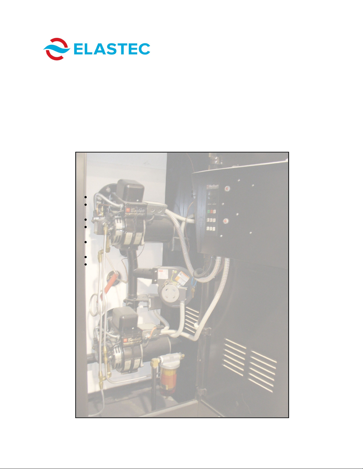
Fuel: There are two options for the supply of diesel to the unit:
Gravity-fed system: A large fuel tank supplies the unit. The bottom of the
tank should be higher than the top of the burner on the secondary chamber.
Mounted tank: Fuel supply is mounted under the unit with a fuel pump and
return line.
CONTROL PANEL OPERATION
The burn times are adjusted using the UP and DOWN arrows on the controller
located on the control panel (see Page 7). When the cycle time is chosen, push
the START button and the MediBurn30 will begin its operating cycle. To change
the cycle time, push the STOP button and change the cycle time. Then restart
the unit.
COMPLETE CYCLE
Unit is switched on, burn chamber door will lock and the 30-second purge
begins (fans only).
7-minute pre-heat (secondary chamber burner fires and begins the pre-heat
process).
Burn cycle begins.
After the firing cycle is complete, blowers in both primary and secondary
chambers blow cool air until the temperature of the unit is 300 degrees
Celsius. If the temperature rises again, blowers will be activated cyclically
until the temperature remains below 300 degrees Celsius.
OPERATING TEMPERATURES
Temperature readouts are visible on the control panel. The unit is designed to
preheat the secondary chamber for 7 minutes before incineration begins in the
primary chamber. Exhaust temperatures are automatically controlled to range
from 1000 degrees Celsius to 1025 degrees Celsius during the burn cycle.
Lower temperatures noted during operation indicate that the materials in the
batch load have been incinerated.
MEDIBURN30 6 D-115 Rev 010
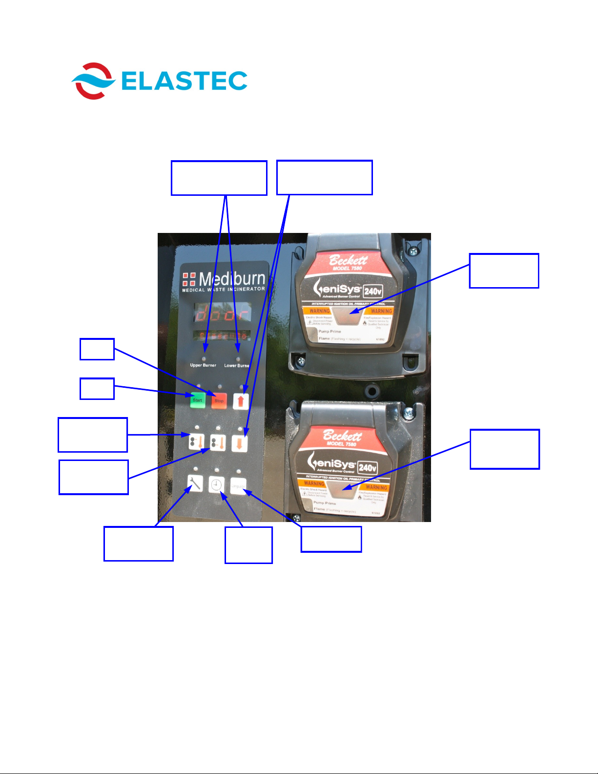
CONTROL PANEL
www.elastec.com
Stop
Start
Upper
Temperature
Indicator light is red
when burner is on.
Burn time
adjustment
Upper Burner
Reset Button
Lower Burner
Reset Button
Lower
Temperature
Maintenance
Information
MEDIBURN30 7 D-115 Rev 010
Burn
Time
Language
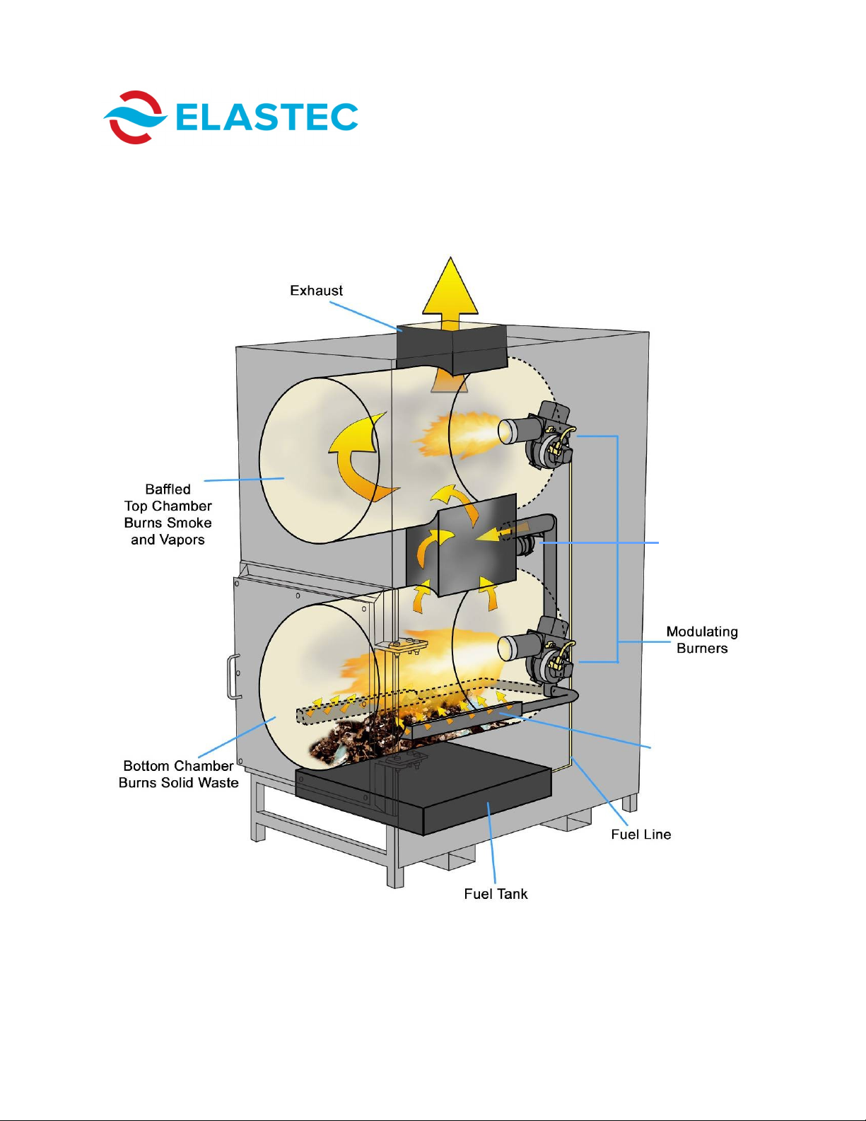
HOW IT WORKS
www.elastec.com
Under-Air
Blower
Under-Air
Piping
MEDIBURN30 8 D-115 Rev 010
HOW IT WORKS
www.elastec.com
The operating functions of the burners on the MediBurn30 differ from those of
the original MediBurn in that the 30 has two-stage pumps which oscillate based
on temperature, rising and falling during normal burn operation. As the unit
starts its burn cycle and the temperature climbs, the pumps decrease fuel
usage at specified temperatures. This lowers the heat output of the burners.
However, the temperature continues to rise as the under-fired air in the
primary chamber raises the load temperature by increasing the flame of the
burning material. This process increases temperature to a preset point where
the lower burner can shut off, further reducing fuel usage. The upper burner
also oscillates fuel usage as it works to keep the stack temperature at or above
1000 degrees Celsius.
The MediBurn30 incorporates two 24-volt continuous stall motors. One of
these motors is used to operate and maintain the automatic door lock, which is
activated when the START button is pushed. The other 24-volt motor is used to
open and close the under-fired air bypass.
All of these components are controlled by temperature through the system
controller. Should you as the owner or system user have problems with these
components, please refer to the Troubleshooting Guide found on Pages 19-22
or call Elastec at (618) 382-2525.
MEDIBURN30 9 D-115 Rev 010
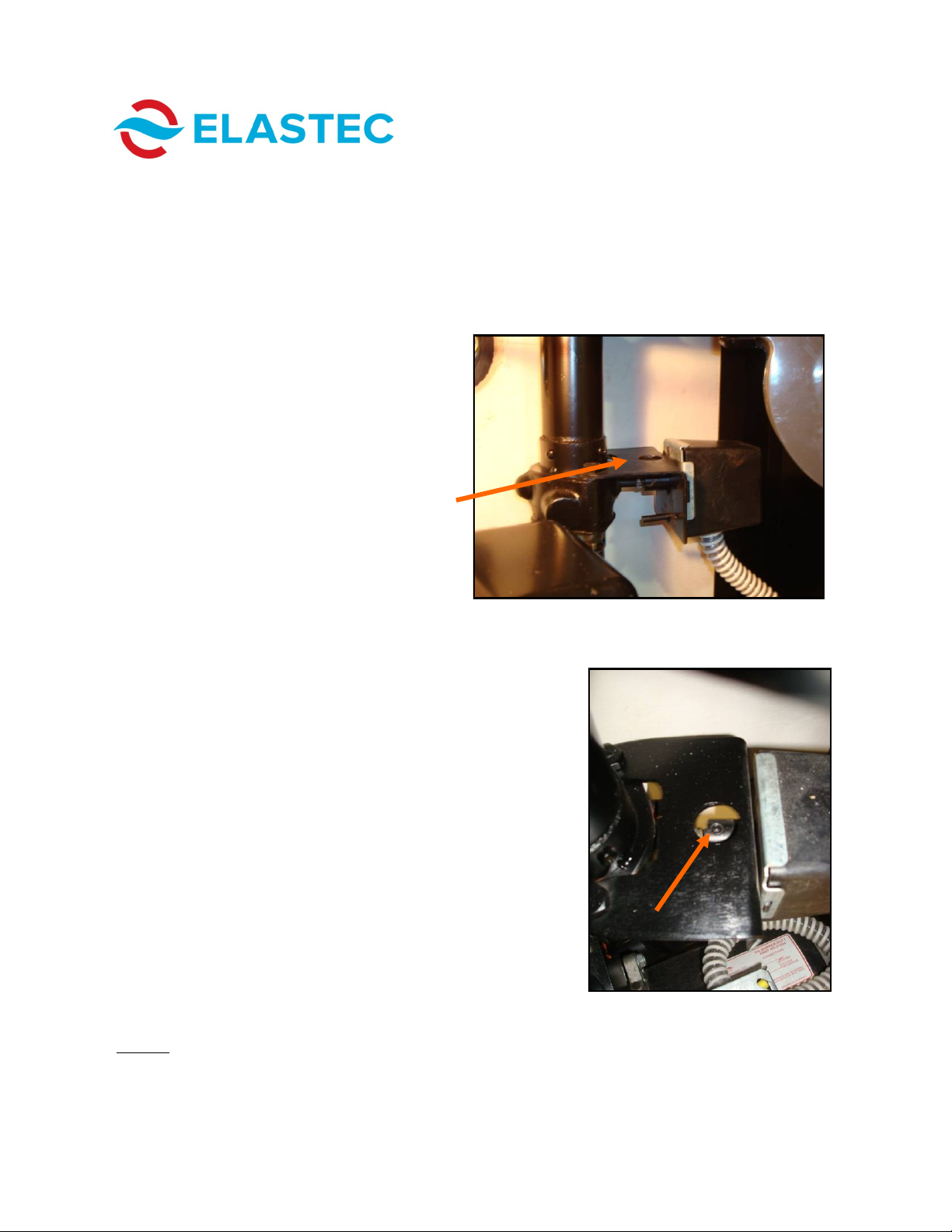
BUTTERFLY ASSEMBLY
www.elastec.com
The butterfly assembly, located just above the lower burner, is used to open
and close an air bypass. This motor function should be checked on a regular
basis to ensure that it is working properly. In the top of the motor bracket,
there is a small hole that will allow you to view the shaft coupler set screw.
This set screw will turn and disappear out of sight when the motor is activated.
This process can be easily viewed when the lower chamber temperature is
between 600° Celsius and 1000°
Celsius (1112° Fahrenheit and 1832°
Fahrenheit).
The picture to the right shows the set screw
(arrow) as it appears when the MediBurn30 is in
idle. This set screw will rotate out of view when the
temperature climbs above 600° Celsius (1112°
Fahrenheit), indicating the butterfly valve has
opened, allowing air to bypass into the under-air
system. When the lower chamber temperature
reaches 1000° Celsius (1832° Fahrenheit), the
butterfly valve will close and the set screw will
again be visible. It can also be felt by using your
finger. This bracket rarely gets very hot, due to the
cold air that passes through the tubing and
butterfly valve, making it possible to check this by
hand as well as sight. Should you have to replace
this motor, be sure to orient the set screw so that it
can be viewed through the view hole.
NOTE: It is important to maintain this motor in good working condition, as it is
instrumental in the process of fuel savings.
MEDIBURN30 10 D-115 Rev 010
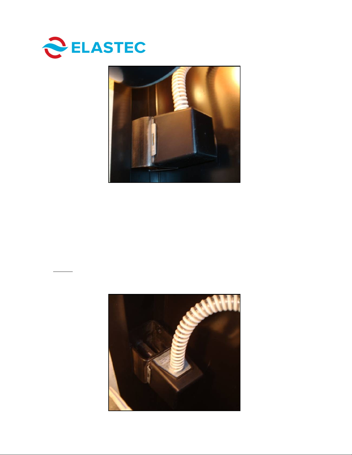
DOOR LOCK MOTOR ASSEMBLY
www.elastec.com
The door lock motor assembly is located on the right side of the burner
compartment. It is designed to lock the burn chamber door as soon as the
START button is pushed. The door-locking system is designed as a safety
feature and is built in such a way that, if tampered with, the MediBurn30 will not
start. When the burn chamber door is open, the controller scrolls “door open,”
and if the burn chamber door is opened during the burn cycle, the unit will
automatically cycle into cool mode and the unit will have to cool to 300C before
restart can begin.
NOTE: The MediBurn30 must always be cooler than 300° Celsius (572°
Fahrenheit) before trying to load unit.
MEDIBURN30 11 D-115 Rev 010
 Loading...