

ELANT EL6275CU Datasheet
EL6275C - Product Brief
4-Channel Laser Diode Driver + Oscillator
EL6275C - Product Brief
Features
• Shrink-Small Outline Package
• Voltage-controlled output current
source requiring one external set
resistor per channel
• Current-controlled output current
source
• Rise time = 3.0ns
• Fall time = 3.5ns
• On-chip oscillator with frequency
and amplitude control by use of
external resistors to ground
• Oscillator to 500MHz
• Oscillator to 100mA pk/pk
• Single +5V supply (±10%)
• Current amplification = 100
• Disable feature for power-up
protection and power savings
• TTL/CMOS control signals
Applications
• CD-RW applications
• Writable optical drives
• Laser diode current switching
Ordering Information
Part No Package Tape & Reel Outline #
EL6275CU QSOP-16 MDP0040
General Description
The EL6275C is a four channel laser diode current amplifier that provides controlled current to a grounded laser diode. Channels 2, 3, and
4 should be used as the write channels, with switching speeds of
approximately three nanosecond rise/fall time. All four channels are
summed together at the I
output, allowing the user to create multi-
OUT
level waveforms in order to optimize laser diode performance. The
level of the output current is set by an analog voltage applied to an
external resistor which converts the voltage into a current at the IIN pin
(virtually ground). The current seen at this pin is then amplified to
become a current source at pin I
OUT
.
An on-chip 500MHz oscillator is provided to allow output current
modulation when in any mode. This is turned on when the OSCEN pin
is held high. Complete control of amplitude and frequency is set by
two external resistors connected to ground at pins RFREQ and RAMP
(see graphs in this data sheet for further explanation).
Output current pulses are enabled when an ‘L’ signal is applied to the
OUTEN pin. No output current flows when OUTEN is ‘H’ and additional laser diode protection is provided since the OUTEN input will
float high when open. Complete I
shutoff is also achieved by hold-
OUT
ing the ENABLE pin low, which will override all other control pins.
The external resistors allow the user to accurately and independently
set each amplifier transconductance by applying a voltage to each
resistor, without restriction on the voltage range, thus ensuring broad
voltage DAC compatibility. Alternatively, the IIN pin can be biased
from a current DAC or other current source.
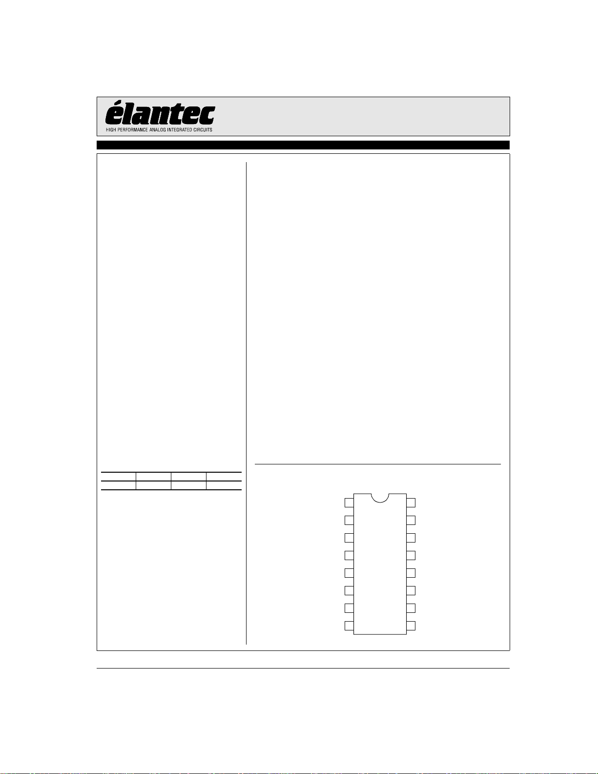
Connection Diagram
1
IINR
2
IIN2
3
RFREQ
4
IIN3
5
IIN4
6
OUTEN2
7
OUTEN3
8 9
OUTEN4
Note: All information contained in this data sheet has been carefully checked and is believed to be accurate as of the date of publication; however, this data sheet cannot be a “controlled document”. Current revisions, if any, to these
specifications are maintained at the factory and are available upon your request. We recommend checking the revision level before finalization of your design documentation.
© 2001 Elantec Semiconductor, Inc.
VCC
VCC
IOUT
GND
RAMP
ENABLE
OSCEN
VCC
16
15
14
13
12
11
10
January 29, 2001
EL6275C - Product Brief
4-Channel Laser Diode Driver + Oscillator
EL6275C - Product Brief
General Disclaimer
Specifications contained in this data sheet are in effect as of the publication date shown. Elantec, Inc. reserves the right to make changes in the circuitry or specifications contained herein at any time without notice. Elantec, Inc. assumes no responsibility for the use of any circuits described
herein and makes no representations that they are free from patent infringement.
WARNING - Life Support Policy
Elantec, Inc. products are not authorized for and should not be used
within Life Support Systems without the specific written consent of
Elantec, Inc. Life Support systems are equipment intended to sup-
Elantec Semiconductor, Inc.
675 Trade Zone Blvd.
Milpitas, CA 95035
Telephone: (408) 945-1323
(888) ELANTEC
Fax: (408) 945-9305
European Office: +44-118-977-6020
Japan Technical Center: +81-45-682-5820
port or sustain life and whose failure to perform when properly used
in accordance with instructions provided can be reasonably
expected to result in significant personal injury or death. Users contemplating application of Elantec, Inc. Products in Life Support
Systems are requested to contact Elantec, Inc. factory headquarters
to establish suitable terms & conditions for these applications. Elantec, Inc.’s warranty is limited to replacement of defective
components and does not cover injury to persons or property or
other consequential damages.
January 29, 2001
2
Printed in U.S.A.
 Loading...