

Elan Home Systems D-1650 Owners manual
16 CHANNEL DIGITAL POWER AMPLIFIER
INSTALLATION MANUAL AND USER©S GUIDE
D1650/D1651
SIXTEEN CHANNELS
OF DIGITAL COOL

1. INTRODUCTION
Thank You!
Thank you for purchasing this product. The ELAN
D1650 Digital Power Amplifier has been designed
specifically for custom installers to provide the ultimate solution for multi-room, whole-house applications. Sixteen channels of clean, powerful audio
can be combined in dozens of different ways to suit
virtually any situation that may be encountered in
whole-house distributed audio systems. The D1650
uses an Audio Bus system that allows inputs and
outputs to be combined in many ways without the
use of extraneous patch cables. ‘Class T’ Digital
technology and ACE™ (Automatic Clip Eliminator™)
allow efficient use of power, ensuring clean, accurate audio at all volume levels in any application.
Remote triggers and turn-on circuits for each channel enable the installer to integrate this amplifier
easily into any ELAN multi-zone system or in stand-
alone applications.
The ELAN Story
Located in Lexington, KY, USA, ELAN Home
Systems has designed innovative multi-room
audio/video systems since 1989. ELAN systems
were the first to integrate music, intercom and TV
distribution features that used the homeowner’s
stereos, televisions and telephones to create the
whole-house entertainment experience. These systems allow people to move room to room, controlling centrally located equipment with ease
ELAN’s product line includes:
Power Amplifiers
Zoned Pre-Amps
Intelligent Keypads
LCD Color Touch Panels
In-Wall and In-Ceiling Speakers
Outdoor Speakers
System Controllers
Volume Controls
Telephone-Based Intercom Controllers
Video Switchers,
Digital Music Management Systems
Accessories for Home Systems Installation
ELAN has introduced nearly 300 new products in
the last seven years and has been honored with 42
industry awards in past 5 years!
Safety Concerns
This amplifier is HEAVY! Use caution when lifting
the unit. Please ensure that whatever supports this
amp is able to hold at least 50 POUNDS safely.
Use only grounded outlets when powering this
product. Making any modification to the power cord
could cause unsafe operation and will void the manufacturer's warranty.
The D1650 is very powerful and should have its own
dedicated 15 Amp AC circuit. If a dedicated circuit
is not available, one should be installed by a
licensed electrician.
D1650/D1651 INSTALLATION MANUAL
Page 2 © ELAN Home Systems, Inc. 2004 • All rights reserved. 7/04
ELAN HOME SYSTEMS
ALL CONNECTIONS SHOULD BE MADE
WITH THE AMPLIFIER TURNED OFF
AND UNPLUGGED FROM POWER.
DAMAGE CAN OCCUR TO EQUIPMENT
IF IMPROPER CONNECTIONS ARE MADE!
THIS AMPLIFIER IS NOT BRIDGEABLE!
DO NOT TRY TO BRIDGE
OR COMBINE OUTPUTS!
DAMAGE TO THE AMP WILL OCCUR.
© ELAN Home Systems, Inc. 2004 • All rights reserved. 7/04 Page 3
D1650/D1651 INSTALLATION MANUAL
ELAN HOME SYSTEMS
IMPORTANT SAFETY INFORMATION
Read Information—All the safety and operating information should be read before the appliance is operated.
Follow Information—All operating and use information should be followed.
Retain Information—The safety and operating information should be retained for future reference.
Heed Warnings—All warnings on the appliance and in the operating instructions should be heeded.
Wall Mounting—Mounting of this appliance should be done only by an authorized installer.
Ventilation—The appliances should be situated so that their location or position does not interfere with their proper ventilation.
These appliances should never be placed near or over a radiator or heat register. These appliances should not be placed in a built-in
installation such as a bookcase or cabinet that may impede the flow of air through the ventilation openings.
Non-Use Periods—Appliances that are left unattended and unused for long periods of time should be de-energized.
Power Sources—The appliances should be connected to a power supply only of the type described in the operating instruc-
tions or as marked on each appliance. If you are not sure of the type of power supply to your home, consult your authorized ELAN dealer or local power company.
Grounding or Polarization—These audio products must be connected to a grounding-type alternating-current circuit on
a dedicated circuit breaker. This is a safety feature. The green safety wire from the A.C. circuit must be connected.
Water and Moisture—To reduce the risk of electric shock or fire, these appliances should not be used near water––for exam-
ple, near a bathtub, washbowl, kitchen sink, laundry tub, in a wet basement, or near a swimming pool.
Power Cord Protection—A.C.Power supply circuits should be routed by a certified electrician only, in accordance with the
NEC standards.
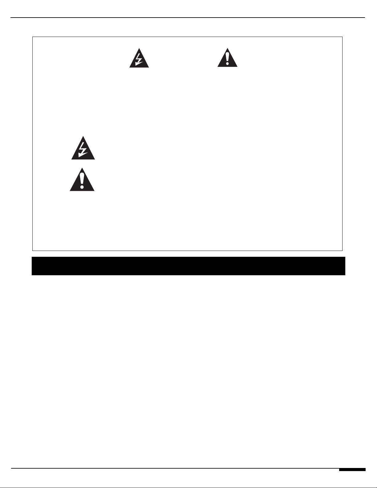
CAUTION: TO REDUCE THE RISK OF ELECTRIC SHOCK, DO NOT
REMOVE COVER (OR BACK). NO USER SERVICEABLE PARTS INSIDE.
REFER SERVICING TO QUALIFIED SERVICE PERSONNEL.
The lightning flash with arrowhead symbol within an equilateral triangle
is intended to alert the user to the presence of uninsulated "dangerous
voltage" within the product's enclosure that may be of sufficient
magnitude to constitute a risk of electric shock to persons.
The exclamation point within an equilateral triangle is intended to alert
the user to the presence of important operating and maintenance
(servicing) instruction in the literature accompanying the appliance.
WARNING
RISK OF ELECTRIC SHOCK
DO NOT OPEN!
WARNING: TO REDUCE THE RISK OF FIRE OR SHOCK,
DO NOT EXPOSE THIS APPLIANCE TO RAIN OR MOISTURE.

D1650/D1651 INSTALLATION MANUAL
Page 4 © ELAN Home Systems, Inc. 2004 • All rights reserved. 7/04
ELAN HOME SYSTEMS
Water and Moisture—To reduce the risk of electric shock or fire, these appliances should not be used near water––for exam-
ple, near a bathtub, washbowl, kitchen sink, laundry tub, in a wet basement, or near a swimming pool.
Power Cord Protection—A.C.Power supply circuits should be routed by a certified electrician only, in accordance with the
NEC standards.
Telephones—Avoid using a telephone (other than a cordless type) during an electrical storm. There may be a remote risk of elec-
trical shock from lightning. Do not use a telephone to report a gas leak if the leak is in the vicinity of the ELAN electronic equipment
because of risk of fire or explosion.
Cleaning—Turn off the circuit breaker to this audio product before cleaning. Do not use liquid or aerosol cleaners. Use a damp cloth
for cleaning.
Power Lines—An outdoor antenna should be located away from power lines. When installing an outside antenna system, extreme
care should be taken to avoid touching power lines or circuits, as contact with them may be fatal.
Outdoor Antenna Grounding—If an outside antenna or cable system is connected to these audio products, be sure the
antenna or cable system is grounded so as to provide some protection against voltage surges and built-up static charges. Section 810
of the U.S. National Electrical Code, and Section 54 of the Canadian Electrical Code, provide information with respect to proper grounding of the mast and supporting structure, grounding of the lead-in wire to an antenna discharge unit, size of grounding conductors, location of antenna-discharge unit, connection to grounding electrodes, and requirements for the grounding electrode. See the grounding
diagram (right).
Overloading—Do not overload wall outlets and extension cords, as this could result in fire or electric shock.
Object and Liquid Entry—Never insert objects of any kind through
the openings of these appliances, as they may touch dangerous voltage points
or short-out parts that could result in a fire or electric shock. Care should be
taken so that objects do not fall and liquids are not spilled into the appliance
through openings in the enclosure.
Servicing—Do not attempt to service these appliances yourself, as open-
ing or removing covers may expose you to dangerous voltage or other hazards.
Refer all servicing to qualified service personnel.
Damage Requiring Service—These appliances should be serv-
iced by qualified service personnel when:
• A power supply connection or a plug has been damaged or
• If liquid has been spilled into the appliance or objects have fallen into the
appliance or
• The appliance has been exposed to water or moisture or
• The appliance does not appear to operate normally or exhibits a marked change in performance or
• The appliance has been dropped or the enclosure damaged.
Replacement Parts—When replacement parts are required, be sure the service technician has used replacement parts spec-
ified by the manufacturer or that have the same characteristics as the original part. Unauthorized substitutions may result in fire, electric shock, or other hazards. The Master Control Unit battery should be replaced only after turning the power off and only by an authorized installer.
Safety Check—Upon completion of any service or repairs to this audio product, ask the service technician to perform safety
checks to determine that the audio product is in proper operating condition.
Lightning—For added protection for these audio products during an electrical storm, or when they are left unattended and unused
for long periods of time, turn off the circuit breaker, and disconnect the antenna or cable system. This will prevent damage to the audio
products due to lightning and power-line surges.
WARNING
RISK OF ELECTRIC SHOCK
DO NOT OPEN
Grounding
Diagram
ELECTRIC
SERVICE
EQUIPMENT
NEC - NATIONAL ELECTRICAL CODE
CEC - CANADIAN ELECTRICAL CODE
GROUND
CLAMPS
ANTENNA
LEAD-IN WIRE
ANTENNA LEAD-IN WIRE
(CEC SECTION 54-200)
(NEC SECTION 810-20)
GROUNDING CONDUCTORS
(CEC SECTION 54-200)
(NEC SECTION 810-21)
GROUND CLAMPS
POWER SERVICE GROUNDING
ELECTRODE SYSTEM
(CEC SECTION 10-700)
(NEC ARTICLE 250, PARTH)

© ELAN Home Systems, Inc. 2004 • All rights reserved. 7/04 Page 5
D1650/D1651 INSTALLATION MANUAL
ELAN HOME SYSTEMS
Table of Contents
1. Introduction
Thank You/ELAN Story........................................................... 2
Safety Information.................................................................. 3
System Overview....................................................................6
Specifications......................................................................... 6
Features.................................................................................. 7
Class ‘T’ Explained ............................................................... 8
2. Connections and Applications
Independent Stereo Zones.................................................... 9
Two Room Stereo Zones......................................................... 10
Stereo Zones with Mono Sub-Zones.................................... 11
Mono Zones........................................................................... 12
Bus Mode............................................................................... 13
Triggers................................................................................... 14
3. Setup
Setting Channel Levels.......................................................... 15
Lockout................................................................................... 15
Factory Default....................................................................... 16
Changing LED Brightness..................................................... 16
4. Troubleshooting.................................................................... 17
Warranty.........................................................................................Back Page
Specifications
Audio Section
Power Rating - RMS
Output Power (16 CH Stereo) . . . . . . . 60Wrms @ 4 ohms/CH
Output Power (16 CH Stereo) . . . . . . . 45Wrms @ 8 ohms/CH
Frequency Response . . . . 20 Hz to 20 kHz, -.3dB into 8 ohms
Full Power Bandwidth . . . . . . . . . . . . . . . . . . . 10Hz to 50 kHz
Signal-To-Noise . . . . . . . . . . . . . . . . . . . . > 102db (A-weighted)
Channel Separation . . . . >-70dB (channel to channel @ 1 kHz)
Total Harmonic Distortion . . . . . . . . . . . . . . . . . . . . . . < .04%
Dynamic Headroom . . . . . . . . 120W @ 4ohms, 90W @ 8 ohms
Intermodulation Distortion . . . . . . . . . . . . . . . . . . . . . < 0.1%
Voltage Gain (AV) . . . . . . . . . Continuously Variable from 0 - 24
Slew Rate . . . . . . . . . . . . . . . . . . . . . . . . . . > 20V/microsecond
Input Impedance . . . . . . . . . . . . . . . . . . . . . . . . . . . 49 K ohms
Input Sensitivity . . . . . . . . . . . . . . . . 790Vrms (45W @ 8 ohms)
Connectors
Input/Loop Outputs . . . . . . . . . . . . . . . . . . . . Gold RCA Phono
Speaker Output . . . . . . . . . . . . . . . . . . . . . . WECO Terminators
Power
AC Power Requirements . . . . . . . . . . . . .120 VAC, 1200 Watts
Power Supply . . . . . . Ultra-high efficiency toroidal transformer
Triggers
Remote Trigger Inputs . . . . . . . . . . . . . . . 5 to 24 Volts AC/DC
Trigger Loop Output . . . . . . . . . . . . . . . . . . . . .+12VDC @0.1A
Dimensions/Weight
Dimensions . 5.25 x 17.0 x 15 (inches)/13.34 x 43.18 x 38.1 (cm)
Rack Face . . . . . . . . . . . . . 19 X 5.25 (inches)/48.26 x 13.34(cm)
Weight . . . . . . . . . . . . . . . . . . . . . . . . . . . . . . . . 50 lbs/22.68 kg
D1650/D1651 INSTALLATION MANUAL
Page 6 © ELAN Home Systems, Inc. 2004 • All rights reserved. 7/04
ELAN HOME SYSTEMS
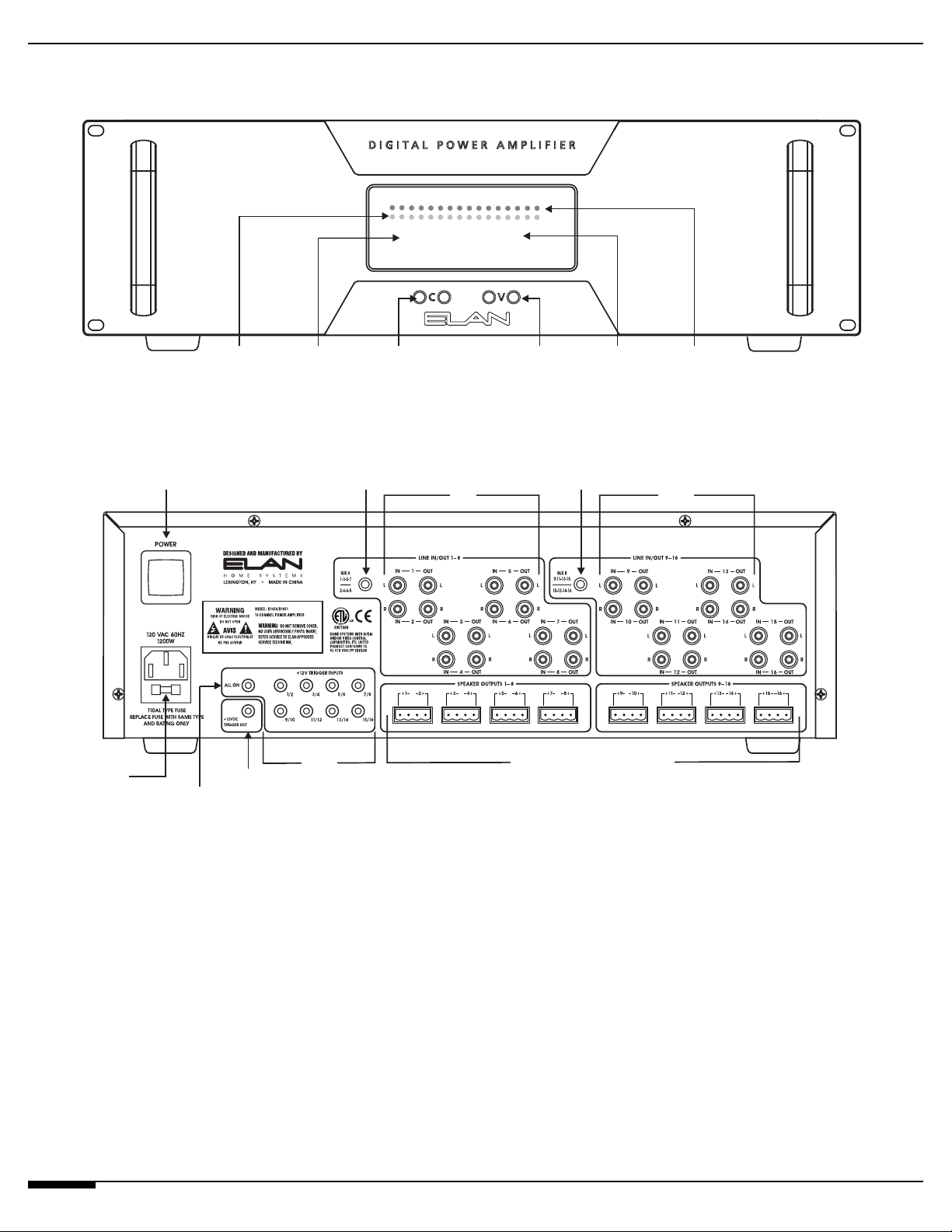
System Overview
CH I6 VOL 75
FRONT
BACK
FUSE
POWER
SWITCH
+12V ‘ALL ON’
TRIGGER
SIGNAL
PRESENCE
LEDS
+12VDC
TRIGGER
OUT
CHANNEL
SELECT
DISPLAY
+12V
TRIGGER
INPUT
PAIRS
1-16
CHANNEL
SELECT
DOWN/UP
BUTTONS
BUS A
BUTTON
LINE INPUTS/
LOOP OUPUTS
1-8
VOLUME
DOWN/UP
BUTTONS
SPEAKER OUTPUTS 1-16
VOLUME
DISPLAY
BUS B
BUTTON
LEVEL
LINE INPUTS/
LOOP OUPUTS
CHANNEL
CLIPPING
LEDS
9-16
 Loading...