

ELAN AUDIO FALCON-10 Operating Instructions Manual

1
Operating Instructions and Suggestions
FALCON-10 On-Air Mixer
It is virtually impossible to write an operating manual for an On-Air Mixer that will satisfy everyone
Every Operator, Presenter or Rad io Ann ouncer wil l with experience develop a u ni que oper at i ng t ec hni que
to suit a particular presentation style, and may not agree with everything stated in this
Despite the above, here are th e Operating Instruct ions and Suggest ions for the Falcon- 10 On-Air Mixer,
to be considered as a basic guide for beginners only
The Falcon-10 is the “Entry Level” Mixer in the Elan Aud io range, and is provided with 8 Stere o High
Level, and 2 Mono Microphone Level Input Channels
Each Input Channel is provided with 3 Switches, OFF, ON, CUE and a Linear Slide Fader
The Switches are il luminated by LED’s, and give “ Clickless” control of Channel O FF, Channel ON and
Channel to CUE with the Fader controlling the audio level to the Program Output or the Cue System
The Switches are Interlocked electronically with only one active at a time allowing switching in any
sequence, such as switching from CUE direct to ON without having to go through the OFF position
Input Channels 1 to 7 are identical Stereo High Level Inputs
Input Channel 8 can be used as either a Stereo High Level Input, or as a Mono Telephone Input
An external Telephon e H ybrid Unit, not su pplied with the Fa lcon-10 M ixer, m ust be ins talled betwee n the
Telephone Line and High Level Input 8 in order to record or broadcast telephone conversations
A basic description of Telephone Systems Connection and Operation follows later in this
Input 9 is the Guest Microphone Input, and input 10, the Announcer Microphone Input
An Interlocking 5 Pos ition Stereo Switch
(A)
see page 8, not wired as supplied, is located to the Left in
the riser panel and intended for a possible input line expansion to High Level Input 1
The FLCN-RC Remote Start-Stop Module, supplied to order as an option for the Falcon-10, provides
remote Start and Stop f unctions via the Ch annel On and O ff Switches to Prof essional Sour ce Equi pment
and makes operation of the mixer easier
We assume here that Gain Settings of all input channels has been adjusted correctly by the station
technician to match the levels of sourc e equipm ent suc h as CD Pla yers, M icroph ones etc connec ted t o it,
and also assume the mixer has been fully inst alled with a suitable Mo nitor Amplifier, Monitor Speakers,
Headphones, Off-Air Monitor Receiver etc and ready for operation
First a brief discussion on Audio Levels and Audio Metering
All On-Air Audio Mixers produc ed by Elan Audi o are designe d to be forgiv ing and eas y to use and ar e in
themselves quite tolerant of incorrect Audio Levels
Nonetheless, it is very important, in order to obtain best possible Transm itted Sound Quality from the
station that any audio equipment including the On-Air Mixer be operated at its correct audio levels
Operating with Correct Audio Levels are particularly important to the station Audio Processor that will
attempt to keep modulation levels correct
2
It may in the proces s “Suck Up Noise” on low audio levels , and can on excessively hig h audio levels
produce Distortion, unpleasant Over Compressed Squashed Sound and “Pumping Effects”
Reading Audio Level Met e rs , and op er ati ng equ ipment at its correct le vels is not diffic ult , bu t d oes r equ ire
some Basic Skill and Attention, as well as an apprec iation of Audio Quality
Unfortunately, a bewil dering number of different types and st yles of Audio Le vel Indicators are found on
Domestic, Semi Professional and “On-Screen” Meters on Computer based Audio Equipment
Some make some s ort of s ense and are quit e go od if you un derstan d ho w to r ead them , whi le ot hers are
completely useless, including mechanical meters provided with VU Scales that are Virtually Useless
For Broadcasting in Australia, there are only two recognised Audio Metering Standards
One is the IEC Type II Peak Programme Meters, identical ballistics, available with two different scales
IEC Type II A, BBC Type, scaled 1 to 7, and the IEC Type II B scaled –12 to +12
The other, and most common type is the VU Meter
A “Real VU Meter” conf orming to th e ANSI St andard, whether a m echanic al t ype or a colum n of LED ’s is
a meaningful Volume Indica tor, and very pleasant to us e whi le as mentioned above, sp ur io us Audio Level
Meters with VU Scaling are Virtually Useless
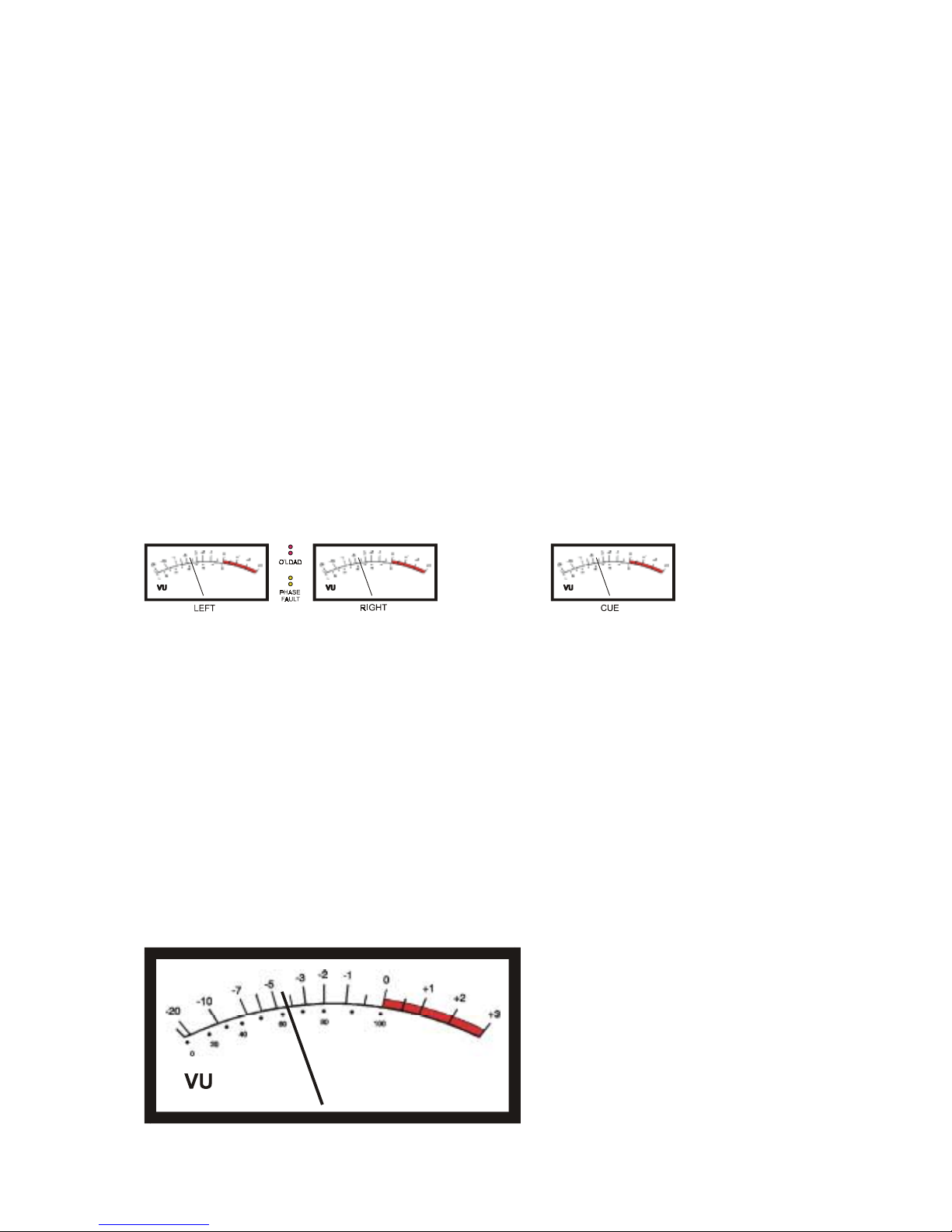
The Falcon-10 is pro vided with three mechanical V U Meters, an LED Overload indicator , and a Phase
Fault Indicator
(B)
Two of the VU Meters are arranged to indicate Left and Right Channe l Aud io Le ve ls , th e third VU Meter is
connected to the Cue Channel allowing the operator to set the Channel Fader to correct level before
switching the channel To-Air
The LED Overload Indicator is s hared between Left and R ight Channels and opera tes by sensing Peak
Levels, and set to Flash at a level 10 dB above 0 VU to in dicat e whenever the Perm itted M aximum Level
of the system is exceeded, and possible overload occurring making the station sound bad
The Phase Fault Indicator is basically a Mono Compatibility check facility and is complicated to explain
It will flash whene ver the Sum of L+R is less than L-R and it is perfectly norm al for this to flash bri efly
when playing normal Stereo Music material
If illuminated m os t of the time, a Phase Revers al Pr ob lem on the recorded material being played To-Air is
indicated and can be verified by pressing the Mo no Chec k Button, described further under Monit orin g
The combination of VU Meters and the Overlo ad LED Indicator mak es it easy to operate the Falc on-10
Mixer at the correct Audio Levels

3
As a general guide for Microphones, adjust Channel Gain when speaking into the Microphone at a
Normal Voice Level, to indicat e between – 3 VU and – 4 VU, and allow the Overload I ndicator to flash
briefly 2 to 3 times a minute
For Recorded Music, “Best Level” varies somewhat, depending on the type of music being broadcast
Modern “Pop” Music is generally recorded to have a very limited “Dynamic Range”
Adjust Channel Gain to peak between 0 VU an d + 1 VU, and allow the Ov erload Indica tor to flash br iefly
2 to 3 times a minute
Country, Jazz and Blues is recorded with a reasonably wide “Dynamic Range”
Adjust Channel Gain to indicate arou nd –3 dB on normal passages, and peak to 0 VU, and allow the
Overload Indicator to flash briefly 2 to 3 times a minute
Classical Music is recorded with a very wide “Dynamic Range”
It is very diffic ult to give definite directions in regard to A udio Levels for Class ical Music as correct level
can range from – 15 or - 20 VU on quiet passages to 0 VU or maybe even + 2 VU on loud passages
As an example, the Harp produces ver y sharp peaks that can flash the Overlo ad Indicator with the VU
Meter reading maybe – 15 VU
As a general rule, allow the Overload Indicator to flash briefly 1 or 2 times a minute on loud passages
Operating ON-OFF-CUE switches and Faders
Each Input Channel on the Fa lcon-1 0 Mixer is provide d with a Slide Fa der for Au dio Lev el control
(C1)
,
and three Illuminated Push Button Switches
(C2)
controlling Channel OFF, Channel to CUE, and
Channel ON to the Mixer Output via the Mixing Buses
If the optional FLCN-RC Module is fitted, remote Start and Stop of Professional CD Players, other
Professional Sourc e equipment and Control of a Telephone Hybrid Unit etc is pro vided by the Channe l
ON and OFF Buttons making operation of the Falcon-10 extremely easy
If the FLCN-RC Module is not fitted, Start and Stop control of the Source Equipment, must be done
manually by the operator
The functions of the Channel Control Buttons are as follows
OFF, the Channel is switched OFF with the LED in button illuminated, indicating Channel OFF
CUE, the Channel is switched to CUE with the LED in button illuminated, indicating Channel to CUE
For a Stereo High Level Input Channel, audio is fed to the CUE VU Meter, the CUE Speaker, and to
one side of the Operators or Announcers Headphone
For a Microphone Channel, audio is fed to the CUE VU Meter and to one side of the Operators or
Announcers Headphone, With a Microphone Channel to CUE, the CUE and Monitor Speakers are Muted
Level can be Pre-Set by moving the Fader to give correct level indication on the VU Meter, and also
allows the operator to listen to audio before switching this To-Air
ON, the Channel is switched on to the Mixer Output via the Mixing Buses
With a Microphone Channel switched ON, the CUE and Monitor Speak ers are Muted, and a Relay
Contact closed to operate the Studio On-Air Light
High Level Input 8 if not us ed as the T elephon e Channe l Inp ut operat es ident ical ly to al l ot her High Le vel
Inputs
 Loading...